SpECiFiCATionS
SpECiFiCATionS
SpECiFiCATionS

Create successful ePaper yourself
Turn your PDF publications into a flip-book with our unique Google optimized e-Paper software.
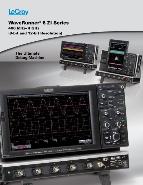
WaveRunner ® 6 Zi Series<br />
400 MHz– 4 GHz<br />
(8-bit and 12-bit Resolution)<br />
The Ultimate<br />
Debug Machine
ThE UlTiMATE DEbUg MAChinE<br />
Superior Validation,<br />
Debug, Analysis<br />
The WaveRunner ® 6 Zi defines<br />
superiority in a test instrument with<br />
a powerful feature set including a<br />
wide range of application packages,<br />
advanced triggering to isolate events,<br />
a user interface developed for quick<br />
and easy navigation, a wide range<br />
of probing options, and lightning-fast<br />
performance.<br />
2<br />
Most Comprehensive<br />
Serial Data Analysis<br />
WaveRunner 6 Zi offers the most<br />
tools for serial data analysis. With<br />
over 17 trigger, decode, and compliance<br />
solutions, WaveRunner 6 Zi<br />
can address problems with unique,<br />
powerful views and automated<br />
tools. The unique measurement<br />
toolset, ProtoSync, combines the<br />
oscilloscope view with a simultaneous<br />
view of data link layer decodes on<br />
the same instrument.<br />
Excellent Signal Fidelity<br />
The WaveRunner 6 Zi oscilloscope<br />
family features a pristine signal path<br />
that offers unmatched signal fidelity<br />
with low noise. The WaveRunner HRO<br />
offers a 12-bit ADC, resulting in up to<br />
55 dB Signal-to-Noise Ratio (SNR).<br />
This performance is augmented by<br />
a huge offset and timebase delay<br />
adjustment to allow easy signal and<br />
amplifier performance assessment<br />
and zooming on vertical and horizontal<br />
signal characteristics.
Unbelievable Performance<br />
The WaveRunner 6 Zi oscilloscope is the most versatile<br />
scope in the 400 MHz to 4 GHz class. The performance<br />
offered is unmatched, offering deep memory, 40 GS/s<br />
sample rate, low noise and fast operation to help get<br />
the job done quickly and accurately.<br />
The WaveRunner HRO 6Zi defines the best in class noise<br />
performance with a 12 bit ADC to provide the best<br />
resolution. The HRO 6Zi also features deep memory<br />
options up to 256 Mpts/Ch.<br />
The toolset provides every necessity for an engineer<br />
to validate a design, debug errors at board bring up,<br />
and offer powerful analysis to characterize<br />
an embedded system. The WaveRunner 6 Zi<br />
is the ultimate debug machine.<br />
A new Way to<br />
navigate and View<br />
The WavePilot control<br />
area provides convenient<br />
control of Cursors, Decode,<br />
WaveScan, History,<br />
LabNotebook, and Spectrum<br />
by their respective function<br />
buttons on the front panel.<br />
The SuperKnob is a joystick-like<br />
knob in the center of the WavePilot<br />
control area used to easily navigate through<br />
tables, zoom and position waveforms, and<br />
quickly document and annotate your setups.<br />
Simply slide the button on the left side of the<br />
display and rotate upwards 90º. The display will<br />
automatically change from landscape to portrait<br />
mode. The display will also pivot upwards and<br />
downwards to optimize viewing angle.<br />
3
4<br />
CoMplETE DEbUg SolUTion FRoM 400 Mhz–4 ghz<br />
WaveRunner 6 Zi combines the<br />
power of a fully featured multi-purpose<br />
oscilloscope, a dedicated logic analyzer<br />
for mixed signal design, and a protocol<br />
analyzer for serial data debug.<br />
1. Industry leading performance—<br />
400 MHz—4 GHz, 40 GS/s,<br />
256 Mpts of analysis memory<br />
2. 12.1" Widescreen (16 x 9) high<br />
resolution WXGA color touch<br />
screen display<br />
3. 90º rotating and tilting display for<br />
optimal viewing of signals<br />
4. Small footprint, only 8.1" deep<br />
5. Easy connectivity with two<br />
convenient USB ports on the<br />
front, two on the side<br />
6. USBTMC (Test and Measurement<br />
Class) port simplifies programming<br />
7. X-Stream II streaming architecture<br />
10–100 times faster analysis and<br />
better responsiveness than other<br />
oscilloscopes<br />
3<br />
Accessory pouch option available.<br />
2<br />
6<br />
5
11<br />
12<br />
13<br />
5<br />
4<br />
8. Deepest toolbox with more<br />
measurement, more math, more power<br />
9. Largest selection of serial triggers and<br />
decoders—more than 17—available to<br />
provide a total system view<br />
10. Serial trigger captures signals up<br />
to 3 Gb/s<br />
11. WavePilot consolidates important<br />
oscilloscope debug features in one<br />
place. LEDs illuminate to indicate<br />
navigation options and active<br />
oscilloscope features<br />
12. The SuperKnob provides joystick control<br />
to easily navigation to key debug and<br />
documentation features<br />
13. LBUS provides easy connection to the<br />
optional mixed signal feature, providing<br />
up to 36 digital channels<br />
14. Wide array of probes and accessories<br />
to accommodate any probing challenge<br />
3<br />
5
6<br />
12-biT high RESolUTion oSCilloSCopE<br />
Features<br />
• 12-bit ADC resolution<br />
• 400 Mhz and 600 Mhz<br />
models<br />
• 256 Mpts/Ch<br />
• ±0.5% F.S. DC gain<br />
accuracy<br />
• 55 db SnR<br />
• 1 mV vertical Sensitivity<br />
@ full bandwidth<br />
• Up to ±400 V offset<br />
capability<br />
• 20 Mhz, 100 Mhz,<br />
200 Mhz, 350 Mhz<br />
filters for additional<br />
noise filtering<br />
WaveRunner hRo 6 Zi<br />
The WaveRunner HRO features<br />
an industry leading 12-bit Analog<br />
to Digital Convertor (ADC), deep<br />
memory of 256 Mpts/Ch, and<br />
superior DC accuracy specifications.<br />
These features are in addition to<br />
the extensive analysis features of<br />
the WaveRunner 6 Zi. Engineers<br />
no longer have to compromise high<br />
resolution for deep analysis.<br />
ADC<br />
Resolution<br />
Number of<br />
Steps<br />
Dynamic<br />
Range<br />
8 256 48 db<br />
12 4096 72 db<br />
Resolution refers to the number<br />
of levels available.<br />
Number of levels = 2 bits of resolution<br />
Designed for the medical,<br />
automotive, power, and electromechanical<br />
markets, the<br />
WaveRunner HRO has higher<br />
resolution and measurement<br />
precision than 8-bit alternatives.<br />
Traditional oscilloscopes use<br />
8-bit ADCs to digitize the<br />
data, which is not enough for<br />
many applications that require<br />
viewing signals with both<br />
a large and small voltage<br />
component. The reduced noise<br />
and improved resolution of<br />
the 12-bit ADC architecture<br />
provides finer measurement<br />
accuracy and better waveform<br />
clarity. This can be seen with<br />
the superb 55 dB signal to<br />
noise ratio (SNR) and ±0.5%<br />
DC vertical gain accuracy,<br />
which is up to four times better<br />
than typical 8-bit oscilloscopes.<br />
Quantization Error<br />
Smallest Voltage Step<br />
Full Scale 8-bits 12-bits<br />
80 V 312.5 mV 19.5 mV<br />
40 V 156.2 mV 9.76 mV<br />
20 V 78.1 mV 4.88 mV<br />
8 V 31.3 mV 1.95 mV<br />
4 V 15.6 mV 976 µV<br />
1.6 V 6.3 mV 390 µV<br />
800 mV 3.1 mV 195 µV<br />
400 mV 1.56 mV 97.6 µV<br />
160 mV 625 µV 39 µV<br />
80 mV 313 µV 19.5 µV<br />
40 mV 156 µV 9.76 µV<br />
16 mV 62.5 µV 3.9 µV<br />
8 mV 31.2 µV 1.95 µV<br />
16 Times More Resolultion<br />
12-bits of vertical resolution provides<br />
sixteen times more resolution than<br />
8-bits. The 4096 discrete levels reduce<br />
the quantization error and improve the<br />
voltage accuracy. The difference in<br />
accuracy is shown below. The lower<br />
resolution waveform shows a higher<br />
level of quantization error, while the<br />
higher resolution waveform shows a<br />
more accurate representation of the<br />
actual waveform.<br />
Lower resolution<br />
Higher resolution<br />
Quantization Error
Capture a fast transient signal at the highest sample<br />
rate for the best resolution.<br />
256 Mpts/Ch Deep Memory<br />
High resolution applications typically<br />
require a very long acquisition,<br />
capturing up to 30 seconds of data to<br />
detect very slow or gradual changes.<br />
The 2 GS/s, 256 Mpts/Ch architecture<br />
provides the ability to capture a fast<br />
transient or a long acquisition.<br />
12-bit high Resolution<br />
A common application for high<br />
resolution products is the ability to<br />
view a small amplitude signal within<br />
a larger voltage signal. The 4096<br />
discrete amplitude levels and 55 dB<br />
SNR of the WaveRunner HRO 6 Zi<br />
can detect much smaller voltage<br />
signals with more clarity than an<br />
8-bit oscilloscope.<br />
12-bit<br />
8-bit<br />
WaveRunner hRo 6 Zi Analysis Tools<br />
Conventional high resolution products have very limited analysis tools,<br />
such as FFT, math, measurements, and triggers. The WaveRunner<br />
HRO 6 Zi offers a full suite of analysis tools to address the most<br />
challenging test needs.<br />
Spectrum Analysis<br />
16 Multiple grids<br />
pass Fail Testing<br />
power Analysis<br />
SDA ii Serial Data<br />
Analysis<br />
JitKit Clock Jitter<br />
Analysis<br />
history Mode<br />
Measurement Trigger<br />
All instance<br />
Measurements<br />
WaveScan<br />
Capture up to 30 seconds of data at sample rates as high as 10 MS/s<br />
for trending and searching for events.<br />
Full Customization<br />
with XDEV<br />
TriggerScan – Rare<br />
Event Capture<br />
7
B<br />
PI<br />
More Trigger Capability<br />
isolates More problems<br />
More Quickly<br />
A powerful combination of high bandwidth<br />
edge and 10 different SMART<br />
triggers, four stage cascade triggering,<br />
measurement trigger, and triggerscan<br />
are all standard and allow you to isolate<br />
the problem quickly and begin focus on<br />
the cause. The measurement trigger<br />
offers a powerful option to qualify<br />
a trigger event based on a qualified<br />
measurement with great resolution.<br />
A high-speed serial trigger enables<br />
triggering on up to 3 Gb/s serial<br />
patterns of up to 80-bits in length.<br />
A full range of serial triggers (I2C, SPI,<br />
UART, RS-232, Audio (I2S, LJ, RJ, TDM),<br />
CAN, LIN, FlexRay, MIL-STD-1553, SATA, A<br />
PCIe, 8b/10b, USB2 and many others)<br />
B<br />
8<br />
DEEp inSighT To ClARiFy CoMplEX SignAlS<br />
are also available.<br />
I 2 C<br />
UART<br />
FlexRay<br />
A<br />
B<br />
I 2 C<br />
FlexRay<br />
UART<br />
SPI<br />
UART<br />
A<br />
B<br />
SPI<br />
UART<br />
LIN<br />
UART<br />
A<br />
B<br />
A<br />
B UART<br />
A<br />
B<br />
I 2 C<br />
FlexRay<br />
I 2 C<br />
FlexRay<br />
UART<br />
SPI<br />
LIN<br />
X-Stream ii Architecture<br />
I 2 C<br />
I<br />
FlexRay<br />
2C SPI<br />
LIN<br />
UART<br />
FlexRay<br />
LIN<br />
optimized for Fast Throughput<br />
X-Stream II architecture enables high<br />
throughput of data. X-Stream II uses<br />
variable waveform segment lengths to<br />
enable all processing intensive calculations<br />
to take place in fast CPU cache memory.<br />
Learn More<br />
http://www.lecroy.com/dl/5213<br />
I<br />
SPI UART UART LIN<br />
UART UART LIN<br />
UART UART LIN<br />
2 Only LeCroy completely integrates<br />
third party programs into the<br />
oscilloscope’s processing stream<br />
by allowing you to create and deploy<br />
a new measurement or math<br />
algorithm directly into the oscilloscope<br />
environment and display the result<br />
C SPI<br />
on the oscilloscope in real-time!<br />
Use C/C++, MATLAB,<br />
FlexRay<br />
® Excel, JScript<br />
(JAVA), and Visual Basic to create<br />
your own customized math functions,<br />
measurement parameters, or other<br />
control algorithms.<br />
SPI<br />
UART<br />
Customized Tools<br />
I 2 C<br />
A<br />
I<br />
B<br />
UART LIN<br />
2 history Mode C SPI<br />
History mode lets you scroll back<br />
in time to isolate those FlexRay anomalies,<br />
measure them with parameters or<br />
cursors, and quickly find the source<br />
FlexRay<br />
of the problem. History mode is<br />
always buffering waveforms, so<br />
no user action is required to save<br />
traces, only to invoke the viewer.<br />
UART<br />
A<br />
B<br />
optimized for long Memory<br />
X-Stream II has no analysis memory length<br />
restrictions, regardless of analysis type,<br />
since the variable waveform segment<br />
length can always be limited to a size<br />
that can fit in CPU cache memory.<br />
UART UART LIN<br />
XDEV Customization<br />
software package being<br />
used to implement a<br />
1 MHz Butterworth<br />
filter using MATLAB.<br />
TriggerScan<br />
TriggerScan uses high-speed hardware<br />
triggering capability with persistence<br />
displays to capture only the signals<br />
of interest and provide answers up to<br />
100 times faster than other methods.<br />
Traditional fast display update modes<br />
work best on frequent events occurring<br />
UART UART LIN<br />
on slow edge rates while TriggerScan<br />
excels in finding infrequent events on<br />
fast edge rates.<br />
UART<br />
LIN<br />
A 1 in a billion rare event seems fast but<br />
is only 5 seconds of circuit operation on a I 200 MHz clock. TriggerScan finds the rare<br />
event in 4 minutes while an oscilloscope<br />
with 400,000 waveforms/second capture<br />
rate misses 99.8% of the signals and could<br />
spend nearly 42 minutes to find the error.<br />
2C FlexRay<br />
optimized for Responsiveness<br />
By dynamically allocating buffers to<br />
maximize memory availability, the<br />
WaveRunner 6 Zi Series embodies the<br />
fastest front panel responsiveness.<br />
Learn More<br />
http://www.lecroy.com/dl/5214
DiSplAy opTiMiZED FoR AnAlySiS<br />
graphical Track, Trend, and<br />
histogram Views<br />
Track plots measurement values<br />
on the Y-axis and time on the X-axis<br />
to display a measurement change<br />
time-correlated to the original channel<br />
acquisition—perfect for intuitive<br />
understanding of behaviors in<br />
frequency modulated (FM) or pulse<br />
width modulated (PWM) circuits and<br />
jitter measurements, including modulation<br />
or spikes. Histograms provide<br />
a visual distribution representation<br />
of a large sample of measurements,<br />
allowing faster insight. Trends are<br />
ideal for plotting slow changes in<br />
measurement values.<br />
Rotating Display<br />
The 12.1" high resolution WXGA<br />
wide screen is designed to provide<br />
the best view of any signal type on<br />
the display.<br />
The widescreen is ideal for a variety<br />
of signals where long records are<br />
required and zooming or scrolling<br />
results in a large block of data.<br />
View 36 digital traces with the<br />
MS500-36 in portrait mode to<br />
clarify timing relationships<br />
Rotate the screen 90° degrees to<br />
optimize the display for viewing digital<br />
signals, jitter tracks, eye diagrams, and<br />
frequency plots. The screen image will<br />
adjust automatically when rotated.<br />
Tilt the display up or down in either<br />
orientation to minimize reflections<br />
or glare.<br />
Portrait mode shows<br />
eye diagrams and jitter<br />
histograms in greater detail.<br />
Rotate the display to<br />
view harmonic peaks<br />
in more detail.<br />
9
10<br />
A ToTAl SolUTion FoR SERiAl DATA<br />
The WaveRunner 6 Zi<br />
features the most<br />
complete serial data<br />
solutions. Solving serial<br />
data problems requires<br />
intimate knowledge of<br />
the protocol to get started.<br />
With the WaveRunner 6 Zi,<br />
the oscilloscope is the<br />
expert. Simply connect your<br />
probes or cables and the<br />
scope can provide correct<br />
level of detail needed to<br />
view, debug, and analyze<br />
the serial data signals.<br />
Solutions address the<br />
Embedded, Military and<br />
Avionics, handset/Mobile/<br />
Cellular, and Storage/<br />
peripherals/interconnects,<br />
with a combination of<br />
decode, trigger, measure/<br />
graph, protoSync, and<br />
compliance tools.<br />
Whether the protocol under<br />
test is a new emerging<br />
standard requiring jitter<br />
end eye diagram testing, a<br />
mature standard requiring<br />
compliance testing, or<br />
an embedded standard<br />
requiring protocol and<br />
measurement and timing<br />
analysis, WaveRunner 6 Zi<br />
has it all.<br />
View<br />
Decode<br />
Viewing the protocol layer has never<br />
been easier with the intuitive color<br />
overlay. Advanced software algorithms<br />
understand the selected protocol<br />
and deconstruct the waveform into<br />
protocol information, then overlay the<br />
decoded data on the waveform.<br />
Table<br />
The table feature turns your<br />
oscilloscope into a protocol analyzer.<br />
Custom configure the Table to<br />
display only the information you<br />
want, and export table data to an<br />
excel file. Touch a message in the<br />
table and automatically zoom for<br />
detail. This feature is standard<br />
with decode options.<br />
Search<br />
Serial data messages can be quickly<br />
located by searching on Address,<br />
Data, and other attributes specific to<br />
a particular protocol. This feature is<br />
standard with decode options.<br />
Debug<br />
Measure<br />
Timing and bus measurements<br />
allow quick and easy characterization<br />
of a serial data system. The<br />
PROTObus MAG toolkit is the basic<br />
building block upon which many<br />
other serial trigger and decoder<br />
options can be added.<br />
graph<br />
Extract data from the serial protocol<br />
message stream and use the track<br />
functions to graphically plot that data<br />
on the display. The digital data is<br />
used to create an analog waveform<br />
that can then be compared to other<br />
electrical signals.<br />
Learn More<br />
http://lcry.us/oHoltC<br />
True hardware protocol<br />
Trigger<br />
An 80-bit serial trigger for serial<br />
data signals up to 3 Gb/s (including<br />
SATA, PCIe, 8b/10b and USB2.0)<br />
and a conditional trigger (I2C, SPI, UART, CAN, LIN, FlexRay,<br />
I2S, Mil-STD-1553) can completely<br />
isolate specific message events.
Analyze<br />
Eye Diagrams<br />
Create eye diagrams utilizing the<br />
full memory for maximum statistical<br />
significance. Unique eye diagram<br />
features such as IsoBER and eye<br />
violation locator provide powerful<br />
insight into physical layer analysis.<br />
Jitter<br />
The integrated clock and jitter analysis<br />
tools use advanced jitter decomposition<br />
methodologies and tools to<br />
provide more information about root<br />
cause. TJ analysis, RjBUj analysis<br />
and DDj analysis is made simple with<br />
the deepest toolset dedicated to<br />
Serial Data<br />
Protocol Support<br />
providing the highest level of insight<br />
into your serial data signals.<br />
Learn More<br />
http://lcry.us/n1OmTV<br />
Compliance<br />
Automated compliance and<br />
testing is simplified with the<br />
QPHY software option. QPHY<br />
features automated scripts,<br />
connection diagrams, and test<br />
reports to greatly simplify the<br />
compliance process.<br />
Learn More<br />
http://lecroy.com/serialdata<br />
Decode<br />
Trigger<br />
Measure/graph<br />
I 2 C • • •<br />
SPI • • •<br />
I2S • • •<br />
UART,<br />
RS-232<br />
• • •<br />
CAN • • •<br />
LIN • • •<br />
FlexRay • • •<br />
ARINC 429 • •<br />
MIL-STD-1553 • • •<br />
DigRF 3G • •<br />
MIPI D-PHY<br />
/CSI-2/DSI<br />
protoSync<br />
Quailphy<br />
• •<br />
DigRF v4 • •<br />
8b/10b • •<br />
Fibre Channel • •<br />
SATA (1.5 & 3 Gb/s) • • • •<br />
SAS (1.5 & 3 Gb/s) • •<br />
PCIe (Gen1) • • • •<br />
USB 2.0 • • • •<br />
LPDDR2 •<br />
DDR2 •<br />
Ethernet •<br />
protoSync<br />
ProtoSync combines the oscilloscope view with a simultaneous<br />
view of data link layer decodes on the same instrument. This<br />
combination makes ProtoSync very effective in debugging<br />
PCI Express negotiation rates.<br />
Embedded<br />
Military &<br />
Avionics Automotive<br />
Handset<br />
Cellular<br />
Mobile<br />
Storage / Peripherals<br />
Interconnects<br />
Compatible with PCI Express, USB 2, SAS, SATA, and Fibre Channel.<br />
11
12<br />
AppliCATion SpECiFiC SolUTionS<br />
in addition to the general<br />
purpose WaveShape<br />
Analysis tools, application<br />
specific solutions are<br />
available for Serial Data<br />
Compliance, Embedded<br />
Design, Digital Design, and<br />
Automotive. These options<br />
extend the leCroy standard<br />
measurement and analysis<br />
capabilities and expand<br />
your oscilloscope’s utility<br />
as your needs change.<br />
Digital Filter Software<br />
option (WR6Zi-DFp2)<br />
DFP2 lets you implement Finite or<br />
Infinite Impulse Response filters<br />
to eliminate undesired spectral<br />
components, such as noise, and<br />
enhances your ability to examine<br />
important signal components. You<br />
can choose from a standard set<br />
of FIR or IIR filters. You can also<br />
design your own filters.<br />
Spectrum Analyzer Analysis<br />
option (WR6Zi-SpECTRUM<br />
SPECTRUM converts the controls<br />
of your oscilloscope to those of<br />
a spectrum analyzer. Adjust the<br />
frequency span, resolution and center<br />
frequency. Apply filtering to your signal<br />
and watch the frequency signature<br />
change in real time. A unique peak<br />
search labels spectral components<br />
and presents frequency and level<br />
in a table. Touch any line to move<br />
to that peak.<br />
SDA ii – Advanced<br />
Tools to isolate<br />
and Analyze option<br />
(WR6Zi-SDAii)<br />
Unleash the power of<br />
serial data analysis for<br />
understanding and characterizing<br />
your design,<br />
proving compliance<br />
and understanding why<br />
a device or host fails<br />
compliance. The X-Stream II architecture provides fast updates and creates<br />
eye diagrams 100 times faster than other instruments. Combined with up to<br />
128 Mpts record lengths and more complete jitter decomposition tools, SDA II<br />
provides the fastest and most complete understanding of why serial data fails<br />
a compliance test. Whether debugging eye pattern or other compliance test<br />
failures, the WaveRunner 6 Zi Series rapidly isolates the source of the problem<br />
in your design. Advanced jitter decomposition methodologies and tools provide<br />
more information about root cause. Tj Analysis, RjBUj Analysis and DDj Analysis<br />
is made simple with the deepest toolset dedicated to providing the highest level<br />
of insight into your serial data signals.
Disk Drive Measurements<br />
Software option<br />
(WR6Zi-DDM2)<br />
DDM2 converts your oscilloscope<br />
into a Disk drive analysis machine<br />
providing 28 custom measurements.<br />
Use the PWxx, amplitude, pulse<br />
shape, and ACSN parametric<br />
measurement toolset to accelerate<br />
design and debug.<br />
Serial Data Compliance<br />
option<br />
LeCroy’s QualiPHY compliance test<br />
suite provides the best available<br />
solutions to automate, configure<br />
and document standardized tests.<br />
The QualiPHY compliance test suite<br />
provides step-by-step instructions for<br />
testing compliance on a wide array of<br />
serial data standards. Complete test<br />
reporting is also provided.<br />
After<br />
Cable De-Embedding option<br />
(WR6Zi-Cbl-DE-EMbED)<br />
Even expensive, high-performance<br />
cabling can have an adverse effect<br />
on measurements and decrease<br />
margin from a design. Cable losses<br />
and slow rise times can lead to<br />
intersymbol interference causing<br />
you to counter these measurement<br />
effects. The cable de-embedding<br />
feature removes these adverse<br />
effects providing more accurate<br />
measurements.<br />
Before<br />
Disk Drive Analyzer Software<br />
option (WR6Zi-DDA)<br />
DDA enables on button access to all<br />
the tools needed to accurately debug<br />
and analyze disk drive operation.<br />
The DDA user interface and tool set<br />
provides specific drive triggers (Sector,<br />
Servo gate, Read Gate), and advanced<br />
analysis tools (Head filter Equalizer<br />
Emulation, Channel Emulation, SAM<br />
histograms, and Analog Compare).<br />
new Jitter and Timing<br />
Analysis option<br />
(WR6Zi-JiTKiT)<br />
JITKIT makes it simple and easy to<br />
understand the basic system jitter<br />
performance of clock signals and<br />
clock-data activities, including<br />
period, half period, cycle-cycle, skew,<br />
amplitude, differential voltage crossing,<br />
slew rate, and a wide variety of<br />
other common jitter measurements.<br />
13
14<br />
pRobES<br />
high-performance probes are an essential tool for accurate signal capture. Consequently leCroy offers an<br />
extensive range of probes to meet virtually every application need. optimized for use with leCroy oscilloscopes,<br />
these probes set new standards for responsiveness and signal detection.<br />
Wavelink ® Differential<br />
probes (4 ghz – 6 ghz)<br />
D610/D620, D410/D420<br />
D600A-AT, D300A-AT,<br />
D500PT, D610-PT, D620-PT,<br />
D410-PT, D420-PT<br />
Differential probes<br />
(200 Mhz – 1.5 ghz)<br />
ZD1500, ZD1000, ZD500,<br />
ZD200<br />
ZS Series high impedance<br />
Active probes<br />
ZS1500, ZS1000,<br />
ZS1500-QUADPAK,<br />
ZS1000-QUADPAK<br />
high Voltage<br />
Differential probes<br />
ADP305, ADP300, AP031<br />
Current probes<br />
CP031, CP030, AP015,<br />
CP150, CP500, DCS015<br />
high Voltage<br />
passive probes<br />
PPE1.2KV, PPE20KV,<br />
PPE2KV, PPE4KV, PPE5KV,<br />
PPE6KV<br />
passive probes<br />
PP008-1, PP009-1,<br />
PP007-WR-1, PP007-WS-1,<br />
PP005A, PP006A,<br />
PP010-1, PP011-1<br />
WaveLink ® probes provide industry leading technology for wideband signal<br />
connection to test instruments. The first differential probes to employ SiGe<br />
technology, they deliver full system bandwidth when used with WaveRunner,<br />
WavePro, WaveMaster, DDA, and SDA oscilloscopes up to 6 GHz.<br />
High bandwidth, excellent common-mode rejection ratio (CMRR) and<br />
low noise make these active differential probes ideal for applications<br />
such as automotive development (e.g. FlexRay) and failure analysis, as<br />
well as wireless and data communication design. The ProBus interface<br />
allows sensitivity, offset and common-mode range to be displayed on the<br />
oscilloscope screen.<br />
The ZS Series probes provide high impedance and an extensive set of probe<br />
tips and ground accessories to handle a wide range of probing scenarios.<br />
The high 1 MΩ input resistance and low 0.9 pF input capacitance mean this<br />
probe is ideal for all frequencies. The ZS Series probes provide full system<br />
bandwidth for all LeCroy oscilloscopes having bandwidths of 1 GHz and lower.<br />
Low cost active differential probes are intended for measuring higher<br />
voltages. The differential techniques employed permit measurements to<br />
be taken at two points in a circuit without reference to the ground, allowing<br />
the oscilloscope to be safely grounded without the use of opto-isolators or<br />
isolating transformers.<br />
LeCroy current probes reach bandwidths of 100 MHz, peak currents of<br />
700 A and sensitivities of 10 mA/div. Use multiple current probes to make<br />
measurements on three-phase systems or a single current probe with a<br />
voltage probe to make instantaneous power measurements. LeCroy current<br />
probes enable the design and testing of switching power supplies, motor<br />
drives, electric vehicles, and uninterruptible power supplies.<br />
The PPE Series includes five fixed-attenuation probes covering a range from<br />
2 kV to 20 kV, and one switchable probe providing ÷10/÷100 attenuation<br />
for voltage inputs up to 1.2 kV. All fixed-attenuation, standard probes<br />
automatically rescale compatible LeCroy oscilloscopes for the appropriate<br />
attenuation of the probe.<br />
LeCroy passive probes automatically scale the oscilloscope waveforms<br />
without user input. Passive probes are the ideal tool for low frequency signals<br />
since circuit loading at these frequencies is minimized. Passive probes are<br />
designed to handle voltages of at least 400 V, some as high as 600 V.
WaveLink Probes<br />
D410/D420 Differential probes<br />
The D410/D420 probes boast excellent noise<br />
performance that is essential for making<br />
precise jitter and other signal integrity<br />
measurements. The high DC and midband<br />
impedance make them ideal for many serial<br />
data and memory applications such as PCI<br />
Express, FireWire, and DDR. With ±4 volt<br />
offset capability and ±3 volt common mode<br />
control, the WaveLink probes are designed<br />
for multi-purpose applications for singleended<br />
needs (such as DDR memory) and<br />
serial data applications (such as HDMI).<br />
D600A-AT/D500pT browser<br />
WaveLink browser solutions offer<br />
adjustable tip widths and varying form<br />
factors and a hand held x-y-z positioner<br />
for accurate probe placement.<br />
Five Different Tips for interconnect Flexibility<br />
A. Solder-in<br />
lead (Si)<br />
The Solder-In<br />
interconnect lead<br />
features the smallest<br />
physical tip size of<br />
any high bandwidth<br />
differential probe and<br />
the highest level of<br />
electrical performance.<br />
b. Quick Connect<br />
(QC) (D6xx only)<br />
The Quick Connect<br />
interconnect lead<br />
enables you to quickly<br />
move the probe<br />
between multiple test<br />
points on the test<br />
circuit.<br />
The WaveLink Differential Probe Series is a high bandwidth active differential<br />
probes series. These probes are suited for signal integrity measurements in<br />
high-speed digital systems.<br />
C. Square pin (Sp)<br />
Many applications, such<br />
as IC characterization<br />
boards, use standard<br />
0.025" square pins for<br />
interconnect. The Square<br />
Pin interconnect lead<br />
directly mates with a<br />
pair of 0.025" (0.635<br />
mm) square pins that are<br />
mounted on standard<br />
0.100” (2.54 mm) centers.<br />
D. positioner Tip (pT)<br />
The PT positioner tips<br />
provides spring loaded<br />
leads to allow for easy<br />
probing. The adjustable<br />
wheel allows for precise<br />
probing, allowing a<br />
spread up to 0.14".<br />
E. high Temperature<br />
(hiTemp) Cables and<br />
Solder-in lead<br />
The 90 cm HiTemp cables<br />
and Solder-In lead is<br />
ideally suited for testing<br />
scenarios there the<br />
temperature can fluctuate<br />
from -40 °C to +105 °C.<br />
15
16<br />
<strong>SpECiFiCATionS</strong><br />
Vertical System<br />
WaveRunner<br />
hRo 64 Zi<br />
WaveRunner<br />
hRo 66 Zi<br />
WaveRunner<br />
604Zi<br />
Analog Bandwidth @ 50 Ω (-3 dB) 400 MHz 600 MHz 400 MHz<br />
(≥ 2 mV/div)<br />
Analog Bandwidth @ 1 MΩ (-3 dB) 400 MHz<br />
(typical)<br />
Rise Time (10–90%, 50 Ω) 875 ps<br />
(typical)<br />
Rise Time (20–80%, 50 Ω) 650 ps<br />
(typical)<br />
Input Channels 4<br />
Bandwidth Limiters 20 MHz, 100 MHz,<br />
200 MHz<br />
500 MHz<br />
(typical)<br />
625 ps<br />
(typical)<br />
435 ps<br />
(typical)<br />
20 MHz, 100 MHz,<br />
200 MHz, 350 MHz<br />
400 MHz<br />
(typical)<br />
875 ps<br />
(typical)<br />
650 ps<br />
(typical)<br />
20 MHz,<br />
200 MHz<br />
Input Impedance 50 Ω ±2% or 1 MΩ || 17pF, 10 MΩ || 9.5 pF with supplied Probe<br />
Input Coupling 1 MΩ: AC, DC, GND; 50 Ω: DC, GND<br />
Maximum Input Voltage 50 Ω: 5 Vrms ±10 V peak<br />
1 MΩ: 400 V max. (DC + peak AC < 10 kHz)<br />
Channel-Channel Isolation<br />
> 300:1 > 100:1 up to rated BW<br />
WaveRunner<br />
606Zi<br />
600 MHz<br />
(≥ 2 mV/div)<br />
500 MHz<br />
(typical)<br />
580 ps<br />
(typical)<br />
435 ps<br />
(typical)<br />
20 MHz,<br />
200 MHz<br />
Vertical Resolution 12-bits; up to 15-bits with enhanced resolution (ERES) 8-bits; up to 11-bits with enhanced resolution (ERES)<br />
Sensitivity 50 Ω: 1 mV/div–1 V/div, fully variable<br />
1 MΩ: 1 mV/div–10 V/div, fully variable<br />
DC Vertical Gain Accuracy<br />
(Gain Component of DC Accuracy)<br />
Offset Range 50 Ω:<br />
±1.6 V @ 1 mV– 4.95 mV<br />
±4 V @ 5 mV–9.9 mV<br />
±8 V @ 10 mV–19.8 mV<br />
±10 V @ 20 mV–1 V<br />
1 MΩ:<br />
±1.6 V @ 1 mV–4.95 mV<br />
±4 V @ 5 mV–9.9 mV<br />
±8 V @ 10 mV–19.8 mV<br />
±16 V @ 20 mV–100 mV<br />
±80 V @ 102 mV–198 mV<br />
±160 V @ 200 mV–1 V<br />
±400 V @ 1.02 V–10 V<br />
DC Vertical Offset Accuracy ±(1% of offset setting + 0.2% F.S. + 0.02%<br />
max offset + 1 mV)<br />
±(0.5%) F.S, offset at 0 V ±1% F.S. (typical), offset at 0 V; ±1.5% F.S. (test limit),<br />
offset at 0 V<br />
50 Ω:<br />
±1.6 V @ 1 mV– 4.95 mV<br />
±4 V @ 5 mV–9.9 mV<br />
±8 V @ 10 mV–19.8 mV<br />
±10 V @ 20 mV–1 V<br />
1 MΩ:<br />
±1.6 V @ 1 mV–4.95 mV<br />
±4 V @ 5 mV–9.9 mV<br />
±8 V @ 10 mV–19.8 mV<br />
±16 V @ 20 mV–140 mV<br />
±80 V @ 142 mV–1.4 V<br />
±160 V @ 1.42 V–10 V<br />
±(1.5% of offset setting +1% of full scale + 1 mV)<br />
(test limit)<br />
horizontal System<br />
Timebases Internal timebase common to 4 input channels; an external clock may be applied at the auxiliary input<br />
Time/Division Range Real-Time: 20 ps/div–1000 s/div; RIS mode: 20 ps/div–10 ns/div;<br />
Roll mode: up to 1000 s/div (roll mode is user selectable at ≥ 100 ms/div and ≤ 5 MS/s<br />
Clock Accuracy ≤ 1.5 ppm +(aging of 0.5 ppm/yr from last calibration)<br />
Trigger and Interpolator Jitter ≤ 6 psrms (typical)<br />
≤ 5.5 psrms (typical)<br />
≤ 4.5 psrms (typical)<br />
≤ 4 psrms (typical)<br />
< 1.0 psrms (typical, software assisted)<br />
< 1.0 psrms (typical, software assisted)<br />
< 0.1 psrms (typical, software assisted)<br />
< 0.1 psrms (typical, software assisted)<br />
Channel-Channel Deskew Range ±9 x time/div. setting, 100 ms max., each channel<br />
External Timebase Reference (Input) 10 MHz ±25 ppm via optional LBUS BNC adapter<br />
External Timebase Reference (Output) 10 MHz 3.5 dBm ±1 dBm, synchronized to reference being used by user (internal or external reference)<br />
via optional LBUS BNC adaptor<br />
External Clock DC to 100 MHz; (50 Ω/1 MΩ), Ext. BNC input,<br />
Minimum rise time and amplitude requirements apply at low frequencies
<strong>SpECiFiCATionS</strong><br />
Vertical System<br />
WaveRunner<br />
610Zi<br />
Analog Bandwidth @ 50 Ω (-3 dB) 1 GHz<br />
(≥ 2 mV/div)<br />
Analog Bandwidth @ 1 MΩ (-3 dB) 500 MHz<br />
(typical)<br />
Rise Time (10–90%, 50 Ω) 375 ps<br />
(typical)<br />
Rise Time (20–80%, 50 Ω) 280 ps<br />
(typical)<br />
Input Channels 4<br />
Bandwidth Limiters 20 MHz,<br />
200 MHz<br />
WaveRunner<br />
620Zi<br />
2 GHz<br />
(≥ 5 mV/div)<br />
500 MHz<br />
(typical)<br />
175 ps<br />
(typical)<br />
130 ps<br />
(typical)<br />
20 MHz,<br />
200 MHz, 1 GHz<br />
Input Impedance 50 Ω ±2% or 1 MΩ || 17pF, 10 MΩ || 9.5 pF with supplied Probe<br />
Input Coupling 1 MΩ: AC, DC, GND; 50 Ω: DC, GND<br />
Maximum Input Voltage 50 Ω: 5 Vrms ±10 V peak<br />
1 MΩ: 400 V max. (DC + peak AC < 10 kHz)<br />
Channel-Channel Isolation<br />
> 100:1 up to rated BW<br />
Vertical Resolution 8-bits; up to 11-bits with enhanced resolution (ERES)<br />
Sensitivity 50 Ω: 1 mV/div–1 V/div, fully variable<br />
1 MΩ: 1 mV/div–10 V/div, fully variable<br />
DC Vertical Gain Accuracy<br />
±1% F.S. (typical), offset at 0 V; ±1.5% F.S. (test limit), offset at 0 V<br />
(Gain Component of DC Accuracy)<br />
Offset Range 50 Ω:<br />
±1.6 V @ 1 mV–4.95 mV<br />
±4 V @ 5 mV–9.9 mV<br />
±8 V @ 10 mV–19.8 mV<br />
±10 V @ 20 mV–1 V<br />
1 MΩ:<br />
±1.6 V @ 1 mV–4.95 mV<br />
±4 V @ 5 mV–9.9 mV<br />
±8 V @ 10 mV–19.8 mV<br />
±16 V @ 20 mV–140 mV<br />
±80 V @ 142 mV–1.4 V<br />
±160 V @ 1.42 V–10 V<br />
DC Vertical Offset Accuracy ±(1.5% of offset setting +1% of full scale + 1 mV) (test limit)<br />
WaveRunner<br />
625Zi<br />
2.5 GHz<br />
(≥ 5 mV/div)<br />
500 MHz<br />
(typical)<br />
160 ps<br />
(typical)<br />
120 ps<br />
(typical)<br />
20 MHz,<br />
200 MHz, 1 GHz<br />
50 Ω:<br />
BWL ≤ 1 GHz<br />
±1.6 V @ 1 mV–4.95 mV<br />
±4 V @ 5 mV–9.9 mV<br />
±8 V @ 10 mV–19.8 mV<br />
±10 V @ 20 mV–1 V<br />
BWL > 1 GHz<br />
±1.4 V @ 5 mV–122 mV/div<br />
±10 V @ 124 mV–1 V/div<br />
1 MΩ:<br />
±1.6 V @ 1 mV–4.95 mV<br />
±4 V @ 5 mV–9.9 mV<br />
±8 V @ 10 mV–19.8 mV<br />
±16 V @ 20 mV–140 mV<br />
±80 V @ 142 mV–1.4 V<br />
±160 V @ 1.42 V–10 V<br />
WaveRunner<br />
640Zi<br />
4 GHz<br />
(≥ 5 mV/div)<br />
500 MHz<br />
(typical)<br />
100 ps<br />
(typical)<br />
75 ps<br />
(typical)<br />
20 MHz,<br />
200 MHz, 1 GHz<br />
> 100:1 up to 2.5 GHz<br />
> 30:1 from 2.5 GHz to<br />
rated BW<br />
horizontal System<br />
Timebases Internal timebase common to 4 input channels; an external clock may be applied at the auxiliary input<br />
Time/Division Range Real-Time: 20 ps/div–1000 s/div; RIS mode: 20 ps/div–10 ns/div;<br />
Roll mode: up to 1000 s/div (roll mode is user selectable at ≥ 100 ms/div and ≤ 5 MS/s<br />
Clock Accuracy ≤ 1.5 ppm +(aging of 0.5 ppm/yr from last calibration)<br />
Trigger and Interpolator Jitter ≤ 3.5 psrms (typical)<br />
≤ 3 psrms (typical)<br />
≤ 2.5 psrms (typical)<br />
≤ 2 psrms (typical)<br />
< 0.1 psrms (typical, software assisted)<br />
< 0.1 psrms (typical, software assisted)<br />
< 0.1 psrms (typical, software assisted)<br />
< 0.1 psrms (typical, software assisted)<br />
Channel-Channel Deskew Range ±9 x time/div. setting, 100 ms max., each channel<br />
External Timebase Reference (Input) 10 MHz ±25 ppm via optional LBUS BNC adapter<br />
External Timebase Reference (Output) 10 MHz 3.5 dBm ±1 dBm, synchronized to reference being used by user (internal or external reference)<br />
via optional LBUS BNC adaptor<br />
External Clock DC to 100 MHz; (50 Ω/1 MΩ), Ext. BNC input,<br />
Minimum rise time and amplitude requirements apply at low frequencies<br />
17
18<br />
<strong>SpECiFiCATionS</strong><br />
Acquisition System<br />
WaveRunner<br />
hRo 64 Zi<br />
WaveRunner<br />
hRo 66 Zi<br />
WaveRunner<br />
604Zi<br />
Single-Shot Sample Rate/Ch 2 GS/s on 4 Ch 10 GS/s on 4 Ch<br />
20 GS/s on 2 Ch<br />
Random Interleaved Sampling (RIS) 100 GS/s, user selectable for repetitive signals<br />
(20 ps/div to 10 ns/div)<br />
Maximum Trigger Rate 500,000 waveforms/second (in Sequence Mode,<br />
up to 4 channels)<br />
WaveRunner<br />
606Zi<br />
200 GS/s, user selectable for repetitive signals<br />
(20 ps/div to 10 ns/div)<br />
1,000,000 waveforms/second (in Sequence Mode,<br />
up to 4 channels)<br />
Intersegment Time 2 µs 1 µs<br />
Max. Acquisition Memory Points/Ch L-128 Option: 128M<br />
XL-256 Option: 256M<br />
Standard Memory (4 Ch / 2 Ch / 1 Ch)<br />
(Number of Segments)<br />
Memory Options (4 Ch / 2 Ch / 1 Ch)<br />
(Number of Segments)<br />
64M<br />
(30,000)<br />
L-128 Option: 128M (60,000)<br />
XL-256 Option: 256M (65,000)<br />
S-32 Option: 32M / 64M / 64M<br />
M-64 Option: 64M / 128M / 128M<br />
16M / 32M / 32M<br />
(5,000)<br />
S-32 Option: 32M / 64M / 64M (15,000)<br />
M-64 Option: 64M / 128M / 128M (15,000)<br />
Acquisition processing<br />
Averaging Summed averaging to 1 million sweeps; continuous averaging to 1 million sweeps<br />
Enhanced Resolution (ERES) From 12.5- to 15-bits vertical resolution From 8.5- to 11-bits vertical resolution<br />
Envelope (Extrema) Envelope, floor, or roof for up to 1 million sweeps<br />
Interpolation Linear or Sin x/x<br />
Triggering System<br />
Modes Normal, Auto, Single, and Stop<br />
Sources Any input channel, Ext, Ext/10, or line; slope and level unique to each source (except line trigger)<br />
Coupling Mode DC, AC, HFRej, LFRej<br />
Pre-trigger Delay 0–100% of memory size (adjustable in 1% increments or 100 ns)<br />
Post-trigger Delay 0–50,000,000,000 divisions in real time mode, limited at slower time/div settings or in roll mode<br />
Hold-off by Time or Events From 2 ns up to 20 s or from 1 to 99,999,999 events<br />
Internal Trigger Range ±4.1 div from center (typical)<br />
Trigger Sensitivity with Edge Trigger<br />
(Ch 1–4)<br />
External Trigger Sensitivity,<br />
(Edge Trigger)<br />
Max. Trigger Frequency,<br />
SMART Trigger<br />
2 div @ < 400 MHz<br />
1.5 div @ < 200 MHz<br />
0.9 div @ < 10 MHz<br />
(DC, AC, and<br />
LFRej coupling)<br />
2 div @ < 600 MHz<br />
1.5 div @ < 300 MHz<br />
1 div @ < 200 MHz<br />
0.9 div @ < 10 MHz<br />
(DC, AC, and<br />
LFRej coupling)<br />
2 div @ < 600 MHz<br />
1.5 div @ < 300 MHz<br />
1 div @ < 200 MHz<br />
0.9 div @ < 10 MHz<br />
(DC, AC, and LFRej coupling)<br />
400 MHz @ ≥<br />
10 mV/div 1.9 ns<br />
(minimum triggerable<br />
width 1.9 ns)<br />
External Trigger Input Range Ext (±0.4 V); Ext/10 (±4 V)<br />
600 MHz @ ≥<br />
10 mV/div 1.2 ns<br />
(minimum triggerable<br />
width 1.2 ns)<br />
2 div @ < 400 MHz<br />
1.5 div @ < 200 MHz<br />
0.9 div @ < 10 MHz<br />
(DC, AC, and<br />
LFRej coupling)<br />
2 div @ < 600 MHz<br />
1.5 div @ < 300 MHz<br />
1 div @ < 200 MHz<br />
0.9 div @ < 10 MHz<br />
(DC, AC, and<br />
LFRej coupling)<br />
2 div @ 1 GHz<br />
1.5 div @ < 500 MHz<br />
1 div @ < 200 MHz<br />
0.9 div @ < 10 MHz<br />
(DC, AC, and LFRej coupling)<br />
400 MHz @ ≥<br />
10 mV/div 1.9 ns<br />
(minimum triggerable<br />
width 1.9 ns)<br />
basic Triggers<br />
Edge Triggers when signal meets slope (positive, negative, or either) and level condition<br />
Window Triggers when signal exits a window defined by adjustable thresholds<br />
TV-Composite Video Triggers NTSC or PAL with selectable line and field;<br />
HDTV (720p, 1080i, 1080p) with selectable frame rate (50 or 60 Hz) and Line; or<br />
CUSTOM with selectable Fields (1–8), Lines (up to 2000), Frame Rates (25, 30, 50, or 60 Hz),<br />
Interlacing (1:1, 2:1, 4:1, 8:1), or Synch Pulse Slope (Positive or Negative)<br />
600 MHz @ ≥<br />
10 mV/div 1.2 ns<br />
(minimum triggerable<br />
width 1.2 ns)
<strong>SpECiFiCATionS</strong><br />
Acquisition System<br />
WaveRunner<br />
610Zi<br />
WaveRunner<br />
620Zi<br />
Single-Shot Sample Rate/Ch 10 GS/s on 4 Ch<br />
20 GS/s on 2 Ch<br />
Random Interleaved Sampling (RIS) 200 GS/s, user selectable for repetitive signals (20 ps/div to 10 ns/div)<br />
Maximum Trigger Rate 1,000,000 waveforms/second (in Sequence Mode, up to 4 channels)<br />
Intersegment Time 1 µs<br />
Max. Acquisition Memory Points/Ch S-32 Option: 32M / 64M / 64M<br />
M-64 Option: 64M / 128M / 128M<br />
Standard Memory (4 Ch / 2 Ch / 1 Ch)<br />
(Number of Segments)<br />
Memory Options (4 Ch / 2 Ch / 1 Ch)<br />
(Number of Segments)<br />
16M / 32M / 32M<br />
(5,000)<br />
S-32 Option: 32M / 64M / 64M (15,000)<br />
M-64 Option: 64M / 128M / 128M (15,000)<br />
WaveRunner<br />
625Zi<br />
Acquisition processing<br />
Averaging Summed averaging to 1 million sweeps; continuous averaging to 1 million sweeps<br />
Enhanced Resolution (ERES) From 8.5- to 11-bits vertical resolution<br />
Envelope (Extrema) Envelope, floor, or roof for up to 1 million sweeps<br />
Interpolation Linear or Sin x/x or cubic (using math tool)<br />
20 GS/s on 4 Ch<br />
40 GS/s on 2 Ch<br />
Triggering System<br />
Modes Normal, Auto, Single, and Stop<br />
Sources Any input channel, Ext, Ext/10, or line; slope and level unique to each source (except line trigger)<br />
Coupling Mode DC, AC, HFRej, LFRej<br />
Pre-trigger Delay 0–100% of memory size (adjustable in 1% increments or 100 ns)<br />
Post-trigger Delay 0–50,000,000,000 divisions in real time mode, limited at slower time/div settings or in roll mode<br />
Hold-off by Time or Events From 2 ns up to 20 s or from 1 to 99,999,999 events<br />
Internal Trigger Range ±4.1 div from center (typical)<br />
Trigger Sensitivity with Edge Trigger<br />
(Ch 1–4) ProBus Inputs<br />
External Trigger Sensitivity,<br />
(Edge Trigger)<br />
Max. Trigger Frequency,<br />
SMART Trigger<br />
2 div @ < 1 GHz<br />
1.5 div @ < 500 MHz<br />
1 div @ < 200 MHz<br />
0.9 div @ < 10 MHz<br />
(DC, AC, and<br />
LFRej coupling)<br />
2 div @ 1 GHz<br />
1.5 div @ < 500 MHz<br />
1 div @ < 200 MHz<br />
0.9 div @ < 10 MHz<br />
(DC, AC, and LFRej coupling)<br />
1.0 GHz @ ≥<br />
10 mV/div<br />
(minimum triggerable<br />
width 750 ps)<br />
External Trigger Input Range Ext (±0.4 V); Ext/10 (±4 V)<br />
2 div @ < 2 GHz<br />
1.5 div @ < 1 GHz<br />
1 div @ < 200 MHz<br />
0.9 div @ < 10 MHz<br />
(DC, AC, and<br />
LFRej coupling)<br />
2.0 GHz @ ≥<br />
10 mV/div<br />
(minimum triggerable<br />
width 4000 ps)<br />
2 div @ < 2.5 GHz<br />
1.5 div @ < 1.25 GHz<br />
1 div @ < 200 MHz<br />
0.9 div @ < 10 MHz<br />
(DC, AC, and<br />
LFRej coupling)<br />
2.0 GHz @ ≥<br />
10 mV/div<br />
(minimum triggerable<br />
width 300 ps)<br />
basic Triggers<br />
Edge Triggers when signal meets slope (positive, negative, or either) and level condition<br />
Window Triggers when signal exits a window defined by adjustable thresholds<br />
TV-Composite Video Triggers NTSC or PAL with selectable line and field;<br />
HDTV (720p, 1080i, 1080p) with selectable frame rate (50 or 60 Hz) and Line; or<br />
CUSTOM with selectable Fields (1–8), Lines (up to 2000), Frame Rates (25, 30, 50, or 60 Hz),<br />
Interlacing (1:1, 2:1, 4:1, 8:1), or Synch Pulse Slope (Positive or Negative)<br />
WaveRunner<br />
640Zi<br />
2 div @ < 4 GHz<br />
1.5 div @ < 2 GHz<br />
1 div @ < 200 MHz<br />
0.9 div @ < 10 MHz<br />
(DC, AC, and<br />
LFRej coupling)<br />
2.0 GHz @ ≥<br />
10 mV/div<br />
(minimum triggerable<br />
width 200 ps)<br />
19
20<br />
<strong>SpECiFiCATionS</strong><br />
WaveRunner<br />
hRo 64 Zi<br />
hRo 66 Zi<br />
WaveRunner<br />
604 Zi<br />
606 Zi<br />
WaveRunner<br />
610 Zi<br />
620 Zi<br />
WaveRunner<br />
625 Zi<br />
640 Zi<br />
SMART Triggers<br />
State or Edge Qualified Triggers on any input source only if a defined state or edge occurred on another input source.<br />
Delay between sources is selectable by time or events<br />
Qualified First In Sequence acquisition mode, triggers repeatably on event B only if a defined pattern, state, or edge (event A)<br />
is satisfied in the first segment of the acquisition. Holdoff between sources is selectable by time or events<br />
Dropout Triggers if signal drops out for longer than selected time between 1 ns and 20 s<br />
Pattern Logic combination (AND, NAND, OR, NOR) of 5 inputs (4 channels and external trigger input. Each source<br />
can be high, low, or don’t care. The High and Low level can be selected independently. Triggers at start or end<br />
of the pattern<br />
SMART Triggers with Exclusion Technology<br />
Glitch Triggers on positive or negative glitches with widths selectable as low as 200 ps (depending on oscilloscope<br />
bandwidth) to 20 s, or on intermittent faults<br />
Width (Signal or Pattern) Triggers on positive or negative glitches with widths selectable as low as 200 ps (depending on oscilloscope<br />
bandwidth) to 20 s, or on intermittent faults<br />
Interval (Signal or Pattern) Triggers on intervals selectable between 1 ns and 20 s<br />
Timeout (State/Edge Qualified) Triggers on any source if a given state (or transition edge) has occurred on another source.<br />
Delay between sources is 1 ns to 20 s, or 1 to 99,999,999 events<br />
Runt Trigger on positive or negative runts defined by two voltage limits and two time limits.<br />
Select between 1 ns and 20 ns<br />
Slew Rate Trigger on edge rates. Select limits for dV, dt, and slope. Select edge limits between 1 ns and 20 ns<br />
Exclusion Triggering Trigger on intermittent faults by specifying the expected behavior and triggering when that condition is not met<br />
Measurement Trigger<br />
Trigger on measurement values, Edge, Serial Pattern, Bus Pattern, Non-monotonic<br />
Cascade (Sequence) Triggering<br />
Capability Arm on “A” event, then Trigger on “B” event. Or Arm on “A” event, then Qualify on “B” event, and Trigger on<br />
“C” event. Or Arm on “A” event, then Qualify on “B” then “C” event, and Trigger on “D” event<br />
Types A, B, C, or D event: Edge, Glitch, Width, Window, Dropout, Interval, Runt, Slew Rate, or Pattern (analog),<br />
Measurement Trigger<br />
Holdoff Holdoff between A and B, B and C, C or D, or any is selectable by time or number of events<br />
Reset Reset between A and B, B and C, C and D, or any combination is selectable in time or number of events<br />
high-speed Serial protocol Triggering<br />
Data Rates N/A 150 Mb/s–3 Gb/s<br />
Pattern Length N/A 80-bits, NRZ or 8b/10b<br />
Clock and Data Outputs N/A Not available<br />
Clock Recovery Jitter N/A 1 psrms + 0.3% Unit Interval RMS for PRBS data patterns with<br />
50% transition density<br />
Hardware Clock Recovery Loop BW N/A PLL Loop BW = Fbaud/5500, 100 Mb/s<br />
to 2.488 Gb/s (typical)<br />
Color Waveform Display<br />
Type Color 12.1" widescreen flat panel TFT-Active Matrix with high resolution touch screen<br />
Resolution WXGA; 1280 x 800 pixels<br />
Number of Traces Display a maximum of 8 traces. Simultaneously display channel, zoom, memory and math traces<br />
Grid Styles Auto, Single, Dual, Quad, Octal, X-Y, Single+X-Y, Dual+X-Y<br />
Waveform Representation Sample dots joined, or sample dots only
<strong>SpECiFiCATionS</strong><br />
WaveRunner<br />
hRo 64 Zi<br />
hRo 66 Zi<br />
WaveRunner<br />
604 Zi<br />
606 Zi<br />
WaveRunner<br />
610 Zi<br />
620 Zi<br />
WaveRunner<br />
625 Zi<br />
640 Zi<br />
processor/CpU<br />
Type Intel ® E5300 Pentium Dual Core 2.6 GHz or greater<br />
Processor Memory 4 GB standard 2 GB standard, up to 4 GB optional<br />
Operating System Microsoft Windows ® 7 Professional for Embedded Systems, 64-bit<br />
Real Time Clock Date and time displayed with waveform in hardcopy files. SNTP support to synchronize to precision internal clocks<br />
interface<br />
Remote Control Via Windows Automation, or via LeCroy Remote Command Set<br />
Network Communication Standard VXI-11 or VICP, LXI Class C (v1.2) Compliant<br />
GPIB Port (Optional) Supports IEEE—488.2 (External)<br />
Ethernet Port Supports 10/100/1000Base-T Ethernet interface (RJ45 port)<br />
USB Minimum 4 total (Including 2 front panel) USB 2.0 ports support Windows compatible devices<br />
USB Device Port 1 USBTMC Port<br />
External Monitor Port 15-pin D-Type SVGA compatible DB-15 to support customer-supplied external monitor.<br />
Includes support for extended desktop operation with WXGA resolution on second monitor<br />
Peripheral Bus LeCroy LBUS standard<br />
power Requirements<br />
Voltage 100–240 VAC ±10% at 45–66 Hz; 100–120 VAC ±10% at 380–420 Hz;<br />
Automatic AC Voltage Selection; Installation Category: 300 V CAT II<br />
Power Consumption (Nominal) 325 W / 325 VA 400 W / 400 VA<br />
Max Power Consumption 425 W / 425 VA (with all<br />
PC peripherals, active<br />
probes connected to 4<br />
channels, and MSO active)<br />
500 W / 500 VA (with all PC peripherals, active probes connected<br />
to 4 channels, and MSO active)<br />
Environmental<br />
Temperature (Operating) +5 °C to +40 °C<br />
Temperature (Non-Operating) –20 °C to +60 °C<br />
Humidity (Operating) 5% to 80% relative humidity (non-condensing) up to +31 °C<br />
Upper limit derates to 50% relative humidity (Non-condensing) at +40 °C<br />
Humidity (Non-Operating) 5% to 95% relative humidity (non-condensing) as tested per MIL-PRF-28800F<br />
Altitude (Operating) Up to 10,000 ft. (3,048 m) at or below +25 °C<br />
Random Vibration (Operating) 0.31 grms 5 Hz to 500 Hz, 15 minutes in each of three orthogonal axes<br />
Random Vibration (Non-Operating) 2.4 grms 5 Hz to 500 Hz, 15 minutes in each of three orthogonal axes<br />
Functional Shock 30 gpeak, half sine, 11 ms pulse, 3 shocks (positive and negative) in each of three orthogonal axes, 18 shocks total<br />
physical Dimensions<br />
Dimensions (HWD) 11.6929" H x 16.4567" W x 8.937" D (297 x 418 x 227 mm)<br />
Weight 25.4 lbs. (11.52 kg)<br />
Shipping Weight 36 lbs. (16.36 kg) 39 lbs. (17.69 kg)<br />
Certifications<br />
Warranty and Service<br />
CE Compliant, UL and cUL listed; Conforms to EN 61326-1, EN 61010-1, UL 61010-1 2nd edition, and<br />
CSA C22.2 No. 61010-1-04<br />
3-year warranty; calibration recommended annually. Optional service programs include extended warranty,<br />
upgrades, and calibration services<br />
21
22<br />
<strong>SpECiFiCATionS</strong><br />
Standard<br />
Math Tools<br />
Display up to 8 math function traces (F1–F8). The easy-to-use graphical<br />
interface simplifies setup of up to two operations on each function trace,<br />
and function traces can be chained together to perform math-on-math.<br />
absolute value exp (base e)<br />
log (base 10)<br />
average (summed) exp (base 10)<br />
product (x)<br />
average (continuous) fft (power spectrum, reciprocal<br />
correlation<br />
(two waveforms)<br />
cubic interpolation<br />
derivative<br />
deskew (resample)<br />
difference (–)<br />
power average,<br />
magnitude, phase,<br />
up to 128 Mpts)<br />
floor<br />
integral<br />
interpolate (cubic,<br />
quadratic, sinx/x)<br />
rescale (with units)<br />
roof<br />
(sinx)/x<br />
sparse<br />
square<br />
square root<br />
enhanced resolution<br />
(to 11 bits vertical)<br />
envelope<br />
invert (negate)<br />
log (base e)<br />
sum (+)<br />
zoom (identity)<br />
Measure Tools<br />
Display any 8 parameters together with statistics, including their<br />
average, high, low, and standard deviations. Histicons provide a fast,<br />
dynamic view of parameters and wave shape characteristics. Parameter<br />
Math allows addition, subtraction, multiplication, or division of two<br />
different parameters.<br />
amplitude<br />
level @ x<br />
rms<br />
area<br />
maximum<br />
std. deviation<br />
base<br />
mean<br />
top<br />
cycles<br />
median<br />
width<br />
data<br />
minimum<br />
median<br />
delay<br />
narrow band phase phase<br />
∆ delay<br />
narrow band power time @ minimum (min.)<br />
duty cycle<br />
number of points time @ maximum (max.)<br />
duration<br />
+ overshoot<br />
∆ time @ level<br />
falltime (90–10%, – overshoot<br />
∆ time @ level from<br />
80–20%, @ level) peak-to-peak<br />
trigger<br />
frequency<br />
period<br />
x @ max.<br />
first<br />
risetime (10–90%, x @ min.<br />
last<br />
20–80%, @ level)<br />
Standard (cont’d)<br />
Pass/Fail Testing<br />
Simultaneously test multiple parameters against selectable parameter<br />
limits or pre-defined masks. Pass or fail conditions can initiate actions<br />
including document to local or networked files, e-mail the image of the<br />
failure, save waveforms, send a pulse out at the front panel auxiliary<br />
BNC output, or (with the GPIB option) send a GPIB SRQ.<br />
Jitter and Timing Analysis<br />
This package provides jitter timing and analysis using time, frequency,<br />
and statistical views for common timing parameters, and also includes<br />
other useful tools. Includes:<br />
• “Track” graphs of all parameters, no limitation of number<br />
– Cycle-Cycle Jitter – Period @ level – Setup<br />
– N-Cycle<br />
– Half Period<br />
– Hold<br />
– N-Cycle with – Width @ level – Skew<br />
start selection – Time Interval – Duty Cycle @ level<br />
– Frequency @ level Error @ level – Duty Cycle Error<br />
• Edge @ lv parameter (counts edges)<br />
• Histograms expanded with 19 histogram parameters and up to<br />
2 billion events<br />
• Trend (datalog) of up to 1 million events<br />
• Track graphs of all parameters<br />
• Persistence histogram, persistence trace (mean, range, sigma)
<strong>SpECiFiCATionS</strong><br />
Software options<br />
SDA II Serial Data Analysis Option (WR6Zi-SDAII)<br />
Total Jitter<br />
A complete toolset is provided to measure total jitter. Eye Diagrams with<br />
millions of UI are quickly calculated from up to 128 Mpts records, and<br />
advanced tools may be used on the Eye Diagram to aid analysis. Complete<br />
TIE and Total Jitter (Tj) parameters and analysis functions are provided.<br />
• Time Interval Error (TIE) Measurement Parameter, Histogram,<br />
Spectrum and Jitter Track<br />
• Total Jitter (Tj) Measurement Parameter, Histogram, Spectrum<br />
• Eye Diagram Display (sliced)<br />
• Eye Diagram IsoBER (lines of constant Bit Error Rate)<br />
• Eye Diagram Mask Violation Locator<br />
• Eye Diagram Measurement Parameters<br />
– Eye Height<br />
– One Level<br />
– Zero Level<br />
– Eye Amplitude<br />
• Q-Fit Tail Representation<br />
• Bathtub Curve<br />
– Eye Width<br />
– Eye Crossing<br />
– Avg. Power<br />
– Extinction Ratio<br />
• Cumulative Density Function (CDF)<br />
• PLL Track<br />
– Mask hits<br />
– Mask out<br />
– Bit Error Rate<br />
– Slice Width<br />
(setting)<br />
Jitter Decompostion Models<br />
Two jitter decomposition methods are provided and simultaneously<br />
calculated to provide maximum measurement confidence. Q-Scale,<br />
CDF, Bathtub Curve, and all jitter decomposition measurement<br />
parameters can be displayed using either method.<br />
• Spectral Method<br />
• NQ-Scale Method<br />
Random Jitter (Rj) and Non-Data Dependent Jitter (Rj+BUj)<br />
• Random Jitter (Rj) Measurement Parameter<br />
• Rj+BUj Histogram<br />
• Rj+BUj Spectrum<br />
• Rj+BUj Track<br />
Deterministic Jitter (Dj)<br />
• Deterministic Jitter (Dj) Measurement Parameter<br />
Data Dependent Jitter (DDj)<br />
• Data Dependent Jitter (DDj) Measurement Parameter<br />
• DDj Histogram<br />
• DDj Plot (by Pattern or N-bit Sequence)<br />
Software options (cont’d)<br />
Cable De-embedding Option (WR6Zi-CBL-DE-EMBED)<br />
Removes cable effects from your measurements. Simply enter the<br />
S-parameters or attenuation data of the cable(s) then all of the functionality<br />
of the WR6Zi can be utilized with cable effects de-embedded.<br />
8b/10b Decode and Trigger Option (WR6Zi-80B-8B10B TD)*<br />
Intuitive, color-coded serial trigger decode with powerful search capability<br />
enables captured waveforms to be searched for user-defined sequences<br />
of symbols. Multi-lane analysis decodes up to four simultaneously<br />
captured lanes.<br />
* Not available on WaveRunner HRO 6Zi models.<br />
8b/10b Decode Option (WR6Zi-HRO-80B-8B10B D)<br />
Intuitive, color-coded serial decode with powerful search capability enables<br />
captured waveforms to be searched for user-defined sequences of symbols.<br />
Multi-lane analysis decodes up to four simultaneously captured lanes.<br />
Serial Data Mask Option (WR6Zi-SDM)<br />
Create eye diagrams using a comprehensive list of standard eye pattern<br />
masks, or create a user-defined mask. Mask violations are clearly marked<br />
on the display for easy analysis.<br />
Electrical Telecom Pulse Mask Test Option (WR6Zi-ET-PMT)<br />
Performs automated compliance mask tests on a wide range of electrical<br />
telecom standards.<br />
Spectrum Analyzer Mode Option (WR6Zi-SPECTRUM)<br />
This package provides a new capability to navigate waveforms in the<br />
frequency domain using spectrum analyzer type controls.<br />
FFT capability added to include:<br />
• Power averaging<br />
• Power density<br />
• Real and imaginary components<br />
• Frequency domain parameters<br />
• FFT on up to 128 Mpts<br />
Disk Drive Measurements Option (WR6Zi-DDM2)<br />
This package provides disk drive parameter measurements and related<br />
mathematical functions for performing disk drive WaveShape Analysis.<br />
• Disk Drive Parameters are as follows:<br />
– amplitude<br />
assymetry<br />
– local base<br />
– local baseline<br />
separation<br />
– local maximum<br />
– local minimum<br />
– local number<br />
– local peak-peak<br />
– local time<br />
between events<br />
– local time<br />
between peaks<br />
– local time<br />
between troughs<br />
– local time<br />
at minimum<br />
– local time<br />
at maximum<br />
– local time<br />
peak-trough<br />
– local time<br />
over threshold<br />
– local time<br />
trough-peak<br />
– local time<br />
under threshold<br />
– narrow band phase<br />
– narrow band power<br />
– overwrite<br />
– pulse width 50<br />
– pulse width 50 –<br />
– pulse width 50 +<br />
– resolution<br />
– track average<br />
amplitude<br />
– track average<br />
amplitude –<br />
– track average<br />
amplitude +<br />
– auto-correlation s/n<br />
– non-linear<br />
transition shift<br />
23
24<br />
oRDERing inFoRMATion<br />
product Description product Code<br />
WaveRunner 6 Zi Series oscilloscopes<br />
400 MHz, 2 GS/s, 4 Ch,<br />
WaveRunner HRO 64Zi<br />
64 Mpts/Ch 12-bit DSO with<br />
12.1" WXGA Color Display<br />
600 MHz, 2 GS/s, 4 Ch,<br />
64 Mpts/Ch 12-bit DSO with<br />
12.1" WXGA Color Display<br />
400 MHz, 10 GS/s, 4 Ch, 16 Mpts/Ch<br />
DSO with 12.1" WXGA Color Display.<br />
50 Ω and 1 MΩ Input 20 GS/s and<br />
32 Mpts/Ch in Interleaved Mode<br />
600 MHz, 10 GS/s, 4 Ch, 16 Mpts/Ch<br />
DSO with 12.1" WXGA Color Display.<br />
50 Ω and 1 MΩ Input 20 GS/s and<br />
32 Mpts/Ch in Interleaved Mode<br />
1 GHz, 10 GS/s, 4 Ch, 16 Mpts/Ch<br />
DSO with 12.1" WXGA Color Display.<br />
50 Ω and 1 MΩ Input 20 GS/s and<br />
32 Mpts/Ch in Interleaved Mode<br />
2 GHz, 10 GS/s, 4 Ch, 16 Mpts/Ch<br />
DSO with 12.1" WXGA Color Display.<br />
50 Ω and 1 MΩ Input 20 GS/s and<br />
32 Mpts/Ch in Interleaved Mode<br />
2.5 GHz, 20 GS/s, 4 Ch, 16 Mpts/Ch<br />
DSO with 12.1" WXGA Color Display.<br />
50 Ω and 1 MΩ Input 40 GS/s and<br />
32 Mpts/Ch in Interleaved Mode<br />
4 GHz, 20 GS/s, 4 Ch, 16 Mpts/Ch<br />
DSO with 12.1" WXGA Color Display.<br />
50 Ω and 1 MΩ Input 40 GS/s and<br />
32 Mpts/Ch in Interleaved Mode<br />
WaveRunner HRO 66Zi<br />
WaveRunner 604Zi<br />
WaveRunner 606Zi<br />
WaveRunner 610Zi<br />
WaveRunner 620Zi<br />
WaveRunner 625Zi<br />
WaveRunner 640Zi<br />
included with Standard Configuration<br />
÷10, 500 MHz Passive Probe (Qty. 4)<br />
Optical 3-button Wheel Mouse, USB 2.0<br />
Protective Foam Cover<br />
Printed Quick Reference Guide<br />
Printed Getting Started Manual<br />
Product Manual in PDF Format on Oscilloscope Desktop<br />
Anti-virus Software (Trial Version)<br />
Microsoft Windows ® 7 for Embedded Systems 64-bit License<br />
Commercial NIST Traceable Calibration with Certificate<br />
Power Cable for the Destination Country<br />
3-year Warranty<br />
product Description product Code<br />
Memory options<br />
64 Mpts/Ch Standard Memory.<br />
Includes 4 GB of RAM<br />
128 Mpts/Ch Memory.<br />
Includes 4 GB of RAM.<br />
256 Mpts/Ch Memory.<br />
Includes 4 GB of RAM<br />
16 Mpts/Ch (32 Mpts/Ch Interleaved)<br />
Standard Memory. Includes 2 GB<br />
of RAM<br />
16 Mpts/Ch (32 Mpts/Ch Interleaved)<br />
Standard Memory. Includes 2 GB<br />
of RAM<br />
16 Mpts/Ch (32 Mpts/Ch Interleaved)<br />
Standard Memory. Includes 2 GB<br />
of RAM<br />
16 Mpts/Ch (32 Mpts/Ch Interleaved)<br />
Standard Memory. Includes 2 GB<br />
of RAM<br />
16 Mpts/Ch (32 Mpts/Ch Interleaved)<br />
Standard Memory. Includes 2 GB<br />
of RAM<br />
16 Mpts/Ch (32 Mpts/Ch Interleaved)<br />
Standard Memory. Includes 2 GB<br />
of RAM<br />
32 Mpts/Ch (64 Mpts/Ch Interleaved)<br />
Standard Memory. Includes 4 GB<br />
of RAM<br />
32 Mpts/Ch (64 Mpts/Ch Interleaved)<br />
Standard Memory. Includes 4 GB<br />
of RAM<br />
32 Mpts/Ch (64 Mpts/Ch Interleaved)<br />
Standard Memory. Includes 4 GB<br />
of RAM<br />
32 Mpts/Ch (64 Mpts/Ch Interleaved)<br />
Standard Memory. Includes 4 GB<br />
of RAM<br />
32 Mpts/Ch (64 Mpts/Ch Interleaved)<br />
Standard Memory. Includes 4 GB<br />
of RAM<br />
32 Mpts/Ch (64 Mpts/Ch Interleaved)<br />
Standard Memory. Includes 4 GB<br />
of RAM<br />
64 Mpts/Ch (128 Mpts/Ch Interleaved)<br />
Standard Memory. Includes 4 GB<br />
of RAM<br />
64 Mpts/Ch (128 Mpts/Ch Interleaved)<br />
Standard Memory. Includes 4 GB<br />
of RAM<br />
64 Mpts/Ch (128 Mpts/Ch Interleaved)<br />
Standard Memory. Includes 4 GB<br />
of RAM<br />
WR6Zi-HRO-STD<br />
WR6Zi-HRO-L-128<br />
WR6Zi-HRO-XL-256<br />
WR604Zi-STD<br />
WR606Zi-STD<br />
WR610Zi-STD<br />
WR620Zi-STD<br />
WR625Zi-STD<br />
WR640Zi-STD<br />
WR604Zi-S-32<br />
WR606Zi-S-32<br />
WR610Zi-S-32<br />
WR620Zi-S-32<br />
WR625Zi-S-32<br />
WR640Zi-S-32<br />
WR604Zi-M-64<br />
WR606Zi-M-64<br />
WR610Zi-M-64
oRDERing inFoRMATion<br />
product Description product Code<br />
Memory options (cont’d)<br />
64 Mpts/Ch (128 Mpts/Ch Interleaved)<br />
Standard Memory. Includes 4 GB<br />
of RAM<br />
64 Mpts/Ch (128 Mpts/Ch Interleaved)<br />
Standard Memory. Includes 4 GB<br />
of RAM<br />
64 Mpts/Ch (128 Mpts/Ch Interleaved)<br />
Standard Memory. Includes 4 GB<br />
of RAM<br />
Memory and Sample Rate options<br />
20 GS/s (40 GS/s Interleaved)<br />
Sampling Rate Option<br />
32 Mpts/Ch (64 Mpts/Ch Interleaved)<br />
Standard Memory. Includes 4 GB of<br />
RAM. 20 GS/s (40 GS/s Interleaved)<br />
Sampling Rate Option<br />
64 Mpts/Ch (128 Mpts/Ch Interleaved)<br />
Standard Memory. Includes 4 GB of<br />
RAM. 20 GS/s (40 GS/s Interleaved)<br />
Sampling Rate Option<br />
Computer Upgrade<br />
Upgrade From 2 GB RAM to<br />
4 GB RAM<br />
WR620Zi-M-64<br />
WR625Zi-M-64<br />
WR640Zi-M-64<br />
WR610Zi-STD-4x20GS<br />
WR610Zi-S-32+4x20GS<br />
WR610Zi-M-64+4x20GS<br />
WR620Zi-STD-4x20GS<br />
WR620Zi-S-32+4x20GS<br />
WR620Zi-M-64+4x20GS<br />
WR6Zi-UPG-4GBRAM<br />
Removeable Hard Drive Option WR6Zi-160GB-RHD<br />
Additional 160 GB Hard Drive<br />
for Use With RHD Option. Includes<br />
Windows 7 Pro for Embedded<br />
Systems OS, LeCroy Oscilloscope<br />
Software and Critical Scope<br />
Operational File Duplicates<br />
Additional 500 GB Hard Drive<br />
for Use With RHD Option. Includes<br />
Windows 7 Pro for Embedded<br />
Systems OS, LeCroy Oscilloscope<br />
Software and Critical Scope<br />
Operational File Duplicates<br />
Upgrade From Standard Size Hard<br />
Drive to 500 GB Hard Drive<br />
WR6Zi-160GB-RHD-02<br />
WR6Zi-500GB-RHD-02<br />
WR6Zi-500GB-HD<br />
product Description product Code<br />
Serial Trigger and Decode<br />
Cable De-Embedding Option WR6Zi-CBL-DE-EMBED<br />
Eye Doctor (Virtual Probe and<br />
Equalizer Emulation Bundle),<br />
Serial Data Analyzers, and Disk<br />
Drive Analyzers<br />
ARINC 429 Bus Symbolic<br />
Decode Option<br />
UART and RS-232 Trigger and<br />
Decode Option<br />
CANbus TD Trigger and<br />
Decode Option<br />
CANbus TDM Trigger, Decode<br />
and Measure/Graph Option<br />
WR6Zi-EYEDRII<br />
WR6Zi-ARINCbus DSymbolic<br />
WR6Zi-UART-RS232bus TD<br />
WR6Zi-CANbus TD<br />
WR6Zi-CANbus TDM<br />
FlexRay Trigger and Decode Option WR6Zi-FlexRaybus TD<br />
FlexRay Trigger, Decode, and Physical<br />
Layer Test Option<br />
WR6Zi-FlexRaybus TDP<br />
LIN Trigger and Decode Option WR6Zi-LINbus TD<br />
8b/10b Trigger and Decode Option WR6Zi-80B-8B10B TD<br />
MIL-STD-1553 Trigger and<br />
Decode Option<br />
Audiobus Trigger and Decode for<br />
I 2 S, Option LJ, RJ, and TDM<br />
Audiobus Trigger, Decode, and Graph<br />
Option for I 2 S, LJ, RJ, and TDM<br />
WR6Zi-1553 TD<br />
WR6Zi-Audiobus TD<br />
WR6Zi-Audiobus TDG<br />
USB 1.x/2.0 Trigger/Decode Option WR6Zi-USB2bus TD<br />
USB2-HSIC Decode Option WR6Zi-USB2-HSICbus D<br />
PCI Express Gen1 Trigger and Decode<br />
Annotation Option<br />
SATA Trigger Decode Annotation<br />
Option Supports SATA Gen1, 2, and 3<br />
SAS Decode Annotation Option<br />
PCI Express Gen1 Trigger and<br />
Decode Annotation Option<br />
Fibre Channel Decode<br />
Annotation Option<br />
WR6Zi-PCIebus TD<br />
WR6Zi-SATAbus TD<br />
WR6Zi-SASbus D<br />
WR6Zi-FCbus D<br />
DigRF 3G Decode Option WR6Zi-DigRF3Gbus D<br />
DigRF v4 Decode Option WR6Zi-DigRFv4bus D<br />
MIPI D-PHY Decode Option WR6Zi-DPHYbus D<br />
MIPI D-PHY Decode and Physical<br />
Layer Test Option<br />
WR6Zi-DPHYbus DP<br />
MIPI M-PHY Decode Option WR6Zi-MPHYbus D<br />
MIPI M-PHY Decode and Physical<br />
Layer Test Option<br />
WR6Zi-MPHYbus DP<br />
PROTObus MAG Serial Debug Toolkit WR6Zi-PROTObus MAG<br />
Decode Annotation and Protocol<br />
WR6Zi-ProtoSync<br />
Analyzer Synchronization<br />
Software Option<br />
I2C, SPI and UART Trigger and<br />
WR6Zi-EMB<br />
Decode Option<br />
MS-500-36 with I2C, SPI and UART<br />
WR6Zi-MSO-EMB<br />
Trigger and Decode Option<br />
25
26<br />
oRDERing inFoRMATion<br />
product Description product Code<br />
Serial Data Compliance<br />
QualiPHY Enabled Ethernet<br />
10/100/1000BT Software Option<br />
QualiPHY Enabled USB 2.0<br />
Software Option<br />
QualiPHY Enabled SATA<br />
Software Option<br />
QualiPHY Enabled MIPI D-PHY<br />
Software Option<br />
QualiPHY Enabled DDR2<br />
Software Option<br />
QualiPHY Enabled LPDDR2<br />
Software Option<br />
10/100/1000Base-T Ethernet<br />
Test Fixture<br />
Telecom Adapter Kit 100 Ω Bal.,<br />
120 Ω Bal., 75 Ω Unbal.<br />
SATA 1.5 Gb/s, 3.0 Gb/s and<br />
6.0 Gb/s Compliance Test Fixture<br />
QPHY-ENET *<br />
QPHY-USB ‡<br />
QPHY-SATA-TSG-RSG<br />
QPHY-MIPI-DPHY<br />
QPHY-DDR2<br />
QPHY-LPDDR2<br />
TF-ENET-B **<br />
TF-ET<br />
TF-SATA-C<br />
USB 2.0 Compliance Test Fixture TF-USB-B<br />
* TF-ENET-B required. ‡ TF-USB-B required.<br />
** Includes ENET-2CAB-SMA018 and ENET-2ADA-BNCSMA.<br />
Serial Data Analysis<br />
Serial Data Mask Software Option WR6Zi-SDM<br />
SDA II Serial Data Analysis Option WR6ZI-SDAII<br />
Mixed Signal Solutions<br />
250 MHz, 1 GS/s, 18 Ch, 10 Mpts/Ch<br />
Mixed Signal Oscilloscope Option<br />
500 MHz, 2 GS/s, 18 Ch, 50 Mpts/Ch<br />
Mixed Signal Oscilloscope Option<br />
250 MHz, 1 GS/s, 36 Ch, 25 Mpts/Ch<br />
(500 MHz, 18 Ch, 2 GS/s, 50 Mpts/Ch<br />
Interleaved) Mixed Signal<br />
Oscilloscope Option<br />
MS-250<br />
MS-500<br />
MS-500-36<br />
product Description product Code<br />
Data Storage Software<br />
Disk Drive Measurements<br />
Software Option<br />
WR6Zi-DDM2<br />
Disk Drive Analyzer Software Option WR6Zi-DDA<br />
Advanced Optical Recording<br />
Measurement Option<br />
WR6Zi-AORM<br />
power Analysis Software<br />
PowerMeasure Analysis<br />
Software Option<br />
Jitter Analysis Software<br />
Clock Jitter Analysis with Four Views<br />
Software Option<br />
WR6Zi-PMA2<br />
WR6Zi-JITKIT<br />
other Software options<br />
Advanced Customization Option WR6Zi-XDEV<br />
Spectrum Analyzer and<br />
Advanced FFT Option<br />
EMC Pulse Parameter<br />
Software Option<br />
Electrical Telecom Mask Test<br />
Software Option<br />
WR6Zi-SPECTRUM<br />
WR6Zi-EMC<br />
WR6Zi-ET-PMT<br />
Digital Filtering Software<br />
Digital Filter Software Option WR6Zi-DFP2<br />
Remote Control/network options<br />
External USB2 to GPIB Adaptor USB2-GPIB<br />
general Accessories<br />
Oscilloscope Cart with<br />
Additional Shelf and Drawer<br />
OC1024<br />
Oscilloscope Cart OC1021<br />
Accessory Pouch WR6Zi-POUCH<br />
Keyboard, USB KYBD-1<br />
MIL Calibration Certification WR6Zi-CCMIL<br />
Soft Carrying Case<br />
WR6Zi-SOFTCASE<br />
External Adaptor for Reference In and WR6Zi-ExtRef-IN/OUT<br />
Out (To be applied at the Lbus<br />
Connector)
oRDERing inFoRMATion<br />
product Description product Code<br />
probes<br />
÷10, 500 MHz 10 MΩ Passive Probe PP009<br />
÷10, 500 MHz 10 MΩ Passive Probe PP008<br />
1 GHz, 0.9 pF, 1 MΩ<br />
High Impedance Active Probe<br />
Set of 4 ZS1000, 1 GHz, 0.9 pF,<br />
1 MΩ High Impedance Active Probe<br />
1.5 GHz, 0.9 pF, 1 MΩ<br />
High Impedance Active Probe<br />
Set of 4 ZS1500, 1.5 GHz, 0.9 pF,<br />
1 MΩ High Impedance Active Probe<br />
2.5 GHz, 0.9 pF, 1 MΩ<br />
High Impedance Active Probe<br />
Set of 4 ZS2500, 2.5 GHz, 0.9 pF,<br />
1 MΩ High Impedance Active Probe<br />
2.5 GHz, 0.7 pF Active Probe (÷10),<br />
Small Form Factor<br />
WaveLink 6 GHz Differential Amplifier<br />
Module with Adjustable Tip<br />
WaveLink 3 GHz Differential Amplifier<br />
Module with Adjustable Tip<br />
WaveLink 5 GHz Differential Amplifier<br />
Module with Positioner Tip<br />
Optical-to-Electrical Converter,<br />
500-870 nm ProBus BNC Connector<br />
Optical-to-Electrical Converter,<br />
950-1630 nm ProBus BNC Connector<br />
1,400 V, 20 MHz High-Voltage<br />
Differential Probe<br />
1,400 V, 100 MHz High-Voltage<br />
Differential Probe<br />
10:1/100:1 200/300 MHz 50 MΩ<br />
High-Voltage Probe 600 V/1.2 kV<br />
Max. Volt. DC<br />
100:1 400 MHz 50 MΩ 2 kV<br />
High-Voltage Probe<br />
100:1 400 MHz 50 MΩ 4 kV<br />
High-Voltage Probe<br />
1000:1 400 MHz 50 MΩ 5 kV<br />
High-Voltage Probe<br />
ZS1000<br />
ZS1000-QUADPAK<br />
ZS1500<br />
ZS1500-QUADPAK<br />
ZS2500<br />
ZS2500-QUADPAK<br />
HFP2500<br />
D600A-AT<br />
D300A-AT<br />
D500PT<br />
OE425<br />
OE455<br />
ADP300<br />
ADP305<br />
PPE1.2KV<br />
PPE2KV<br />
PPE4KV<br />
PPE5KV<br />
product Description product Code<br />
probes (cont’d)<br />
1000:1 400 MHz 5 MΩ / 50 MΩ 6 kV<br />
High-Voltage Probe<br />
1000:1 100 MHz 100MΩ<br />
High-Voltage Probe 20 kV Max. Volt.<br />
DC + 40 kV Peak AC<br />
30 A; 50 MHz Current Probe –<br />
AC/DC; 30 Arms; 50 Apeak Pulse<br />
30 A; 50 MHz Current Probe –<br />
AC/DC; 30 Arms; 50 Apeak Pulse<br />
30 A; 100 MHz Current Probe –<br />
AC/DC; 30 Arms; 50 Apeak Pulse<br />
150 A; 10 MHz Current Probe –<br />
AC/DC; 150 Arms; 500 Apeak Pulse<br />
500 A; 2 MHz Current Probe –<br />
AC/DC; 500 Arms; 700 Apeak Pulse<br />
700 V, 15 MHz High-Voltage<br />
Differential Probe (÷10, ÷100)<br />
1 Ch, 100 MHz Differential Amplifier<br />
with Precision Voltage Source<br />
PPE6KV<br />
PPE20KV<br />
AP015<br />
CP030<br />
CP031<br />
CP150<br />
CP500<br />
AP031<br />
DA1855A<br />
DA1855A with Rackmount DA1855A-RM<br />
2 Ch, 100 MHz Differential Amplifier<br />
with Precision Voltage Source<br />
DA1855A with Rackmount<br />
(must be ordered at time of<br />
purchase, no retrofit)<br />
WaveLink ProBus Platform/Cable<br />
Assembly (4 GHz)<br />
WaveLink 4 GHz 2.5 Vp-p<br />
Differential Amplifier Small Tip Module<br />
WaveLink 4 GHz 5 Vp-p Differential<br />
Amplifier Small Tip Module<br />
WaveLink 4 GHz, 2.5 Vp-p<br />
Differential Positioner Tip<br />
WaveLink 4 GHz, 5 Vp-p<br />
Differential Positioner Tip<br />
DA1855A-PR2<br />
DA1855A-PR2-RM<br />
* For a complete probe, order a PBus Platform/Cable Assembly with the<br />
Probe Tip Module.<br />
WL-PBus<br />
D410 *<br />
D420 *<br />
D410-PT<br />
D420-PT<br />
27
1-800-5-LeCroy<br />
www.lecroy.com<br />
local sales offices are located throughout the world.<br />
Visit our website to find the most convenient location.<br />
© 2011 by LeCroy Corporation. All rights reserved. Specifications, prices, availability, and delivery subject to change without notice.<br />
Product or brand names are trademarks or requested trademarks of their respective holders.<br />
PCI Express ® is a registered trademark and/or service mark of PCI-SIG.<br />
MATLAB ® is a registered trademark of The MathWorks, Inc. All other product or brand names are trademarks or requested trademarks<br />
of their respective holders.<br />
waverunner6zi-ds-05oct11<br />