Finite Element Modeling and Mesh Quality Checks Lecture - 2 ...
Finite Element Modeling and Mesh Quality Checks Lecture - 2 ...
Finite Element Modeling and Mesh Quality Checks Lecture - 2 ...

Create successful ePaper yourself
Turn your PDF publications into a flip-book with our unique Google optimized e-Paper software.
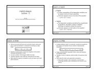
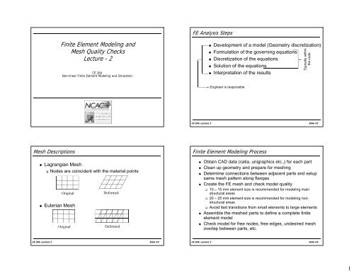
<strong>Mesh</strong> Descriptions<br />
<strong>Finite</strong> <strong>Element</strong> <strong>Modeling</strong> <strong>and</strong><br />
<strong>Mesh</strong> <strong>Quality</strong> <strong>Checks</strong><br />
<strong>Lecture</strong> <strong>Lecture</strong> - 22<br />
� Lagrangian <strong>Mesh</strong><br />
CE 264<br />
Non-linear <strong>Finite</strong> <strong>Element</strong> <strong>Modeling</strong> <strong>and</strong> Simulation<br />
� Nodes are coincident with the material points<br />
Original<br />
� Eulerian <strong>Mesh</strong><br />
Deformed<br />
Original Deformed<br />
CE 264, <strong>Lecture</strong> 2 Slide #3<br />
FE Analysis Steps<br />
� Development of a model (Geometry discretization)<br />
� Formulation of the governing equations<br />
within<br />
�� Discretization sc et at o oof tthe e equat equations o s<br />
lly<br />
� Solution of the equations<br />
� Interpretation of the results<br />
Engineer is responsible<br />
Typical<br />
the code<br />
CE 264, <strong>Lecture</strong> 2 Slide #2<br />
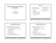
<strong>Finite</strong> <strong>Element</strong> <strong>Modeling</strong> Process<br />
� Obtain CAD data (catia, unigraphics etc.,) for each part<br />
� Clean up geometry <strong>and</strong> prepare for meshing<br />
� Determine connections between adjacent parts <strong>and</strong> setup<br />
same mesh pattern along flanges<br />
� Create the FE mesh <strong>and</strong> check model quality<br />
� 10 – 15 mm element size is recommended for modeling main<br />
structural areas<br />
� 20 – 25 mm element size is recommended for modeling nonstructural<br />
areas<br />
� Avoid fast transitions from small elements to large elements<br />
�� Assemble the meshed parts to define a complete finite<br />
element model<br />
� Check model for free nodes, free edges, undesired mesh<br />
overlap between parts, etc.<br />
CE 264, <strong>Lecture</strong> 2 Slide #4<br />
1
<strong>Modeling</strong> Guidelines – General<br />
� The element mesh should be orthogonal to the centerline<br />
of the part<br />
� The element mesh should be on the mid-plane of the<br />
cross section of the component thickness<br />
� The mid-plane is established by offsetting the geometry by<br />
1/2 of the gage thickness in the direction that the material is<br />
shown in the cross section of the drawing<br />
� No component thickness penetration or part intersection<br />
is allowed<br />
� <strong>Element</strong> size should be uniform whenever possible<br />
� Maintain a smooth transition from Coarse to Fine <strong>Mesh</strong><br />
CE 264, <strong>Lecture</strong> 2 Slide #5<br />
<strong>Modeling</strong> Guidelines – Flanges<br />
� Flanges of Crash models are to be modeled with<br />
three (3) elements across the flange<br />
� Two (2) elements can be used if the flange width is<br />
lless th than 15 mm<br />
CE 264, <strong>Lecture</strong> 2 Slide #7<br />
<strong>Modeling</strong> Guidelines – General<br />
� <strong>Element</strong> mesh is to be orthogonal to the centerline of the part<br />
� Transition <strong>Mesh</strong><br />
CE 264, <strong>Lecture</strong> 2 Slide #6<br />
<strong>Modeling</strong> Guidelines – Flanges<br />
� Bend radii less than 8mm are to be modeled as a<br />
sharp corner angle<br />
� Bend Radii greater than 8mm are to have a minimum<br />
of 2 elements elements, 1 node, node following the geometry<br />
CE 264, <strong>Lecture</strong> 2 Slide #8<br />
2
<strong>Modeling</strong> Guidelines – Beads <strong>and</strong> Ribs<br />
� Heights less than 3mm<br />
� ignore <strong>and</strong> mesh as flat<br />
� Heights between 3-5mm<br />
� increase the height to 5mm<br />
� Heights greater than 5mm<br />
� mesh as 3 equal length sides on the geometry<br />
CE 264, <strong>Lecture</strong> 2 Slide #9<br />
<strong>Modeling</strong> Guidelines – Notches<br />
� Notches greater than 20 mm l < 20 mm<br />
� Keep notch <strong>and</strong> split<br />
element to a minimum of 2<br />
across the width<br />
� Notches less than 20 mm<br />
� eliminate <strong>and</strong> replace with 2<br />
triangular elements<br />
� Notches less than 6 mm l < 6 mm<br />
� eliminate <strong>and</strong> replace with 2<br />
triangular g elements ( (larger g<br />
than 6 mm) →<br />
→<br />
CE 264, <strong>Lecture</strong> 2 Slide #11<br />
<strong>Modeling</strong> Guidelines – Holes<br />
� Holes<br />
� Holes with a diameter less<br />
than 10 mm are ignored<br />
� Holes with a diameter<br />
greater than h 10 mm are to<br />
be included<br />
� When meshing around<br />
holes, a minimum of 6<br />
elements is required<br />
d < 10 mm<br />
d > 10 mm<br />
CE 264, <strong>Lecture</strong> 2 Slide #10<br />
<strong>Modeling</strong> Guidelines – Transitions<br />
� <strong>Mesh</strong> Transition<br />
� Use triangular elements to<br />
transition<br />
�� Check aspect ratio of<br />
triangular elements<br />
� Triangular elements are<br />
stiffer than quad elements,<br />
particularly for coarse mesh<br />
� Use Co option in LS-DYNA<br />
(*CONTROL_SHELL, full<br />
sorting) ti )<br />
� Triangular elements.<br />
should be less than 10% of<br />
total elements<br />
→<br />
→<br />
<strong>Mesh</strong> Transition<br />
CE 264, <strong>Lecture</strong> 2 Slide #12<br />
3
<strong>Modeling</strong> Guidelines – Transitions<br />
2-D <strong>and</strong> 3-D <strong>Element</strong>s<br />
1-2 Transition 1-3 Transition<br />
CE 264, <strong>Lecture</strong> 2 Slide #13<br />
<strong>Modeling</strong> Guidelines – Special Shapes<br />
NOT DESIRABLE<br />
2-D <strong>and</strong> 3-D <strong>Element</strong>s<br />
DESIRABLE<br />
CE 264, <strong>Lecture</strong> 2 Slide #15<br />
<strong>Modeling</strong> Guidelines – Special Shapes<br />
� Special <strong>Mesh</strong> Shape<br />
� It is possible to use quad<br />
elements for triangular<br />
meshes<br />
Trapezoidal <strong>Mesh</strong><br />
2-D <strong>and</strong> 3-D <strong>Element</strong>s<br />
Triangular <strong>Mesh</strong><br />
CE 264, <strong>Lecture</strong> 2 Slide #14<br />
<strong>Modeling</strong> Guidelines – General<br />
2D <strong>and</strong> 3-D <strong>Element</strong>s<br />
� When modeling a sectional structure component<br />
� Use a minimum of 3 rows of elements to get a good in-plane<br />
bbending di<br />
� Use a minimum of 5 elements for a buckle<br />
CE 264, <strong>Lecture</strong> 2 Slide #16<br />
4
<strong>Modeling</strong> Guidelines – Solids<br />
� Solid <strong>Element</strong> Selection<br />
3-D <strong>Element</strong>s<br />
� Regular shaped 8-node brick is recommended (hexa)<br />
� Avoid 4, 5 <strong>and</strong> 7 node solid elements<br />
CE 264, <strong>Lecture</strong> 2 Slide #17<br />
<strong>Element</strong> <strong>Quality</strong> Check - Warpage<br />
CE 264, <strong>Lecture</strong> 2 Slide #19<br />
<strong>Element</strong> <strong>Quality</strong> Check<br />
� Warpage<br />
� Amount by which an element or element face (solid elements)<br />
deviates from being planar<br />
� Should be less than 15 0<br />
� Aspect Ratio<br />
� Ratio of the longest edge of an element to its shortest edge<br />
� Should be less than 5:1<br />
� Skew<br />
� Should be less than 60 0<br />
� Jacobian<br />
� Measure of the deviation of an element from an ideally shaped<br />
element<br />
� Ranges from 0 to 1.0, where 1.0 represents a perfectly shaped<br />
element<br />
� Should be greater than 0.6<br />
CE 264, <strong>Lecture</strong> 2 Slide #18<br />
<strong>Element</strong> <strong>Quality</strong> Check - Skew<br />
CE 264, <strong>Lecture</strong> 2 Slide #20<br />
5
Final <strong>Quality</strong> <strong>Checks</strong> – Shells<br />
CE 264, <strong>Lecture</strong> 2 Slide #21<br />
Final <strong>Quality</strong> <strong>Checks</strong><br />
� Align element NORMALS for each component in 1<br />
direction<br />
� BOUNDARY CHECK<br />
� SHELL ELEMENTS: No SPLITS or CRACKS allowed<br />
in the mesh<br />
� SOLID ELEMENTS: No interior SPLITS or CRACKS<br />
allowed in the mesh<br />
� Check for <strong>and</strong> eliminate DUPLICATE ELEMENTS<br />
� Check for <strong>and</strong> eliminate FREE 1-D ELEMENTS<br />
� Check for <strong>and</strong> eliminate RIGID DEPENDENCIES<br />
<strong>and</strong> RIGID LOOPS or CIRCULAR DEPENDENCIES<br />
CE 264, <strong>Lecture</strong> 2 Slide #23<br />
Final <strong>Quality</strong> <strong>Checks</strong> – Solids<br />
CE 264, <strong>Lecture</strong> 2 Slide #22<br />
Homework<br />
� http://crash.ncac.gwu.edu/pradeep/<br />
� Select CE-264<br />
�� Download Homework No No. 1 (HM file)<br />
� <strong>Mesh</strong> file using Hypermesh<br />
� Use element size of 10 mm<br />
� Check <strong>Mesh</strong> <strong>Quality</strong><br />
� Homework due Feb 24, 2009<br />
�� EE-mail mail Hypermesh ( (.hm) hm) file <strong>and</strong> <strong>Mesh</strong> <strong>Quality</strong> Form<br />
to pradeep@ncac.gwu.edu.<br />
CE 264, <strong>Lecture</strong> 2 Slide #24<br />
6