FEM-Design - Norconsult
FEM-Design - Norconsult
FEM-Design - Norconsult

You also want an ePaper? Increase the reach of your titles
YUMPU automatically turns print PDFs into web optimized ePapers that Google loves.
<strong>FEM</strong>-<strong>Design</strong> Plate<br />
With <strong>FEM</strong>-<strong>Design</strong> Plate, concrete slabs or other<br />
two-dimensional transversely loaded structures can be<br />
analysed.<br />
Reinforced concrete is designed according to code,<br />
accounting for cracked section analysis, shrinkage and<br />
creep considering calculated or applied reinforcement.<br />
Required reinforcement is calculated for ultimate or<br />
serviceability limit state, checking defl ections and/or<br />
crack width. Alternatively, reinforcement can be applied<br />
and checked according to code and defl ections and crack<br />
patterns displayed.<br />
<strong>FEM</strong>-<strong>Design</strong> Wall<br />
The Wall module offers design solutions for plane stress<br />
problems, such as shear and load bearing walls as well<br />
as for other kinds of structural elements such as webs of<br />
deep beams or steel plates.<br />
Concrete walls are designed according to EC2 and different<br />
national codes. <strong>Design</strong> forces are calculated as a<br />
combination of normal and shear stresses in the wall.<br />
Tension reinforcement requirements are calculated and a<br />
check is made that allowable compressive stresses in the<br />
concrete are not exceeded.<br />
Pre<strong>Design</strong><br />
The <strong>FEM</strong>-<strong>Design</strong> Pre<strong>Design</strong> module is used tp perform<br />
a pre-calculation for reaction and internal forces of load<br />
bearing walls and columns and to estimate material<br />
quantities for the entire structure.<br />
Automatic wind, snow and deviation load generation<br />
ensure fast and easy defi nition of the complete statical<br />
model which later can be opened in 3D Structure for indepth<br />
analysis and design.<br />
Villa Suprême, the head offi ce in Malmö, Sweden<br />
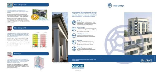
Structural <strong>Design</strong> Software in Europe AB (StruSoft)<br />
is a Swedish innovative software company with<br />
more than 25 years of experience in specialized<br />
software applications for the building industry.<br />
<strong>FEM</strong>-<strong>Design</strong><br />
An advanced 3D <strong>FEM</strong> software for analysis<br />
and design of complex structures with<br />
concrete, steel and timber elements.<br />
IMPACT Precast<br />
A BIM software for production of concrete<br />
precast elements. Based on AutoCAD ® and<br />
open database technology.<br />
IMPACT Reinforcement<br />
An AutoCAD ® -based application for<br />
detailing and scheduling reinforcement.<br />
WIN-Statik<br />
A series of powerful, but easy to use<br />
applications for common design tasks<br />
such as beams, columns or frames.<br />
VIP-Energy<br />
A series of software covering the<br />
calculation of the entire building energy<br />
balance.<br />
StruSoft’s mission is to increase the overall effi ciency in the<br />
Building Industry<br />
www.strusoft.com<br />
April 2009<br />
<strong>FEM</strong>-<strong>Design</strong><br />
www.strusoft.com
Features<br />
»<br />
»<br />
»<br />
»<br />
»<br />
»<br />
»<br />
»<br />
»<br />
»<br />
»<br />
»<br />
»<br />
»<br />
<strong>FEM</strong>-<strong>Design</strong> 3D Structure<br />
<strong>FEM</strong>-<strong>Design</strong> 3D Structure is an analysis and design software<br />
for complete structures containing a combination<br />
of shell elements, slabs, walls, bars, beams and columns<br />
with arbitrary loads.<br />
The steel and concrete modules allow code-specifi c<br />
design of all elements in the entire 3D-model.<br />
Static-, dynamic- and seismic analysis can be performed<br />
as well as solving global stability problems.<br />
Simple & user-friendly working environment<br />
Intelligent data connections via DXF, DWG and IFC<br />
as well as direct links from Tekla ® and Revit ® Structure<br />
Wizard for quick and easy input of slab and frame<br />
systems<br />
Point, line and surface supports with rigid, free or<br />
elastic stiffness components<br />
Relative constraints<br />
Section editor for defi ning sections for bars, beams<br />
and columns with arbitrary shapes<br />
Automatic generation of most unfavourable load<br />
combinations according to standards<br />
A powerful automatic optimal fi nite element mesh<br />
generator for any geometry<br />
No limit to the number of fi nite elements<br />
Peak smoothing<br />
Animation of displacement, vibration and stability<br />
results<br />
Analysis and steel design of straight bars with varying<br />
cross sections and bars with hollow space and<br />
stiffeners<br />
Steel design according to 2 nd order theory and<br />
imperfections<br />
Powerful concrete design and reinforcement<br />
checking<br />
Model<br />
The geometry is easily created in 3D with the use of intuitive<br />
tools such as axis and storey-system, region operation,<br />
user-defi ned views and user-coordinate-system.<br />
Underlays of CAD-fi les can be inserted as DWG or DXF.<br />
Complete 3D architectural or structural models can be<br />
imported via IFC model-based interface or from the direct<br />
links provided from Tekla ® and Revit ® Structure.<br />
Arbitrary shapes of shell elements can be created using<br />
solids and solid operations.<br />
Relative constraints allow connections between structural<br />
objects to be modelled accurately. This can be used for<br />
analyzing connection forces between prefabricated elements.<br />
As well as normal point, line and surface loads, temperature,<br />
stress, and seismic loads can also be defi ned.<br />
Analyse<br />
Static, dynamic (eigen frequencies), stability and seismic<br />
analysis can be carried out for the entire structure at<br />
once.<br />
The fi nite element mesh is automatically generated with<br />
optimal element sizes and automatic refi nements at supports<br />
and element connections, freeing the user to focus<br />
on the engineering task. There is no limit to the number<br />
of elements.<br />
A number of display methods can be used for viewing<br />
results including graphs, contour lines, colour palettes in<br />
3D for the whole structure, in 2D for each wall or slab,<br />
or as arbitrarily placed<br />
sections.<br />
Absolute or local maximum<br />
and minimum<br />
values can be displayed<br />
automatically, or the<br />
user can point anywhere<br />
on the structure to get a<br />
numeric result value.<br />
Analysis results for a T-section<br />
beam.<br />
<strong>Design</strong><br />
Steel design is carried out according to EC3 or several<br />
national codes using the steel design module (see 3D-<br />
Frame).<br />
Steel bars can automatically be converted to shell elements,<br />
allowing varying cross-sections, cut-outs and stiffeners,<br />
and checked for buckling shapes and utilisation for<br />
fl exural-, torsional-, lateral torsional- and local buckling.<br />
The powerful concrete module designs according to EC2<br />
or national codes accounting for shrinkage behaviour.<br />
Reinforcement can be designed according to defl ection<br />
and crack-width criteria as well as ultimate limit state<br />
design.<br />
Applied reinforcement in the concrete elements is<br />
checked according to code, and accurate crack-width<br />
and defl ection calculations can be made for specifi c reinforcement.<br />
Residential building in Vällingby, Sweden. Three 14 storey<br />
Concrete dome on commercial building in Dubai, UAE.<br />
buildings with challenging fl ag walls bearing 11 fl oors.<br />
Entrance to the underground train station at Triangeln, Above left: wind load defi nition. Above right: normal forces.<br />
<strong>FEM</strong>-<strong>Design</strong> 3D Structure was used to design walls and con-<br />
Malmö, Sweden. Integra Engineering AB AL HAWRAA Engineering Consultants for ICON Precast.<br />
nections. Ljustech Konsult AB<br />
Reinforcement design results for a T-section beam.<br />
Documentation<br />
One challenge of complex calculation projects is the<br />
presentation and documentation of results, whether for<br />
municipalities, clients or for archiving purposes.<br />
<strong>FEM</strong>-<strong>Design</strong> offers an easy and elegant way to create<br />
complete and conceivable documentation of projects<br />
containing a cover page with title table, chapters,<br />
fi gures, texts, tables, headers/footers, images and table<br />
of contents.<br />
Images are easily set up to display desired result, displaymode,<br />
scales and text size and are automatically<br />
refreshed when changes have been made to the model<br />
or calculation.<br />
Templates can be edited and stored in order to re-use<br />
standard styles for other projects.<br />
Results can also be exported to Microsoft ® Word and<br />
Excel.<br />
3D Frame<br />
<strong>FEM</strong>-<strong>Design</strong> 3D-Frame is an analysis and design software<br />
for three-dimensional frame and truss structures.<br />
Common structures can be generated along with<br />
loads in a few simple steps using the parametric input<br />
wizard. In the Section Editor, complex arbitrary section<br />
shapes (opened or closed) can be created for bars,<br />
beams and columns. All sectional parameters are automatically<br />
calculated for the current section.<br />
Using relative constraints, connections or intersections<br />
between elements can be modelled with ease. Eccentric<br />
3D bars or semi-rigid connection of columns and<br />
beams can be modelled in this way.<br />
The analysis includes 2 nd order analysis, dynamic analysis<br />
of eigenfrequencies and vibration modes, seismic<br />
calculations according to response spectra, stability and<br />
imperfection calculations.<br />
With “soft spring” procedures, an automatic check of<br />
insuffi cient supports and connections can be run to<br />
solve instable structures.<br />
Steel structures are designed according to EC3 or<br />
national codes. Steel bars can be checked with regard<br />
to 1 st or 2 nd order theory where imperfections are<br />
automatically calculated by connecting the 2 nd order<br />
analysis to one of the critical buckling modes. The design<br />
is performed for stresses, fl exural buckling, lateral<br />
torsional and torsional buckling, web buckling and<br />
fl ange buckling.<br />
Concrete design for 3D beams and columns is also<br />
available for EC2 and national codes.<br />
Steel design results. Above: code check for a HEA-beam.<br />
Above right: Buckling check for a shell element beam. Second entrance to the underground train station at Tri-<br />
Example of documentation output.<br />
angeln, Malmö, Sweden. Integra Engineering AB<br />
Utilization results for a complete structure and a single bar.