Finite Element Formulation for Plates - Handout 4 -
Finite Element Formulation for Plates - Handout 4 -
Finite Element Formulation for Plates - Handout 4 -

You also want an ePaper? Increase the reach of your titles
YUMPU automatically turns print PDFs into web optimized ePapers that Google loves.
<strong>Finite</strong> <strong>Element</strong> <strong>Formulation</strong> <strong>for</strong> <strong>Plates</strong><br />
- <strong>Handout</strong> 4 -<br />
Dr Fehmi Cirak (fc286@)<br />
Completed Version
Kinematics of Reissner-Mindlin Plate -1-<br />
■ The extension of Timoshenko beam theory to plates is the Reissner-Mindlin<br />
plate theory<br />
■ In Reissner-Mindlin plate theory the out-of-plane shear de<strong>for</strong>mations are<br />
non-zero (in contrast to Kirchhoff plate theory)<br />
■ Almost all commercial codes (Abaqus, LS-Dyna, Ansys, …) use Reissner-<br />
Mindlin type plate finite elements<br />
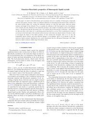
■ Assumed displacements during loading<br />
Page 72<br />
de<strong>for</strong>med<br />
reference<br />
unde<strong>for</strong>med and de<strong>for</strong>med geometries<br />
along one of the coordinate axis<br />
■ Kinematic assumption: a plane section originally normal to the mid-surface remains plane, but in<br />
addition also shear de<strong>for</strong>mations occur<br />
F Cirak
Kinematics of Reissner-Mindlin Plate -2-<br />
Page 73<br />
■ Kinematic equations<br />
■ In plane-displacements<br />
■ In this equation and in following all Greek indices only take values 1 or 2<br />
■ It is assumed that rotations are small<br />
■ Rotation angle of normal:<br />
■ Angle of shearing:<br />
■ Slope of midsurface:<br />
■ Out-of-plane displacements<br />
■ The independent variables of the Reissner-Mindlin plate theory are the<br />
rotation angle and mid-surface displacement<br />
■ Introducing the displacements into the strain equation of three-dimensional<br />
elasticity leads to the strains of the plate<br />
F Cirak
Weak Form of Reissner-Mindlin Plate -1-<br />
Page 74<br />
■ Axial strains and in-plane shear:<br />
■ Out-of-plane shear:<br />
■ Note that always<br />
■ Through-the-thickness strain:<br />
■ The plate strains introduced into the internal virtual work of threedimensional<br />
elasticity give the internal virtual work of the plate<br />
■ with virtual displacements and rotations:<br />
F Cirak
Weak Form of Reissner-Mindlin Plate -2-<br />
Page 75<br />
■ Definition of bending moments:<br />
■ Definition of shear <strong>for</strong>ces:<br />
■ External virtual work<br />
■ Distributed surface load<br />
■ Weak <strong>for</strong>m of Reissner-Mindlin plate<br />
■ As usual summation convention applies<br />
F Cirak
Weak Form of Reissner-Mindlin Plate -3-<br />
■ Constitutive equations<br />
Page 76<br />
■ For bending moments (same as Kirchhoff plate)<br />
■ For shear <strong>for</strong>ces<br />
■ Note that the curvature is a function of rotation angle<br />
and the shear angle is a function of rotation angle and the mid-surface displacement<br />
F Cirak
<strong>Finite</strong> <strong>Element</strong> Discretization -1-<br />
■ The independent variables in the weak <strong>for</strong>m are and the<br />
corresponding test functions<br />
Page 77<br />
■ Weak <strong>for</strong>m contains only so that C 0 -interpolation is sufficient<br />
■ Usual (Lagrange) shape functions such as used in 3D7 can be used<br />
■ Nodal values of variables:<br />
■ Nodal values test functions:<br />
■ Interpolation equations introduced into the kinematic equations yield<br />
four-node isoparametric<br />
element<br />
F Cirak
<strong>Finite</strong> <strong>Element</strong> Discretization -2-<br />
Page 78<br />
■ Constitutive equations in matrix notation<br />
■ Bending moments:<br />
■ Shear <strong>for</strong>ces:<br />
■ <strong>Element</strong> stiffness matrix of a four-node quadrilateral element<br />
■ Bending stiffness (12x12 matrix)<br />
F Cirak
<strong>Finite</strong> <strong>Element</strong> Discretization -3-<br />
Page 79<br />
■ Shear stiffness (12x12 matrix)<br />
■ <strong>Element</strong> stiffness matrix<br />
■ The integrals are evaluated with numerical integration. If too few integration points are used,<br />
element stiffness matrix will be rank deficient.<br />
■ The necessary number of integration points <strong>for</strong> the bilinear element are 2x2 Gauss points<br />
■ The global stiffness matrix and global load vector are obtained by<br />
assembling the individual element stiffness matrices and load<br />
vectors<br />
■ The assembly procedure is identical to usual finite elements<br />
F Cirak
Shear Locking Problem -1-<br />
■ As discussed <strong>for</strong> the Bernoulli and Timoshenko beams with increasing plate<br />
slenderness physics dictates that shear de<strong>for</strong>mations have to vanish<br />
(i.e., )<br />
Page 80<br />
■ Reissner-Mindlin plate and Timoshenko beam finite elements have problems to approximate<br />
de<strong>for</strong>mation states with zero shear de<strong>for</strong>mations (shear locking problem)<br />
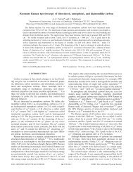
■ 1D example: Cantilever beam with applied tip moment<br />
■ Bending moment and curvature constant along the beam<br />
■ Shear <strong>for</strong>ce and hence shear angle zero along the beam<br />
■ Displacements quadratic along the beam<br />
■ Discretized with one two-node Timoshenko beam element<br />
F Cirak
Shear Locking Problem -2-<br />
Page 81<br />
■ Deflection interpolation:<br />
■ Rotation interpolation:<br />
■ Shear angle:<br />
■ For the shear angle to be zero along the beam, the displacements and rotations have to be zero. Hence, a<br />
shear strain in the beam can only be reached when there are no de<strong>for</strong>mations!<br />
■ Similarly, en<strong>for</strong>cing at two integration points leads to zero<br />
displacements and rotations!<br />
■ However, en<strong>for</strong>cing only at one integration point (midpoint of the<br />
beam) leads to non-zero displacements<br />
■ In the following several techniques will be introduced to circumvent the<br />
shear locking problem<br />
■ Use of higher-order elements<br />
■ Uni<strong>for</strong>m and selective reduced integration<br />
■ Discrete Kirchhoff elements<br />
■ Assumed strain elements<br />
F Cirak
Constraint Ratio (Hughes et al.) -1-<br />
■ Constraint ratio is a semi-heuristic number <strong>for</strong> estimating an element’s<br />
tendency to shear lock<br />
■ Continuous problem<br />
■ Number of equilibrium equations: 3 (two <strong>for</strong> bending moments + one <strong>for</strong> shear <strong>for</strong>ce)<br />
■ Number of shear strain constraints in the thin limit: 2<br />
Page 82<br />
■ Constraint ratio:<br />
■ With four-node quadrilateral finite elements discretized problem<br />
■ Number of degrees of freedom per element on a very large mesh is ~3<br />
■ Number of constraints per element <strong>for</strong> 2x2 integration per element is 8<br />
■ Constraint ratio:<br />
■ Number of constraints per element <strong>for</strong> one integration point per element is 2<br />
■ Constraint ratio:<br />
F Cirak
Constraint Ratio (Hughes et al.) -2-<br />
Page 83<br />
■ Constraint ratio <strong>for</strong> a 9 node element<br />
■ Number of degrees of freedom per element on a very large mesh is ~ 4x3 =12<br />
■ Number of constraints per element <strong>for</strong> 3x3 integration is 18<br />
■ Constraint ratio:<br />
■ Constraint ratio <strong>for</strong> a 16 node element<br />
■ Number of degrees of freedom per element on a very large mesh is ~ 9x3=27<br />
■ Number of constraints per element <strong>for</strong> 4x4 integration is 32<br />
■ Constraint ratio:<br />
■ As indicated by the constraint ratio higher-order elements are less likely to<br />
exhibit shear locking<br />
F Cirak
Uni<strong>for</strong>m And Selective Reduced Integration -1-<br />
■ The easiest approach to avoid shear “locking” in thin plates is to use<br />
some <strong>for</strong>m of reduced integration<br />
Page 84<br />
■ In uni<strong>for</strong>m reduced integration the bending and shear terms are integrated with the<br />
same rule, which is lower than the “normal”<br />
■ In selective reduced integration the bending term is integrated with the normal rule and<br />
the shear term with a lower-order rule<br />
■ Uni<strong>for</strong>m reduced integrated elements have usually rank deficiency<br />
(i.e. there are internal mechanisms; de<strong>for</strong>mations which do not need<br />
energy)<br />
■ The global stiffness matrix is not invertible<br />
■ Not useful <strong>for</strong> practical applications<br />
F Cirak
Uni<strong>for</strong>m And Selective Reduced Integration -2-<br />
Page 85<br />
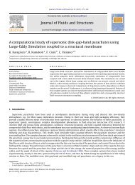
Shape functions<br />
Uni<strong>for</strong>m reduced<br />
integration<br />
Selective reduced<br />
integration<br />
Bilinear<br />
1x1<br />
1x1 shear<br />
2x2 bending<br />
Biquadratic<br />
■ “Shear” refers to the integration of the element shear stiffness matrix<br />
■ “Bending” refers to the integration of the element bending stiffness matrix<br />
Bicubic<br />
2x2 3x3<br />
2x2 shear<br />
3x3 bending<br />
3x3 shear<br />
4x4 bending<br />
F Cirak
Discrete Kirchhoff <strong>Element</strong>s<br />
■ The principal approach is best illustrated with a Timoshenko beam<br />
■ The displacements and rotations are approximated with quadratic shape<br />
functions<br />
■ The inner variables are eliminated by en<strong>for</strong>cing zero shear stress at the two<br />
gauss points<br />
■ Back inserting into the interpolation equations leads to a beam<br />
element with 4 nodal parameters<br />
Page 86<br />
F Cirak
Assumed Strain <strong>Element</strong>s<br />
■ It is assumed that the out-of-plane shear strains at edge centres are of<br />
“higher quality” (similar to the midpoint of a beam)<br />
Page 87<br />
■ First, the shear angle at the edge centres<br />
is computed using the displacement and rotation nodal values<br />
■ Subsequently, the shear angles from the edge centres are interpolated back<br />
■ Note that the shape functions are special edge shape functions<br />
■ These reinterpolated shear angles are introduced into the weak <strong>for</strong>m and are <strong>for</strong> element stiffness<br />
matrix computation used<br />
F Cirak