Smith Model LT-11 Bulk Flowmetering System - National ...
Smith Model LT-11 Bulk Flowmetering System - National ...
Smith Model LT-11 Bulk Flowmetering System - National ...

Create successful ePaper yourself
Turn your PDF publications into a flip-book with our unique Google optimized e-Paper software.
12 Lyonpark Road, North Ryde NSW 2<strong>11</strong>3<br />
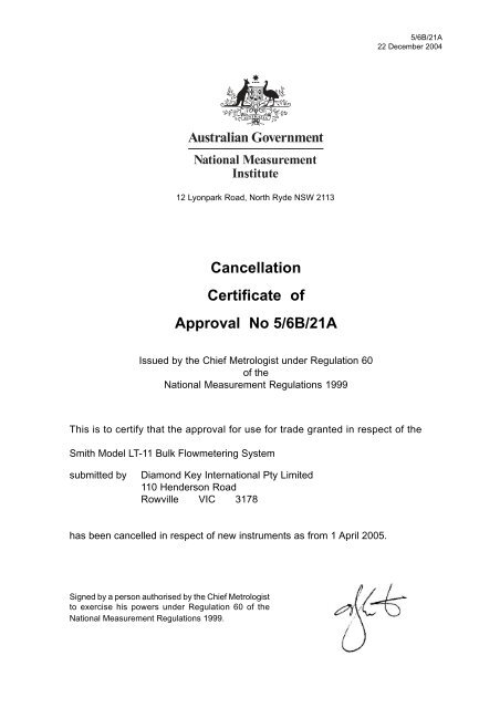
Cancellation<br />
Certificate of<br />
Approval No 5/6B/21A<br />
Issued by the Chief Metrologist under Regulation 60<br />
of the<br />
<strong>National</strong> Measurement Regulations 1999<br />
5/6B/21A<br />
22 December 2004<br />
This is to certify that the approval for use for trade granted in respect of the<br />
<strong>Smith</strong> <strong>Model</strong> <strong>LT</strong>-<strong>11</strong> <strong>Bulk</strong> <strong>Flowmetering</strong> <strong>System</strong><br />
submitted by Diamond Key International Pty Limited<br />
<strong>11</strong>0 Henderson Road<br />
Rowville VIC 3178<br />
has been cancelled in respect of new instruments as from 1 April 2005.<br />
Signed by a person authorised by the Chief Metrologist<br />
to exercise his powers under Regulation 60 of the<br />
<strong>National</strong> Measurement Regulations 1999.
<strong>National</strong> Standards Commission<br />
Certificate of Approval<br />
No 5/6B/21 A<br />
Issued under Regulation 9<br />
of the<br />
<strong>National</strong> Measurement (Patterns of Measuring Instruments) Regulations<br />
5/6Bl2lA<br />
31/l/94<br />
This is to certify that an approval for use for trade has been granted in respect of<br />
the<br />
<strong>Smith</strong> <strong>Model</strong> <strong>LT</strong>-<strong>11</strong> <strong>Bulk</strong> <strong>Flowmetering</strong> <strong>System</strong><br />
submitted by Email Electronics<br />
88-94 Canterbury Road<br />
Kilsyth VIC 3137.<br />
This Certificate is issued upon completion of reviews of NSC approvals Nos<br />
5/68/21, 5/6B/26, 5168127, 5/6B/33 and 5/6D/22.<br />
NOTE: This Certificate relates to the suitability of the pattern of the instrument for<br />
use for trade only in respect of its metrological characteristics. This Certificate<br />
does not constitute or imply any guarantee of compliance by the manufacturer or<br />
any other person with any requirements regarding safety.<br />
CONDITIONS OF APPROVAL<br />
This approval is subject to review on or after l/10/97.<br />
This approval expires in respect of new instruments on l/l O/98.<br />
. . ..I2
Certificate of Approval No 5/68/21A Page 2<br />
Instruments purporting to comply with this approval shall be marked<br />
NSC No 5/68/21A and only by persons authorised by the submittor.<br />
It is the submittor’s responsibility to ensure that all instruments marked with this<br />
approval number are constructed as described in the documentation lodged with<br />
the Commission and with the relevant Certificate of Approval and Technical<br />
Schedule. Failure to comply with this Condition may attract penalties under<br />
Section 19B of the <strong>National</strong> Measurement Act and may result in cancellation or<br />
withdrawal of the approval, in accordance with the Commission’s Document 106.<br />
The Commission reserves the right to examine any instrument or component of an<br />
instrument purporting to comply with this approval.<br />
Auxiliary devices used with this instrument shall comply with the requirements of<br />
General Supplementary Certificate No S1/0/A.<br />
Pattern: approved 2819192<br />
DESCRIPTIVE ADVICE<br />
. A bulk flowmetering system using a <strong>Smith</strong> model <strong>LT</strong>-<strong>11</strong> flowmeter which is<br />
approved for use with liquids having a kinematic viscosity between 0.5 and<br />
12.5 mm*/s.<br />
Variants: approved 2819192<br />
1. As a loading-rack flowmetering system.<br />
2. As a modular flowmetering system.<br />
3. As a drum-filling flowmetering system.<br />
4. As a bulk flowmetering system using certain other <strong>Smith</strong> flowmeters.<br />
5. For use with liquids having a kinematic viscosity between 12.5 and 1450<br />
mm*/s.<br />
6. For use with bituminous products having a kinematic viscosity between 5<br />
and 25 mm*/s.<br />
Technical Schedule No 5/6B/21A describes the pattern and variants 1 to 6.<br />
. . ..I3
5l6W27 A<br />
37/7/94<br />
Certificate of Approval No 5/6B/21 A Page 3<br />
FILING ADVICE<br />
The documentation for this approval comprises:<br />
Certificate of Approval No 5/6B/21 A dated 31 /l/94<br />
Technical Schedule No 5/68/21A dated 31/l/94 (incl. Table 1 and Test<br />
Procedure)<br />
Figures 1 to 6 dated 31/l/94<br />
Signed and sealed by a person authorised under<br />
Regulation 9 of the <strong>National</strong> Measurement<br />
(Patterns of Measuring Instruments) Regulations<br />
to exercise the powers and functions of the<br />
Commission under this Regulation.
<strong>National</strong> Standards Commission<br />
TECHNICAL SCHEDULE No 5/6B/21A<br />
Pattern: <strong>Smith</strong> <strong>Model</strong> <strong>LT</strong>-<strong>11</strong> <strong>Bulk</strong> <strong>Flowmetering</strong> <strong>System</strong>.<br />
Submittor: Email Electronics<br />
88-94 Canterbury Road<br />
Kilsyth Victoria 3137.<br />
1. Description of Pattern<br />
A bulk flowmetering system using a <strong>Smith</strong> model <strong>LT</strong>-<strong>11</strong> flowmeter<br />
approved for use with liquids having a kinematic viscosity between<br />
12.5 mm*/s.<br />
5/68/27A<br />
3717194<br />
which is<br />
0.5 and<br />
The system is approved for use for a flow rate range of 37 Umin to 300 Umin for<br />
normal operation, but may be used for short periods up to an eXtendeCl maximum<br />
flow rate of 375 L/min.<br />
The minimum quantity is 100 litres.<br />
1.1 Pipeline <strong>Flowmetering</strong> <strong>System</strong> (Figure 1)<br />
(i)<br />
Tank<br />
A supply tank.<br />
(ii) Pump<br />
A pump of either positive displacement or centrifugal type - in the latter case the<br />
pump is mounted lower than the minimum height of the liquid in the supply tank.<br />
The supply pipe from the tank has a continuous fall to the pump.<br />
If the pump is not for the exclusive use of the flowmeter the flow rate through the<br />
meter must stay within the appropriate flow rate range for all combinations of<br />
alternative uses of the pump.<br />
(iii) Non-return Valve<br />
A non-return valve between the pump and the meter or an arrangement of the<br />
components and piping to keep the system full of liquid at all times.<br />
(iv)<br />
Gas Purger/Strainer<br />
A gas purger/strainer assembly fitted as close as practical to the meter inlet<br />
(Figure 2). The gas purger is approved on the condition that the pump is operated<br />
under a positive suction head.<br />
. . ..I2
S/60/27 A<br />
37/7/94<br />
Technical Schedule No 5/6B/21 A Page 2<br />
The gas purger/strainer assembly may be modified for use as a strainer only<br />
where the tank has automatic alarming of low-liquid level, or has a float-operated<br />
shut-off valve in the pump supply, or has other means to prevent gas entering the<br />
system.<br />
64<br />
Meter<br />
A <strong>Smith</strong> model <strong>LT</strong>-<strong>11</strong> flowmeter (Figure 2). May also be known as a model T-l 1.<br />
Provision shall be made for a pressure gauge to be connected downstream of the<br />
meter.<br />
(vi)<br />
Indicating <strong>System</strong><br />
Any of the following assemblies:<br />
(a)<br />
04<br />
(c)<br />
((3<br />
(e><br />
u 1<br />
(9)<br />
A Veeder-Root 1624 series or 7887 series zero start indicator with or<br />
without (d).<br />
A Veeder-Root 7085 series or 7890 series zero-start indicator (Figure 2)<br />
with ticket printer with or without (d).<br />
A <strong>Smith</strong> model 343-30 or Veeder-Root 7889 series preset counter<br />
(Figure 2) with a <strong>Smith</strong> preset-counter-operated outlet control valve; a<br />
pressure relief pipe may be fitted between the valve and the gas<br />
purger/strainer. The preset counter is marked PRESET NOT IN USE<br />
FOR TRADE.<br />
A Commission-approved <strong>Smith</strong> model ATC or model ATG mechanical<br />
volume conversion for temperature device (as described in the<br />
documentation of NSC approvals Nos S146A and S147A, respectively).<br />
A rigid extension drive from the meter to the indicator and ticket printer.<br />
A <strong>Smith</strong> model SS1 flow controller (NSC No S190).<br />
Any compatible Commission-approved pulse generator, electronic bulk<br />
flowmeter controller/indicator and flow control valve.<br />
NOTE: Where systems include a pulse generator and electronic indicator, the<br />
pulse generator shall be driven directly from the output shaft of the meter; it shall<br />
not be driven via a mechanical indicator nor via reduction gear trains.<br />
The use of a right-angled drive would be considered as direct as long as the drive<br />
consists of two bevel gears with a I:1 ratio and provided the right-angled drive is<br />
before the drive to any mechanical indicator.<br />
Where the pulse generator is not driven directly, any electronic indicator<br />
connected to it shall be marked NOT IN USE FOR TRADE.<br />
. . ..I3
-<br />
5/6Bl27 A<br />
37/7/94<br />
Technical Schedule No 5/68/21A Page 3<br />
(vii) Transfer Device<br />
A transfer device in the form of a positive shut-off component such as a manually<br />
or automatically-operated control valve located downstream of the meter with no<br />
intermediate outlet.<br />
1.2 Markings<br />
Instruments are marked with the following data, together in the one location:<br />
Manufacturer’s name or mark<br />
Meter model<br />
Serial number<br />
NSC approval number<br />
Maximum flow rate<br />
Minimum flow rate<br />
Minimum quantity<br />
Type of liquid for which the meter is verified<br />
Maximum operating pressure<br />
516 B/2 1 A<br />
. . . . . Umin<br />
. . . . . Umin<br />
. . . . . L<br />
. . . . . #<br />
. . . . . kPa<br />
# May be located separately, e.g. on a metal tag sealed to the<br />
instrument.<br />
In addition, preset counters (other than on drum-filling flowmeters complying with<br />
clause 2.3 Variant 3) shall be marked PRESET NOT IN USE FOR TRADE.<br />
1.3 Sealing and Verification/Certification Provision<br />
Provision is made for sealing the calibration device of the meter. Provision is also<br />
made for a verification/certification mark to be applied.<br />
2. Description of Variants<br />
2.1 Variant 1<br />
As a loading-rack flowmetering system (Figure 3) which is similar to the pipeline<br />
system except that the control valve is installed at or upstream of the transfer<br />
device, which is one of the following:<br />
U) Top-loading arrangement - the highest point of the pipework forms a weir<br />
at a fixed level from which the delivery pipe drains to the outlet for all<br />
configurations of the hose or loading arm whilst in operation. A syphon<br />
breaker is installed to ensure complete draining of the pipework<br />
downstream of the weir.<br />
. . ..I4
5/6B/21A<br />
31/l/94<br />
Technical Schedule No 5/66/21A Paae 4<br />
Alternatively, an anti-drain valve which retains a pressure of not less than<br />
55 kPa may be installed at the delivery point of the pipework or hose; or<br />
(ii) Bottom-loading arrangement - a dry-break coupling located at the delivery<br />
point of the pipework or hose.<br />
2.2 Variant 2<br />
As a modular flowmetering system (Figure 4) which is similar to the pipeline and<br />
loading-rack systems, except that it is a module of metering components in its own<br />
assembly rather than built into another structure. It may be portable, including<br />
being vehicle-mounted.<br />
The system consists of a gas purger/strainer, a meter and a transfer device. It<br />
may contain the pump, together with a pressure control valve (if necessary), and a<br />
hose reel; in the latter case, the transfer device is in the form of either a nozzle or<br />
dry-break coupling at the end of a flexible hose.<br />
The pump is located lower than the minimum height of the liquid in the supply tank.<br />
A non-return valve is located between the pump and the meter, or the components<br />
and piping are arranged to keep the system full of liquid at all times.<br />
Any nozzle used shall have an integral outlet control valve. If fitted with an integral<br />
anti-drain valve, the valve shall be immediately before the outlet control valve. A<br />
separate anti-drain valve may be fitted to the nozzle end of the hose if an integral<br />
anti-drain valve is not part of the nozzle. The anti-drain valve retaining pressure<br />
shall be not less than 55 kPa.<br />
2.3 Variant 3<br />
As a drum-filling flowmetering system (Figure 5) which is similar to the pipeline and<br />
loading-rack systems except for the following:<br />
6) The system uses a <strong>Smith</strong> model <strong>LT</strong>-<strong>11</strong> H flowmeter (Figure 6) which is<br />
approved for use at maximum and minimum flow rates of 220 L/min and<br />
160 L/min respectively. The minimum quantity is 50 litres.<br />
(ii) The meter is fitted with a <strong>Smith</strong> model 502 counter and a <strong>Smith</strong> outlet<br />
control valve with integral anti-drain valve. The valve may be closed<br />
manually or by the 502 counter. A pressure relief pipe is fitted between<br />
the valve and the gas purger/strainer.<br />
The indicator is approved to repeat deliveries of 60, 200 or 205 litres, and<br />
is marked PRESET FOR ‘#’ LITRES (where ‘#’ equals one of the<br />
approved preset quantities). Unlike the pattern, the preset counter of this<br />
variant need NOT be marked PRESET NOT IN USE FOR TRADE.<br />
. . ..I5
5/68/21A<br />
31/l/94<br />
Technical Schedule No 5/6B/21A Paae 5<br />
(iii) The system is arranged such that the meter operates at a constant flow<br />
rate (f5% of nominal) within the maximum and minimum flow rate range.<br />
(iv) The outlet is either a drum-filling spear or a hose. If a spear is used, it is<br />
arranged to fully drain after each delivery so that the control valve is the<br />
transfer device. If a hose is used, it is fitted with a model F13931 nozzle<br />
which has an anti-drain valve installed either in the nozzle or immediately<br />
before it, and having a retaining pressure of not less than 55 kPa; the<br />
nozzle is the transfer device.<br />
2.4 Variant 4<br />
A bulk flowmetering system using any <strong>Smith</strong> flowmeter listed below. These<br />
systems are not approved for drum-filling.<br />
TABLE 1<br />
Meter Flow Rate Umin Minimum<br />
<strong>Model</strong> Maximum (#) Minimum Quantity L<br />
<strong>LT</strong>-<strong>11</strong> 300 (375) 37 100<br />
<strong>LT</strong>-20 750 (900) 100 200<br />
<strong>LT</strong>-40 1500 (1900) 190 300<br />
SC-13 475 (570) 57 100<br />
ST-40 400 (n/a) 40 50<br />
ST-75 1000 (n/a) 100 100<br />
ST-1 60 1600 (n/a) 160 200<br />
l-75 285 (n/a) 57 100<br />
I-150 570 (n/a) <strong>11</strong>4 200<br />
NOTE: Meters with the prefixes <strong>LT</strong> may drop the L prefix and/or have suffixes such as<br />
H,P,R,T,V,XorZ, asinT-<strong>11</strong> or<strong>LT</strong>-1lZ.<br />
w The value given in brackets ( ) for maximum flow rate is the extended maximum flow rate<br />
value for use over short periods only.<br />
2.5 Variant 5<br />
For use with liquids having a kinematic viscosity between 12.5 and 1450 mm*/s.<br />
. . ..I6
5/68/21A<br />
31/l/94<br />
Technical Schedule No 5/68/21A Page 6<br />
2.6 Variant 6<br />
For use with bituminous products at temperatures between 170 and 21 OOC, having<br />
a kinematic viscosity between 5 and 25 mm2/s. Instruments are used with a<br />
Commission-approved <strong>Smith</strong> model ATC or model ATG mechanical volume<br />
conversion for temperature device and any of the mechanical indicators as<br />
described for the pat!ern; alternatively, any compatible Commission-approved<br />
pulse generator and electronic bulk flowmeter controller/indicator. (NOTE: The<br />
pulse generator and the volume conversion facility of the indicator MUST be<br />
Commission-approved for the temperature range specified above.)<br />
TEST PROCEDURE<br />
Instruments should be tested in accordance with the Inspector’s Handbook using<br />
the product with which they will be used and which is marked on the data plate.<br />
Tests should be conducted in conjunction with any tests specified in the approval<br />
documentation for any indicator and/or conversion device, etc. used.<br />
Maximum Permissible Errors at Verification/Certification<br />
The maximum permissible error applied during a verification test from normal flow<br />
rate to the minimum flow rate specified in the Certificate of Approval or Technical<br />
Schedule is &0.3%.<br />
Where an instrument is fitted with a device to convert the registered volume to<br />
volume at reference conditions, the maximum permissible error specified above is<br />
increased by 0.2%. Reference conditions for petroleum liquids are specified in<br />
Australian Standard 2649 - 1983, Petroleum Liquids and Gases - Measurement<br />
- Standard Reference Conditions.<br />
1. Meter Tests for Bitumen, Lube Oil, or other products of similar viscosity<br />
The following is the recommended test procedure for the verification of meters<br />
used for measuring bituminous products, and requires a verified weighbridge.<br />
Notes:<br />
(4<br />
The density of the metered product may vary due to the amount of additives<br />
introduced and a density value (mass/unit volume) at l!TC of the product being<br />
used for test should be obtained before testing commences. Conversion factors<br />
for registered volume to volume at l!Y’C are available from the Commission.<br />
(b) The procedure does not take into account the closeness of a suitable<br />
weighbridge; should the weighbridge not be in the vicinity of the meter or filling<br />
point, then either an allowance must be made for fuel used or, preferably, the<br />
tanker’s fuel tanks should be topped up before each weighing, either at the<br />
terminal or near the weighbridge. This provides a constant value for the tare<br />
weight of the tanker at all weighings.<br />
. . . . I7
S/68/21 A<br />
31/l/94<br />
Technical Schedule No 5/68/2lA Page 7<br />
w<br />
The method of measurement indicated above introduces additional uncertainties<br />
which may be of a similar order to the maximum permissible error for repeatability<br />
when the scale interval is approximately equal to a weight equivalent to more than<br />
0.1% of the test volume delivered. These uncertainties need to be considered<br />
when assessing the performance of the meter under test.<br />
(4 The weighbridge shall have been calibrated not more than six weeks before<br />
testing the meter, with particular attention paid to points in the loading curve<br />
approximately equal to the tare of the tanker, tare plus one test delivery from the<br />
meter and tare plus two test deliveries. A scale interval should be used which is<br />
as small as possible, preferably equal to a weight equivalent to less than 0.1% of<br />
the test volume of product delivered.<br />
- Test Method<br />
(0<br />
(ii)<br />
Determine the tare weight of the tanker.<br />
Make a delivery into the tanker of approximately 40% of its maximum<br />
capacity at its nominal flow rate, noting:<br />
. Average product temperature (1);<br />
. Average flow rate;<br />
. Converted registered volume at completion of the delivery (Vr,); and<br />
. Un-converted registered volume at completion of the delivery (Vr,).<br />
(iii) Weigh the tanker and record the gross weight. The weight of the volume<br />
delivered is equal to the net weight. The volume at 15OC (Vd15) is found<br />
from, the net weight using Table 56 of the ASTM-IP Tables and the density<br />
at 15OC.<br />
(iv)<br />
The volume delivered (Vd,) at the product temperature (t) is found from<br />
the volume at 15OC by using volume conversion factors available from the<br />
Commission.<br />
Repeat steps (ii) and (iii) and, where the flow rate varies in use by more<br />
than +lO% of nominal, repeat twice at the maximum and minimum flow<br />
rates.<br />
(4 The error for the converted volume (e,) is found as follows:<br />
Vr,-Vd15<br />
e, = x 100%<br />
V&5<br />
The error for the unconverted volume (e,) is found as follows:<br />
Vr, - Vdr<br />
e, = x 100%<br />
Vdt
<strong>National</strong> Standards Commission<br />
Notification of Change<br />
Certificate of Approval No 5/6B/21A<br />
Change No 1<br />
5/6B/21A<br />
13 December 1998<br />
The following changes are made to the approval documentation for the<br />
<strong>Smith</strong> <strong>Model</strong> <strong>LT</strong>-<strong>11</strong> <strong>Bulk</strong> <strong>Flowmetering</strong> <strong>System</strong><br />
submitted by Email Electronics<br />
88-94 Canterbury Road<br />
Kilsyth VIC 3137.<br />
(a) In Certificate of Approval No 5/6B/21A and its Technical<br />
Schedule, both dated 31 January 1994, all references to the submittor<br />
should be amended to read;<br />
Diamond Key International Pty Limited<br />
<strong>11</strong>0 Henderson Road<br />
Rowville VIC 3178.<br />
(b) In Certificate of Approval No 5/6B/21A dated 31 January 1994, the Condition<br />
of Approval referring to the expiry of the approval should now be deleted.<br />
Signed and sealed by a person authorised<br />
under Regulation 9 of the <strong>National</strong><br />
Measurement (Patterns of Measuring<br />
Instruments) Regulations to exercise the<br />
powers and functions of the Commission<br />
under this Regulation.
L<br />
516Bi21 A<br />
31/l/94
5lEV21A<br />
31/<strong>11</strong>94<br />
N
c<br />
iii<br />
F<br />
a’<br />
8<br />
0<br />
5/68/21A<br />
31/l/94
5/60i2lA<br />
31/l/94
5/68/21A<br />
31m94