

Smith Meter ® AccuLoad III ® - Measurement Solutions
Smith Meter ® AccuLoad III ® - Measurement Solutions
Smith Meter ® AccuLoad III ® - Measurement Solutions

Create successful ePaper yourself
Turn your PDF publications into a flip-book with our unique Google optimized e-Paper software.
<strong>AccuLoad</strong> <strong>III</strong> AccuMate<br />
<strong>Smith</strong> <strong>Meter</strong> <strong>®</strong> <strong>AccuLoad</strong> <strong>III</strong> <strong>®</strong><br />
Installation/Operation<br />
Issue/Rev. 0.5 (3/11) Bulletin MN06136<br />
The Most Trusted Name in <strong>Measurement</strong>
Caution<br />
The default or operating values used in this manual and in the program of the <strong>AccuLoad</strong> <strong>III</strong> are for factory<br />
testing only and should not be construed as default or operating values for your metering system. Each metering<br />
system is unique and each program parameter must be reviewed and programmed for that specific metering system<br />
application.<br />
Disclaimer<br />
FMC Technologies <strong>Measurement</strong> <strong>Solutions</strong>, Inc. hereby disclaims any and all responsibility for damages, including<br />
but not limited to consequential damages, arising out of or related to the inputting of incorrect or improper program<br />
or default values entered in connection with the <strong>AccuLoad</strong> <strong>III</strong>.
Table of Contents<br />
Section I – Introduction .............................................................................................................................................1<br />
Product Description ..............................................................................................................................................1<br />
Modes of Operation ..............................................................................................................................................1<br />
Offline Mode ....................................................................................................................................................1<br />
Read Only Mode ..............................................................................................................................................1<br />
Online Mode ....................................................................................................................................................1<br />
Online Help ..........................................................................................................................................................1<br />
Section II – Installation .............................................................................................................................................2<br />
Installing AccuMate ..............................................................................................................................................2<br />
Program Files .......................................................................................................................................................2<br />
AccuMate for <strong>AccuLoad</strong> <strong>III</strong>-X ...........................................................................................................................2<br />
File Extensions .....................................................................................................................................................2<br />
Section <strong>III</strong> – Communications ...................................................................................................................................3<br />
Establishing Communications ..............................................................................................................................3<br />
Communication Cable Wiring ...............................................................................................................................3<br />
Communications Port Setup ................................................................................................................................3<br />
Communications Port Setup – Ethernet ...............................................................................................................3<br />
Initiating Communications with the <strong>AccuLoad</strong> <strong>III</strong> ..................................................................................................4<br />
Troubleshooting ....................................................................................................................................................5<br />
Using <strong>Smith</strong> <strong>Meter</strong>'s Virtual Load Rack with AccuMate .......................................................................................5<br />
Using the Terminal Emulator ................................................................................................................................5<br />
Section IV – Operations ............................................................................................................................................6<br />
Program Startup ...................................................................................................................................................6<br />
Data and Functions ..............................................................................................................................................6<br />
File Menu .........................................................................................................................................................6<br />
Edit Menu .........................................................................................................................................................6<br />
Tools Menu.......................................................................................................................................................8<br />
Options Menu ..................................................................................................................................................9<br />
Window Menu ..................................................................................................................................................9<br />
Using the Wizard to Configure New Files ...........................................................................................................10<br />
Editing Program Code Data ................................................................................................................................13<br />
Report Editor ......................................................................................................................................................17<br />
Advanced Report Options ..................................................................................................................................19<br />
Use Alternate Print Format ............................................................................................................................20<br />
Reference Register ........................................................................................................................................20<br />
Use Reference Register Value as Offset for this Item ....................................................................................20<br />
Restrictions ....................................................................................................................................................20<br />
i
Table of Contents<br />
Sample Report ...................................................................................................................................................21<br />
Translation Editor ................................................................................................................................................23<br />
Translating Literals for English to Languages Using Non-Western Characters .............................................26<br />
Section V – Programmable and Boolean Statements .............................................................................................29<br />
AccuMate Equation Editor ..................................................................................................................................29<br />
Boolean/Algebraic Statements ...........................................................................................................................30<br />
Specific Boolean Expressions ............................................................................................................................32<br />
Setting a Timer ...............................................................................................................................................32<br />
Setting an Alarm ............................................................................................................................................32<br />
Inputs and Outputs ........................................................................................................................................32<br />
Possible Boolean Applications ............................................................................................................................33<br />
Algebraic Expressions ........................................................................................................................................36<br />
Coefficient of Expansion Calculator....................................................................................................................37<br />
ii
Product Description<br />
AccuMate for <strong>AccuLoad</strong> <strong>III</strong> is a Windows application that<br />
facilitates configuration of the <strong>Smith</strong> <strong>Meter</strong> <strong>®</strong> <strong>AccuLoad</strong> <strong>III</strong><br />
series of electronic presets. AccuMate allows the user<br />
to configure existing parameters, create custom reports,<br />
translate <strong>AccuLoad</strong> <strong>III</strong> interface text, and create custom<br />
equation sets.<br />
AccuMate <strong>III</strong> supports context-sensitive help. Press<br />
"F1" from any location for detailed help on a particular<br />
feature, or select "Index" from the Help menu to browse<br />
the index.<br />
AccuMate for <strong>AccuLoad</strong> <strong>III</strong>.net uses a wizard to<br />
configure new <strong>AccuLoad</strong> files. The wizard is a series<br />
of dialogs that guide the operator through the available<br />
options for each parameter. Once the appropriate<br />
parameters have been selected, the AccuMate will<br />
display only those portions of the program mode tree<br />
that are relevant to the selected type and mode.<br />
A CRC table is maintained for each revision of <strong>AccuLoad</strong><br />
<strong>III</strong>.net. When communication is established with a unit,<br />
the revision is examined. Any discrepancies, such as<br />
an unknown revision or a type mismatch, are reported<br />
to the operator.<br />
AccuMate is an MDI (Multiple Document Interface)<br />
standard application, enabling the user to work with<br />
several files simultaneously. In the context of the<br />
AccuMate, a "file" is the data associated with one<br />
<strong>AccuLoad</strong> <strong>III</strong>. When multiple files are open, the currently<br />
active window is the one that will be affected by menu<br />
choices and tool bar options.<br />
Modes of Operation<br />
Offline Mode<br />
In the Offline mode of operation, the AccuMate can be<br />
used to completely set up a data file or edit an existing<br />
file. This file can then be saved for future use. By<br />
switching to Online mode, the file can be downloaded<br />
to the <strong>AccuLoad</strong>.<br />
Read Only Mode<br />
Read Only mode is used to read information from the<br />
AccuMate. The program may enter the Read Only<br />
mode for one of several reasons, including insufficient<br />
security access, transaction in progress, already in<br />
program mode at keypad, or an incorrectly programmed<br />
communications port control. An error message will<br />
appear. If the operator clicks "OK" and presses<br />
"ENTER" on the computer keyboard, the AccuMate will<br />
automatically go into the Read Only mode and no data<br />
will be exchanged.<br />
Section I – Introduction<br />
Online Mode<br />
The Online mode of operation requires that either the<br />
<strong>AccuLoad</strong> <strong>III</strong> and the AccuMate's communications port<br />
are configured with the same baud rate, parity, protocol,<br />
and address or the Ethernet port is configured properly.<br />
In addition, a file must be created for each <strong>AccuLoad</strong><br />
with which the AccuMate is to communicate. A file is<br />
created by selecting "File" in the upper left-hand corner<br />
of the AccuMate's tool bar, then selecting "New," then<br />
"<strong>AccuLoad</strong> <strong>III</strong> Data File."<br />
Once the setup is complete, communications can be<br />
established and information can be passed between<br />
the AccuMate and the <strong>AccuLoad</strong> <strong>III</strong>.<br />
When in the Online mode, the AccuMate can be used<br />
to configure the <strong>AccuLoad</strong> <strong>III</strong>, read information from the<br />
<strong>AccuLoad</strong>, and dump directories or entire files to the<br />
<strong>AccuLoad</strong> <strong>III</strong>. Information is sent to the <strong>AccuLoad</strong> <strong>III</strong> by<br />
using the "dump" icons on the AccuMate tool bar.<br />
Online Help<br />
To access AccuMate's built-in help function, type Alt-H<br />
from the keyboard or click on "Help" at the top right of<br />
the AccuMate screen. These actions display the Help<br />
menu. Select "Contents" for an index of built-in help<br />
topics. The operator can also press F1 at any time for<br />
context-sensitive help.<br />
Issue/Rev. 0.5 (3/11) MN06136 • Page 1
Installing AccuMate<br />
Open up a web browser on a Windows operating<br />
system (Windows 95 or newer) and type in the following<br />
address: http://www.fmctechnologies/<strong>Measurement</strong><strong>Solutions</strong>/<br />
onlineservices/software.aspx and download the<br />
latest version of AccuMate software. Follow the steps in<br />
the Installation Wizard for a proper setup.<br />
Program Files<br />
During the installation process, the following files will<br />
have been copied to the PC’s hard drive. These files may<br />
be viewed by opening Windows Explorer and selecting<br />
the AccuMate directory.<br />
AccuMate for <strong>AccuLoad</strong> <strong>III</strong>.net<br />
Contact a <strong>Smith</strong> <strong>Meter</strong> Distributor if any of these files are missing,<br />
or if there are any other problems with the AccuMate installation.<br />
Section II – Installation<br />
File Extensions<br />
<strong>AccuLoad</strong> file names are typically followed by a two-<br />
or three-letter extension (e.g., .A3X). The extension<br />
indicates the nature of the file.<br />
• .A3X files – <strong>AccuLoad</strong> <strong>III</strong>-X configuration files<br />
• .RPX files – <strong>AccuLoad</strong> <strong>III</strong>-X configurable report<br />
definition files<br />
• .LGX files – <strong>AccuLoad</strong> <strong>III</strong>-X translation files<br />
• .EQX files – <strong>AccuLoad</strong> <strong>III</strong>-X equation files.<br />
Page 2 • MN06136 Issue/Rev. 0.5 (3/11)
Establishing Communications<br />
In order for communications to function, the <strong>AccuLoad</strong><br />
<strong>III</strong> and AccuMate setups must be compatible and<br />
the communications cable correctly wired. Several<br />
<strong>AccuLoad</strong> <strong>III</strong> parameters (including communications<br />
port, baud rate, data bits, and parity) must be<br />
properly set to enable communications for serial parts. The<br />
AccuMate setup must then be configured to match the<br />
<strong>AccuLoad</strong> <strong>III</strong> parameters. For Ethernet communications<br />
refer to AB06069.<br />
Communication Cable Writing<br />
Select an available communications port; Comm1 is<br />
set as the default in the <strong>AccuLoad</strong> <strong>III</strong>. Only three wires<br />
are necessary for EIA-232 serial communications.<br />
They must be connected as follows:<br />
Computer Port<br />
(9-Pin Connector)<br />
Section <strong>III</strong> – Communications<br />
<strong>AccuLoad</strong> Comm Port #1<br />
TB1 – KDC<br />
1 – Shield 3 – No Connection<br />
2 – Receive 1 – Transmit<br />
3 – Transmit 2 – Receive<br />
5 – Ground 5 – Common<br />
Comm Port #2<br />
TB2 – KDC<br />
1 – Shield 5 – No Connection<br />
2 – Receive 1 – Transmit<br />
3 – Transmit 2 – Receive<br />
5 – Ground 3 – Ground/Common<br />
Comm Port #4<br />
TB4 – EAAI<br />
1 – Shield 5 – No Connection<br />
2 – Receive 1 – Transmit<br />
3 – Transmit 2 – Receive<br />
5 – Ground 3 – Ground/Common<br />
Computer Port<br />
(25-Pin Connector)<br />
<strong>AccuLoad</strong> Comm Port #1<br />
TB1 – KDC<br />
1 – Shield 3 – No Connection<br />
2 – Receive 2 – Receive<br />
3 – Transmit 1 – Transmit<br />
5 – Ground 5 – Common<br />
Comm Port #2<br />
TB2 – KDC<br />
1 – Shield 5 – No Connection<br />
2 – Receive 2 – Receive<br />
3 – Transmit 1 – Transmit<br />
5 – Ground 3 – Common<br />
Computer Port<br />
(25-Pin Connector)<br />
Comm Port #4<br />
TB4 – EAAI<br />
1 – Shield 5 – No Connection<br />
2 – Receive 2 – Receive<br />
3 – Transmit 1 – Transmit<br />
5 – Ground 3 – Common<br />
Communications Port Setup<br />
Each <strong>AccuLoad</strong> <strong>III</strong> file stores the address used for<br />
communications, the PC serial port to which it is<br />
attached, and other important information. Because each<br />
<strong>AccuLoad</strong> <strong>III</strong> has its own file, there is no need to change<br />
communications settings when moving among multiple<br />
<strong>AccuLoad</strong>s connected to the same PC (as in a load rack<br />
environment, for example). All <strong>AccuLoad</strong>s on the same<br />
PC comm port must have the same port settings and<br />
protocol (either terminal or minicomputer).<br />
To begin communicating with the AccuMate, set up<br />
the communications port using the Options|Options for<br />
this <strong>AccuLoad</strong> <strong>III</strong>… menu choice. The dialog presented<br />
allows for setup of both the communications port and<br />
the communications protocol.<br />
To set up the communications port, first determine the<br />
available communications ports on the PC. If COM1 is<br />
available (not connected to a mouse, modem, or some<br />
other device), connect your communications line to the<br />
COM1 (Serial Port 1) connector on the back of the PC.<br />
Select COM1 in the combo box. (See Figure 1 at the<br />
top of the next page.) If COM1 is not available or the<br />
AccuMate is being used in conjunction with Virtual<br />
Load Rack software, use COM2. If both are in use,<br />
select either COM3 or COM4 if present. Be aware<br />
that in most PCs, COM1 and COM3 cannot be used<br />
simultaneously, nor can COM2 and COM4 be used<br />
simultaneously. Extender boards for serial communications<br />
(e.g., DigiBoards) can be used as long as they<br />
support the Windows communications API standard.<br />
To configure the communications settings, open an<br />
existing <strong>AccuLoad</strong> <strong>III</strong> file or create a new one, then<br />
select Options/Options for this <strong>AccuLoad</strong> <strong>III</strong>… Click<br />
the "Comm Settings" button on the dialog box to<br />
select the desired baud rate (38,400 is recommended),<br />
using the same baud rate for both the AccuMate and the<br />
<strong>AccuLoad</strong> <strong>III</strong>. Data/Parity must be 8 Bits, No Parity (8<br />
Bits None). Because some data transfers are binary, all<br />
eight bits are needed for the data.<br />
Communications Port Setup – Ethernet<br />
Set the Comm Port to TCP/IP after selecting “Options”<br />
from the tool bar and then selecting “Options for this<br />
<strong>AccuLoad</strong>.” After TCP/IP is selected, configure the<br />
IP Address to match the <strong>AccuLoad</strong> to communicate<br />
with. This will match parameter 735 in the Communications<br />
Directory on the AccuMate and <strong>AccuLoad</strong><br />
configuration.<br />
Issue/Rev. 0.5 (3/11) MN06136 • Page 3
Figure 1<br />
Figure 2<br />
Section <strong>III</strong> – Communications<br />
Initiating Communications with<br />
the <strong>AccuLoad</strong> <strong>III</strong><br />
To configure the <strong>AccuLoad</strong> <strong>III</strong> for communications,<br />
do the following:<br />
1. Connect the selected PC communications port<br />
to an <strong>AccuLoad</strong> <strong>III</strong> communications port. (Serial<br />
or Ethernet)<br />
2. Select an existing <strong>AccuLoad</strong> file, or create<br />
a new one, by choosing "Open" or "New" under<br />
"File" on the AccuMate tool bar.<br />
3. A display similar to that shown below will appear<br />
on the computer screen. Communication<br />
configuration program codes are in the "700"<br />
System Communications group, as shown in<br />
Figure 2 below.<br />
4. To configure an option, use the mouse to select<br />
the appropriate program code, then double click.<br />
A dialog box will appear that allows the user to<br />
enter information for that parameter.<br />
Example: To specify the comm address for a specific<br />
<strong>AccuLoad</strong>, choose "701: <strong>AccuLoad</strong> Comm Address."<br />
Type a unique address (a number from 1 to 99) in the box<br />
labeled "New," and click "OK." The <strong>AccuLoad</strong>'s address<br />
will appear in the right-hand column labeled "Value."<br />
Page 4 • MN06136 Issue/Rev. 0.5 (3/11)
Note: Since only one port can be a control port, if an automation<br />
system is connected to another port, choose Poll & Program for the<br />
AccuMate in the Comm Control parameter. Poll & Program is also a<br />
good selection for demonstrations, since it allows batches to be run<br />
without remote authorization.<br />
For detailed information about program codes, refer<br />
to the <strong>AccuLoad</strong> <strong>III</strong>-X Operator Reference Manual,<br />
MN06129.<br />
Once the communications configuration is complete,<br />
do the following:<br />
1. Open an <strong>AccuLoad</strong> data file. Select Options|<br />
Options for this <strong>AccuLoad</strong>.net, and verify the<br />
<strong>AccuLoad</strong> <strong>III</strong> address.<br />
2. Verify that the communications port is set to the<br />
port on the PC, and that the selected protocol<br />
matches that programmed at the <strong>AccuLoad</strong> <strong>III</strong>.<br />
3. If the parity and baud rate are not correct, change<br />
them using the "Comm Settings" button in the<br />
dialog box, for serial communications. Make sure<br />
the IP Address, Net mask, and Gateway all match<br />
for Ethernet Comm.<br />
4. Close the "Options" dialog.<br />
If all is working properly, the status bar text (at the bottom<br />
of the screen) should change from "Offline" to "Online"<br />
mode. If the status bar indicates "Read Only," verify that<br />
the <strong>AccuLoad</strong> <strong>III</strong> is not in Program mode at the keypad,<br />
and that all programmed security requirements have<br />
been met at the <strong>AccuLoad</strong> <strong>III</strong>.<br />
Troubleshooting<br />
If difficulty is encountered, verify the accuracy of the<br />
following:<br />
• Communications setup at the AccuMate<br />
• Communications setup at the <strong>AccuLoad</strong> <strong>III</strong><br />
• Port, baud rate, and parity<br />
• Protocol (Terminal or Minicomputer); Mini-<br />
computer is recommended<br />
• <strong>AccuLoad</strong> <strong>III</strong> address<br />
• Wiring between the <strong>AccuLoad</strong> <strong>III</strong> and the PC (Are<br />
transmit and receive connections reversed? Is the<br />
cable connected to the proper comm port at both the<br />
<strong>AccuLoad</strong> <strong>III</strong> and the PC?).<br />
Section <strong>III</strong> – Communications<br />
Using <strong>Smith</strong> <strong>Meter</strong>'s Virtual Load Rack<br />
with AccuMate<br />
The <strong>Smith</strong> <strong>Meter</strong> Virtual Load Rack simulates actual<br />
inputs/outputs without external hardware. To facilitate<br />
the use of this software package with AccuMate, a<br />
configuration file has been included that will program<br />
the <strong>AccuLoad</strong> <strong>III</strong>.net to work with the six product ratio<br />
configuration on the Virtual Load Rack (VLR). If the<br />
PC on which AccuMate is installed has only one<br />
comm port, it is impossible to use AccuMate and VLR<br />
simultaneously. In this case, connect AccuMate and<br />
download the required file, then disconnect AccuMate and<br />
connect VLR.<br />
Refer to Manual MN06116 for more information on the<br />
Virtual Load Rack Simulator.<br />
Using the Terminal Emulator<br />
The Terminal Emulator is a "smart" terminal emulator<br />
that formats commands to be sent to the <strong>AccuLoad</strong> <strong>III</strong>.<br />
It is accessed by selecting Tools|Terminal Emulator from<br />
the AccuMate tool bar. Terminal Emulator supports both<br />
Terminal and Minicomputer modes, and processes all<br />
required framing characters. The operator types only<br />
the actual command and any associated command<br />
qualifiers. From this interface, the operator can send any<br />
of the commands in the <strong>AccuLoad</strong> <strong>III</strong> repertoire.<br />
The Terminal Emulator adds a new pull-down menu,<br />
"Commands," to the menu bar. From this menu, the<br />
operator can browse all commands in the <strong>AccuLoad</strong> <strong>III</strong><br />
command set. As each command is highlighted, information<br />
about the command will appear on the application's<br />
status bar. Once an item is selected, pressing "F1" will<br />
display the help message for that particular command.<br />
If a command requires no additional information, it will<br />
be sent immediately.<br />
Refer to the <strong>AccuLoad</strong> <strong>III</strong>-X Communications Manual,<br />
MN06130L, for additional information about <strong>AccuLoad</strong><br />
<strong>III</strong> commands.<br />
Issue/Rev. 0.5 (3/11) MN06136 • Page 5
Program Startup<br />
Section IV – Operations<br />
The AccuMate, when launched, will open to a screen similar to that shown in the figure below. AccuMate is a<br />
Multiple Document Interface (MDI) application, meaning that an operator can work with more than one file at<br />
a time. In the context of the AccuMate, a "file" is the data associated with one specific <strong>AccuLoad</strong> <strong>III</strong>. Multiple<br />
<strong>AccuLoad</strong> <strong>III</strong> files can be open at one time. The currently active <strong>AccuLoad</strong> <strong>III</strong> file is the one that will be affected by<br />
menu choices or tool bar actions such as File|Save or Read <strong>AccuLoad</strong>.<br />
Figure 3<br />
Data and Functions<br />
The data and functions that can be accessed or<br />
accomplished from this screen are as follows. Note that<br />
some of these menus (e.g., Edit) will not be available<br />
unless a file is open.<br />
File Menu<br />
Access the File menu by clicking "File," which appears<br />
at the far left of the AccuMate menu bar (at the top of<br />
the AccuMate screen).<br />
New: A new <strong>AccuLoad</strong> <strong>III</strong> data file will be created.<br />
(Other functions available under "New," including<br />
"Report Configuration," "Translation," and "Equation<br />
Set," will be discussed in other sections of this manual.)<br />
The new file is configured by means of a wizard, which<br />
is explained below.<br />
Open: Opens an existing <strong>AccuLoad</strong> file.<br />
Close: Closes an open <strong>AccuLoad</strong> file.<br />
Save: Saves changes to the current file to disk.<br />
Save As: Displays a dialog box that allows a new name<br />
to be assigned to a file.<br />
Print: Prints either the current directory or all the<br />
parameters in the active <strong>AccuLoad</strong> file.<br />
Exit: Exits the program.<br />
Edit Menu<br />
Access the Edit menu by clicking "Edit" on the AccuMate<br />
menu bar.<br />
Cut: Removes the selected text and places it on the<br />
clipboard.<br />
Copy: Copies the selected text and places it on the<br />
clipboard.<br />
Paste: Inserts the text stored on the clipboard at the<br />
location of the cursor.<br />
Page 6 • MN06136 Issue/Rev. 0.5 (3/11)
Read Selection (F5): Loads values from the <strong>AccuLoad</strong><br />
into the currently selected directory or subdirectory.<br />
"Read Selection" can also be activated by clicking its<br />
icon (see Figure 4 below) on the AccuMate tool bar.<br />
From either of these options, the operator can choose<br />
to read a specific directory from the active <strong>AccuLoad</strong><br />
<strong>III</strong>. When the data reading is complete, the program will<br />
return to the previous screen.<br />
Read All (F3): Reads all values associated with the<br />
active file from the <strong>AccuLoad</strong> <strong>III</strong>. "Read All" can also<br />
be activated by clicking its icon (see Figure 4 below)<br />
on the AccuMate tool bar. From either of these options,<br />
the operator can choose to read all data from the active<br />
<strong>AccuLoad</strong> <strong>III</strong>. When the data reading is complete, the<br />
program will return to the previous screen.<br />
Figure 4<br />
Read Selected Item<br />
Section IV – Operations<br />
Read from <strong>AccuLoad</strong><br />
Dump Selection (Alt-F5): Sends the current selection<br />
to the <strong>AccuLoad</strong> <strong>III</strong>. "Dump Selection" can also be<br />
activated by clicking its icon (see Figure 4 below) on<br />
the AccuMate tool bar. From either of these options, the<br />
operator can choose to download a specific directory to<br />
the active <strong>AccuLoad</strong> <strong>III</strong>. When the data transfer is complete,<br />
the program will return to the previous screen.<br />
Dump All (Alt-F3): Sends all data in this file to the<br />
<strong>AccuLoad</strong> <strong>III</strong>. "Dump Selection" can also be activated by<br />
clicking its icon (see Figure 4 below) on the AccuMate<br />
tool bar. From either of these options, the operator can<br />
choose to download all data from the AccuMate to the<br />
active <strong>AccuLoad</strong> <strong>III</strong>. When the data transfer is complete,<br />
the program will return to the previous screen.<br />
Read Selected Item<br />
Dump to <strong>AccuLoad</strong><br />
Issue/Rev. 0.5 (3/11) MN06136 • Page 7
Tools Menu<br />
The Tools menu is accessed by clicking "Tools" on the<br />
AccuMate menu bar. (This menu is only available when<br />
an .SD3 file is active.)<br />
Terminal Emulator (Alt-F10): The Terminal Emulator is<br />
a "smart" terminal emulator that formats commands to<br />
be sent to the <strong>AccuLoad</strong> <strong>III</strong>. It is accessed by selecting<br />
Tools|Terminal Emulator from the AccuMate tool bar.<br />
Terminal Emulator supports both Terminal and Minicomputer<br />
modes, and processes all required framing<br />
characters. The operator types only the actual command<br />
and any associated command qualifiers. From this<br />
interface, the operator can send any of the commands<br />
in the <strong>AccuLoad</strong> <strong>III</strong> repertoire.<br />
The Terminal Emulator features a pull-down menu,<br />
Commands, on the tool bar. From this menu, the<br />
operator can browse all commands in the <strong>AccuLoad</strong> <strong>III</strong><br />
command set. As each command is highlighted, information<br />
about the command will appear on the application's<br />
status bar. Once an item is selected, pressing "F1" will<br />
display the help message for that particular command.<br />
If a command requires no additional information, it will<br />
be sent immediately. The pull-down menu at the upper<br />
right-hand corner of the terminal emulator display allows<br />
the operator to select the arm with which communications<br />
will interact.<br />
Refer to the <strong>AccuLoad</strong> <strong>III</strong>-X Communications Manual,<br />
MN06130L, for additional information about <strong>AccuLoad</strong><br />
<strong>III</strong> commands.<br />
Retrieve Nonresettables…: This feature offers a quick<br />
way to retrieve and display nonresettable totalizers<br />
maintained at the <strong>AccuLoad</strong> <strong>III</strong>. Data is automatically<br />
limited to products, recipes, and additives that are<br />
actually in use. Totals are labeled with user-defined<br />
product and recipe names, and can be printed if a hard<br />
copy record is desired.<br />
Transaction Log to File…: This feature creates a<br />
backup of transaction data on disk. Its purpose is to<br />
prevent complete loss of data when re-initializing an<br />
<strong>AccuLoad</strong> <strong>III</strong>. The <strong>AccuLoad</strong> <strong>III</strong> will initialize when<br />
upgrading software. Since initialization erases the<br />
<strong>AccuLoad</strong> <strong>III</strong>'s flash memory, the transaction log is<br />
destroyed.<br />
When "Transaction Log to File" is selected, the operator<br />
will be prompted to select a file name. The default name<br />
is A3XFileName-TransLog.txt. The file will be saved in<br />
a text format that may be opened using a template in<br />
Microsoft Excel. Spreadsheet program, such as Microsoft<br />
Excel, This template sorts the data into readable<br />
columns based on the placement of commas in the text.<br />
The AccuMate program has an Excel template already<br />
Section IV – Operations<br />
available to view transaction log information. When<br />
"Transformation Log to File" is selected, the spreadsheet<br />
will open automatically.<br />
Note: This option is only available when the <strong>AccuLoad</strong> <strong>III</strong> is online<br />
and its file is open and active on the AccuMate.<br />
Event Log to File…: This feature creates a backup of<br />
event data on disk. Its purpose is to prevent complete<br />
loss of data when re-initializing an <strong>AccuLoad</strong> <strong>III</strong>, such<br />
as when upgrading software by installing new software.<br />
Because initialization erases the <strong>AccuLoad</strong> <strong>III</strong>'s flash<br />
memory, the event log is destroyed.<br />
Note: This option is only available when the <strong>AccuLoad</strong> <strong>III</strong> is online<br />
and its file is open and active on the AccuMate.<br />
Audit Trail Log to File…: This feature creates a backup<br />
of audit trail data on disk. Its purpose is to prevent complete<br />
loss of data when re-initializing an <strong>AccuLoad</strong> <strong>III</strong>,<br />
such as when upgrading software.<br />
Because initialization erases the <strong>AccuLoad</strong> <strong>III</strong>'s flash<br />
EEPROM memory, the audit trail log is destroyed.<br />
When "Audit Trail Log to File" is selected, the operator<br />
will be prompted to select a file name. The default name<br />
is A3XFileName-AuditLog.txt. The file will be saved in<br />
a text format.<br />
Note: This option is only available when the <strong>AccuLoad</strong> <strong>III</strong> is online<br />
and its file is open and active on the AccuMate.<br />
Remote Display: Bundled with the AccuMate is an<br />
application designed to mimic the front panel of the<br />
<strong>AccuLoad</strong> <strong>III</strong> and allow user interaction as if standing<br />
at the actual unit. This application can be launched<br />
by AccuMate. AccuMate will minimize itself when the<br />
remote display opens. Clicking on the keypad buttons<br />
with the mouse will perform the same actions as at the<br />
front panel of the <strong>AccuLoad</strong> <strong>III</strong>. (It may be necessary to<br />
click on CLEAR or ENTER to get the display to draw<br />
properly when the <strong>AccuLoad</strong> <strong>III</strong> Remote Display is first<br />
launched.)<br />
Access the System menu when using the remote<br />
display by pressing the "Alt" key and space bar simultaneously.<br />
When finished with the remote display, close it by<br />
pressing the "Alt" and "F4" keys simultaneously. The<br />
AccuMate window will be restored and AccuMate will<br />
re-establish communications with the <strong>AccuLoad</strong> <strong>III</strong>.<br />
Retry Communications: This feature sends a status<br />
request to the <strong>AccuLoad</strong> <strong>III</strong> to determine the viability<br />
of communications between the AccuMate and the<br />
<strong>AccuLoad</strong> <strong>III</strong>. This command is generally used after<br />
changes to communications settings to ascertain the<br />
current communication status, or after using the "Go<br />
Offline" command.<br />
Page 8 • MN06136 Issue/Rev. 0.5 (3/11)
Go Offline: Terminates communications between the<br />
AccuMate and the <strong>AccuLoad</strong> <strong>III</strong>, allowing the operator<br />
to make changes to the file that do not immediately<br />
affect the <strong>AccuLoad</strong> <strong>III</strong>.<br />
Options Menu<br />
Access the Options menu by clicking "Options" on the<br />
AccuMate menu bar.<br />
General…: Display and printing options can be<br />
selected by modifying entries in the Options dialog box<br />
(shown in Figure 5). The Options dialog box is accessed<br />
by selecting Options|General… .<br />
Display Options: Click with the mouse in the box beside<br />
"Display Security Level in List View" to add the Security<br />
Level for the parameter to the parameter list view. Click<br />
again to suppress this option.<br />
Printing Options: Click with the mouse in the box<br />
beside "Suppress Printing Unused Recipes" to avoid<br />
printing recipes that are programmed as "Not Used"<br />
in Recipe Parameter 001. Click again to suppress this<br />
option.<br />
Click with the mouse in the box beside "Include Security<br />
Level on Printout" to add the Security Level for the parameter<br />
to the printed list. From the pull-down menu to<br />
the right of "Limit printout of parameters to:", select the<br />
security level that determines which parameters are to<br />
print. Click again to suppress this option.<br />
Figure 5<br />
Section IV – Operations<br />
Options for this <strong>AccuLoad</strong>.net…: This selection<br />
allows the operator to configure communication settings<br />
for a specific <strong>AccuLoad</strong> <strong>III</strong>. For more information, refer to<br />
"Section <strong>III</strong> – Communications" in this manual.<br />
Tool bars: This selection permits the operator to<br />
customize the AccuMate toolbar display. Selecting<br />
Options|Tool bars results in the dialog box shown in<br />
Figure 6. Click in the box beside each item to select<br />
(or deselect) the option. Selecting "Main" displays the<br />
following icons: New, Open, Save, Cut, Copy, and<br />
Paste. Deselecting "Main" hides these icons. Selecting<br />
"Edit" displays the following icons: Read Selected Item,<br />
Read from <strong>AccuLoad</strong>, Dump Selected Item, Dump to<br />
<strong>AccuLoad</strong>, New Window, Cascade Windows, Tile<br />
Horizontally, and Tile Vertically. Deselecting "Edit" hides<br />
these icons. Choosing "Tool-tips" activates the yellow<br />
labels that appear when the cursor passes over an icon<br />
and explain the function of the icon. "Color Buttons"<br />
controls the appearance of the icons.<br />
Figure 6<br />
Status Bar: Shows or hides the status bar at the<br />
bottom of the AccuMate screen. The status bar indicates<br />
whether the AccuMate is online or offline, as well as the<br />
current communications settings and status.<br />
Window Menu<br />
The Window menu is accessed by clicking "Window" on<br />
the AccuMate menu bar.<br />
Cascade: This selection cascades all currently open<br />
<strong>AccuLoad</strong> <strong>III</strong> file windows, with the active window on top.<br />
To select another file, click on the edge of its window to<br />
move it to the top of the pile.<br />
Tile Horizontally: This selection arranges all currently<br />
open <strong>AccuLoad</strong> <strong>III</strong> file windows in a horizontal pattern.<br />
File Vertically: This selection arranges all currently<br />
open <strong>AccuLoad</strong> <strong>III</strong> file windows in a vertical pattern.<br />
Issue/Rev. 0.5 (3/11) MN06136 • Page 9
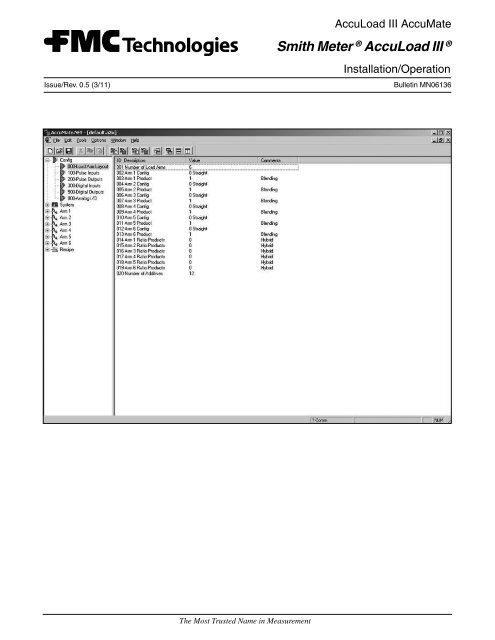
Using the Wizard to Configure New Files<br />
When the operator selects File|New|<strong>AccuLoad</strong> <strong>III</strong>.net<br />
Data File, the <strong>AccuLoad</strong> <strong>III</strong> Wizard dialog box appears,<br />
as shown in the figure below. The operator is presented<br />
with a series of lists from which he can select options<br />
for the new <strong>AccuLoad</strong> file. When an option is chosen<br />
that excludes other options, the options that are no<br />
longer available will not appear on subsequent lists. This<br />
lessens the possibility of configuration errors. The<br />
Wizard also tallies the number of digital inputs and<br />
outputs as they are assigned to specific functions,<br />
and alerts the operator when available I/O has been<br />
exceeded. To select an option, highlight it by clicking it<br />
with the mouse. Pressing "Cancel" at any time while in<br />
the Wizard creates an empty new file.<br />
Figure 7<br />
Each screen of lists includes four buttons at the<br />
bottom of the display. These buttons are "Back," "Next,"<br />
"Cancel," and "Help." Choose "Back" to return to a<br />
previous page to change a selection, "Next" to proceed<br />
to the next list of options, "Cancel" to exit the Wizard<br />
and display the new file, and "Help" to access the<br />
<strong>AccuLoad</strong> help file. For more information about each<br />
of the available options, consult the <strong>AccuLoad</strong> <strong>III</strong>.net<br />
Operator Reference Manual, Bulletin MN06129.<br />
The sequence of lists (dialog boxes) is as follows:<br />
Arm Type, Arm 1<br />
In the upper right-hand corner of the Arm Type display,<br />
as shown in Figure 8, type the address. This specifies the<br />
arm to be configured. Then, choose one of the following:<br />
• Arm Not Used<br />
• Straight Product Arm<br />
• 2-Product Sequential Blending Arm<br />
• 3-Product Sequential Blending Arm<br />
• 4-Product Sequential Blending Arm<br />
• 5-Product Sequential Blending Arm<br />
Section IV – Operations<br />
• 6-Product Sequential Blending Arm<br />
• Side-Stream Blending Arm<br />
• 2-Product Ratio Blending Arm<br />
• 3-Product Ratio Blending Arm<br />
• 4-Product Ratio Blending Arm<br />
• 5-Product Ratio Blending Arm<br />
• 6-Product Ratio Blending Arm<br />
In the box at the bottom of the display, type the number<br />
of additive injectors for the arm being configured. When<br />
the selection process is complete, press "Next."<br />
Figure 8<br />
Arm Type, Arm 2<br />
A list of Arm Type options for Arm 2 appears below.<br />
Depending on the options selected in Arm 1, not all of<br />
these will be available.<br />
• Arm Not Used<br />
• Straight Product Arm<br />
• 2-Product Sequential Blending Arm<br />
• 3-Product Sequential Blending Arm<br />
• 4-Product Sequential Blending Arm<br />
• 5-Product Sequential Blending Arm<br />
• 6-Product Sequential Blending Arm<br />
• Side-Stream Blending Arm<br />
• 2-Product Ratio Blending Arm<br />
• 3-Product Ratio Blending Arm<br />
• 4-Product Ratio Blending Arm<br />
• 5-Product Ratio Blending Arm<br />
In the box at the bottom of the display, type the number<br />
of additive injectors for the arm being configured. When<br />
the selection process is complete, press "Next."<br />
Page 10 • MN06136 Issue/Rev. 0.5 (3/11)
Arm Type, Arm 3<br />
A list of Arm Type options for Arm 3 appears below.<br />
Depending on the options selected in Arms 1 and 2, not<br />
all of these will be available.<br />
• Arm Not Used<br />
• Straight Product Arm<br />
• 2-Product Sequential Blending Arm<br />
• 3-Product Sequential Blending Arm<br />
• 4-Product Sequential Blending Arm<br />
• 5-Product Sequential Blending Arm<br />
• 6-Product Sequential Blending Arm<br />
• Side-Stream Blending Arm<br />
• 2-Product Ratio Blending Arm<br />
• 3-Product Ratio Blending Arm<br />
• 4-Product Ratio Blending Arm<br />
In the box at the bottom of the display, type the number<br />
of additive injectors for the arm being configured. When<br />
the selection process is complete, press "Next."<br />
Arm Type, Arm 4<br />
A list of Arm Type options for Arm 4 appears below.<br />
Depending on the options selected in Arms 1, 2, and 3,<br />
not all of these will be available.<br />
Figure 9<br />
Section IV – Operations<br />
• Arm Not Used<br />
• Straight Product Arm<br />
• 2-Product Sequential Blending Arm<br />
• 3-Product Sequential Blending Arm<br />
• 4-Product Sequential Blending Arm<br />
• 5-Product Sequential Blending Arm<br />
• 6-Product Sequential Blending Arm<br />
• Side-Stream Blending Arm<br />
• 2-Product Ratio Blending Arm<br />
• 3-Product Ratio Blending Arm<br />
• 4-Product Ratio Blending Arm<br />
In the box at the bottom of the display, type the number<br />
of additive injectors for the arm being configured. When<br />
the selection process is complete, press "Next."<br />
Arm Detail, Arm 1<br />
The Arm Detail display of options will be similar to that<br />
shown below in Figure 9. Note that some options are<br />
grayed-out, or unavailable, depending on selections<br />
made in previous screens. To choose an option, use<br />
the mouse to position the cursor in the box to its left,<br />
then left-click the mouse. A check mark will appear in<br />
the box to indicate that the option has been selected.<br />
When the selection process is complete, press NEXT<br />
to go to the next screen.<br />
Issue/Rev. 0.5 (3/11) MN06136 • Page 11
<strong>Meter</strong> Run, Arm 1<br />
The <strong>Meter</strong> Run display of options will be similar to that<br />
shown below in Figure 10. Note that some options are<br />
grayed-out, or unavailable, depending on selections<br />
made in previous screens. To choose an option, use<br />
the mouse to position the cursor in the circle to its left,<br />
then left-click the mouse. A dot will appear in the circle<br />
to indicate that the option has been selected. When the<br />
selection process is complete, press NEXT to advance<br />
to the next screen.<br />
Figure 10<br />
Arm Detail and <strong>Meter</strong> Run, Arms 2 through 6<br />
The two previous screens are repeated, except that<br />
this time, the operator is prompted to configure arms<br />
2 through 6 instead of arm 1. In every other respect,<br />
the displays are identical to those shown in Figures 8<br />
and 9.<br />
Additives<br />
If additives were selected, the operator will be prompted<br />
to specify an injector type from the Additives display.<br />
The available options are as follows:<br />
• Not Used<br />
• Piston<br />
• Piston with feedback<br />
• Titan<br />
• Blend-Pak<br />
• Mini-Pak<br />
• <strong>Smith</strong> Smart<br />
• <strong>Meter</strong>ed Injector<br />
• Add-Pak<br />
Section IV – Operations<br />
Choose an additive injector from the pull-down menu<br />
shown in the figure below. The Wizard will present a<br />
separate injector display for every additive specified<br />
in the setup process. When the selection process is<br />
complete, press NEXT for the next screen.<br />
Figure 11<br />
Pulse Outputs<br />
This display of options will be similar to that shown in<br />
Figure 12. Configure Pulse Outputs using the pull-down<br />
menus. For "source," select from the options below.<br />
(For ratio blending arms, also select either the total<br />
pulses or an individual meter on the arm.)<br />
• Not Used<br />
• Arm 1 Pulses<br />
• Arm 2 Pulses<br />
• Arm 3 Pulses<br />
• Arm 4 Pulses<br />
• Arm 5 Pulses<br />
• Arm 6 Pulses<br />
Choose the desired number of pulses per unit in the<br />
box labeled "pulses/unit," then select the volume type<br />
from the pull-down menu. The volume options are as<br />
follows:<br />
• IV (Raw)<br />
• GV (Gross)<br />
• GST (Gross at Standard Temperature)<br />
• GSV (Gross at Standard Temperature and<br />
Pressure)<br />
• Mass<br />
Page 12 • MN06136 Issue/Rev. 0.5 (3/11)
For more information about each of these options, refer<br />
to the <strong>AccuLoad</strong> <strong>III</strong>.net Operator Reference Manual,<br />
Bulletin MN06129. When the selection process is<br />
complete, press NEXT to advance to the next screen.<br />
Figure 12<br />
Other I/O<br />
The Other I/O display of options will be similar to<br />
that shown below in the figure below. The operator is<br />
prompted to configure shared Digital Inputs and Outputs.<br />
Select the appropriate option by placing the cursor in<br />
the box to its left and left-clicking with the mouse. A<br />
check mark will appear in the box beside a selected<br />
option. Deactivate an option by placing the cursor in a<br />
box with a check mark. Left-click with the mouse, and<br />
the check mark will disappear. Note that the AccuMate<br />
has tallied the number of digital inputs and outputs<br />
configured thus far. When the selection process is<br />
complete, press NEXT to proceed.<br />
Figure 13<br />
Section IV – Operations<br />
Confirmation<br />
This display, shown in below, summarizes the<br />
configuration choices made on all prior screens,<br />
and indicates the total number of digital inputs and<br />
outputs used. Choose "Back" to return to a prior screen<br />
to change a selection, or "Finish" to initialize and display<br />
the new <strong>AccuLoad</strong> <strong>III</strong> data file.<br />
The file will now contain programming reflecting the<br />
selections made in the wizard. Additional program codes<br />
will require modification for the <strong>AccuLoad</strong> <strong>III</strong> to perform<br />
as desired, but the Configuration directory should be<br />
nearly completed. (Some shuffling of I/O may be desired<br />
to optimize use of AC versus DC digital I/O, etc. These<br />
changes can be made after using the Wizard to do the<br />
initial setup).<br />
Figure 14<br />
Editing Program Code Data<br />
To edit program code data, first open a new or existing<br />
<strong>AccuLoad</strong> <strong>III</strong> data file. Do this by selecting "New" or<br />
"Open" from the File menu on the AccuMate tool bar.<br />
If "New" is selected, choose "<strong>AccuLoad</strong> <strong>III</strong> Data File"<br />
from the pull-down menu. If "Open" is selected, choose<br />
an existing <strong>AccuLoad</strong> <strong>III</strong> file from the pull-down menu.<br />
<strong>AccuLoad</strong> <strong>III</strong> files are designated by the file extension<br />
".A3X".<br />
A list of system groups will appear on the left of a split<br />
screen in the active <strong>AccuLoad</strong> <strong>III</strong> window. Refer to<br />
the Operator Reference Manual, Bulletin MN06129<br />
for detailed information about system groups and the<br />
program codes within each group, or click on "Help"<br />
at the far right of the AccuMate tool bar.) Clicking on<br />
"System 700 – Communications," for example, causes<br />
a listing of all program codes within the Communications<br />
group to appear on the right-hand screen, as shown in<br />
Figure 15. Double click on one of these program codes<br />
to display a dialog box.<br />
Issue/Rev. 0.5 (3/11) MN06136 • Page 13
This dialog box, "Edit Program Code Data," contains<br />
information about the selected program code. This<br />
particular dialog box provides a pull-down menu with<br />
all valid options and value ranges for the currently-<br />
selected code. When new information is selected from<br />
the pull-down menu, the new value appears on the<br />
active <strong>AccuLoad</strong> <strong>III</strong> data file screen.<br />
Figure 15<br />
Section IV – Operations<br />
To access the program code dialog box shown in<br />
Figure 16, select "Configuration," then double click on<br />
"206 Pulse Output 2 Function" in the right-hand window.<br />
The dialog box will then appear.<br />
The program code shown in Figure 16 has a pull-down<br />
pick list. To access the pick list, use the mouse to click<br />
on the down arrow at the right of the box labeled "New,"<br />
then highlight the desired option and click OK.<br />
Page 14 • MN06136 Issue/Rev. 0.5 (3/11)
If the <strong>AccuLoad</strong> <strong>III</strong> is currently online and communication<br />
with the AccuMate is active, the new value will be<br />
effective immediately; otherwise, the value change will<br />
have to be dumped to the <strong>AccuLoad</strong> when communication<br />
is established.<br />
Figure 16<br />
Other dialog boxes require the operator to type in<br />
alphanumeric data. An example of this is the box shown<br />
in Figure 17. This particular box is selected by clicking<br />
on "System," then highlighting "135 Transaction ID<br />
Message" from the menu of program codes in the<br />
window on the right. The resulting dia-log box prompts<br />
the operator to type up to twenty-eight characters (in<br />
any combination of letters and/or numbers) in the box<br />
labeled "New." Once the updated position ID information<br />
has been typed in the box, the operator clicks on OK to<br />
save the current data. The new data will appear in the<br />
"Value" column in the window on the right.<br />
The third type of dialog box allows only numeric entries.<br />
An example of this type of box is shown in Figure 18.<br />
This particular box is selected by clicking on "100 General<br />
Purpose" from the System menu, then highlighting<br />
"123 Zoom Reset Timer." The dialog box prompts the<br />
operator to enter a number from zero to 99. Once the<br />
updated information has been typed in the box, the<br />
operator clicks on OK to save the current data. All boxes<br />
of this type display help messages that include the range<br />
of the entry and other pertinent information.<br />
Section IV – Operations<br />
Figure 17<br />
Figure 18<br />
Issue/Rev. 0.5 (3/11) MN06136 • Page 15
Finally, there is the dialog box listing available options<br />
selectable with check boxes, as shown in Figure 19.<br />
To activate an option, the operator uses the mouse<br />
to position the cursor in the box to the left of the<br />
desired option, then clicks once in the box. A check mark<br />
appears to indicate that the option has been selected.<br />
To deactivate an option, position the cursor on the<br />
check and click once with the mouse. The check mark<br />
will disappear. Click on "OK" to store changes. The new<br />
selection will appear in the value column in the window<br />
on the right. Access the dialog box in Figure 19 by<br />
choosing Systems, then "600 Alarms," then "System<br />
612 Low Density Alarm."<br />
Section IV – Operations<br />
Figure 19<br />
Page 16 • MN06136 Issue/Rev. 0.5 (3/11)
Report Editor<br />
Section IV – Operations<br />
The Report Editor uses a combination of basic Windows commands (e.g., Cut, Copy, and Paste) and simple value<br />
descriptions to create customized reports. Access the Report Editor by selecting File|New|Report Configuration<br />
from the AccuMate menu bar.<br />
"Insert New Item," "Edit Selected Item," "Cut," "Copy," and "Paste" are accessed by clicking "Edit" on the AccuMate<br />
tool bar, then selecting the desired option from the pull-down menu.<br />
Insert New Item Opens a dialog box from which a new item can be added to the report.<br />
Edit Selected Item Opens a dialog box from which an existing report item, when highlighted,<br />
can be modified.<br />
Cut The item highlighted on the Report Editor will be cut from the display and stored<br />
on the clipboard.<br />
Copy The item highlighted on the Report Editor will be copied to the clipboard.<br />
Paste The information stored on the clipboard will be pasted to the Report Editor<br />
window at the specified row and column.<br />
Read Report from Uploads a report from the <strong>AccuLoad</strong>. (This option is only available when the<br />
<strong>AccuLoad</strong> <strong>III</strong> AccuMate is online.)<br />
Dump Report to Downloads a report to the <strong>AccuLoad</strong>. (This option is only available when the<br />
<strong>AccuLoad</strong> <strong>III</strong> AccuMate is online.)<br />
"Line," "Column," "Item Type," "Item Value," and "Format String" are accessed by moving the cursor to the appropriate<br />
option on the "Edit Report Item" dialog box. The "Edit Report Item" box appears whenever an existing report item<br />
on the Report screen is double-clicked.<br />
Line Indicates the row on which the data to be displayed is entered.<br />
Column Indicates the column in which the data to be displayed is entered.<br />
Item Type Selects the type of data to be entered on the screen. The choices are as follows:<br />
• User-defined text entry Displays text typed in the Item Value entry.<br />
• Database value Displays the database value for a selected register.<br />
• Database Description Displays the database descriptive text for a selected register.<br />
Item Value Displays the current value of the register; or, if a user-defined text entry is<br />
selected as Item Type, the text is entered here.<br />
Format String The format string designates the type of data to be displayed. The strings used in<br />
the <strong>AccuLoad</strong> <strong>III</strong> are based on IEEE standards and are as follows:<br />
• %uc Data labeled as "Byte" <strong>AccuLoad</strong> <strong>III</strong> (unsigned character).<br />
Issue/Rev. 0.5 (3/11) MN06136 • Page 17
Section IV – Operations<br />
• %f Data labeled as "DP Float" or "Double Precision Floating Point." Specify the<br />
length of the numeric data in this field. (The <strong>AccuLoad</strong> <strong>III</strong> stores all double precision<br />
floating point data as ten digits.) Using the number 0.2 between the "%" and the "f"<br />
right-justifies the data five places and truncates the data to two decimal places (i.e.,<br />
%0.2f). This field can be used to line up the numerical data on the screen by<br />
entering an "8" between the "%" sign and the "f" (i.e., %8f). If the requirement is to<br />
both line up the data and truncate to two decimal places, the entry would be<br />
%8.2f.<br />
• %d Data labeled as an integer in the <strong>AccuLoad</strong> <strong>III</strong> database.<br />
• %s Data labeled as a string in the <strong>AccuLoad</strong> <strong>III</strong>, consisting of multiple characters.<br />
Note 1: The "Edit Report Item" dialog box may also be opened by right-clicking on an existing report item, then<br />
selecting "Properties."<br />
Note 2: Existing report items may be moved from one location to another on the Report screen by clicking the item<br />
with the mouse, then dragging it to another position. Hold "Ctrl" while dragging to copy an entry.<br />
To create a customized report, do the following:<br />
Figure 20<br />
1. Access Report Editor by selecting File|New|Report Configuration from the AccuMate menu bar. A display<br />
similar to that shown in Figure 20 below will appear.<br />
Page 18 • MN06136 Issue/Rev. 0.5 (3/11)
Figure 21<br />
2. Next, select Edit|Insert New Item… from the<br />
AccuMate menu bar. An "Edit Report Item"<br />
dialog box will appear, similar to that shown<br />
in Figure 21.<br />
3. In the boxes labeled "Line" and "Column,"<br />
indicate the position of the new report item.<br />
In Figure 22, the text "Reprint" will appear<br />
in Line 1, Column 1 – the upper left-hand<br />
corner of the report. There are 60 lines and 80<br />
columns on a single page of an AccuMate<br />
report.<br />
4. Next, select "Item Type" from the pull-down<br />
menu shown in Figure 22. There are three<br />
options: "Run/Program Data Value," "Run/<br />
Program Data Description," and "User-defined<br />
Text." More about these options appears later<br />
in this subsection.<br />
5. To display custom information such as a<br />
company name, select "User-defined Text," type<br />
the desired information in the "Item Value" box,<br />
and click "OK." The text will appear in the<br />
appropriate position on the report screen shown<br />
in Figure 20.<br />
Section IV – Operations<br />
Figure 22<br />
6. If "Run/Program Data Value" or "Run/Program<br />
Data Description" is selected, click on "Change"<br />
beside the "Data Register" box. A menu of<br />
selections will appear. Choose an item by<br />
highlighting and double-clicking.<br />
7. Note that the format of the new entry must be<br />
appropriate for its type. A sample report<br />
appears in Figure 24. A corresponding table<br />
immediately following the figure details the item,<br />
entry type, register, format string, position, and<br />
location for each element on the report.<br />
Advanced Report Options<br />
AccuMate's Report Editor offers certain advanced<br />
configuration features that allow the operator to modify<br />
format strings, as well as the number of digits to be<br />
printed. Normally, no modification is required. AccuMate<br />
follows the "C" programming language standard for the<br />
"printf" function format string.<br />
Issue/Rev. 0.5 (3/11) MN06136 • Page 19
To access the Report Editor's advanced features,<br />
choose Edit|Insert New Item… from the AccuMate tool<br />
bar. A dialog box, similar to that shown in Figure 22,<br />
will appear. Use the mouse to click on the "Advanced"<br />
button in the lower right-hand corner of the screen to<br />
obtain the dialog box shown in Figure 23.<br />
Figure 23<br />
Use Alternate Print Format<br />
The primary benefit to the "Use Alternate Print Format"<br />
feature is the option of editing field sizes. For example,<br />
the designation %8.3f indicates a total field size of<br />
eight characters, with three numbers to the right of the<br />
decimal point. The printed report format is XXXX.XXX.<br />
(See Figure 23.) To eliminate one decimal place in this<br />
example, use the mouse to highlight the "3", then type<br />
"2". The format string for this report item is now %8.2f<br />
and the printed report format is XXXXX.XX.<br />
Reference Register<br />
This feature allows the selection of an alternate<br />
database point that may be used to either determine<br />
the offset to use for the report item, or aid in determining<br />
whether the report item should be suppressed for<br />
this printing.<br />
Use Reference Register Value as Offset for this Item<br />
If checked, the database value offset specified for this<br />
report item (the register specified on the previous dialog)<br />
will be replaced. The actual offset used to determine the<br />
value printed is the value of the reference register. The<br />
typical application for this fea-ture would be to print the<br />
correct product name. On the base dialog, the database<br />
value "Product 1 ID" may have been selected. On the<br />
report, the operator may wish to print the recipe name<br />
of the recipe delivered for this batch; however, the batch<br />
data contains only the recipe number. To print the actual<br />
recipe name, specify the Batch x Recipe number for the<br />
reference register and select this check box.<br />
Section IV – Operations<br />
Restrictions<br />
This combo box allows the selection of a test func-tion.<br />
The <strong>AccuLoad</strong> <strong>III</strong> may either print or skip this report item,<br />
depending on the result of the specified conditional. The<br />
default is to always print the entry.<br />
Always print this entry – The default option.<br />
Print if value is nonzero – Only print this entry if the<br />
value of the entry is greater than zero (database entry<br />
types only).<br />
Print if reference value is nonzero – Only print this<br />
entry if the value of the database entry specified by the<br />
reference register is zero (any entry type can use this<br />
restriction).<br />
Print if indicated batch was delivered – Only print<br />
this entry if the batch offset associated with the entry<br />
was delivered in the transaction (only valid for database<br />
entries with a "batch #" offset).<br />
Print if reference register's batch was delivered<br />
– Only print this entry if the batch offset associated<br />
with the reference register's batch was delivered in the<br />
transaction (the reference register must be a database<br />
register with a "batch #" offset).<br />
Print if this product was delivered – Only print this<br />
entry if the product offset for this entry was a product<br />
delivered in this transaction (only valid for database<br />
entries with a "product #" offset).<br />
Print if reference register's product was delivered<br />
– Only print this entry if the product offset for the reference<br />
register was a product delivered in this transaction<br />
(reference register must be a database entry with a<br />
"product #" offset).<br />
Print if this recipe was delivered – Only print this entry<br />
if the recipe offset for this entry was a recipe delivered<br />
in this transaction (only valid for database entries with<br />
a "recipe #" offset).<br />
Print if reference register's recipe was delivered<br />
– Only print this entry if the recipe offset for the<br />
reference register was a recipe delivered in this<br />
transaction (reference register must be a database entry<br />
with a "recipe #" offset).<br />
Page 20 • MN06136 Issue/Rev. 0.5 (3/11)
Sample Report<br />
Figure 24<br />
Section IV – Operations<br />
Issue/Rev. 0.5 (3/11) MN06136 • Page 21
Section IV – Operations<br />
Item Type Register Format<br />
String<br />
Row Column Where<br />
Found<br />
Reprint User-Defined Text --- %s 1 1 ---<br />
Bill of Lading User-Defined Text --- %s 3 1 ---<br />
Date Run/Program Data<br />
Description<br />
Date Run/Program Data<br />
Value<br />
Transaction Number Run/Program Data<br />
Description<br />
Transaction Number Run/Program Data<br />
Value<br />
Batch P1 Gross<br />
Volume (GV)<br />
Batch P1 Gross<br />
Volume (GV)<br />
Batch P1 Gross @<br />
Std Temp (GST)<br />
Batch P1 Gross @<br />
Std Temp (GST)<br />
Batch P1 Indicated<br />
Volume (IV)<br />
Batch P1 Indicated<br />
Volume (IV)<br />
Batch P1 Total<br />
Pulses<br />
Batch P1 Total<br />
Pulses<br />
Batch P1 Average<br />
Flow Rate<br />
Batch P1 Average<br />
Flow Rate<br />
Run/Program Data<br />
Description<br />
Run/Program Data<br />
Value<br />
Run/Program Data<br />
Description<br />
Run/Program Data<br />
Value<br />
Run/Program Data<br />
Description<br />
Run/Program Data<br />
Value<br />
Run/Program Data<br />
Description<br />
Run/Program Data<br />
Value<br />
Run/Program Data<br />
Description<br />
Run/Program Data<br />
Value<br />
Batch P1 Mass Total Run/Program Data<br />
Description<br />
Batch P1 Mass Total Run/Program Data<br />
Value<br />
Additive 1 Volume Run/Program Data<br />
Description<br />
Additive 1 Volume Run/Program Data<br />
Value<br />
Additive 2 Volume Run/Program Data<br />
Description<br />
Additive 2 Volume Run/Program Data<br />
Value<br />
101 %s 1 37 System Configuration<br />
101 %s 3 47 System Configuration<br />
--- %s 5 1 Transaction Data<br />
--- %5.0u 5 21 Transaction Data<br />
--- %s 7 1 Product Run Data for Batch<br />
--- %10.2f 7 42 Product Run Data for Batch<br />
--- %s 8 1 Product Run Data for Batch<br />
--- %10.2f 8 42 Product Run Data for Batch<br />
--- %s 9 1 Product Run Data for Batch<br />
--- %10.2f 9 42 Product Run Data for Batch<br />
--- %s 10 1 Product Run Data for Batch<br />
--- %8.1f 10 42 Product Run Data for Batch<br />
--- %s 11 1 Product Run Data for Batch<br />
--- %8.1f 11 44 Product Run Data for Batch<br />
--- %s 12 1 Product Run Data for Batch<br />
--- %10.2f 12 42 Product Run Data for Batch<br />
--- %s 14 1 Batch Data<br />
--- %8.3f 14 44 Batch Data<br />
--- %s 15 1 Batch Data<br />
--- %10.3f 15 44 Transaction Data<br />
This is to certify... User-Defined Text --- %s 19 1 N/A<br />
Described,<br />
packaged...<br />
User-Defined Text --- %s 20 1 N/A<br />
Transportation... User-Defined Text --- %s 21 1 N/A<br />
Signature Line... User-Defined Text --- %s 25 1 N/A<br />
Driver Signature User-Defined Text --- %s 26 1 N/A<br />
Signature Line User-Defined Text --- %s 30 1 N/A<br />
Signature of<br />
Receiving Agent<br />
User-Defined Text --- %s 31 1 N/A<br />
Note: The first entry on any report should be the text "Reprint." This text will only appear on reports that are reprinted; it will not appear on the<br />
first report printed.<br />
Page 22 • MN06136 Issue/Rev. 0.5 (3/11)
Translation Editor<br />
Section IV – Operations<br />
The AccuMate's Translation Editor makes it possible to replace any of the text literals in the <strong>AccuLoad</strong> <strong>III</strong> with<br />
customized text. The interface consists of a list view with the original text in the left-hand column and an edit space in the<br />
right-hand column, as shown in the figure below. The Translation Editor is accessed by selecting File|New|Translation<br />
from the AccuMate tool bar.<br />
Figure 25<br />
Issue/Rev. 0.5 (3/11) MN06136 • Page 23
A search feature allows the operator to quickly locate a<br />
specific entry by matching the text in either the original<br />
or translated literal. To use the search feature, select<br />
Edit|Find (with the Translation Editor open). A dialog<br />
box similar to that shown in the figure below will appear<br />
on the screen.<br />
Figure 26<br />
To conduct a search, type the desired text in the "Text<br />
to Find" box, specify the direction of the search, and<br />
click "Find." The specified text will be highlighted.<br />
Additional search options, "Ignore Case" and "Find From<br />
Cursor," are located on the left-hand side of the dialog<br />
box. Select these options, if desired, by using the mouse<br />
to click in the box to the left of each option. An "x" will<br />
appear in the box.<br />
Section IV – Operations<br />
To change a text literal, take the following steps:<br />
1. Double-click on the literal to be edited. A dialog<br />
box, similar to that shown in Figure 27, will appear<br />
on the screen.<br />
2. Type the new text in the space on the bottom half<br />
of the dialog box.<br />
3. Click "OK" to exit and save changes, "Cancel" to<br />
abandon the change, or "Help" for more<br />
information about this function. Assuming that<br />
new text was entered, it will appear to the right of<br />
the Translation Editor screen, as shown in Figure 28.<br />
The new literal, once downloaded to the <strong>AccuLoad</strong><br />
<strong>III</strong>, will appear in place of the original literal.<br />
Figure 27<br />
Page 24 • MN06136 Issue/Rev. 0.5 (3/11)
Figure 28<br />
Section IV – Operations<br />
Issue/Rev. 0.5 (3/11) MN06136 • Page 25
Section IV – Operations<br />
Translating Literals from English to Languages Using Non-Western Characters<br />
AccuMate supports translation of literals from English to languages using non-western characters. Available<br />
character set options are 1252-ISO-Latin 1 (the default character set), Cyrillic (866-Russian DOS and 1251-Russian<br />
Windows), East European (1250), and Greek (1253). If the PC on which the AccuMate is running is equipped with<br />
the appropriate Windows character set, translate literals by following the instructions in the immediately preceding<br />
subsection. To translate literals using 866-Russian DOS, follow the instructions given below.<br />
1. Start the AccuMate program and click on "File." From the pull-down menu, select "New" then "Translation."<br />
A display similar to that shown below will appear.<br />
Figure 29<br />
Page 26 • MN06136 Issue/Rev. 0.5 (3/11)
Section IV – Operations<br />
2. Click on the "Start" button on the PC. From the pop-up menu, select "Programs," then "Accessories."<br />
3. Click on "Character Map." A dialog box will appear, similar to that shown in the figure below.<br />
Figure 30<br />
4. Using the scroll bar at the upper left-hand corner of the dialog box, select the appropriate font. (In this<br />
example, DOS Cyrillic was chosen.) This window is now open for translating phrases in the <strong>AccuLoad</strong> <strong>III</strong>.<br />
5. Return to the AccuMate program by clicking on the AccuMate box at the bottom of the PC screen.<br />
6. On the AccuMate screen, click on "Options" on the AccuMate tool bar. From the pull-down menu, select<br />
"Options for this translation…".<br />
7. A display will appear, similar to that shown in the figure below.<br />
Figure 31<br />
Issue/Rev. 0.5 (3/11) MN06136 • Page 27
Section IV – Operations<br />
8. Return to the AccuMate screen and use the mouse to highlight the literal to be translated. The "Edit Text" box<br />
will appear.<br />
9. From the character map display, click on the first letter of the new phrase, then click on "Select." The letter<br />
will appear in the "Characters to Copy" box. Repeat this step until the entire phrase appears in the<br />
"Characters to Copy" box.<br />
10. Position the cursor to the left of the phrase, then drag the mouse across the phrase so that it is completely<br />
highlighted.<br />
11. From the keyboard, type "Ctrl" and "C" simultaneously to copy the selected text to clipboard.<br />
12. Position the cursor in the "New Text" box on the AccuMate's "Edit Text" display.<br />
13. From the keyboard, type "Ctrl" and "V" simultaneously to paste the new literal into the text box.<br />
14. Click "OK" to close the box. The new literal translation will appear on the AccuMate's translation window<br />
screen.<br />
15. To save these changes, choose "File" then "Save As…" from the AccuMate tool bar. Give the file a unique<br />
name, such as "Russian.lng".<br />
Page 28 • MN06136 Issue/Rev. 0.5 (3/11)
AccuMate Equation Editor<br />
Section V – Programmable and Boolean Statements<br />
The AccuMate makes it easy for the operator to direct the <strong>AccuLoad</strong> <strong>III</strong> to perform certain functions that are executed<br />
on a periodic basis. The AccuMate Equation Editor allows the operator to create application specific calculations, as<br />
well as to insert, delete, reorder, and edit existing equation lines. The Equation Editor is accessed by selecting File/<br />
New/Equation Set. Doing so will result in a display similar to that shown in the figure below.<br />
Figure 32<br />
Next, select Edit/Insert New to obtain the dialog box shown in Figure 33. Use the pull-down menu at the top of the<br />
display to indicate the type of equation to be set. An explanation of Boolean and algebraic expressions is included<br />
in the next subsection of this manual.<br />
Figure 33<br />
Issue/Rev. 0.5 (3/11) MN06136 • Page 29
Boolean/Algebraic Statements<br />
Section V – Programmable and Boolean Statements<br />
Boolean statements have two conditions: "true" or "false." They may also be represented as "on" or "off," or as<br />
integer values from 0 to 255. Any non-zero value is considered true; zero is false. Boolean statements can be used<br />
to create customized instructions to monitor inputs, control outputs, and calculate report values. The instructions<br />
are defined at the AccuMate, then downloaded to the <strong>AccuLoad</strong> <strong>III</strong>. The different ways of expressing Boolean statements<br />
are shown below:<br />
TEMPBOOL1 = true<br />
TEMPBOOL1 = on Equivalent Statements<br />
TEMPBOOL1 = 1<br />
TEMPBOOL2 = false<br />
TEMPBOOL2 = off Equivalent Statements<br />
TEMPBOOL2 = 0<br />
The logical operators used in conjunction with Boolean statements are "NOT", "AND", "OR", and "XOR".<br />
Refer to these definitions when studying the examples below:<br />
• TEMPBOOL1 = True<br />
• TEMPBOOL2 = True<br />
• TEMPBOOL3 = False<br />
NOT A Boolean logic operator indicating negation. A variable designated with a "NOT"<br />
in front of it will be the opposite of its current value. It is a switching function for one<br />
variable.<br />
Example: TEMPBOOL4 = NOT TEMPBOOL3 (True)<br />
AND A Boolean logic operator. If two variables are involved, both must be true for the<br />
output to be true.<br />
Example: TEMPBOOL5 = TEMPBOOL1 AND TEMPBOOL2 (True)<br />
Example: TEMPBOOL6 = TEMPBOOL1 AND TEMPBOOL3 (False)<br />
OR A Boolean logic operator. Using two variables, only one needs to be true for the<br />
output to be true.<br />
Example: TEMPBOOL7 = TEMPBOOL1 OR TEMPBOOL3 (True)<br />
XOR An exclusive or Boolean logic operator in which the output is true if either of two<br />
variables is true but not if both are true.<br />
Example: TEMPBOOL8 = TEMPBOOL1 XOR TEMPBOOL3 (True)<br />
Example: TEMPBOOL9 = TEMPBOOL1 XOR TEMPBOOL2 (False)<br />
Page 30 • MN06136 Issue/Rev. 0.5 (3/11)
Section V – Programmable and Boolean Statements<br />
Algebraic operators used in conjunction with algebraic statements are as follows:<br />
• " + " – Used to add two numerical values (2 + 2 = 4)<br />
• " - " – Used to subtract two numerical values (4 - 2 = 2)<br />
• " * " – Used to multiply two numerical values (2 * 2 = 4)<br />
• " / " – Used to divide two numerical values (1/2 = 0.5)<br />
• "ABS" – Used when the absolute value of a number is required (| -2 | = 2)<br />
• "POW" – Used to take a number to a power (2POW2 = 2 2 )<br />
Conditional operators used in conjunction with Boolean and algebraic statements are as follows:<br />
• "IF" – Used in statements where if a condition exists, then another event is to occur<br />
• " < " – Less than (1 < 2)<br />
• " > " – Greater than (2 > 1)<br />
• " = " – Greater than or equal to (2 >= 2)<br />
• " = " – Equal to (1 = 1)<br />
• " != " – Not equal to (1 ! = 5)<br />
All processing is from left to right and top to bottom:<br />
Example: 1 + 3 * 4 / 2 – 1<br />
4<br />
16<br />
8<br />
7<br />
There are 99 Boolean registers and 99 float registers. The maximum number of instruction lines per expression is<br />
200, and the maximum number of operations per statement is 4. All Boolean and algebraic equations for an <strong>AccuLoad</strong><br />
<strong>III</strong> must be stored in a single file, and all changes to equations must be made in this file.<br />
Issue/Rev. 0.5 (3/11) MN06136 • Page 31
Specific Boolean Expressions<br />
Section V – Programmable and Boolean Statements<br />
When constructing a set of equations that take<br />
action based on a level value (such as a temperature, a<br />
status value, the state of a digital I/O point, or any other<br />
value that may change between the evaluation of one<br />
equation and the next), read the value into a temporary<br />
or user-defined variable (Boolean or float, as applicable)<br />
and use the variable, not the actual value, in multiple<br />
equations.<br />
Boolean equations can be more clearly expressed as<br />
a result of an evaluated expression than by assigning<br />
a value conditionally. For example, let us as-sume that<br />
we want to turn on a digital output when the product<br />
temperature of the meter is between 70 O<br />
and 90 O<br />
, inclusive,<br />
and turn the same digital output off again when<br />
the temperature is no longer within that range. Because<br />
of the left-to-right evaluation of Boolean and algebraic<br />
expressions, it is recommended that the expressions be<br />
broken down into simple expressions so that the results<br />
are as expected.<br />
Setting a Timer<br />
Sixteen timers are available in the <strong>AccuLoad</strong> <strong>III</strong>. The<br />
breakdown is as follows:<br />
• 4 - 0.1 (Tenth) Second<br />
• 4 - 1 (One) Second<br />
• 4 - 1 (One) Minute<br />
• 4 - 1 (One) Hour<br />
A timer can be started by writing a 1 to it, and reset by<br />
writing a 0. Timers will hold values from 0 to 65535. To<br />
instruct a time to count down, set it to a negative number.<br />
For example, if Timer5 is set to –20, it will stop in<br />
20 seconds. If a continuously run-ning timer is desired,<br />
include a line in the expression that resets the timer to<br />
1 when it stops.<br />
Timer5 = 1 IF Timer5 = 0<br />
Setting an Alarm<br />
Ten user alarms are available in the <strong>AccuLoad</strong> <strong>III</strong>.<br />
These alarms are programmable, and clearable<br />
in Run or Ready mode. A text string of up to 18<br />
characters may be associated with each alarm. The<br />
set commands available are as follows:<br />
• Set Alarm Output #1<br />
• Set Alarm Output #2<br />
Inputs and Outputs<br />
The <strong>AccuLoad</strong> <strong>III</strong> can monitor any of the digital and<br />
analog inputs, and control any of the digital and analog<br />
outputs using operator-configured Boolean commands.<br />
Outputs can be configured for general purpose applications,<br />
and can be turned on or off by equations.<br />
Page 32 • MN06136 Issue/Rev. 0.5 (3/11)
Section V – Programmable and Boolean Statements<br />
The digital I/O #: (1 – 121) is the offset that are<br />
used to monitor the status of the digital I/O the numbers<br />
are associated to the relays as indicated in the tables<br />
below:<br />
1 to 43 are inputs and are numbered such in the<br />
AccuMate PC program:<br />
Input<br />
Number<br />
Description Hardware Version<br />
1-3 DC on KDC Board S, N4, Q and SA<br />
4-6 DC on EAAI Board S, N4, Q and SA<br />
7-11 AC on EAAI Board S, N4, Q and SA<br />
12-15 AC on BSE Board Q and SA<br />
16-23 DC on BSE Board Q and SA<br />
24-33 DC on AICB #1 Board S, NA, Q and SA<br />
34-43 DC on AICB #2 Board Q and SA<br />
44 to 121 are outputs and are numbered from 1 to 78<br />
in the AccuMate PC program:<br />
Output<br />
Number<br />
Description Hardware Version<br />
44-46 DC on KDC Board S, N4, Q and SA<br />
47-57 AC on EAAI Board S, N4, Q and SA<br />
58-73 AC on BSE Board Q and SA<br />
74-81 DC on BSE Board Q and SA<br />
82-101 AC on AICB #1 Board S, NA, Q and SA<br />
102-121 AC on AICB #2 Board Q and SA<br />
Example of using these I/O points in an equations<br />
that monitors a swing arm switch and two grounding<br />
systems to make sure both are aligned before loading<br />
is allowed:<br />
; Monitor Arm #1 Swing arm Switch Bay #1 (1 is a DC<br />
input on KDC board)<br />
TEMPBOOL1 = Digital I/O status 1 Current Digital I/O<br />
State = ON<br />
; Monitor Input from Ground System Bay #1 (7 is an AC<br />
input on EAAI board)<br />
TEMPBOOL2 = Digital I/O status 7 Current Digital I/O<br />
State = ON<br />
; Comparison that of the Swing Arm Switch and Ground<br />
System, both have to be true for TEMPBOOL3 to be<br />
true<br />
TEMPBOOL3 = TEMPBOOL1 AND TEMPBOOL2<br />
;Digital Output 1 is turned on if the loading arm switch<br />
and the grounding system are both aligned on Bay #1<br />
(TEMPBOOL3 is true). Digital Output #1 is wired into a<br />
permissive input allowing the <strong>AccuLoad</strong> to proceed with<br />
the transaction. (1 is a DC out-put on the KDC board)<br />
DIGOUT1 = TEMPBOOL3<br />
Variables and Registers<br />
Temporary variables include the following:<br />
• TEMPBOOL1 to TEMPBOOL99<br />
• TEMPFLOAT1 to TEMPFLOAT99<br />
• Place holders used by other instruction lines.<br />
User memory consists of the following:<br />
• USERBOOL1 to USERBOOL99<br />
• USERFLOAT1 to USERFLOAT99.<br />
All variables and registers can be read and written to<br />
by equations. They can also be accessed via AccuMate<br />
communications and their values included in user-<br />
configured reports.<br />
Possible Boolean Applications<br />
In addition to the applications listed above, several other<br />
operations can be initiated or controlled using Boolean<br />
equations. These include the following:<br />
• Periodic maintenance notification<br />
• Relay output at first trip point<br />
• Viscometer input set points<br />
• Detection of density change<br />
• Temperature calculations (C, F or K)<br />
• Indicator lights<br />
• Close safety valve on an overrun alarm.<br />
Example A: Closing a relay (and safety valve<br />
downstream of a digital control valve) in the event of an<br />
overrun alarm<br />
DIGOUT4 = Load Arms OA: System Overrun Alarm<br />
Issue/Rev. 0.5 (3/11) MN06136 • Page 33
Section V – Programmable and Boolean Statements<br />
Take the following steps to initiate this action:<br />
1. With the AccuMate program open, go to File/New<br />
Equation Set.<br />
2. Click on Edit/Insert New<br />
3. From the "Edit Equation Line" screen, top box,<br />
select the output to be configured for this<br />
function. (Note: the output must be configured<br />
for general purpose use in the configuration.) For<br />
this example, we will use output #4.<br />
4. Move the cursor to the box directly below and<br />
delete the 0.<br />
5. Move the mouse to the button for @register<br />
and click.<br />
6. From the "Select Data Item" screen, select the<br />
Load Arm Alarms by clicking on it.<br />
7. Move the cursor down to OA: System Overrun<br />
Alarm.<br />
8. Click on the OK button.<br />
9. The AccuMate will display @152699392 (register<br />
number) in the second box. Directly below the<br />
register number will be displayed "OUTPUT4 =<br />
Load Arm Alarms OA, System Overrun<br />
Alarm."<br />
10. Click on OK. The register and alarm information<br />
will be transferred to the scratch pad.<br />
11. The equation can now be downloaded to the<br />
<strong>AccuLoad</strong> <strong>III</strong> by clicking on the "Dump Selected<br />
Item" button.<br />
12. The equation can be saved as a file for future<br />
use by going to "File/Save As" and assigning a<br />
file name to the data. Equation files have a .eq<br />
extension.<br />
Example B: Closing a relay (and safety valve downstream<br />
of a digital control valve), unless intervention<br />
has occurred either through the keypad or through<br />
communications.<br />
TEMPBOOL1 = Load Arm ALarms OA: System<br />
Overrun Alarm; check USERBOOL1 if not 0 ignore<br />
alarm, keep valve open<br />
TEMPBOOL2 = TEMPBOOL1 AND NOT USER-BOOL1;<br />
check USERBOOL2 if not 0 close valve always<br />
DIGOUT 4 = TEMPBOOL2 or USERBOOL2<br />
Take the following steps to initiate this action:<br />
1. With AccuMate program open, go to File/New/<br />
Equation set.<br />
2. Click on Edit/Insert New.<br />
3. From the Edit Equation Line screen, top box,<br />
select the temporary Boolean storage.<br />
4. The box to the right will indicate this is register1.<br />
5. Move the cursor to the box directly below and<br />
delete the 0.<br />
6. Move the mouse to button for @register and<br />
click.<br />
7. From the Select Data Item screen, select<br />
Load Arm Alarms by clicking the left<br />
hand button on the mouse.<br />
8. Move the cursor down to OA: System Overrun<br />
Alarm.<br />
9. Click on the OK button.<br />
10. The AccuMate will display @152699392<br />
(register number) in the second box. Below that<br />
box will be displayed “TEMPBOOL1 = Load Arm<br />
Alarms OA, System Overrun Alarm.”<br />
11. Click on OK to transfer the data to the scratch<br />
pad.<br />
12. Click on Edit/Insert New to start next item.<br />
13. The next line is a comment line for a reminder<br />
of what the next statement will do. From the Edit<br />
Equation Line screen, top box, select “comment<br />
only” for this line.<br />
14. Move the cursor to the box directly below and<br />
delete the 0.<br />
15. Type in the comment “check USERBOOL1 if not<br />
0 ignore alarm, keep valve open.”<br />
16. Click on OK to transfer the comment to the<br />
scratch pad. (Note: Comments are not<br />
downloaded to the <strong>AccuLoad</strong> <strong>III</strong>; therefore, if<br />
equations are uploaded from an <strong>AccuLoad</strong>, the<br />
comment lines will not appear.)<br />
17. Click on Edit/Insert New Item to start the next<br />
item.<br />
18. From the Edit Equation Line screen, top box,<br />
select Temporary Boolean Storage.<br />
19. Move the cursor to the box at the right and<br />
change the number from 1 to 2.<br />
20. Move the cursor to the box directly below and<br />
delete the 0.<br />
21. Enter "TEMPBOOL1 AND NOT USERBOOL1"<br />
(AND and NOT can either be typed or selected<br />
from the buttons below).<br />
22. Click on OK to transfer the statement to the<br />
scratch pad.<br />
23. Click on Edit/Insert New to start a new item.<br />
24. The next line is a comment line for a reminder of<br />
what the next statement will do. From the Edit<br />
Equation Line screen, top box, select "Comment<br />
Only" for this line.<br />
25. Move the cursor to the box directly below and<br />
delete the 0.<br />
26. Type in the comment "Check USERBOOL2 if not<br />
0 close valve always".<br />
Page 34 • MN06136 Issue/Rev. 0.5 (3/11)
Section V – Programmable and Boolean Statements<br />
27. Click on OK to transfer the statement to the<br />
scratch pad.<br />
28. Click on Edit/Insert New Item to start the next<br />
item.<br />
29. From the Edit Equation Line screen, top box,<br />
select "DIGITAL OUTPUT #4."<br />
30. Move the cursor to the box directly below and<br />
delete the 0.<br />
31. Enter "TEMPBOOL2 OR USERBOOL2" (OR can<br />
either be typed or selected from the buttons<br />
below).<br />
32. Click on OK to transfer the statement to the<br />
scratch pad.<br />
33. The expression is now complete. The file can be<br />
saved or downloaded to the <strong>AccuLoad</strong> and/or<br />
another expression can be added to the file.<br />
Example C: Turn on digital output #1 when the product<br />
temperature is between 175 o and 250 o .<br />
TEMPBOOL1 = Arm Product Run Data(1)<br />
Current Product Temperature<br />
>= 175<br />
TEMPBOOL2 = Arm Product Run Data(1)<br />
Current Product Temperature<br />
=175<br />
TEMPBOOL2 = Transaction Data Current Temperature<br />
Algebraic Expressions<br />
Section V – Programmable and Boolean Statements<br />
The <strong>AccuLoad</strong> <strong>III</strong> converts all algebraic values to double precision floating point values prior to performing<br />
calculations.<br />
Calculations may be defined using positive or negative whole numbers, fractional numbers, or a combination.<br />
Algebraic expressions are evaluated from left to right and all operators (+, -, /, *) have the same precedence.<br />
Multiplication does not take place before addition, etc. The following expression has a result of 54.<br />
TEMPFLOAT1 = 4 + 5 * 6 (Result 54, 4 + 5 = 9 * 6 = 54)<br />
Algebraic processing will allow out of range values, such as division by zero, or evaluations of expressions whose<br />
results are greater than the range of a double precision floating point variable. It is the responsibility of the user to<br />
ensure that valid expressions are used.<br />
Page 36 • MN06136 Issue/Rev. 0.5 (3/11)
Section V – Programmable and Boolean Statements<br />
Coefficient of Thermal Expansion Calculator<br />
The Coefficient of Thermal Expansion Calculator is used to determine the Coefficient of Thermal Expansion for<br />
nonstandard products that are not listed in API reference tables. This tool provides an accurate coefficient value,<br />
which the <strong>AccuLoad</strong> will use to calculate the CTL value.<br />
Issue/Rev. 0.5 (3/11) MN06136 • Page 37
Section V – Programmable and Boolean Statements<br />
This calculator uses input sample data which consists of temperature and density values. There are several<br />
guidelines for entering sample data. These guidelines are listed below:<br />
• The calculator will not allow more than 20 samples to be entered and will not calculate the coefficient if less<br />
than 2 samples entered.<br />
• One sample temperature must be above 60°F and one sample temperature must be below 60°F in order for<br />
the coefficient to be calculated.<br />
• Temperatures may not exceed the range: {-999.9 to 999.9}<br />
• Densities in kg/m3 or lb/ft3 may not exceed the range: {0.0 to 9999.9}<br />
• Densities in API may not exceed the range: {-999.9 to 999.9}<br />
• Densities in Relative Density (Rel. D) may not exceed the range: {0.0 to 9.9}<br />
For accuracy purposes, API recommends entering at least10 samples and all of the data should be as precise as<br />
possible. For instance, 888.8889 kg/m3 should be entered just as shown; do not round this value and enter it as<br />
888.89 kg/m3. If the chosen units are different than Fahrenheit and Kg/m3, the accuracy of the resulting coefficient<br />
will NOT be sacrificed.<br />
Removing data from the list of entered data can be easily done. To select undesired data from the list of data, click<br />
on the data that should be deleted. Then click the Remove Selected button and the selected data will be removed.<br />
If all of the data is undesired, then no data needs to be selected; just simply click the Remove All button.<br />
Page 38 • MN06136 Issue/Rev. 0.5 (3/11)
Section V – Programmable and Boolean Statements<br />
If metric units are desired, click the metric units check box located below the result text box. The units in the result<br />
will change and the result will undergo a conversion procedure.<br />
1. Prepare an AccuMate file. API Table (ID number 411) must be set to “6C”. This table defines a non standard<br />
product.<br />
2. Now enter the coefficient value as the reference density (ID number 412).<br />
3. If temperature input is available, make sure that the maintenance temperature (ID 401) is set to-999.9. Otherwise, if a<br />
temperature input is not available, then enter a temperature here.<br />
4. Set these parameters all the same for the remaining products. In this case, Products 2, 3, and 4 would all<br />
use a 6C API table along with the calculated reference density.<br />
5. When finished dump the AccuMate file to the <strong>AccuLoad</strong>. Now the coefficient of thermal expansion as been<br />
set and an accurate CTL value will be calculated during the next batch.<br />
6. Now run a batch.<br />
Issue/Rev. 0.5 (3/11) MN06136 • Page 39
The specifications contained herein are subject to change without notice and any user of said specifications should verify from the manufacturer that the specifications are currently<br />
in effect. Otherwise, the manufacturer assumes no responsibility for the use of specifications which may have been changed and are no longer in effect.<br />
Contact information is subject to change. For the most current contact information, visit our website at www.fmctechnologies.com/measurementsolutions and click on the<br />
“Contact Us” link in the left-hand column.<br />
Headquarters:<br />
500 North Sam Houston Parkway West, Suite 100, Houston, TX 77067 USA, Phone: +1 (281) 260 2190, Fax: +1 (281) 260 2191<br />
<strong>Measurement</strong> Products and Equipment:<br />
Erie, PA USA +1 (814) 898 5000<br />
Ellerbek, Germany +49 (4101) 3040<br />
Barcelona, Spain +34 (93) 201 0989<br />
Beijing, China +86 (10) 6500 2251<br />
Buenos Aires, Argentina +54 (11) 4312 4736<br />
Burnham, England +44 (1628) 603205<br />
Section VI – Related Publications<br />
The following literature can be obtained from FMC Technologies <strong>Measurement</strong> <strong>Solutions</strong> Literature Fulfillment at<br />
johno@gohrs.com or online at www.fmctechnologies.com/measurementsolutions. When requesting literature from<br />
Literature Fulfillment, please reference the appropriate bulletin number and title.<br />
AccuMate for <strong>AccuLoad</strong> <strong>III</strong><br />
Specification .................................................................................................................................... Bulletin SS06032<br />
AccuMate for <strong>AccuLoad</strong> <strong>III</strong>-X Installation/Operation ....................................................................... Bulletin MN06136<br />
<strong>AccuLoad</strong> <strong>III</strong>-X<br />
Specification .................................................................................................................................... Bulletin SS06036<br />
Installation/Operation ...................................................................................................................... Bulletin MN06135<br />
Operator Reference ........................................................................................................................ Bulletin MN06129<br />
Installation/Operation .................................................................................................................... Bulletin MN06130L<br />
Modbus Communications ............................................................................................................. Bulletin MN06131L<br />
Revisions included in MN06136 Issue/Rev. 0.5 (3/11)<br />
Page 33: Edited Possible Boolean Applications: Example A<br />
Page 34: Edited Possible Boolean Applications: Example B<br />
Page 35: Edited Possible Boolean Applications: Examples C & D<br />
Dubai, United Arab Emirates +971 (4) 883 0303<br />
Los Angeles, CA USA +1 (310) 328 1236<br />
Melbourne, Australia +61 (3) 9807 2818<br />
Moscow, Russia +7 (495) 5648705<br />
Singapore, +65 6861 3011<br />
Thetford, England +44 (1842) 822900<br />
Visit our website at www.fmctechnologies.com/measurementsolutions<br />
Printed in U.S.A. © 3/11 FMC Technologies <strong>Measurement</strong> <strong>Solutions</strong>, Inc. All rights reserved. MN06136 Issue/Rev. 0.5 (3/11)<br />
Integrated <strong>Measurement</strong> Systems:<br />
Corpus Christi, TX USA +1 (361) 289 3400<br />
Kongsberg, Norway +47 (32) 286700<br />
Dubai, United Arab Emirates +971 (4) 883 0303


