INSTRUCTION MANUAL - rumia.edu.pl
INSTRUCTION MANUAL - rumia.edu.pl
INSTRUCTION MANUAL - rumia.edu.pl

You also want an ePaper? Increase the reach of your titles
YUMPU automatically turns print PDFs into web optimized ePapers that Google loves.
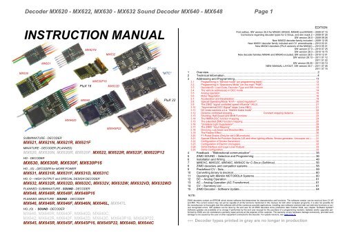
Decoder MX620 - MX622, MX630 - MX632 Sound Decoder MX640 - MX648 Page 1<br />
<strong>INSTRUCTION</strong> <strong>MANUAL</strong><br />
MX621<br />
MX621N<br />
MX632<br />
21-pin<br />
MX630 “MTC“<br />
MX642D<br />
SUBMINIATURE - DECODER<br />
MX621, MX621N, MX621R, MX621F<br />
MX630P16<br />
PluX 16 MX632D<br />
MX642 PluX 22<br />
MX643P22<br />
MINIATURE - DECODER (PLANNED)<br />
MX620, MX620N, MX620R, MX620F, MX622, MX622R, MX622F, MX622P12<br />
HO - DECODER<br />
MX630, MX630R, MX630F, MX630P16<br />
HO , (O) - DECODER for MORE POWER<br />
MX631, MX631R, MX631F, MX631D, MX631C<br />
HO, O – HIGH OUTPUT and SPECIAL DESIGN DECODER<br />
MX632, MX632R, MX632D, MX632C, MX632V, MX632W, MX632VD, MX632WD<br />
PLANNED: SUBMINIATURE - SOUND - DECODER<br />
MX648, MX648R, MX648F, MX648P16<br />
PLANNED: MINIATURE - SOUND – DECODER<br />
MX646, MX646R, MX646F, MX646N, MX646L, MX647L<br />
HO, (O) - SOUND - DECODER<br />
MX640, MX640R, MX640F, MX640D, MX640C,<br />
MX642, MX642R, MX642F, MX642D, MX642C, MX643P16, MX643P22,<br />
MX645, MX645R, MX645F, MX645P16, MX645P22, MX644D, MX644C<br />
1<br />
First edition. SW version 25.0 for MX620, MX630, MX64D and MX640 – 2009 07 15<br />
Corrections regarding decoder types for C-Sinus, and dim mask 2 -- 2009 07 25<br />
SW version 26.0 – 2009 09 26<br />
New MX632 decoder family included -- 2009 12 05<br />
New MX631 decoder family included and CV amendments -- 2010 03 01<br />
New MX643 decoders (PluX versions of the MX642) -- 2010 05 01<br />
SW version 27.0 – 2010 07 25<br />
SW version 28.3 – 2010 10 15<br />
New decoder families MX646 and MX645 included, SW version 28.5 – 2010 12 01<br />
SW version 28.13 – 2011 01 12<br />
2011 01 22<br />
SW version 28.25 – 2011 03 10<br />
NEW <strong>MANUAL</strong> LAYOUT, SW version 30.7 – 2011 07 05<br />
2011 07 15<br />
Overview.......................................................................................................................................... 2<br />
2 Technical Information ...................................................................................................................... 4<br />
3 Addressing and Programming....................................................................................................... 11<br />
3.1 Programming in “Service mode” (on programming track) .............................................................................. 12<br />
3.2 Programming in “Operations Mode” (on-the-main “PoM”) ............................................................................. 13<br />
3.3 Decoder-ID, Load-Code, Decoder-Type and SW-Version ............................................................................. 13<br />
3.4 The vehicle address(es) in DCC mode .......................................................................................................... 14<br />
3.5 Analog operation............................................................................................................................................ 15<br />
3.6 Motor Regulation ........................................................................................................................................... 16<br />
3.7 Acceleration and Deceleration: ...................................................................................................................... 19<br />
3.8 Special Operating Mode “km/h – speed regulation“ ...................................................................................... 20<br />
3.9 The ZIMO “signal controlled speed influence” (HLU) ..................................................................................... 21<br />
3.10 “Asymmetrical DCC-Signal” stops (Lenz ABC) .............................................................................................. 21<br />
3.11 DC brake sections a.k.a. “Märklin brake mode” ............................................................................................. 22<br />
3.12 Distance controlled stopping – Constant stopping distance ................................. 22<br />
3.13 Shunting, Half-Speed and MAN Functions: ................................................................................................... 23<br />
3.14 The NMRA-DCC function mapping ................................................................................................................ 24<br />
3.15 The extended ZIMO function mapping........................................................................................................... 25<br />
3.16 “Unilateral Light Suppression”........................................................................................................................ 29<br />
3.17 The ZIMO “Input Mapping” ............................................................................................................................ 29<br />
3.18 Dimming, Low beam and Direction Bits ......................................................................................................... 29<br />
3.19 The Flasher Effect ......................................................................................................................................... 30<br />
3.20 F1-Pulse Chains (Only for old LGB products) ................................................................................................ 31<br />
3.21 Special Effects for Function Outputs (US and other lighting effects, Smoke generator, Uncou<strong>pl</strong>er etc.) ....... 31<br />
3.22 Configuration of Smoke Generators .............................................................................................................. 32<br />
3.23 Configuration of Electric Uncou<strong>pl</strong>ers.............................................................................................................. 33<br />
3.24 SUSI-Interface and Logic-Level Outputs ....................................................................................................... 33<br />
3.25 Servo Configuration ....................................................................................................................................... 33<br />
4 Feedback - “Bidirectional communication” ................................................................................... 35<br />
5 ZIMO SOUND – Selection and Programming .............................................................................. 36<br />
6 Installation and Wiring ................................................................................................................... 48<br />
7 MX631C, MX632C, MX640C, MX642C for C-Sinus (Softdrive).................................................... 56<br />
8 ZIMO decoders and competitor systems ...................................................................................... 58<br />
9 Predefined CV - Sets..................................................................................................................... 59<br />
10 Converting binary to decimal......................................................................................................... 60<br />
11 Operating with Märklin MOTOROLA Systems .............................................................................. 60<br />
12 DC – Analog Operation ................................................................................................................. 61<br />
13 AC – Analog Operation (AC-Transformer) .................................................................................... 61<br />
14 CV – Summery List ....................................................................................................................... 61<br />
15 ZIMO Decoder - Software Update................................................................................................. 64<br />
NOTE:<br />
ZIMO decoders contain an EPROM which stores software that determines its characteristics and functions. The software version can be read out form CV #7<br />
and #65. The current version may not yet be capable of all the functions mentioned in this manual. As with other computer programs, it is also not possible for<br />
the manufacturer to thoroughly test this software with all the numerous possible ap<strong>pl</strong>ications. Installing new software versions later can add new functions or correct<br />
recognized errors. SW updates can be done by the end user for all ZIMO decoders since production date October 2004, see chapter “Software Update”!<br />
Software updates are available at no charge if performed by the end user (except for the purchase of a programming module); Updates and/or upgrades performed<br />
by ZIMO are not considered a warranty repair and are at the expense of the customer. The warranty covers hardware damage exclusively, provided such<br />
damage is not caused by the user or other equipment connected to the decoder. For update versions, see www.zimo.at.<br />
Page 2 Decoder MX620 - MX622, MX630 - MX632 Sound Decoder MX640 - MX648<br />
1 Overview<br />
These decoders are suitable for N, HOe, HOm, TT, HO, OO, Om and O gauge engines with standard<br />
or coreless motors (Faulhaber, Maxxon etc.)<br />
They operate primarily in the NMRA-DCC data format with any NMRA-DCC compatible system, as<br />
well as the MOTOROLA protocol within Märklin systems and other MOTOROLA command stations.<br />
Zimo decoders also operate in DC analog mode with DC power packs (including PWM). Beginning<br />
with the July 2010 software version, ZIMO decoders also operate with AC analog (Märklin<br />
Transformers with over-voltage pulses for direction change).<br />
MX620<br />
Family<br />
Production stopped in June of 2010; re<strong>pl</strong>aced by MX621.<br />
12 x 6.5 x 2 mm No-Sound - 0.7 A DCC and DC-Analog (not for MOTOROLA)<br />
MX621<br />
Family<br />
MX621 <strong>pl</strong>ug configurations:<br />
MX621<br />
MX621N<br />
The MX621 re<strong>pl</strong>aces the MX620 since December 2010.<br />
Sub-miniature Decoder, with r<strong>edu</strong>ced ZIMO features; missing in the software<br />
are: MM (Motorola), Servos, SUSI, ZIMO special function mapping.<br />
TYPCIAL APPLICATION: Vehicles in N, HOe and HOm.<br />
7 wires (120mm long) for power pick-up, motor and 2 function outputs. Two<br />
more function outputs on solder pads.<br />
MX621 with 6-pin <strong>pl</strong>ug as per NEM651 and NMRA RP9.1.1, mounted on the<br />
circuit board.<br />
MX621R MX621 with 8-pin <strong>pl</strong>ug as per NEM652 on 70mm wires.<br />
MX621F MX621 with 6-pin <strong>pl</strong>ug as per NEM651 on 70mm wires.<br />
14 x 9 x 2.5 mm (<strong>pl</strong>anned) No-Sound - 0.8A - 6 Fu-Outputs - 2 Servos - SUSI<br />
Planned<br />
MX622<br />
Family<br />
MX622 <strong>pl</strong>ug configurations:<br />
The MX622 will re<strong>pl</strong>ace the MX620 on June 2011.<br />
Miniature-Decoder, with all ZIMO features.<br />
TYPCIAL APPLICATION: Vehicles in N, HOe, HOm and in HO vehicles with<br />
limited space.<br />
MX622 7 wires (120mm long) for power pick-up, motor and 2 function outputs. Two more<br />
function outputs on solder pads.<br />
MX622R MX622 with 8-pin <strong>pl</strong>ug as per NEM652 on 70mm wires.<br />
MX622F MX622 with 6-pin <strong>pl</strong>ug as per NEM651 on 70mm wires.<br />
MX622P12 MX622 with 12-pin PluX connector, mounted on circuit board.<br />
20 x 11 x 3.5mm No-Sound - 1.0A - 6 Fu-Outputs - 2 Servos - SUSI<br />
MX630<br />
Family<br />
MX630 <strong>pl</strong>ug configurations:<br />
Compact HO loco decoder, for universal ap<strong>pl</strong>ications.<br />
TYPICAL APPLICATION: Locomotives in HO, O or similar scale where space is<br />
limited. Due to excellent dielectric strength (50V), the decoder is also suitable for<br />
AC analog operation with the old Märklin transformers.<br />
MX630 9 highly flexible wires (120mm) for pick-up, motor and 4 function outputs. Solder<br />
pads for 2 additional function outputs, logic level outputs or Servo outputs as well<br />
as SUSI.<br />
MX630R MX630 with 8-pin <strong>pl</strong>ug as per NEM652 on 70mm wires.<br />
MX630F MX630 with 6-pin <strong>pl</strong>ug as per NEM651 on 70mm wires.<br />
MX630P MX630 with 16-pin PluX connector, mounted on circuit board.<br />
20.5 x 15.5 x 4mm No-Sound - 1.2 A - 6 Fu-Outputs - 2 Servos - SUSI<br />
MX631<br />
Family<br />
MX631 <strong>pl</strong>ug configurations:<br />
H0-Decoder, similar to MX630 but with more performance and energy storage<br />
circuitry on board.<br />
TYPICAL APPLICATION: HO and smaller O vehicles. Due to excellent dielectric<br />
strength (50V), the decoder is also suitable for AC analog operation with the old<br />
Märklin transformers.<br />
MX631 11 highly flexible wires (120mm) for pick-up, motor and 4 function outputs. Solder<br />
pads for 2 additional function outputs, logic level outputs or Servo outputs as well as<br />
SUSI.<br />
MX631R MX631 with 8-pin <strong>pl</strong>ug as per NEM652 on 70mm wires.<br />
MX631F MX631 with 6-pin <strong>pl</strong>ug as per NEM651 on 70mm wires.<br />
MX631D MX631 with 21-pin „MTC“ <strong>pl</strong>ug mounted on decoder board.<br />
MX631C Similar to MX631D but for Märklin-, Trix- and similar vehicles; which require FA3,<br />
FA4 as logic level outputs for motor control.<br />
28 x 15.5 x 4mm No-Sound - 1.6A - 8 Fu-Outputs - 2 Servos - SUSI<br />
MX632<br />
Family<br />
High output decoder, with built-in energy storage circuitry.<br />
TYPICAL APPLICATON: HO, O and similar gauge, especially for vehicles with<br />
low voltage bulbs (1.5 or 5V).
Decoder MX620 - MX622, MX630 - MX632 Sound Decoder MX640 - MX648 Page 3<br />
Special versions and <strong>pl</strong>ug configurations of the MX632:<br />
MX632<br />
11 highly flexible wires (120mm) for pick-up, motor and 4 function outputs. Solder<br />
pads for 4 additional function outputs, logic level outputs, Servo outputs as<br />
well as SUSI.<br />
MX632R MX632 with 8-pin <strong>pl</strong>ug as per NEM652 on 70mm wires.<br />
MX632D MX632 with 21-pin „MTC“ <strong>pl</strong>ug mounted on decoder board.<br />
MX632C Similar to MX631D but for Märklin-, Trix- and similar vehicles; which require<br />
FA3, FA4 as logic level outputs for motor control.<br />
MX632V, VD<br />
MX632W, WD<br />
Decoders with low voltage sup<strong>pl</strong>y for function outputs:<br />
...V = 1.5V, ...W = 5V, ...VD or ...WD = with 21-pin <strong>pl</strong>ug.<br />
20 x 11 x 4mm SOUND - 0.8A - 4 Fu-Outputs - 2 Servos - SUSI<br />
Planned<br />
MX648<br />
Family<br />
MX648 <strong>pl</strong>ug configurations:<br />
Subminiature-Sound-Decoder, 1 Watt Audio on 8 Ohm speaker<br />
TYPICAL APPLICATION: Vehicles in N, TT, HOe, HOm and in HO vehicles with<br />
limited space.<br />
MX648 9 highly flexible wires for pick-up, motor, 2 Fu-Outputs, speaker, solder pads for 2<br />
more Fu-Outputs, logic level outputs, servos and SUSI.<br />
MX648R MX648 with 8-pin <strong>pl</strong>ug as per NEM652 on 70mm wires.<br />
MX648F MX648 with 6-pin <strong>pl</strong>ug as per NEM651 on 70mm wires.<br />
MX648P16 MX648 with 16-pin PluX connector (male), mounted on circuit board.<br />
28 x 10.5 x 4mm SOUND - 1.0A - 4 Fu-Outputs - 2 Servos - SUSI<br />
MX646<br />
Family<br />
Miniature-Sound-Decoder, 1 Watt Audio on 8 Ohm speaker<br />
TYPICAL APPLICATION: Vehicles in N, TT, HOe, HOm and in HO vehicles with<br />
limited space.<br />
MX646 <strong>pl</strong>ug configurations (also for the interim type MX647):<br />
MX646<br />
9 highly flexible wires for pick-up, motor, 2 Fu-Outputs, speaker, solder pads for<br />
2 more Fu-Outputs, logic level outputs, servos and SUSI.<br />
MX646N MX646 with 6-pin <strong>pl</strong>ug as per NEM651 mounted on circuit board and two additional<br />
speaker wires.<br />
MX646L MX646 with 90 o 6-pin <strong>pl</strong>ug as per NEM651 mounted on circuit board and two<br />
additional speaker wires.<br />
MX646R MX646 with 8-pin <strong>pl</strong>ug as per NEM652 on 70mm wires.<br />
MX646F MX646 with 6-pin <strong>pl</strong>ug as per NEM651 on 70mm wires.<br />
MX647L Produced only until Oct. 2010, before the MX646W became available.<br />
MX640<br />
Family<br />
Production stopped end of 2010; re<strong>pl</strong>aced by MX642 and MX644.<br />
MX642<br />
Family<br />
MX643<br />
Family<br />
Production stopped end of 2010; re<strong>pl</strong>aced by MX644 and MX645.<br />
Production stopped end of 2010; re<strong>pl</strong>aced by MX645.<br />
30 x 15 x 4mm SOUND - 1.2A - 10 Fu-Outputs - 2 Servos - SUSI<br />
MX645<br />
Family<br />
MX645 <strong>pl</strong>ug configurations:<br />
MX645 re<strong>pl</strong>aces MX642 (except ..D and ..C) and MX643 since January 2011.<br />
H0-Sound-Decoder, 3 Watt Audio on 4 Ohm speaker (or 2 x 8 Ohm), with<br />
energy storage circuitry.<br />
TYPICAL APPLICATION: HO, O and similar gauges.<br />
MX645 13 highly flexible wires (120mm) for pick-up, motor, 4 Fu-Outputs, speaker, energy<br />
storage circuitry, solder pads for additional 4 Fu-Outputs, logic level outputs,<br />
servos and SUSI.<br />
MX645R<br />
MX645 with 8-pin <strong>pl</strong>ug as per NEM652 on 70mm wires.<br />
MX645F MX645 with 6-pin <strong>pl</strong>ug as per NEM651 on 70mm wires.<br />
MX645P16 MX645 with 16-pin PluX connector, 4 Fu-Outputs.<br />
MX645P22 MX645 with 22-pin PluX connector, 9 Fu-Outputs (+ extra output).<br />
30 x 15 x 4mm SOUND - 1.2A - 6 Fu-Outputs - 2 Servos - SUSI<br />
MX644<br />
Family<br />
MX644 <strong>pl</strong>ug configurations:<br />
(MX644) .<br />
MX644 re<strong>pl</strong>aces MX640D, ..C and MX642D, ..C since March 2011.<br />
H0-Sound-Decoder, 3 Watt Audio on 4 Ohm speaker (or 2 x 8 Ohm), with<br />
energy storage circuitry.<br />
TYPICAL APPLICATION: HO, O and similar gauges with 21-pin „MTC“ interface.<br />
13 highly flexible wires (120mm) for pick-up, motor, 4 Fu-Outputs, speaker, energy<br />
storage circuitry, solder pads for additional 4 Fu-Outputs, logic level outputs, servos<br />
and SUSI.<br />
MX644D MX644 with 21-pin „MTC“ <strong>pl</strong>ug mounted on circuit board.<br />
MX644C MX644 as above but for Märklin-, Trix and similar; FA3, FA4 logic level only.
Page 4 Decoder MX620 - MX622, MX630 - MX632 Sound Decoder MX640 - MX648<br />
2 Technical Information<br />
Allowable Track voltage **) ............................................................................................minimum 10 V<br />
MX620, MX640 (discontinued) .......................................................... max. 24 V<br />
MX621, MX622, MX646, MX647, MX648 ......................................... max. 35 V<br />
MX630, MX631, MX632, MX644, MX645, … Digital or DC analog…. max. 35 V<br />
MX630, MX631, MX632, MX642 operated with AC analog pulse…... max. 50V<br />
Maximum continuous motor current. MX620, MX621, MX622, MX648 ...................................... 0.8 A<br />
MX630, MX646 .... ............................................................ 1.0 A<br />
MX631, MX640, MX642, MX643, MX644, MX645 … ..... 1.2 A<br />
MX632 ............................................................................... 1.6 A<br />
Peak motor current…………………..MX620, MX621, MX646, MX648 ...……………………….1.5 A<br />
MX630 - MX632, MX640 - MX645 for @ 20 sec…….….2.5 A<br />
Maximum total function output, continuous *)………. MX620, MX621. MX646 ........................ 0.5 A<br />
MX630 - MX632, MX640 - MX645 .................................... 0.8 A<br />
Maximum continuous current for LED outputs ....…MX640, MX642, MX644……………... 10 mA ea<br />
Maximum continuous total current (motor and functions)…… = maximum continuous motor current<br />
Operating temperature ................................................................................................. - 20 to 100 o C<br />
MX640 - MX648: Memory size for sound sam<strong>pl</strong>es…………………….. 32 Mbit (= 180 sec. at 22 kHz)<br />
MX640 - MX648: Sam<strong>pl</strong>e rate……depending on sound sam<strong>pl</strong>e………………………..…11 or 22 kHz<br />
MX640 - MX648: Number of independent sound channels …………………………………………… 4<br />
MX640 - MX648: Sound am<strong>pl</strong>ifier output (Sinus)…. (MX640, MX646, MX648) 1.1W, (others) 3 W<br />
MX640: Loud speaker impedance…………...(MX640, MX646, MX648) 8 Ohm, (others) from 3 Ohm<br />
Operating temperature … ...................................................................................... …. - 20 to 100 o C<br />
Dimensions (L x W x H) … ............ MX620, MX620N (excluding pins) …. ............. 14 x 9 x 2.5 mm<br />
MX621, MX621N (excluding pins)...……..….12 x 8.5 x 2.0 mm<br />
MX622, MX622P16 (excluding pins) ............... 16 x 9 x 2.5 mm<br />
MX630, MX630P16 (height w/o pins) .......... 20 x 11 x 3.5 mm<br />
MX631, MX631D ..................................... 20.5 x 15.5 x 4.0 mm<br />
MX632, MX632D ........................................ 28 x 15.5 x 4.0 mm<br />
MX646 ............................................................. 28 x 10.5 x 4 mm<br />
MX648 ................................................................ 20 x 11 x 4 mm<br />
MX640 .......................................................... 32 x 15.5 x 6.0 mm<br />
MX642, MX643, MX644, MX645 ..................... 30 x 15 x 4.5 mm<br />
*) The short circuit protection is carried out for the total current of all outputs. Use the “soft start” option<br />
(i.e. CV #125 = 52) to prevent cold-start problems of light bulbs (in-rush current interpreted as a<br />
short circuit, which leads to the output being turned off)!<br />
**) Note when operating with a DiMAX command station (Massoth): The DiMAX 1200Z command<br />
station is designed to keep the track voltage at 24V (which would exceed the DCC norm only marginally).<br />
In reality however the voltage laid on the track varies with the load (especially older command<br />
stations); starting at 30V at idle (dependent of mains voltage). Most ZIMO decoders, with the<br />
exception of the MX620, are able to deal with the excessive voltage; the MX640 however just barely<br />
(It is unlikely that a MX620 decoder is used with a DiMAX command station). Lowering the track<br />
voltage to an allowable level by adding a “fake load” (about 0.5A) would be an advantage to the regulating<br />
circuit.<br />
**) Roco Lokmaus Systems also tend to put excessive idle voltages on the track (although not as serious,<br />
@ 26V), which could present a problem for the MX620 decoder. Other ZIMO decoder types would not be<br />
affected.<br />
Disclaimer related to Märklin/Trix locomotives (especially with C-Sinus):<br />
Märklin/Trix is not concerned about compatibility of their locomotives with third party products. Their<br />
decoder interfaces change often without notice. ZIMO can therefore not guarantee that the method<br />
of connection and operation described in this manual is possible with every locomotive. We are<br />
equally not liable for damages or destruction of locomotives and/or decoders as a result of mismatched<br />
interfaces.<br />
Software Update:<br />
ZIMO DCC decoders are equipped to handle software updates by the user. An update device such<br />
as the ZIMO decoder update module MXDECUP, from 2011 MXULF, system-cab MX31ZL or command<br />
station MX10) is required. The update process is carried out by a USB stick (MXULF,<br />
MX31ZL / MX10) or by a PC with Windows operating system and the program “ZIMO Sound Program”<br />
ZSP or the “ZIMO Rail Center” ZIRC (MXDECUP).<br />
The same hardware and software is also used to load sound projects into ZIMO sound decoder.<br />
There is no need to remove the decoder or to open up the locomotive. Just set the locomotive<br />
on a section of track connected to the update module and start the update with the computer or other<br />
equipment mentioned above.<br />
NOTE: Equipment inside the locomotive that is powered directly from the track (not through the decoder)<br />
can interfere with the update proc<strong>edu</strong>re. The same goes for energy buffers that are installed<br />
without heeding the advice in the “Installation and wiring” chapter, section “Use of an external energy<br />
source” (regarding a choke coil).<br />
See the last chapter in this manual for more information on updating decoders or www.zimo.at !<br />
SW updates can of course be done through ZIMO or your ZIMO dealer for a small fee.<br />
Overload and Thermal Protection:<br />
The motor and function outputs of ZIMO decoders are designed with lots of reserve capacities and<br />
are additionally protected against excessive current draw and short circuits. Cutouts are encountered<br />
if the decoder is overloaded.<br />
Even though the decoder is well protected, do not assume it is indestructible. Please pay attention to the<br />
following:<br />
Faulty decoder hook-up, connecting the motor leads to track power for instance or an overlooked connection between<br />
the motor brushes and rail pick-ups is not always recognized by the overload protection circuit and could<br />
lead to damage of the motor end stage or even a total destruction of the decoder.<br />
Unfit or defective motors (e.g. shorted windings or commutator) are not always recognized by their high current<br />
consumption, because these are often just short current spikes. Nevertheless, they can lead to decoder damage<br />
including damage to end stages due to long-term exposure.<br />
The end stages of loco decoders (motor as well as function outputs) are not only at risk of high current but also<br />
voltage spikes, which are generated by motors and other inductive consumers. Depending on track voltage,<br />
such spikes can reach several hundred volts and are absorbed by special protection circuits inside the decoder.<br />
All ZIMO decoders are equipped with temperature sensors to measure their own operating temperature.<br />
Power to the motor will be turned off once that temperature exceeds 100 0 C. The headlights start flashing<br />
rapidly, at about 5 Hz, to make this state visible to the operator. Motor control will resume automatically after<br />
a drop in temperature of about 20 0 C, typically in 30 to 60 seconds.
Decoder MX620 - MX622, MX630 - MX632 Sound Decoder MX640 - MX648 Page 5
Page 6 Decoder MX620 - MX622, MX630 - MX632 Sound Decoder MX640 - MX648<br />
Cap.<br />
neg.<br />
>220 uF<br />
35 V<br />
- +<br />
Cap. pos.<br />
(is the same<br />
as common<br />
positive) blau<br />
Attention:<br />
DO NOT connect<br />
this wire to Ground !<br />
Cap.<br />
neg.<br />
Capacitor as energy storage<br />
>220 uF<br />
35 V<br />
- +<br />
Cap.<br />
pos.<br />
grau<br />
Attention:<br />
DO NOT connect<br />
this wire to the Ground pad !<br />
M X 631 To p S id e<br />
M X 631D , C To p S id e<br />
Capacitor as energy storage<br />
+ 5 V<br />
M X 632 To p S id e<br />
a nd M X 6 3 2 V, M X 6 3 2 W<br />
Capacitor negative<br />
(DO NOT connect<br />
capacitor to Ground !)<br />
Funct. FO3<br />
+ 5 V<br />
Function output FO3<br />
Function output FO2<br />
Function output FO1<br />
Common positive<br />
Capacitor ground<br />
Motor connection 1<br />
Motor connection 2<br />
Ground<br />
Left rail<br />
Right rail<br />
brown<br />
green<br />
white<br />
yellow<br />
SUSI D (FO6, Servo 2) blue<br />
SUSI Cl (FO5, Servo 1) gray<br />
Funct. FO4<br />
orange<br />
Ground<br />
+ 5 V<br />
black<br />
red<br />
Function output FO2<br />
Function output FO1<br />
Front headlight<br />
Rear headlight<br />
Common positive (also cap. pos.)<br />
Motor left<br />
Motor right<br />
Left rail<br />
Right rail<br />
Capacitor negative<br />
(DO NOT connect this<br />
wire to Ground !)<br />
Ground<br />
Function t FO3<br />
(if capacitor is mounted on loco board, it is usually connected through the <strong>pl</strong>ug)<br />
M X 632D , C To p S id e<br />
a nd M X 6 3 2 V D, M X 6 3 2 W D<br />
+ 5 V<br />
Function output FO3<br />
Function output FO2<br />
Function output FO1<br />
Common positive<br />
ELKO Minus<br />
Motor connection 1<br />
Motor connection 2<br />
Ground<br />
Left rail<br />
Right rail<br />
Index pin<br />
n.a.<br />
n.a.<br />
Front headlight<br />
Rear headlight<br />
SUSI Data (FO6, Servo 2)<br />
SUSI Clock (FO5, Servo 1)<br />
Function output FO4<br />
n.a.<br />
n.a.<br />
n.a.<br />
brown<br />
green<br />
white<br />
SUSI D (FO6, Servo 2)<br />
SUSI Cl (FO5, Servo 1)<br />
Function FO4 orange<br />
Function FO5<br />
Function FO6 blackz<br />
red<br />
NOTE : The outputs FO5 and FO6 are only available<br />
if SUSI is not activated (see CV #124, Bit 7)<br />
and no servos in use (CV„s #181 & 82) 1<br />
pur<strong>pl</strong>e<br />
Index pin<br />
n.a.<br />
n.a.<br />
Front headlight<br />
Rear headlight<br />
SUSI Data (FO6, Servo 2)<br />
SUSI Clock (FO5, Servo 1)<br />
Function output FO4<br />
Function output FO5<br />
Function output FO6<br />
Low voltage (...V, W)<br />
Capacitor as<br />
energy storage.<br />
Function output FO2<br />
Function output FO1<br />
Front headlight<br />
Rear headlight<br />
Common positive (also cap. pos.)<br />
Motor left<br />
Motor right<br />
Left rail<br />
Right rail<br />
Low voltage, only<br />
with MX632V: 1.5 V<br />
or MX632W: 5 V<br />
Capacitor neg.<br />
Attention:<br />
DO NOT connect<br />
to the Ground pad !<br />
Capacitor<br />
negative<br />
>220 uF<br />
35 V<br />
Attention:<br />
Do not connect<br />
to Ground pad !<br />
>220 uF<br />
35 V<br />
M X 631 B o tto m S id e<br />
Program m ing pads, do not touch! Ground<br />
- +<br />
M X 631D , C B o tto m S id e<br />
Program m ing pads, do not touch! Ground<br />
M X 632, ..V, W B o tto m S id e<br />
Program m ing pads,<br />
do not touch !<br />
Program m ing pads,<br />
do not touch !<br />
- +<br />
Ground<br />
M X 632D , C , V D , W D B o tto m S id e<br />
Ground<br />
Low voltage (1.5 or 5 V)<br />
Function output FO4<br />
Function output FO5<br />
Function output FO6<br />
red<br />
black<br />
orange<br />
gray<br />
blue (+)<br />
yellow<br />
white<br />
geen<br />
brown<br />
If pads: connected= M X632V (5 V)<br />
not connected= MX632W (1.5 V)<br />
Low voltage(1.5 or 5 V)<br />
Function output FO4<br />
Function output FO5<br />
Function output FO6<br />
red<br />
black<br />
orange<br />
gray<br />
blue (+)<br />
yellow<br />
white<br />
green<br />
brown<br />
Right rail<br />
Left rail<br />
Motor right<br />
Motor left<br />
Common positive<br />
Rear headlight<br />
Front headlight<br />
Function output FO1<br />
Function output FO2<br />
If not already<br />
connected through<br />
the 21-pin <strong>pl</strong>ug:<br />
Common pos.<br />
Function output FO1<br />
Function output FO2<br />
These pads are hard to reach due<br />
to shrink tube. Use the pads<br />
on the top side instead !<br />
Right rail<br />
Left rail<br />
Motor right<br />
Motor left<br />
Common positive<br />
Rear headlight<br />
Front headlight<br />
Function output FO1<br />
Function output FO2<br />
Function output FO3<br />
use these if they are<br />
not already connected<br />
through the 21-pin <strong>pl</strong>ug.<br />
Com. pos.<br />
If pads: connected= M X632V (5 V)<br />
not connected= MX632W (1.5 V)<br />
Function output FO1<br />
Function output FO2<br />
Function output FO3<br />
C versions differ from the<br />
D versions in the design of<br />
function outputs FO3 and<br />
FO4:<br />
MX631D: FO3 and FO4<br />
outputs are “normal” am<strong>pl</strong>ified<br />
outputs (same as<br />
headlights, FO1 etc.).<br />
MX631C: FO3 and FO4<br />
are logic level outputs.<br />
„C versions differ from the<br />
D versions in the design of<br />
function outputs FO3 and<br />
FO4:<br />
MX631D: FO3 and FO4<br />
outputs are “normal” am<strong>pl</strong>ified<br />
outputs (same as<br />
headlights, FO1 etc.).<br />
MX631C: FO3 and FO4<br />
are logic level outputs.
Decoder MX620 - MX622, MX630 - MX632 Sound Decoder MX640 - MX648 Page 7<br />
Switch input 1<br />
Switch input 2<br />
Switch input 1<br />
Switch inpout 2<br />
P rogram m ing pads,<br />
do not touch !<br />
P rogram m ing pads,<br />
do not touch !<br />
M X 6 4 0 To p S id e<br />
Function output FO4<br />
M X 6 4 0 D , C To p S id e<br />
(= with 21-pin <strong>pl</strong>ug !)<br />
5 V, 200 mA, for small servo<br />
5 V, 200 mA power sup<strong>pl</strong>y for small servos (i.e. SmartServo)<br />
Function output FO3<br />
pur<strong>pl</strong>e-pur<strong>pl</strong>e<br />
Speaker - Speaker<br />
brown<br />
Function output FO2<br />
green<br />
Function output FO1<br />
white<br />
Front headlight<br />
yellow<br />
Rear headlight<br />
blue (+)<br />
Common positive<br />
gray<br />
Motor left<br />
orange<br />
black<br />
Motor right<br />
red<br />
Left rail<br />
Right rail<br />
Switch input<br />
+ 5 V, 200 mA max.<br />
Function output FO3<br />
Function output FO2<br />
Function output FO1<br />
Common positive<br />
n.a.<br />
Motor left<br />
Motor right<br />
Ground<br />
Left rail<br />
Right rail<br />
Index pin<br />
Speaker<br />
Speaker<br />
Front headlight<br />
Rear headlight<br />
SUSI Data<br />
SUSI Clock<br />
Function output FO4<br />
n.a.<br />
n.a.<br />
Switch input 1<br />
LE D (10 m A ) - or<br />
logic level outputs<br />
FA 5<br />
AT T E NT IO N: connect<br />
other side to Ground ! FA 6<br />
(which is opposite to “normal” FO‟s) FA 7<br />
F unction outputs F O 4<br />
F unction output F O 3<br />
G round<br />
S US I Data<br />
S US I Clock<br />
SUS I Positive<br />
LE D (10 m A ) - or<br />
logic level outputs<br />
F O 5<br />
AT T E NT IO N: connect<br />
other side to Ground ! F O 6<br />
(which is opposite to “normal” FO‟s) F O 7<br />
F unction output F O 4<br />
F unction output F O 3<br />
G round<br />
S US I Data<br />
S US I Clock<br />
SUS I Positive<br />
F O 8 F O 9<br />
F O 8 F O 9<br />
M X 6 4 0 B o tto m S id e<br />
(= where wires are soldered to)<br />
M X 6 4 0 D , C B o tto m S id e<br />
ATTENTION:<br />
The decoder can be<br />
<strong>pl</strong>ugged in from either<br />
side, depending on the<br />
circuit board in the<br />
locomotive.
Page 8 Decoder MX620 - MX622, MX630 - MX632 Sound Decoder MX640 - MX648<br />
>220 uF<br />
35 V<br />
Capacitor as power back-up.<br />
Program m ing pads,<br />
do not touch !<br />
+ -<br />
Cap.<br />
negative<br />
Attention: gray<br />
DO NOT<br />
connect this<br />
wire to<br />
Ground !<br />
Cap. pos.<br />
blue<br />
(is identical to<br />
the common positive terminal)<br />
>220 uF<br />
35 V<br />
Cap. pos.<br />
blue<br />
M X 642 To p S id e<br />
+ 5 V Function output FO3<br />
Capacitor as power back-up.<br />
(connect here if it isn‟t already wired through the <strong>pl</strong>ug)<br />
Program m ing pads,<br />
do not touch !<br />
+ -<br />
Cap.<br />
negative<br />
Attention: gray<br />
DO NOT<br />
connect this<br />
wire to Ground !<br />
(is identical to<br />
the common positive terminal)<br />
M X 643P 16 To p S id e (w ith P luX 1 6 )<br />
Program m ing pads<br />
do not touch !<br />
M X 642D , C To p S id e<br />
SUSI D (FO8, Servo 2)<br />
SUSI Cl (FO7, Servo 1)<br />
Fu. output FO4<br />
Fu. output FO5<br />
Fu. output FO6<br />
Ground<br />
Capacitor negative<br />
(This is not the same<br />
as the Ground terminal !)<br />
Switch input<br />
+ 5 V (200 mA)<br />
Function output FO3<br />
Function output FO21<br />
Function output FO<br />
Common positive<br />
Capacitor negative<br />
Motor connection 1<br />
Motor connection 2<br />
Ground<br />
Left rail<br />
Right rail<br />
pur<strong>pl</strong>e<br />
pur<strong>pl</strong>e<br />
brown<br />
green<br />
white<br />
yellow<br />
blue<br />
g r a y<br />
orange<br />
black<br />
red<br />
Capacitor as power back-up.<br />
(if one is mounted in loco circuit board, it is usually connected via the <strong>pl</strong>ug)<br />
The SUSI outputs can alternatively<br />
be used as servo outputs:<br />
Speaker<br />
Speaker<br />
Function output FO2<br />
Function output FO1<br />
Front headlight<br />
Rear headlight<br />
Common positive (also Cap. pos.)<br />
Motor left<br />
Motor right<br />
Left rail<br />
Right rail<br />
The SUSI outputs can alternatively be used<br />
as servo, logic level or LED outputs (FO7, FO8);<br />
LED„s must be connected to Ground<br />
(as opposed to “normal” outputs) !<br />
Index pin<br />
Speaker<br />
Speaker<br />
Front headlight<br />
Rear headlight<br />
SUSI Data (FO8, Servo 2)<br />
SUSI Clock (FO7, Servo 1)<br />
Function output FO4<br />
Function output FO5<br />
Function output FO6<br />
Switch input<br />
Cap.<br />
pos.<br />
SUSI Data (Servo 2) SUSI Clock (Servo 1)<br />
Cap. pos. Ground<br />
Motor right Front headlight<br />
Motor left Common poisitve (+)<br />
Right rail --- (Index)<br />
Left rail Rear headlight<br />
Function output FO1<br />
Speaker<br />
Function output FO2<br />
Speaker<br />
>220 uF<br />
35 V<br />
+ -<br />
Cap.<br />
neg.<br />
(same as<br />
Ground)<br />
M X 642 B o tto m S id e<br />
(= wire side)<br />
M X 642D , C B o tto m S id e<br />
red<br />
black<br />
orange<br />
gray<br />
blue (+)<br />
yellow<br />
white<br />
green<br />
brown<br />
pur<strong>pl</strong>e<br />
pur<strong>pl</strong>e<br />
Right rail<br />
Left rail<br />
Motor right<br />
Motor left<br />
Common positive (also Cap. pos.)<br />
Rear headlight<br />
Front headlight<br />
Function output FO1<br />
Function output FO2<br />
Speaker<br />
Speaker<br />
ATTENTION:<br />
The decoder can be<br />
<strong>pl</strong>ugged in from either<br />
side, depending on<br />
locomotive circuit board.<br />
The SUSI outputs can alternatively<br />
M X 643P 22 To p S id e (w ith P luX 2 2 )<br />
be used as servo outputs:<br />
FO8<br />
Function output FO3<br />
Switch input<br />
SUSI Data (Servo 2) SUSI Clock (Servo 1)<br />
ELKO Plus Ground<br />
Motor rechts Front headlight<br />
Motor links Common positive(+)<br />
Schiene rechts --- (Index)<br />
Schiene links Rear headlight<br />
Function output FO1<br />
Speaker<br />
Function output FO2<br />
Speaker<br />
Function output FO5<br />
FO4<br />
Function output FO7<br />
FO6<br />
Program m ing pads,<br />
do not touch !
Decoder MX620 - MX622, MX630 - MX632 Sound Decoder MX640 - MX648 Page 9<br />
M X 645 w ires o n ly To p S id e<br />
Program m ing pads,<br />
do not touch !<br />
M X 645P 16 To p S id e (w ith P luX 1 6 )<br />
Program m ing pads,<br />
do not touch !<br />
White<br />
blue<br />
pur<strong>pl</strong>e<br />
pur<strong>pl</strong>e<br />
The SUSI outputs can alternatively<br />
be used as servo outputs:<br />
Capacitor as power back-up.<br />
(is normally mounted on loco circuit board and connected via <strong>pl</strong>ug)<br />
The SUSI outputs can alternatively<br />
be used as servo outputs:<br />
>220 uF<br />
20 V<br />
Function output FO3<br />
Switch input<br />
SUSI Data (Servo 2) SUSI Clock (Servo 1)<br />
Cap. pos.<br />
Ground<br />
orange<br />
Motor right<br />
gray<br />
Front headlight Motor left<br />
red<br />
Common power (+) Right rail<br />
black<br />
Left rail<br />
yellow<br />
Speaker<br />
green Rear headlight<br />
Speaker<br />
brown<br />
Function output FO4<br />
Function output FO5<br />
Function output FO6<br />
Function output FO7<br />
Cap.<br />
pos.<br />
SUSI Data (Servo 2) SUSI Clock (Servo 1)<br />
Cap. pos. Ground<br />
Motor right Front headlight<br />
Motor left Common positive (+)<br />
Right rail --- (Index)<br />
Left rail Rear headlight<br />
Function output FO1 Speaker<br />
Function output FO2 Speaker<br />
Function output FO8<br />
+ -<br />
+ -<br />
Function output FO1<br />
Function output FO 2<br />
>220 uF<br />
20 V<br />
+ -<br />
the same for MX645P22 and MX645P16.<br />
Cap.<br />
negative<br />
(same as<br />
Ground)<br />
M X 645 (a ll Ty pe s ) B o tto m S id e<br />
M X 645P 22 To p S id e (w ith P luX 2 2 )<br />
Program m ing pads,<br />
do not touch !<br />
+ 5 V (200 mA) for Servos etc. -- connect to tantalum<br />
The SUSI outputs can alternatively<br />
be used as servo outputs:<br />
Function output FO3 Switch input<br />
SUSI Data (Servo 2) SUSI Clock (Servo 1)<br />
Capacitor positive Ground<br />
Motor right Front headlight<br />
Motor left Common positive (+)<br />
Right rail --- (Index)<br />
Left rail Rear headlight<br />
Function output FO1 Speaker<br />
Function output FO2 Speaker<br />
Function output FO5 FO4<br />
Function output FO7 FO6<br />
Function output FO8
Page 10 Decoder MX620 - MX622, MX630 - MX632 Sound Decoder MX640 - MX648<br />
M X 646, ..R , ..F To p S id e<br />
(= wire side)<br />
M X 646N , ..W To p S id e<br />
M X 647N , ..W To p S id e<br />
Additional external capacitor (max. 220 uF) for uninterrupted sound (connect other side to Ground)<br />
blue<br />
yellow<br />
white<br />
black<br />
red<br />
gray<br />
orange<br />
pur<strong>pl</strong>e<br />
pur<strong>pl</strong>e<br />
Common positive<br />
Rear headlight<br />
Front headlight<br />
Left rail<br />
Right rail<br />
Motor left<br />
Motor right<br />
2 x Speaker<br />
Additional external capacitor (max. 220 uF) for uninterrupted sound (connect other side to Ground)<br />
2 x pur<strong>pl</strong>e<br />
Common positive<br />
Rear headlight<br />
Front headlight<br />
Left rail<br />
Right rail<br />
Motor left<br />
Motor right<br />
2 x Speaker<br />
Function output FO1<br />
Common positive<br />
Rear headlight<br />
Front headlight<br />
Left rail<br />
Right rail<br />
Motor left<br />
Motor right<br />
2 x Speaker<br />
2 x pur<strong>pl</strong>e<br />
SUSI Plus<br />
SUSI Clock<br />
SUSI Data<br />
Ground<br />
Pr ogram m ing pads ,<br />
do no t touc h !<br />
SUSI Plus<br />
SUSI Clock<br />
SUSI Data<br />
Ground<br />
Ground<br />
SUSI Data<br />
SUSI Clock<br />
SUSI pos.<br />
M X 646, ..R , ..F B o tto m S id e<br />
(= solder pad side)<br />
M X 646N , ..W B o tto m S id e<br />
M X 647N , ..W B o tto m S id e<br />
Programming pads,<br />
do not touch !<br />
2 x pur<strong>pl</strong>e<br />
orange<br />
gray<br />
red<br />
black<br />
white<br />
yellow<br />
blue<br />
2 x pur<strong>pl</strong>e<br />
2 x Speaker<br />
Motor right<br />
Motor left<br />
Right rail<br />
Left rail<br />
Front headlight<br />
Rear headlight<br />
Common pos. (also Cap. pos.)<br />
Function output FO1<br />
Function output FO2<br />
2 x Speaker<br />
Motor right<br />
Motor left<br />
Right rail<br />
Left rail<br />
Front headlight<br />
Rear headlight<br />
Function output FO1<br />
Function output FO2<br />
Function output FO6<br />
Function output FO5<br />
Motor right<br />
Motor left<br />
Right rail<br />
Left rail<br />
Front headlight<br />
Rear headlight<br />
Function output FO4<br />
Function output FO3<br />
Function output FO2<br />
.
Decoder MX620 - MX622, MX630 - MX632 Sound Decoder MX640 - MX648 Page 11<br />
3 Addressing and Programming<br />
ZIMO decoders can be programmed in<br />
- “Service Mode” (on the programming track) for assigning a new address or reading<br />
and writing CV content, or in<br />
- “Operations Mode” (a.k.a. “Programming on the main” or “PoM”), which is done on the<br />
main track; programming CV‟s “on the main” is always possible in operations mode. However,<br />
an acknowledgement of successful programming steps or reading out of CV‟s is only<br />
possible with a DCC system capable of RailCom.<br />
HELPFUL HINTS FOR CV PROGRAMMING:<br />
If you are familiar with CV programming <strong>pl</strong>ease skip this section and go directly to section 3.1!<br />
CV programming is not the same for all CV‟s. While the programming proc<strong>edu</strong>re is the same for all<br />
CV‟s, the calculation of the individual CV values varies.<br />
For some CV‟s it is obvious what the value is supposed to be and can easily be derived from the<br />
“Range” and/or “Description” column in the CV table. This kind of CV can be compared to volume<br />
control.<br />
For instance, CV#2 determines the minimum speed ap<strong>pl</strong>ied at speed step 1:<br />
CV Designation Range Default Description<br />
#2 Vstart<br />
1 – 252<br />
(See add.<br />
notes)<br />
2<br />
Entered value = internal speed step assigned to<br />
lowest cab speed step.<br />
Bit 4 in CV # 29 has to be 0; otherwise individual<br />
speed table is active.<br />
The “range” column states that any value from 1 to 252 may be used. The higher the value the faster<br />
the engine runs at speed step 1 and vice versa.<br />
Another similar CV is the “dimming” factor in CV #60:<br />
CV Designation Range Default Description<br />
#60<br />
R<strong>edu</strong>ced function<br />
output voltage<br />
(Dimming)<br />
0 - 255 0<br />
The actual function output voltage can be r<strong>edu</strong>ced<br />
by PWM. Useful to dim headlights, for exam<strong>pl</strong>e.<br />
Exam<strong>pl</strong>e values:<br />
# 60 = 0 or 255: full voltage<br />
# 60 = 170: 2/3 of full voltage.<br />
# 60 = 204: 80% of full voltage.<br />
Again, the range column states that any value from 1 to 252 may be used and in the “description”<br />
column it is ex<strong>pl</strong>ained that the brightness of the light increases with the value.<br />
Other CV‟s are easier to understand if you think of them as small switch boards, where you can turn<br />
individual switches ON or OFF. Such a CV is made up of 8 “individual switches” called Bits and the<br />
group of Bits is known as a Byte (which is the CV itself or the switch board, if you will). On some<br />
CV‟s you can change the setting of all 8 Bits (switches) and on others only a select few. The Bits<br />
(switches) are numbered from 0 to 7 and each has a specific value (see the chapter “Converting<br />
binary to decimal” for more on binary calculations). Each Bit is turned ON by adding its value to the<br />
CV and turned OFF by subtracting its value. Add up the values of each Bit you want to turn ON and<br />
enter the total to the CV.<br />
One such CV is CV #29:<br />
CV Designation Range Default Description<br />
#29<br />
Basic<br />
configuration<br />
CV #29 is calculated by<br />
adding the value of the<br />
individual bits that are<br />
to be “on”:<br />
Values to turn “on”:<br />
Bit 0: 1<br />
Bit 1: 2<br />
Bit 2: 4<br />
Bit 3: 8<br />
Bit 4: 16<br />
Bit 5: 32<br />
Bit 6: 64<br />
Bit 7: 128<br />
ZIMO MX21, MX31…<br />
cabs also dis<strong>pl</strong>ay the<br />
individual bits;<br />
calculating bit values is<br />
no longer necessary!<br />
0 - 63 2<br />
Bit 0 - Train direction:<br />
0 = normal, 1 = reversed<br />
Bit 1 - Number of speed steps:<br />
0 = 14, 1 = 28<br />
Note: 128 speed steps are always active if corresponding information<br />
is received!<br />
Bit 2 - DC operation (analog): *)<br />
0 = off 1 = on<br />
Bit 3 - RailCom („bidirectional communication“)<br />
0 = deactivated<br />
1 = activated see CV #28!<br />
Bit 4 - Individual speed table:<br />
0 = off, CV # 2, 5, 6, are active.<br />
1 = on, according to CV „s # 67 – 94<br />
Bit 5 - Decoder address:<br />
0 = primary address as per CV #1<br />
1 = ext. address as per CV #17+18<br />
Bits 6 and 7 are to remain 0!<br />
As ex<strong>pl</strong>ained in the description column of that CV, you can only change Bit 0, 1, 2, 3, 4 and 5. Bits 6<br />
and 7 have to remain OFF (0) because they are not yet used for anything. To calculate the total CV<br />
value you have to first look at the description field of that CV and determine which Bit (switch) you<br />
want to have ON. Let‟s say we want speed steps 28 active, reverse the loco‟s direction because it<br />
doesn‟t agree with the cab‟s direction indication and we want to use the individual speed table. This<br />
means we have to have the Bits 1, 0 and 4 turned ON (= 1). All other Bits can be OFF (= 0). In the<br />
“Designation” field it shows the value for each Bit: Bit 0 = 1, Bit 1 = 2, Bit 2 = 4, Bit 3 = 8, Bit 4 = 16,<br />
Bit 5 = 32, Bit 6 = 64, and Bit 7 = 128. If we want to have Bits 1, 0 and 4 turned ON we add up the<br />
values for these Bits (2 + 1 + 16) and enter the total of 19 to CV #29.
Page 12 Decoder MX620 - MX622, MX630 - MX632 Sound Decoder MX640 - MX648<br />
Lastly there is a third kind of CV that sort of fits between the other two. Here you don‟t have to worry<br />
about Bits and their values. With those CV‟s the digit‟s position and value determines a specific action.<br />
Some of those digit positions act like a sim<strong>pl</strong>e ON/OFF switch and others like a volume control.<br />
For exam<strong>pl</strong>e, CV #56 can be used for fine-tuning a motor:<br />
CV Designation Range Default Description<br />
#56<br />
Back-EMF control<br />
P and I value<br />
0 – 199<br />
(See add.<br />
notes)<br />
0<br />
(is equal<br />
to 55,<br />
midrange)<br />
But:<br />
default is<br />
not suitable<br />
for<br />
coreless<br />
motors,<br />
i.e.<br />
MAXXON,<br />
FAUL-<br />
HABER!<br />
Use<br />
“100”<br />
instead.<br />
Back-EMF compensation is calculated by PID algorithm<br />
(Proportional/Integral - Differential);<br />
modifying these values may improve the compensation<br />
characteristics in certain cases.<br />
0 - 99: for „normal“ DC motors (LGB etc.)<br />
100 - 199: for coreless (MAXXON, Faulhaber,<br />
etc...)<br />
Tens digit: Proportional (P) value; by<br />
default (0) is set to mid value and<br />
automatic adjustment with the goal<br />
of jerk free running. Proportional<br />
effect can be modified with settings<br />
of 1 – 4 and 6 – 10 (instead of the<br />
default 0 = 5).<br />
Ones digit: Integral (I) value; is set by<br />
default to a mid-value.<br />
The Integral effect can be modified<br />
with settings of 1 – 9 instead of<br />
the default 0 = 5).<br />
As you can see in the “Range” field you can use any number between 0 and 199. However if you<br />
read the “Description” field it ex<strong>pl</strong>ains that each digit position controls a specific function. In this<br />
case, the hundredth digit (_xx) sets the decoder up for a coreless motor, the tens digit (x_x) modifies<br />
the proportional and the ones digit (xx_) the integral action. The hundredth digit acts just like a<br />
switch. If you use the hundredth digit (1__) the coreless motor control is turned ON. If you don‟t use<br />
it (_xx), the function is turned OFF. So for a normal DC motor you would only use the ones and tenth<br />
digit. With the tens digit (0 – 9) you can modify the proportional value and with the ones digit (0 – 9)<br />
the integral value.<br />
Don‟t worry about the terms “proportional” or “integral” - just use the “Step by step CV adjustment<br />
proc<strong>edu</strong>re” later in the manual.<br />
3.1 Programming in “Service mode” (on programming track)<br />
Before programming is possible, it must be unlocked with<br />
CV #144 = 0 or = 128 (the latter allows programming but prevents decoder updating).<br />
This is normally the case but in many sound projects the programming lock is activated to prevent<br />
accidental changes. Therefore, it is useful to check that CV, especially when programming attempts<br />
have already failed.<br />
The acknowledgments of successful programming steps on the programming track as well as CV<br />
read-outs are accom<strong>pl</strong>ished by power pulses, which the decoder generates by briefly turning on the<br />
motor and/or headlights. If the motor and/or headlights do not draw power (i.e. they are not connected)<br />
or don‟t draw enough power, acknowledgments for successful programming or CV read-outs are<br />
not possible.<br />
To make acknowledgments possible in such cases activate CV #112 bit 1, which enables the decoder<br />
to use an alternate acknowledgment by sending high frequency pulses from the motor end<br />
stage. Whether this method is successful though depends on the DCC system used.<br />
CV Designation Range Default Description<br />
#144<br />
#112<br />
Programming and Update<br />
Lock<br />
Note: The programming<br />
lock has no effect on<br />
CV #144, which is therefore<br />
always accessible<br />
for unlocking.<br />
Special ZIMO<br />
configuration bits<br />
Bits<br />
6, 7<br />
0 - 255<br />
0<br />
or<br />
255<br />
4 =<br />
00000100<br />
that is<br />
Bit 1 = 0<br />
(normal)<br />
= 0: programming and update lock not active<br />
Bit 6 = 1: programming of the decoder in „Service<br />
Mode“ is blocked as a protection against<br />
unwanted reprogramming.<br />
Note: Programming in „Operations Mode“ is not<br />
locked because any such programming only<br />
ap<strong>pl</strong>ies to the active loco address and<br />
reprogramming the wrong locomotive is<br />
therefore not possible.<br />
Bit 7 = 1: Software updates via MXDECUP, MX31ZL or<br />
other means are locked.<br />
Bit 1 = 0: Normal acknowledgment in „Service Mode“;<br />
motor and headlight pulses.<br />
= 1: High frequency pulses instead of normal<br />
acknowledgments from motor and headlights.<br />
Bit 2 = 0: Loco number ID is OFF<br />
etc.
Decoder MX620 - MX622, MX630 - MX632 Sound Decoder MX640 - MX648 Page 13<br />
3.2 Programming in “Operations Mode” (on-the-main “PoM”)<br />
According to the current NMRA DCC standards it should only be possible to program and read CV‟s,<br />
but not assign new vehicle addresses. However, certain DCC systems (among them ZIMO beginning<br />
with the system generation MX10/MX32) will allow addresses to be modified on the main track with<br />
the help of bidirectional communication.<br />
All ZIMO decoders are equipped with bidirectional communication (“RailCom”) and can therefore<br />
(with a corresponding DCC system such as ZIMO MX31ZL and all devices of the new MX10/MX32<br />
generation) read, program and acknowledge successful CV programming steps in operations mode<br />
(on the main track). This requires RailCom to be activated, which is the case if the following CV‟s are<br />
set as:<br />
CV #29, Bit 3 = 1 AND CV #28 = 3<br />
This is usually the default setting, except in certain sound projects or OEM CV sets, in which they need<br />
to be set first.<br />
CV Designation Range Default Description<br />
#28 RailCom Configuration 0 - 3 3<br />
#29<br />
Basic settings<br />
0 - 63<br />
14 =<br />
0000 1110<br />
Bit 3 = 1<br />
(“RailCom” is<br />
switched on)<br />
Bit 0 - RailCom Channel 1 (Broadcast)<br />
0 = OFF 1 = ON<br />
Bit 1 - RailCom Channel 2 (Data)<br />
0 = OFF 1 = ON<br />
Bit 0 - Train direction:<br />
0 = normal, 1 = reversed<br />
Bit 1 - Number of speed steps:<br />
0 = 14, 1 = 28<br />
Bit 2 - DC operation (analog): *)<br />
0 = disabled 1 = enabled<br />
Bit 3 - RailCom („bidirectional communication“)<br />
0 = deactivated 1 = activated<br />
Bit 4 - Individual speed table:<br />
0 = off, CV # 2, 5 and 6 are active.<br />
1 = on, according to CV „s # 67 – 94<br />
Bit 5 - Decoder address:<br />
0 = primary address as per CV #1<br />
1 = ext. address as per CV #17+18<br />
3.3 Decoder-ID, Load-Code, Decoder-Type and SW-Version<br />
CV Designation Range Default Description<br />
#250,<br />
251,<br />
252,<br />
253<br />
#260,<br />
261,<br />
262,<br />
263<br />
#8<br />
#7<br />
#65<br />
Decoder-ID<br />
Also contains a code (in<br />
CV #250) that identifies<br />
the decoder type<br />
“Load code” for “coded”<br />
sound projects<br />
Manufacturer ID<br />
and<br />
HARD RESET<br />
with CV #8 = 8<br />
or CV #8 = 0<br />
or<br />
ACTIVATION<br />
of special CV sets<br />
SW-Version Number<br />
Also see CV # 65 for<br />
Sub-Version Number<br />
and<br />
special proc<strong>edu</strong>res for programming<br />
with “Lokmaus-2”<br />
and other “low level” systems<br />
SW-<br />
Sub-Version Number<br />
Also see CV #7 for<br />
Version Number<br />
Read only -<br />
- -<br />
Read only<br />
Reading out<br />
the decoder<br />
always shows<br />
“145”, which is<br />
ZIMO‟s<br />
assigned<br />
number.<br />
For pseudo<br />
programming<br />
see “Description”<br />
column<br />
on the right.<br />
Read only<br />
Pseudo-<br />
programm.<br />
see ex<strong>pl</strong>anation<br />
to the right<br />
145<br />
( = ZIMO)<br />
Read only -<br />
-<br />
The decoder ID (serial number) is automatically entered<br />
during production: The first Byte (CV #250) denotes the<br />
decoder type; the three other Bytes contain the serial<br />
number.<br />
The decoder ID is primarily used for automatic address<br />
recognition when an engine is <strong>pl</strong>aced on the layout<br />
track (future function) as well is in conjunction with the<br />
“load code” for “coded” sound projects (see CV #260 -<br />
263).<br />
New decoders can be ordered for a small fee with the<br />
“load code” installed, which entitles the user to install<br />
“coded” sound projects of a selected sound “bundle”.<br />
The load code can also be bought and installed at a<br />
later date: see www.zimo.at or ZIRC.<br />
Reading out this CV always result in “145”<br />
(”10010001”), the number issued for ZIMO by the<br />
NMRA.<br />
This CV is also used to reset various events with the<br />
help of Pseudo-Programming.<br />
Pseudo-Programming means that the entered value is not<br />
really stored, but rather used to start a defined action.<br />
CV #8 = “8” � HARD RESET(NMRA standard);<br />
all CV‟s reset to the last active CV set, or the default<br />
values listed in this CV table if no such set was active.<br />
CV #8 = “9” � HARD RESET for LGB-operation<br />
(14 speed steps, pulse chain commands).<br />
Further options: see chapter “CV Sets”!<br />
This CV holds the firmware version number currently in<br />
the decoder.<br />
With the help of “Pseudo-programming” it also helps to<br />
program decoders with DCC systems of limited range:<br />
Ones digit = 1: Subsequent programming value + 100<br />
= 2: ... + 200<br />
Tens digit = 1: Subsequent CV number + 100<br />
= 2: … + 200<br />
etc. = 9: … + 900<br />
Hundreds digit = 0: Revaluation ap<strong>pl</strong>ies only once<br />
= 1: … until power-off<br />
This CV indicates a possible sub-version number of a<br />
main version noted in CV #7.<br />
The entire SW version number is thus composed of<br />
CV #7 and #65 (i.e. 28.15).
Page 14 Decoder MX620 - MX622, MX630 - MX632 Sound Decoder MX640 - MX648<br />
3.4 The vehicle address(es) in DCC mode<br />
Decoders are usually delivered with address 3 activated (CV #1 = 3), for the DCC as well as the<br />
MM (Märklin Motorola) format. All aspects of operation are possible with this address but it is recommended<br />
to change to a different address as soon as possible.<br />
The address range in DCC mode exceeds the range of a single CV, in fact, goes up to 10239. Addresses<br />
higher than 127 are stored in CV #17 and #18. Bit 5 in CV #29 is used to select between the<br />
short address in CV #1 and the long address in CV‟s #17/18.<br />
� Most digital systems (with the possible exception of very old or sim<strong>pl</strong>e products) calculate the value<br />
for the CV‟s involved automatically and also set Bit 5 in CV # 29 to the proper value when writing the<br />
address, so that the user does not have to deal with the necessary coding.<br />
CV Designation Range Default Description<br />
#1 Short Address<br />
#17<br />
+<br />
#18<br />
#29<br />
Extended (long)<br />
address<br />
Basic Configuration<br />
DCC:<br />
1 - 127<br />
MM:<br />
1 - 80<br />
128<br />
-<br />
10239<br />
0 - 63<br />
3<br />
0<br />
14 =<br />
0000 1110<br />
with<br />
Bit 5 = 0<br />
(for short<br />
address)<br />
The “short” (1-byte) loco address (DCC,MM)<br />
In the case of DCC:<br />
The address in CV #1 is only valid if CV #29, Bit 5 = 0.<br />
Otherwise, if CV #29 Bit 5 = 1, the long address in CV<br />
#17 + #18 ap<strong>pl</strong>ies.<br />
The long DCC address ap<strong>pl</strong>ies to addresses >127.<br />
It is only active if CV #29 Bit5 = 1.<br />
Bit 0 - Train direction:<br />
0 = normal, 1 = reversed<br />
Bit 1 - Number of speed steps:<br />
0 = 14, 1 = 28<br />
Bit 2 - DC operation (analog): *)<br />
0 = disabled 1 = enabled<br />
Bit 3 - RailCom („bidirectional communication“)<br />
0 = deactivated 1 = activated<br />
Bit 4 - Individual speed table:<br />
0 = off, CV # 2, 5 and 6 are active.<br />
1 = on, according to CV „s # 67 – 94<br />
Bit 5 - Decoder address selection:<br />
0 = short address as per CV #1<br />
1 = long address as per CV #17+18<br />
Decoder-controlled consisting (a.k.a. “Advanced consisting”)<br />
Combined operation of two or more locomotives (consisting) can be organized by<br />
- the DCC system (common practice with ZIMO systems, without changing any decoder<br />
CV‟s) or<br />
- by programming the following decoder CV‟s individually, which can also be managed by<br />
some the DCC systems (often the case with American made systems).<br />
This chapter covers only the latter; the decoder controlled consisting!<br />
CV Designation Range Default Description<br />
#19 Consist address 0 - 127 0<br />
#21<br />
,<br />
#22<br />
Consist functions<br />
F1 - F8<br />
Headlight control in a<br />
consist<br />
0 - 255 0<br />
0 - 3 0<br />
A common consist address for 2 or more engines can<br />
be entered in this CV to each loco of the same consist.<br />
If CV #19 > 0: Speed and direction is governed by this<br />
consist address (not the individual address in CV #1 or<br />
#17+18); functions are controlled by either the consist<br />
address or individual address, see CV‟s #21 + 22.<br />
Functions so defined here will be controlled by the consist<br />
address.<br />
Bit 0 = 0: F1 controlled by individual address<br />
= 1: …. by consist address<br />
Bit 1 = 0: F2 controlled by individual address<br />
= 1: …. by consist address<br />
………. F3, F4, F5, F6, F7<br />
Bit 7 = 0: F8 controlled by individual address<br />
= 1: …. by consist address<br />
Select whether the headlights are controlled with the<br />
consist address or individual address.<br />
Bit 0 = 0: F0 (forw.) controlled by individual address<br />
= 1: …. by consist address<br />
Bit 1 = 0: F0 (rev.) controlled by individual address<br />
= 1: …. by consist address<br />
Bit 2 = 0: F9 (forw.) controlled by individual address<br />
= 1: …. by consist address<br />
Bit 3 = 0: F10 (forw.) controlled by individual address<br />
= 1: …. by consist address<br />
Bit 4 = 0: F11 (forw.) controlled by individual address<br />
= 1: …. by consist address<br />
Bit 5 = 0: F12 (forw.) controlled by individual address<br />
= 1: …. by consist address
Decoder MX620 - MX622, MX630 - MX632 Sound Decoder MX640 - MX648 Page 15<br />
3.5 Analog operation<br />
All ZIMO decoders are capable of operating on conventional layouts with DC power packs, including<br />
PWM throttles, in analog DC as well as in analog AC (Marklin transformers with high voltage pulse for<br />
direction change).<br />
To allow analog operation<br />
CV #29, Bit 2 = 1<br />
must be set. This is usually the case by default (CV #29 = 14, which includes Bit 2 = 1), but analog operation<br />
may be turned off in many sound projects (sound decoders).<br />
The actual behavior during analog operation, however, is strongly influenced by the locomotive controller<br />
(power pack). Especially in conjunction with a weak transformer, it is easily possible that the<br />
track voltage collapses when the decoder (motor) starts to draw power which, in the worst case, may<br />
lead to intermittent performance.<br />
There are some adjustment possibilities for analog operation where motor control and function outputs<br />
are concerned; these CV‟s can of course be read-out or programmed only with a DCC system<br />
or other programming device.<br />
CV Designation Range Default Description<br />
#29<br />
#13<br />
#14<br />
Basic configuration<br />
Functions F1 – F8 in<br />
analog mode<br />
Functions F0<br />
(forward, reverse) and<br />
F9 – F12<br />
in analog mode<br />
and<br />
acceleration,<br />
deceleration and motor<br />
control in analog<br />
0 - 63<br />
14 =<br />
0000 1110<br />
includes<br />
Bit 2 = 1<br />
(Analog<br />
operation<br />
enabled)<br />
0 - 255 0<br />
0 - 255<br />
64<br />
that is<br />
Bit 6 = 1<br />
Bit 0 - Train direction:<br />
0 = normal, 1 = reversed<br />
Bit 1 - Number of speed steps:<br />
0 = 14, 1 = 28<br />
Bit 2 – Automatic switchover to analog:<br />
0 = disabled 1 = enabled<br />
Bit 3 - RailCom („bidirectional communication“)<br />
0 = deactivated 1 = activated<br />
Bit 4 - Individual speed table:<br />
0 = off, CV # 2, 5 and 6 are active.<br />
1 = on, according to CV „s # 67 – 94<br />
Bit 5 - Decoder address:<br />
0 = primary address as per CV #1<br />
1 = ext. address as per CV #17+18<br />
Select functions that should be ON in analog operation.<br />
Bit 0 = 0: F1 OFF in analog mode<br />
= 1: …ON…<br />
Bit 1 = 0: F2 OFF in analog mode<br />
= 1: …ON…<br />
………. F3, F4, F5, F6, F7<br />
Bit 7 = 0: F8 OFF in analog mode<br />
= 1: …ON…<br />
Select functions that should be ON in analog operation.<br />
Bit 0 = 0: F0 (forw.) OFF in analog mode<br />
= 1: …ON…<br />
Bit 1 = 0: F0 (rev.) OFF in analog mode<br />
= 1: …ON…<br />
Bit 2 = 0: F9 OFF in analog mode<br />
= 1: …ON…<br />
………. F10, F11<br />
Bit 5 = 0: F12 OFF in analog mode<br />
= 1: …ON…<br />
Bit 6 = 0: Analog operation with momentum as per<br />
CV‟s #3 + 4; often needed for sound<br />
= 1: Analog operation without momentum from<br />
CV #3 + 4; immediate response to track<br />
voltage similar to classic analog control.<br />
Bit 7 = 0: Analog operation without motor regulation.<br />
= 1: Analog operation with motor regulation.<br />
Note: A decoder may have different settings than the default values, due to an installed sound project.<br />
This is especially true for motor regulation (CV #14, Bit 7), which is often enabled by the sound project.<br />
The regulation only works well with power packs that ap<strong>pl</strong>y “clean” DC voltage (i.e. with an LGB 50<br />
080); it is better to turn the motor regulation off if the track voltage is not properly rectified or consists of<br />
half-wave signals.
Page 16 Decoder MX620 - MX622, MX630 - MX632 Sound Decoder MX640 - MX648<br />
3.6 Motor Regulation<br />
The speed curve<br />
There are two types of speed curves, which are selected with<br />
CV #29, Bit 4 = 0: 3-step curve (defined by 3 CV‟s)<br />
... = 1: 28-step curve (defined by 28 CV‟s)<br />
3-step curve: the lowest, highest and medium speed is defined by the Configuration Variables #2<br />
(Vstart), #5 (Vhigh) and #6 (Vmid). This is a sim<strong>pl</strong>e way to quickly establish a speed range and its<br />
curvature.<br />
� Such a three point curve is sufficient in most cases.<br />
250<br />
240<br />
230<br />
220<br />
210<br />
200<br />
190<br />
180<br />
170<br />
160<br />
150<br />
140<br />
130<br />
120<br />
110<br />
100<br />
90<br />
80<br />
70<br />
60<br />
50<br />
40<br />
30<br />
20<br />
10<br />
0<br />
28 – step curve (a.k.a.”free programmable speed table”): with the help of CV‟s #67 - 94, all 28 external<br />
speed steps can be freely assigned to the 128 internal speed steps. These 28 CV‟s ap<strong>pl</strong>y to all<br />
speed step modes (14, 28 and 128). If 128 external speed steps are used, the decoder adds the<br />
missing intermediate values by interpolation.<br />
Internal speed step<br />
External speed step<br />
CV Designation Range Default Description<br />
#2<br />
#5<br />
#6<br />
Slightly bent<br />
(default) characterisitc<br />
Vmid = 1 (equals 85)<br />
Vstart = 2<br />
Vhigh = 1<br />
(equals 252)<br />
Center<br />
Linear characterisi tc - Vstart=1, Vhigh=252, Vmid=127<br />
0 1 2 3 4 5 6 7 8 9 10 11 12 13 14 15 16 17 18 19 20 21 22 23 24 25 26 27 28<br />
0 9 18 27 36 45 54 63 72 81 90 99 108 117 1 26<br />
Start Voltage<br />
Vstart<br />
with 3-step curve if<br />
CV #29, Bit 4 = 0<br />
Top Speed<br />
Vhigh<br />
with 3-step curve if<br />
CV #29, Bit 4 = 0<br />
Medium Speed<br />
Vmid<br />
250<br />
240<br />
230<br />
220<br />
210<br />
200<br />
190<br />
180<br />
170<br />
160<br />
150<br />
140<br />
130<br />
120<br />
110<br />
100<br />
90<br />
80<br />
70<br />
60<br />
50<br />
40<br />
30<br />
20<br />
10<br />
0<br />
Clipped linear speed curve<br />
Vstart = 10, Vhigh = 165,<br />
Vmid = 90<br />
0 1 2 3 4 5 6 7 8 9 10 11 12 13 14 15 16 17 18 19 20 21 22 23 24 25 26 27 28<br />
0 9 18 27 36 45 54 63 72 81 90 99 108 117 1 26<br />
1 - 255 1<br />
0 - 255<br />
1,<br />
¼ to ½<br />
of the value<br />
in<br />
CV #5<br />
1<br />
or<br />
255<br />
1<br />
250<br />
240<br />
230<br />
220<br />
210<br />
200<br />
190<br />
180<br />
170<br />
160<br />
150<br />
140<br />
130<br />
120<br />
110<br />
100<br />
90<br />
80<br />
70<br />
60<br />
50<br />
40<br />
30<br />
20<br />
10<br />
0<br />
(= @ 1/3 of<br />
top speed)<br />
Clipped and bent speed curve<br />
Vstart = 15, Vhigh = 180, Vmid = 60<br />
0 1 2 3 4 5 6 7 8 9 10 11 12 13 14 15 16 17 18 19 20 21 22 23 24 25 26 27 28<br />
0 9 18 27 36 45 54 63 72 81 90 99 108 117 1 26<br />
Internal speed step (1 … 255) ap<strong>pl</strong>ied as<br />
lowest external speed step (= speed step 1)<br />
(ap<strong>pl</strong>ies to 14, 28, or 128 speed step modes)<br />
= 1: lowest possible speed<br />
250<br />
240<br />
230<br />
220<br />
210<br />
200<br />
190<br />
180<br />
170<br />
160<br />
150<br />
140<br />
130<br />
120<br />
110<br />
100<br />
90<br />
80<br />
70<br />
60<br />
50<br />
40<br />
30<br />
20<br />
10<br />
0<br />
Internal speed step (1 … 255) ap<strong>pl</strong>ied as<br />
highest external speed step<br />
(14, 25 or 128, depending on the speed step mode<br />
selected in CV # 29, Bit 1)<br />
= 1 (same as 255): fastest top speed possible.<br />
Internal speed step (1 … 255) ap<strong>pl</strong>ied as<br />
Exam<strong>pl</strong>e of a freely<br />
programmed speed<br />
curve according to<br />
the values entered<br />
in to configuration<br />
variables #67 - 94.<br />
0 1 2 3 4 5 6 7 8 9 10 11 12 13 14 15 16 17 18 19 20 21 22 23 24 25 26 27 28<br />
0 9 18 27 36 45 54 63 72 81 90 99 108 117 1 26<br />
medium external speed step (that is, speed step 7,<br />
14 or 63 depending on the speed step mode selected in<br />
CV #29, Bit 1)<br />
”1" = default curve (Medium speed is set to one third of<br />
top speed. I.e., if CV #5 = 255 the curve is the same as<br />
if CV #6 would be programmed to 85).<br />
The speed curve resulting from CV #2, 5 and 6 is automatically<br />
smoothed out.<br />
CV Designation Range Default Description<br />
#29<br />
#67<br />
.…..<br />
#94<br />
#66<br />
#95<br />
Basic<br />
configuration<br />
Individual speed table,<br />
if CV # 29, Bit 4 = 1<br />
0 - 63<br />
Directional<br />
speed trimming 0 - 255<br />
0 - 255<br />
14 =<br />
0000 1110<br />
with Bit 4 = 0<br />
(3-speed<br />
step)<br />
0 - 255 *)<br />
The reference voltage for motor regulation<br />
0<br />
0<br />
Bit 0 - Train direction:<br />
0 = normal, 1 = reversed<br />
Bit 1 - Number of speed steps:<br />
0 = 14, 1 = 28/128<br />
Bit 2 - DC operation (analog): *)<br />
0 = disabled 1 = enabled<br />
Bit 3 - RailCom („bidirectional communication“)<br />
0 = deactivated 1 = activated<br />
Bit 4 - Individual speed table:<br />
0 = off, CV # 2, 5 and 6 are active.<br />
1 = on, according to CV „s # 67 – 94<br />
Bit 5 - Decoder address: 0 = primary address as<br />
per CV #1 1 = ext. address as per CV #17+18<br />
User programmable speed table.<br />
Each CV corresponds to one of the 28 external speed<br />
steps that can be “mapped” to internal steps (1 – 255).<br />
*) The 28-point default curve is also bent in the lower<br />
speed range.<br />
Multi<strong>pl</strong>ication of the speed step by “n/128” (n is the trim<br />
value in this CV)<br />
#66: for forward direction<br />
#95: for reverse direction<br />
CV # 57 specifies the voltage, which is used as a base for motor regulation. For exam<strong>pl</strong>e: if 14V is<br />
selected (CV value: 140) the decoder tries to send the exact fraction of this voltage, given by the<br />
speed regulator position, to the motor regardless of the voltage level at the track. As a result the<br />
speed remains constant even if the track voltage fluctuates, provided the track voltage (more precisely,<br />
the rectified and processed voltage inside the decoder, which is about 2V lower) doesn‟t fall<br />
below the absolute reference voltage.<br />
� The default value “0” in CV #57 selects the “relative reference”, which automatically adjusts the reference<br />
voltage to the available track voltage. This setting is only useful though if the system can keep<br />
the track voltage constant at all times (stabilized track output) and the resistance along the track kept<br />
to a minimum. All ZIMO systems keep the track voltage stable even older systems, but not every system<br />
from other manufacturers do, especially the relatively cheap systems built before 2005.<br />
� It is not recommended to set CV #57 to “0” with systems that don‟t keep track voltage stabilized. Instead<br />
set this CV about 2V below track voltage (i.e. 140 for 16V).<br />
� CV #57 can also be used as an alternative to CV #5 (top speed), which has the advantage that the full<br />
resolution of the 255 speed steps remains available.<br />
CV Designation Range Default Description<br />
#57 Voltage reference 0 - 255 0<br />
Absolute voltage in tenth of a volt ap<strong>pl</strong>ied to the motor<br />
at full speed (max. throttle setting).<br />
Exam<strong>pl</strong>e: A system without stabilized track voltage is<br />
set to 22V at idle but drops to 16V under load: A good
Decoder MX620 - MX622, MX630 - MX632 Sound Decoder MX640 - MX648 Page 17<br />
Tweaking the motor regulation<br />
setting would be CV #57 = 140…150.<br />
CV #57 = 0: automatically adjusts to the track voltage<br />
(relative reference); only useful with stabilized track<br />
voltage.<br />
The motor‟s performance, especially at crawling speeds (as jerk-free as possible), can be fine-tuned<br />
with the following CV‟s:<br />
CV #9 – Motor control frequency and EMF sam<strong>pl</strong>ing rate<br />
The motor is controlled by pulse with modulation that can take <strong>pl</strong>ace at either low or high frequency.<br />
Low frequency (30 – 159Hz) is only useful for very few locomotives with very old motors (i.e. AC motors<br />
with field coils instead of permanent magnets).<br />
High frequency (20 kHz by default, up to 40 kHz as per CV #112) on the other hand is quiet and<br />
easy on the motor.<br />
Power to the motor is interrupted periodically (50 – 200 times/sec.), even when operating at high frequency,<br />
in order to determine the current speed by measuring back-EMF (voltage generated by the<br />
motor). The more frequent this interruption takes <strong>pl</strong>ace (sam<strong>pl</strong>ing rate), the better the load compensation<br />
performs; but that also results in an increased loss of energy and noise level. By default, the<br />
sam<strong>pl</strong>ing frequency varies automatically between 200Hz at low speed and 50 Hz at maximum<br />
speed.<br />
CV #9 allows the adjustment of the sam<strong>pl</strong>ing frequency as well as the sam<strong>pl</strong>ing time. The default<br />
value of 55 represents a medium setting.<br />
CV # 56 – The PID regulation<br />
The motor regulation can be tailored to motor type, vehicle weight and so on, by using different Pro-<br />
portional-Integral-Differential values. In reality, changing the differential value can be omitted.<br />
CV #56 allows the proportional value (tens digit) as well as the integral value (ones digit) to be set<br />
individually. The default value of 55 represents a medium setting, at which a certain automated finetuning<br />
is performed by the decoder software.<br />
CV Designation Range Default Description<br />
#9<br />
Motor control frequency<br />
and<br />
EMF sam<strong>pl</strong>ing<br />
(Algorithm)<br />
55<br />
High<br />
frequency,<br />
medium<br />
scanning<br />
rate<br />
algorithm.<br />
01 - 99<br />
55<br />
High<br />
frequency,<br />
medium<br />
scanning<br />
rate<br />
algorithm.<br />
High<br />
frequency<br />
with<br />
modified<br />
sam<strong>pl</strong>ing<br />
algorithm.<br />
= 55: Default motor control with high frequency<br />
(20/40kHz), medium EMF sam<strong>pl</strong>ing rate that automatically<br />
adjusts between 200Hz (low speed) and 50Hz and<br />
medium EMF sam<strong>pl</strong>ing time.<br />
55: Modification of automatic adjustments with:<br />
tens digit for sam<strong>pl</strong>ing rate and<br />
ones digit for sam<strong>pl</strong>ing time.<br />
Tens digit 1 - 4: Lower sam<strong>pl</strong>ing rate than default<br />
(less noise!)<br />
Tens digit 6 - 9: Higher sam<strong>pl</strong>ing rate than default<br />
(to combat jerky movements!)<br />
Ones digit 1 – 4: Shorter EMF sam<strong>pl</strong>ing time<br />
(good for coreless motors, less noise, more power)<br />
#9<br />
#112<br />
#56<br />
Special ZIMO<br />
configuration bits<br />
P and I value<br />
For<br />
BEMF motor regulation<br />
255-176<br />
Low<br />
frequency<br />
0 - 255<br />
55<br />
medium<br />
PID<br />
setting<br />
01 - 199<br />
modified<br />
settings<br />
4 =<br />
00000100<br />
with Bit 5 = 0<br />
(20 kHz)<br />
Fine-tuning suggestions (if default settings are not satisfactory):<br />
Vehicle, Type of Motor CV #9 CV #56 Remarks<br />
W i l l b e a d d e d l a t e r.<br />
55<br />
Ones digit 5 - 9: Longer EMF sam<strong>pl</strong>ing time<br />
(may be needed for 3-pole motors or similar).<br />
Typical test values against jerky driving:<br />
CV #9 = 55 (default) � 83, 85, 87, ...<br />
CV #9 = 55 (default) � 44, 33, 22, …<br />
= 255 - 178: Low frequency (for old motors only!) –<br />
PWM according to formula (131+ mantissa*4) *2exp. Bit 0-4 is<br />
“mantissa”; Bit 5-7 is “exp”. Motor frequency is the reciprocal of<br />
the PWM.<br />
Exam<strong>pl</strong>es:<br />
#9 = 255: frequency at 30 Hz,<br />
#9 = 208: frequency at 80 Hz,<br />
#9 = 192: frequency at 120 Hz.<br />
Bit 1 = 0: Normal acknowledgement.<br />
= 1: High frequency acknowledgement<br />
Bit 2 = 0: Loco number recognition OFF<br />
= 1: ZIMO loco number recognition ON<br />
Bit 3 = 0: 12-Function Mode<br />
= 1: 8-Function Mode<br />
Bit 4 = 0: Pulse chain recognition OFF<br />
= 1: Pulse chain recognition (for old LGB)<br />
Bit 5 = 0: 20 kHz motor control frequency<br />
= 1: 40 kHz motor control frequency<br />
Bit 6 = 0: normal (also see CV #29)<br />
= 1: „Märklin brake mode<br />
= 55: Default setting using medium PID parameters.<br />
= 0 - 99: Modified settings for “normal” DC motors.<br />
= 100 - 199: Modified settings for coreless motors<br />
(Faulhaber, Maxon etc.)<br />
Tens digit 1 - 4: Lower proportional value than default<br />
Tens digit 6 - 9: Higher proportional value than default<br />
Ones digit 1 - 4: Lower integral than default<br />
Ones digit 6 - 9: Higher integral than default<br />
Typical test values against jerky driving:<br />
CV #56 = 55 (default) � 33, 77, 73, 71, ..
250<br />
240<br />
230<br />
220<br />
210<br />
200<br />
190<br />
180<br />
170<br />
160<br />
150<br />
140<br />
130<br />
120<br />
110<br />
100<br />
90<br />
80<br />
70<br />
60<br />
50<br />
40<br />
30<br />
20<br />
10<br />
0<br />
Page 18 Decoder MX620 - MX622, MX630 - MX632 Sound Decoder MX640 - MX648<br />
Tips on how to proceed in finding the optimal CV #56 settings:<br />
Start with an initial setting of CV #56 = 11; set the locomotive at a low speed, then hold it back with<br />
your hand. The motor regulation should compensate for the higher load within half a second. If it<br />
takes longer than that, increase the ones digit gradually: CV #56 = 12, 13, 14...<br />
With the locomotive still running at a low speed, increase the tens digit in CV #56. For exam<strong>pl</strong>e: (if<br />
the test above resulted in CV #56 = 13) start increasing the tens digit CV #56 = 23, 33 ,43…As soon<br />
as jerky driving is detected, revert back to the previous digit � this would be the final setting.<br />
Load Compensation, Compensation Curve and Experimental CV‟s<br />
The goal of load compensation, at least in theory, is to keep the speed constant in all circumstances<br />
(only limited by available power). In reality though, a certain r<strong>edu</strong>ction in compensation is quite often<br />
preferred.<br />
100% load compensation is useful within the low speed range to successfully prevent engine stalls<br />
or run-away under light load. Load compensation should be r<strong>edu</strong>ced as speed increases, so that at<br />
full speed the motor actually receives full power. Also, a slight grade dependent speed change is often<br />
considered more prototypical.<br />
Locomotives operated in consists should never be operated with 100% load compensation, in any<br />
part of the speed range, because it causes the locomotives to fight each other and could even lead<br />
to derailments.<br />
Default compensation curve<br />
CV #58 = 255, CV #10 und #113 = 0<br />
Full compensation at low speed,<br />
dropping off to 0 at full speed.<br />
Altered compensation curve<br />
CV #58 = 180, CV #10 und #113 = 0<br />
R<strong>edu</strong>ced compensation over<br />
the whole spee d range.<br />
0 20 40 60 80 100 150 200 252<br />
Comp. influence<br />
Int. speed step<br />
250<br />
240<br />
230<br />
220<br />
210<br />
200<br />
190<br />
180<br />
170<br />
160<br />
150<br />
140<br />
130<br />
120<br />
110<br />
100<br />
90<br />
80<br />
70<br />
60<br />
50<br />
40<br />
30<br />
20<br />
10<br />
0<br />
Altered compensation curve<br />
CV #10 = 126, CV #113 = 200,<br />
Increased compensation<br />
in the medium<br />
speed range.<br />
Default c ompensa tion cu rve<br />
0 20 40 60 80 100 150 200 252<br />
CV Designation Range Default Description<br />
#58 BEMF intensity 0 - 255 255<br />
#10<br />
Compensation cut-off<br />
This CV is seldom required<br />
0 - 252 0<br />
The overall intensity of load compensation can<br />
be defined with CV # 58 from no compensation<br />
(value 0) to full compensation (value 255).<br />
Useful values range from 100 to 200.<br />
For a more precise or more com<strong>pl</strong>ete load compensation<br />
over the full speed range use CV #10<br />
and CV #113 together with this CV to define a 3point<br />
curve.<br />
Intensity of back-EMF control for lowest speed step.<br />
If required, an “intensity curve” can be achieved using<br />
CV #10, 58 and 113 to r<strong>edu</strong>ce load regulation at higher<br />
speeds.<br />
Exam<strong>pl</strong>e:<br />
# 58 = 0: no back-EMF<br />
# 58 = 150: medium compensation,<br />
# 58 = 255: maximum compensation.<br />
Assigns an internal speed step where back EMF intensity<br />
is r<strong>edu</strong>ced to the level defined in CV #113. CV #10,<br />
#58 and #113 together define a back-EMF curve.<br />
= 0: default curve is valid (as in CV #58).<br />
CV Designation Range Default Description<br />
#113<br />
#147<br />
#148<br />
#149<br />
#150<br />
Compensation cut-off<br />
This CV is seldom required<br />
Experimental CV‟s for<br />
test purposes,<br />
to find out whether<br />
certain automatic<br />
settings have a negative<br />
effect on motor<br />
regulation.<br />
Using these<br />
experimental CV‟s will<br />
deactivate the automatic<br />
settings.<br />
CV‟s #147 – 149 will<br />
likely be removed again<br />
from the decoder SW at<br />
some time.<br />
The motor brake<br />
0 - 255<br />
0<br />
0<br />
0<br />
0<br />
0<br />
The BEMF intensity is r<strong>edu</strong>ced to this value at the<br />
speed step defined in CV #10.<br />
CV #113 together with CV‟s #58 and 10 form a 3-point<br />
BEMF curve.<br />
--- CV #147 Sam<strong>pl</strong>ing time ---<br />
Useful initial value: 20;<br />
Too small a value leads to jerky behavior.<br />
Too large a value leads to poor low speed control.<br />
0= automatic control (CV #147 has no effect)<br />
--- CV #148 D-Value ---<br />
Useful initial value: 20;<br />
Too small a value leads to poor regulation (regulates<br />
too little, too slow, engine jerks (rather slowly).<br />
Too large a value leads to over compensation, the engine<br />
runs rough/vibrates.<br />
0 = automatic control (CV #148 has no effect)<br />
--- CV #149 P-Value ---<br />
0 = automatic control (CV #149 has no effect)<br />
1 = P-Value is fixed as per CV #56 (tens digit)<br />
--- CV #150 Load compensation at top speed ---<br />
Load compensation at top speed is normally always 0.<br />
This can be changed with CV #150.<br />
Exam<strong>pl</strong>e: CV #58 = 200, CV #10 = 100, CV #113 = 80<br />
und CV #150 = 40 --> Result: Regulation at speed<br />
step 1 is 200 (of 255, almost 100%), at speed step 100<br />
it is 80 (@1/3 rd of 255), at speed step 252 (full speed) it<br />
is 200 (of 255, almost fully regulated).<br />
We kindly ask for your cooperation. Please send us<br />
your test results!<br />
This brake is useful for vehicles without worm gears to prevent them from rolling away on inclines, picking up<br />
speed at declines as well as to prevent a heavy train from pushing a standing engine downhill.<br />
CV Designation Range Default Description<br />
#151 Motor brake 0 - 9 0<br />
= 0: brake not active<br />
= 1 … 9: The motor brake is gradually actuated (over a<br />
period of 1, 2 … 8 seconds, up to full braking power by<br />
shorting both motor end stages) after power to the motor<br />
is cut but the target speed is not reached (not slowing<br />
down).<br />
The higher the value, the faster and harder the brake<br />
is being ap<strong>pl</strong>ied.
Decoder MX620 - MX622, MX630 - MX632 Sound Decoder MX640 - MX648 Page 19<br />
3.7 Acceleration and Deceleration:<br />
The basic acceleration and deceleration times (momentum) are set with<br />
CV‟s #3 and #4<br />
according to the relevant NMRA standard, which demands a linear progression (the time between<br />
speed step changes remains constant over the whole speed range).<br />
For sim<strong>pl</strong>e smooth drivability use values 3 or higher but for really slow starts and stops start with a<br />
value of 5. Values over 30 are usually impractical!<br />
� The sound project in sound decoders always comes with different values in CV‟s #3 and #4 (as well as<br />
many other CV‟s) than what is listed in the CV charts. Often the sound can only be <strong>pl</strong>ayed back correctly<br />
in conjunction with the acceleration times provided by the sound project (or certain minimum values),<br />
so the sound project‟s default values should therefore not be changed too much.<br />
Acceleration and deceleration behavior, especially starting and stopping, can be further improved by<br />
the “exponential” and “adaptive” acceleration/deceleration features (CV‟s #121, 122 and 123).<br />
To eliminate a start-up jolt after changing the direction, caused by gear backlash in gearboxes, use<br />
CV #146:<br />
Some free <strong>pl</strong>ay between gears of a drivetrain is essential to prevent them from binding. This creates<br />
backlash and may be more severe on some engines than on others, especially when fitted with a<br />
worm gear or an excessively worn gearbox.<br />
Excessive backlash leads to a peculiar behavior especially after changing the direction: When the<br />
motor starts turning in the opposite direction it doesn‟t move the engine right away because it has to<br />
eliminate the backlash first. And to make matters worse, the motor starts to accelerate already during<br />
this phase. When the engine finally starts moving, the motor‟s speed has exceeded the normal<br />
start-up rpm, which results in an un<strong>pl</strong>easant jolt. This can be avoided with the help of CV #146.<br />
CV Designation Range Default Description<br />
#3 Acceleration rate 0 - 255 (2)<br />
#4 Deceleration rate 0 - 255 (1)<br />
#23 Acceleration trimming 0 - 255 0<br />
#24 Deceleration trimming 0 - 255 0<br />
The value multi<strong>pl</strong>ied by 0.9 equals‟ acceleration time in<br />
seconds from stop to full speed.<br />
The effective default value for sound decoders is usually<br />
not the value given here, but is determined by the<br />
loaded sound project.<br />
The value multi<strong>pl</strong>ied by 0.9 equals‟ deceleration time in<br />
seconds from full speed to a com<strong>pl</strong>ete stop.<br />
The effective default value for sound decoders is usually<br />
not the value given here, but is determined by the<br />
loaded sound project.<br />
To temporarily adapt the acceleration rate to a new load<br />
or when used in a consist.<br />
Bit 0 - 6: entered value increases or decreases<br />
acceleration time in CV #3.<br />
Bit 7 = 0: adds above value to CV #3.<br />
= 1: subtracts above value from CV #3.<br />
To temporarily adapt the acceleration rate to a new load<br />
or when used in a consist.<br />
Bit 0 - 6: entered value increases or decreases<br />
CV Designation Range Default Description<br />
#121<br />
#122<br />
#123<br />
#146<br />
Exponential<br />
acceleration<br />
Exponential<br />
deceleration<br />
Adaptive<br />
acceleration and<br />
deceleration<br />
Compensation for gear<br />
backlash<br />
during direction changes<br />
in order to<br />
r<strong>edu</strong>ce start-up jolt.<br />
0 - 99<br />
0<br />
0 - 99 0<br />
0 - 99 0<br />
0 - 255 0<br />
acceleration time in CV #3.<br />
Bit 7 = 0: adds above value to CV #3.<br />
= 1: subtracts above value from CV #3.<br />
Acceleration time (momentum) can be stretched in the<br />
lower speed range:<br />
Tens digit: Percentage of speed range to be<br />
included (0 to 90%).<br />
Ones digit: Exponential curve (0 to 9).<br />
EXAMPLE:<br />
CV #121 = 11, 23 or 25 are typical initial test values.<br />
Deceleration time (momentum) can be stretched in the<br />
lower speed range:<br />
Tens digit: Percentage of speed range to be<br />
included (0 to 90%).<br />
Ones digit: Exponential curve (0 to 9).<br />
EXAMPLE:<br />
CV #122 = 11, 23 or 25 are typical initial test values.<br />
Raising or lowering the speed to the next internal step<br />
occurs only if the preceding step is nearly reached. The<br />
tolerance for reaching the preceding step can be defined<br />
by this CV (the smaller this value the smoother<br />
the acceleration/deceleration).<br />
Value 0 = no adaptive accel. or decel.<br />
Tens digit: 0 - 9 for acceleration<br />
Ones digit: 0 - 9 for deceleration<br />
EXAMPLE:<br />
CV #123 = 11: strongest effect; sometimes affects<br />
the start up too much.<br />
CV #123 = 22: typical setting.<br />
= 0: no effect<br />
= 1 to 255: the motor spins at minimum rpm (according<br />
to CV #2) for a specific time and only starts to accelerate<br />
after this time has elapsed. This CV will only be executed<br />
after a direction change.<br />
How much time is required to overcome the backlash<br />
depends on various circumstances and can only be determined<br />
by trial and error.<br />
Typical values are:<br />
= 100: the motor turns about 1 revolution or a<br />
maximum of 1 second at the minimum speed.<br />
= 50: about ½ a turn or max. ½ second.<br />
= 200: about 2 turns or max. 2 seconds.<br />
Important: The minimum speed must be set correctly,<br />
so that the motor actually turns at the speed step defined<br />
as the lowest step in CV #2. Also, CV #146 is only<br />
useful if the load regulation is set to maximum or at<br />
least close to it (i.e. CV #58 = 200 – 255).
Page 20 Decoder MX620 - MX622, MX630 - MX632 Sound Decoder MX640 - MX648<br />
NOTE: The actual acceleration and deceleration rates for HLU brake sections (ZIMO signal controlled<br />
speed influence) are determined by CV #49 and #50.<br />
Momentum – ex<strong>pl</strong>ained in more detail:<br />
The momentum (acceleration and deceleration rates) according to CV #3 and #4 refers to the 255 internal steps<br />
which are spaced equally from 0 to full speed. The selected speed table, whether 3-step or 28-step, does not influence<br />
the momentum behavior.<br />
The momentum CANNOT be changed by bending the speed curve in the speed tables, but is very much possible<br />
with the “exponential acceleration/deceleration” in CV #121 and #122.<br />
3.8 Special Operating Mode “km/h – speed regulation“<br />
The km/h speed regulation is an alternative method of driving with prototypical speeds in all operating<br />
situations: the cab‟s speed steps (1 to 126 in the so-called “128 speed step mode”) will be directly<br />
interpreted as km/h.<br />
However, ZIMO decoders do not sim<strong>pl</strong>y convert the speed steps to a km/h scale but rather ensure<br />
that the desired speed is held, by recalculating the already traveled distance and automatically make<br />
the necessary adjustments.<br />
A CALIBRATION RUN must be performed with each engine:<br />
First, we need to determine the calibration distance: a section of track that measures 100 scale<br />
meters (<strong>pl</strong>us the necessary acceleration and deceleration distances before and after), of course<br />
without inclines, tight radii and other obstacles; for exam<strong>pl</strong>e, for HO (1:87) 115cm; for G-scale<br />
(1:22.5) 4.5m. Mark the start and end points of the calibration section.<br />
� Set the engine on the track, with the proper travel direction selected, about 1 to 2 meters before<br />
the start marker and the function F0 (headlights) turned off. Acceleration times (in CV #3 of the decoder<br />
as well as settings in the cab) should be set to 0 or a very small value.<br />
� Start the calibration mode by programming CV #135 = 1 (operations mode programming). This is<br />
a pseudo-programming because the value of 1 does not re<strong>pl</strong>ace the value already stored in CV<br />
#135.<br />
� Move the speed regulator to a medium speed position (1/3 to ½ of full speed); the loco accelerates<br />
towards the start marker<br />
� As the engine passes the start marker, turn on the function F0 (headlights); turn F0 off again<br />
when passing by the end marker. This ends the calibration run and the loco may be stopped.<br />
� CV #136 can now be read out for checking purposes. The calibration “result” stored in that CV<br />
doesn‟t mean very much by itself. If however, several calibration runs are performed, the value in CV<br />
#136 should approximately be the same every time, even if the traveling speed was different.<br />
Km/h speed regulation in operation:<br />
CV #135 defines whether the “normal” or km/h operating mode is in use:<br />
CV #135 = 0: The engine is controlled in “normal” mode; a possible km/h calibration run performed<br />
earlier has no effect but the calibration results remain stored in CV #136.<br />
CV #135 = 10, 20 or 5: each external speed step (1 to 126) becomes<br />
1 km/h, 2 km/h or 0.5 km/h: see CV table below!<br />
The speed regulation in km/h is not just useful for direct throttle control, but also in speed limits<br />
through the “signal controlled speed influence” (CV‟s 51 – 55). The values entered to those CV‟s are<br />
also being interpreted in km/h.<br />
CV Designation Range Default Description<br />
#135<br />
#136<br />
Km/h –<br />
Speed regulation -<br />
Activating, control and<br />
range<br />
definition<br />
Km/h –<br />
Speed regulation -<br />
Control number read-out<br />
or<br />
Setting of speed confirmation<br />
Mph instead of km/h:<br />
2 - 20 0<br />
CALIBRA-<br />
TION RUN<br />
or<br />
RailCom<br />
dis<strong>pl</strong>ay<br />
factor<br />
Rea<br />
d only<br />
128<br />
= 0: km/h – Regulation turned off; the “normal”<br />
speed regulation is in effect.<br />
Start with Pseudo-Programming („Pseudo“ = programmed<br />
value is not being stored):<br />
CV #135 = 1 � Initiates a calibration run (see above)<br />
Continue with “normal“ programming of CV #135 (programmed<br />
value will be stored):<br />
= 10: each step (1 to 126) represents<br />
1 km/h: that is step 1 = 1 km/h,<br />
step 2 = 2 km/h, step 3 = 3 km/h…<br />
= 20: each step represents 2 km/h;<br />
step 1 = 2 km/h, step 2 = 4 km/h,<br />
last step 126 = 253 km/h.<br />
= 5: each step represents .5 km/h;<br />
step 1 = .5 km/h, step 2 = 1 km/h,<br />
last step 126 = 63 km/h.<br />
A numeric value can be read-out after a successful calibration<br />
run, which was used to calculate the speed. It<br />
should remain unchanged (or vary only slightly) even after<br />
multi<strong>pl</strong>e calibration runs.<br />
or<br />
correction factor for speed confirmation via RailCom or<br />
other method of bidirectional communication.<br />
Extending the calibration distance accordingly results in a mph speed regulation!
Decoder MX620 - MX622, MX630 - MX632 Sound Decoder MX640 - MX648 Page 21<br />
3.9 The ZIMO “signal controlled speed influence” (HLU)<br />
ZIMO digital systems offer a second level of communication for transmitting data to vehicles in specific<br />
track sections. The most common ap<strong>pl</strong>ication for this is the “signal controlled speed influence” for stopping<br />
trains and ap<strong>pl</strong>ying speed limits in 5 stages, with data sent to the track sections as needed in the form of<br />
HLU cut-outs prepared by MX9 track section modules or its successors. This feature only operates within<br />
ZIMO systems.<br />
* The speed limits “U”(Ultra low) and “L” (Low speed) as well as the intermediate limits of the “signal controlled<br />
speed influence” can be defined with configuration variables #51 to #55 as well as the acceleration<br />
and deceleration values (momentum) with CV #49 and #50.<br />
Please note that the signal controlled acceleration and deceleration times in CV #49 and #50 are always<br />
added to the times and curves programmed to CV #3, 4, 121, 122 etc. Signal controlled accelerations and<br />
decelerations compared to cab controlled momentum can therefore only progress either at the same rate (if<br />
CV #49 and #50 is not used) or slower (if CV #49 and/or #50 contain a value of >0), but never faster.<br />
It is of utmost importance for a flawlessly working train control system using the signal controlled speed influence<br />
that the stop and related brake section lengths are arranged properly and consistently everywhere<br />
on the layout. Please consult the MX9 instruction manual.<br />
The deceleration (often CV #52 for “U” limit) and brake (CV #4 and #50) characteristics should be set so<br />
that all locos come to a com<strong>pl</strong>ete stop within about 2/3 of the stop section, which in HO is typically about 15<br />
to 20 cm before the end of a stop section. Setting the loco up to stop precisely within the last centimeter of<br />
a stop section is not recommended.<br />
CV Designation Range Default Description<br />
#49<br />
#50<br />
#51<br />
#52<br />
#53<br />
#54<br />
#55<br />
#59<br />
Signal controlled<br />
(HLU)<br />
acceleration<br />
Signal controlled<br />
(HLU)<br />
deceleration<br />
Signal controlled<br />
(HLU) speed limits<br />
#52 for “U”,<br />
#54 for “L”,<br />
#51, 53, 55<br />
for intermediate steps<br />
Signal controlled<br />
(HLU)<br />
delay<br />
0 - 255 0<br />
0 - 255 0<br />
0 - 255<br />
20<br />
40 (U)<br />
70<br />
110 (L)<br />
180<br />
0 - 255 5<br />
ZIMO signal controlled speed influence (HLU) with<br />
ZIMO MX9 track section module or future module<br />
or<br />
when using the “asymmetrical DCC signal” stopping<br />
method (Lenz ABC).<br />
The content of this CV, multi<strong>pl</strong>ied by 0.4, equals the<br />
time in seconds for the acceleration event from standstill<br />
to full speed.<br />
ZIMO signal controlled speed influence (HLU) with<br />
ZIMO MX9 track section module or future module<br />
or<br />
when using the “asymmetrical DCC signal” stopping<br />
method (Lenz ABC).<br />
The content of this CV, multi<strong>pl</strong>ied by 0.4, equals the<br />
time in seconds for the deceleration event (braking)<br />
from full speed to standstill.<br />
or<br />
ZIMO signal controlled speed influence (HLU) with<br />
ZIMO MX9 track section module or future module:<br />
Each of the 5 speed limits (CV‟s #51 – 55) that can be<br />
ap<strong>pl</strong>ied with the ZIMO “signal controlled speed influence”<br />
can be defined with an internal speed step.<br />
ZIMO signal controlled speed influence (HLU) with<br />
ZIMO MX9 track section module or future module<br />
when using the “asymmetrical DCC signal” stopping<br />
CV Designation Range Default Description<br />
method (Lenz ABC):<br />
Time in tenth of a second until the locomotive starts to<br />
accelerate after receiving a higher signal controlled<br />
speed limit command.<br />
3.10 “Asymmetrical DCC-Signal” stops (Lenz ABC)<br />
The “asymmetrical DCC signal” is an alternative method for stopping trains at a “red” signal. A sim<strong>pl</strong>e<br />
circuit made up of 4 or 5 commercially available diodes is all that is required.<br />
3 diodes in series (at least 4 when using<br />
Schottky diodes) and one parallel<br />
in the opposite direction is the usual<br />
arrangement.<br />
The different voltage drops across the<br />
diodes results in an asymmetry of<br />
about 1 to 2V. The direction in which<br />
the diodes are mounted determines<br />
the polarity of the asymmetry and with<br />
it the driving direction a signal stop is<br />
initiated.<br />
Stop section<br />
Main track<br />
The asymmetrical DCC signal stop<br />
mode needs to be activated in the<br />
decoder with CV #27. Normally Bit 0<br />
is set, that is CV #27 = 1, which results<br />
in the same directional control as the “Gold” decoder from Lenz.<br />
The asymmetrical threshold (0.4V by default) can be modified with CV #134 if necessary (i.e. if the<br />
DCC signal of a given command station is already offset to begin with). At the time of this writing, the<br />
“asymmetrical DCC signal” has not been standardized and many DCC systems pay no attention to<br />
this feature.<br />
CV Designation Range Default Description<br />
#27<br />
Track power from<br />
command station<br />
Switch to<br />
cancel stop<br />
when signal<br />
turns “green”<br />
red<br />
Direction<br />
dependent stops<br />
with asymmetrical DCC<br />
signal<br />
(Lenz “ABC” method<br />
Silicium diodes,<br />
i.e. 1N5400x<br />
(3 A - Types)<br />
Note:3 diodes in series is<br />
the minimum required to<br />
stop ZIMO decoders. 4 or<br />
more diodes are sometimes<br />
needed for other decoder<br />
brands. Because the diodes<br />
cause an undesired voltage<br />
drop, use the minimum<br />
number of diodes possible.<br />
Travel direction<br />
0, 1, 2, 3 0<br />
Bit 0 = 1: Stops are initiated if voltage in right rail<br />
is higher than left rail (in direction of<br />
travel). This setting, CV #27 = 1, IS THE<br />
COMMON APPLICTION for this<br />
feature (provided the decoder is wired<br />
to the rail correctly).<br />
Bit 1 = 1: Stops are initiated if voltage in left rail<br />
is higher than right rail (in direction of<br />
travel).<br />
Stopping is directional if only one of the two bits is set<br />
(not both). Traveling in the opposite direction will have<br />
no effect. Use the other bit In case the train stops in the<br />
wrong direction!
Page 22 Decoder MX620 - MX622, MX630 - MX632 Sound Decoder MX640 - MX648<br />
CV Designation Range Default Description<br />
#134<br />
#142<br />
Asymmetrical<br />
threshold for<br />
stopping with<br />
asymmetrical DCC signal<br />
(Lenz ABC method).<br />
High-speed correction<br />
for the ABC<br />
asymmetrical stop<br />
method<br />
1 - 14,<br />
101 - 114,<br />
201 - 214<br />
=<br />
0,1 - 1,4 V<br />
106<br />
0 - 255 12<br />
Bit 0 and Bit 1 = 1 (CV #27 = 3): Stops in both<br />
directions, regardless of rail polarity.<br />
Hundreds digit: Sensitivity adjustment, changes the<br />
speed with which the asymmetry is being recognized.<br />
= 0: fast recognition (but higher risk of errors,<br />
i.e. unreliable stopping).<br />
= 1: normal recognition (@ 0.5 sec.), pretty save<br />
results (default).<br />
= 2: slow recognition (@ 1 sec.), very reliable.<br />
Tens and ones digit: Asymmetrical threshold in tenths<br />
of a volt. The voltage difference between the two half<br />
waves of the DCC signal defined here is the minimum<br />
required to be recognized as asymmetrical that starts<br />
the intended effect (usually braking and stopping of a<br />
train).<br />
= 106 (Default) therefore means normal recognition at<br />
0.6 V asymmetry. This value has proven itself to be appropriate<br />
under normal conditions; by using 4 diodes to<br />
generate the asymmetry.<br />
The recognition delay (see CV #134), but also unreliable<br />
electrical contact between rails and wheels, have a<br />
larger effect on a stop point at higher speeds than at<br />
lower speeds. This effect is corrected with CV #142.<br />
= 12: Default. This setting usually works fine if<br />
CV #134 is also set to default.<br />
3.11 DC brake sections a.k.a. “Märklin brake mode”<br />
These are the “classic” methods of automated layout control or stopping at a “red” signal. The required<br />
settings for ZIMO decoders are spread over several CV‟s.<br />
CV Designation Range Default Description<br />
#29,<br />
#124,<br />
#112<br />
Single Bits in each of<br />
these CV‟s are<br />
responsible for the<br />
correct reaction to the<br />
DC and Märklin brake<br />
sections.<br />
- -<br />
When using track-polarity dependent DC brake<br />
sections set<br />
CV #29, Bit 2 = “0” and CV 124, Bit 5 = “1”!<br />
For polarity independent DC braking (Märklin brake<br />
sections) set<br />
CV #29, Bit 2 = “0” and CV 124, Bit 5 = “1” and<br />
additionally CV #112, Bit 6 = “1”!<br />
3.12 Distance controlled stopping –<br />
Constant stopping distance<br />
After the type of constant stopping has been selected with CV #140 (= 1, 2, 3, 11, 12, 13) the<br />
stopping distance will be kept as close as possible to the one defined in<br />
CV #141,<br />
independent of the speed at the start of the braking proc<strong>edu</strong>re.<br />
This method is especially suitable in connection with automated stops in front of a red signal with the<br />
help of the signal controlled speed influence (ZIMO-HLU) or the asymmetrical DCC-signal<br />
(Lenz-ABC). CV #140 is set for this purpose to 1 or 11.<br />
Although of lesser practical value, the distance controlled stopping can also be activated manually<br />
by setting the speed on cab to 0 (with appropriate values in CV #140).<br />
#140<br />
#141<br />
#142<br />
#143<br />
Distance controlled<br />
stopping<br />
(constant stopping<br />
distance)<br />
Select a braking method<br />
and braking process<br />
Distance controlled<br />
stopping<br />
(constant stopping<br />
distance)<br />
Distance calculation<br />
Distance controlled<br />
stopping<br />
(constant stopping<br />
distance)<br />
High-speed correction<br />
using the ABC method<br />
… compensation<br />
using the HLU method<br />
0 - 255 0<br />
0 - 255 0<br />
0 - 255 12<br />
0 - 255 0<br />
Activates distance controlled stopping as per CV #141<br />
instead of time-constant braking according to CV #4.<br />
= 1: automatic stops with ZIMO HLU (signal controlled<br />
speed influence) or ABC (asymmetrical DCC signal).<br />
= 2: manual stops using the cab.<br />
= 3: automatic and manual stops.<br />
The start of braking is delayed in all cases above (= 1,<br />
2, 3) when the train travels at less than full speed, to<br />
prevent an unnecessary long “creeping” (recommended).<br />
On the other hand:<br />
= 11, 12, 13 same meaning as above, but braking<br />
always starts immediately after entering the brake section.<br />
This CV defines the “constant stopping distance”. The<br />
right value for the existing stop sections has to be determined<br />
by trial.<br />
Use these figures as a starting point:<br />
CV #141 = 255 is about 500m (500 yards) for a<br />
real train or 6m (18 ft) in HO.<br />
CV #141=50 about 100 m (100 yards) for a<br />
real train or 1.2m in H0 (4 ft.).<br />
The delayed recognition (see CV #134), but also unreliable<br />
electrical contact between rails and wheels affects<br />
stop point accuracy more so at higher speeds than at<br />
lower speeds. This effect is corrected with CV #142.<br />
= 12: Default. This setting usually works fine if<br />
CV #134 is also set to default.<br />
The HLU method is more reliable than the ABC method;<br />
no recognition delay is usually required in CV #134; this<br />
CV can remain at default value 0.<br />
The distance controlled stopping can take <strong>pl</strong>ace in two possible ways; see diagram below: The first<br />
is the recommended method (CV #140 = 1, etc.), where the train entering at less than full speed
Decoder MX620 - MX622, MX630 - MX632 Sound Decoder MX640 - MX648 Page 23<br />
continues at the same speed for some time before it starts braking at a “normal” deceleration rate<br />
(same rate as would be ap<strong>pl</strong>ied at full speed).<br />
In the second method (CV #140 = 11, etc.), the train immediately starts braking when entering the<br />
stop section, even when entering at a lower speed, which may lead to an un-prototypical behavior. It<br />
may however be useful to use this method if used together with decoders from other manufacturers<br />
that do not have the capability mentioned above, in order to harmonize the brake sequences.<br />
The second method may also be the preferred method if distance controlled stopping is used manually<br />
(CV #140 = 2 or 12), so that the train reacts immediately to speed changes from the throttle.<br />
Speed<br />
Speed<br />
Deceleration starts at full speed<br />
Entering the stop section.<br />
(Or speed regulator turned to stop)<br />
Deceleration starts at less than full speed,<br />
with “c ons tant s topping dis tanc e ” programmed as CV # 140 = 1, 2, 3<br />
- train s tops at des ired point by automatic ally delay ing s tart of brak ing<br />
followed by “normal” progres s ion.<br />
Deceleration starts at full speed<br />
The same with disabled constant stopping distance,<br />
train s tops to early.<br />
Distance<br />
Desired stop point<br />
Deceleration starts at less than full speed,<br />
with “c ons tant s topping dis tanc e ” programmed as CV # 140 = 11,12,13<br />
- train stops at desired point by automatically r<strong>edu</strong>cing the deceleration<br />
v aules ins pite of immediately s tarted s topping s equenc e.<br />
The same with disabled constant stopping distance,<br />
train s tops to early.<br />
Distance<br />
Entering the stop section. Desired stop point<br />
First constant<br />
stopping distance<br />
method<br />
Second constant<br />
stopping distance<br />
method<br />
� “Distance controlled stopping“, when activated, is exclusively ap<strong>pl</strong>ied to decelerations leading to a<br />
full stop but not in speed r<strong>edu</strong>ctions without stopping (these are still handled by CV #4). Neither is<br />
there any influence to acceleration events.<br />
The traveled distance is constantly being recalculated in order to get as close as possible to the desired<br />
stop point. The deceleration rate within distance controlled stopping is always ap<strong>pl</strong>ied exponentially,<br />
that is the deceleration rate is high in the top speed range followed by gentle braking until<br />
the train comes to a full stop; which in this case is not governed by CV #122! The ap<strong>pl</strong>ication of CV<br />
#121 for exponential acceleration however remains unchanged.<br />
3.13 Shunting, Half-Speed and MAN Functions:<br />
On the one hand, defining the different Configuration Variables (#3, 4, 121, 122 and 123) offers prototypical<br />
acceleration and deceleration behavior, but is on the other hand often obstructive for quick<br />
and easy shunting.<br />
With the help of CV #124, a shunting key can be defined (either the dedicated MAN key – only on<br />
ZIMO cabs - or the F4 or F3 key) with which the acceleration and deceleration rates may be r<strong>edu</strong>ced<br />
or eliminated altogether; furthermore, it is sometimes helpful to limit the throttle to half the speed<br />
range when maneuvering.<br />
The key assignments for these shunting functions are, due to historical reasons, summarized in<br />
CV #124, which has its limitations and is also relatively confusing.<br />
From today’s perspective, CV's #155, #156 and #157 are the preferred CV‟s for these settings,<br />
where function keys can be selected in a systematic and unlimited manner for each of the<br />
shunting and MAN functions. CV #124 is still relevant though for the type of momentum deactivation.<br />
#124<br />
#155<br />
Shunting key<br />
functions:<br />
Low gear (half speed)<br />
and<br />
Momentum r<strong>edu</strong>ction<br />
or deactivation<br />
NOTE:<br />
Extended shunting key<br />
selection in<br />
CV‟s #155, 156<br />
Bit 5<br />
DC stopping<br />
Bit 7<br />
Changing SUSI pins to<br />
logic level outputs<br />
Selecting a function key<br />
as half-speed key<br />
Bits<br />
0 - 4, 6<br />
0<br />
0 - 19 0<br />
Select a function key for<br />
LOW GEAR ACTIVATION:<br />
Bit 4 = 1 (and Bit 3 = 0): F3 as half-speed key<br />
Bit 3 = 1 (and Bit 4 = 0): F7 as half-speed key<br />
Select a function key for<br />
MOMENTUM DEACTIVATION:<br />
Bit 2 = 0 (and Bit 6 = 0): “MN” key for deactivation,<br />
Bit 2 = 1 (and Bit 6 = 0): F4 key for deactivation<br />
Bit 6 = 1 (Bit 2 is irrelevant): F3 for deactivation.<br />
Effect of above key (MN, F3 or F4) on<br />
MOMENTUM:<br />
Bit 1, 0 = 00: no effect on momentum<br />
= 01: removes momentum of<br />
CV #121 + #122<br />
= 10: CV #3 + #4 r<strong>edu</strong>ced to ¼.<br />
= 11: removes all momentum above.<br />
Bit 5 = 1: “DC stopping”, see CV #29<br />
Bit 7 = 0: SUSI active instead of normal functions<br />
= 1: Normal function outputs instead of SUSI<br />
EXAMPLES:<br />
F3 for half speed-key: CV #124 = 16.<br />
F3 for half speed-key and F4 to remove momentum<br />
com<strong>pl</strong>etely: Bits 0, 1, 2 & 4 = 1; that is CV #124 =23.<br />
F3 for half-speed key and removing momentum:<br />
Bits 0, 1, 4 &6 = 1; that is CV #124 = 83.<br />
Bit 5 = 1: ”DC stopping“<br />
Bit 7 = 0: SUSI-interface active<br />
= 1: FU-outputs active instead of SUSI.<br />
Expanding on the settings of CV #124, if another key is<br />
required than F3 or F7:<br />
CV #155: Defines a function key for half-speed activation<br />
(= top speed cut in half).
Page 24 Decoder MX620 - MX622, MX630 - MX632 Sound Decoder MX640 - MX648<br />
#156<br />
#157<br />
Selecting a function key<br />
for deactivating<br />
momentum<br />
Selecting a function key<br />
for the<br />
MAN function<br />
Only for non-ZIMO<br />
systems that don‟t have<br />
the MN key.<br />
0 - 19 0<br />
0 - 19 0<br />
3.14 The NMRA-DCC function mapping<br />
If a key is assigned through CV #155, a possible assignment<br />
through CV #124 is void.<br />
CV #155 = 0 doesn‟t mean that the F0 key is assigned<br />
but rather that the setting in CV #124 is active.<br />
Expanding on the settings of CV #124, if another key<br />
than F3, F4 or MAN is required for momentum deactivation:<br />
CV #156: Defines the function key that deactivates or<br />
r<strong>edu</strong>ces the acceleration and deceleration times in CV‟s<br />
#3, 4, 121 and 122.<br />
Whether the momentum is deactivated or r<strong>edu</strong>ced and<br />
by how much is still defined in CV #124, not CV #156:<br />
CV #124, Bit 1, 0:<br />
= 00: no effect on momentum<br />
= 01: removes momentum of<br />
CV #121 + #122<br />
= 10: CV #3 + #4 r<strong>edu</strong>ced to ¼.<br />
= 11: removes all momentum.<br />
In order to deactivate all momentum, CV #124 is<br />
typically set to a value 3 (the value may be different if<br />
other Bits in CV #124 are also set).<br />
Assigning a key for momentum deactivation in CV #124<br />
remains inactive if CV #156 > 0.<br />
The MAN function (or MAN key on ZIMO cabs) was<br />
originally designed for ZIMO ap<strong>pl</strong>ications only, in order<br />
to cancel stop and speed limit commands ap<strong>pl</strong>ied by the<br />
signal controlled speed influence system (HLU).<br />
This function was expanded in later software versions to<br />
include “asymmetrical DCC signal stops” (Lenz ABC).<br />
If ZIMO decoders are used with non-ZIMO systems, a<br />
function key can now be assigned with CV #157 to cancel<br />
a signal controlled speed limit or stop command.<br />
ZIMO decoders have between 4 and 12 function outputs (FO). Items connected to these outputs<br />
(lights, smoke generator etc.) are switched ON and OFF with the function keys of the cab. Which<br />
function key controls which function output can be defined with the NMRA‟s function mapping<br />
CV„s #33 to #46.<br />
Unfortunately, this function mapping also has its limitations (only one 8-Bit register is available for<br />
each function, which leaves only 8 outputs to select from) and the headlight is the only function that<br />
can be controlled directional.<br />
NMRA Function<br />
CV<br />
Number key<br />
on ZIMO<br />
cabs<br />
Function outputs<br />
Function outputs<br />
FA12 FA11 FA10 FA9 FA8 FA7 FA6 FA5 FA4 FA3 FA2 FA1 Rear<br />
light<br />
F0 #33 1 (L) fw 7 6 5 4 3 2 1 0�<br />
F0 #34 1 (L) re 7 6 5 4 3 2 1� 0<br />
F1 #35 2 7 6 5 4 3 2� 1 0<br />
F2 #36 3 7 6 5 4 3� 2 1 0<br />
F3 #37 4 7 6 5 4 3 2 1� 0<br />
F4 #38 5 7 6 5 4 3 � 1 0<br />
F5 #39 6 7 6 5 4 3� 2 1 0<br />
F6 #40 7 7 6 5 4� 3 2 1 0<br />
F7 #41 8 7 6 5 4 3 2� 1 0<br />
F8 #42 (�-) 9 7 6 5 4 3� 2 1 0<br />
F9 #43 �- 1 7 6 5 4� 3 2 1 0<br />
F10 #44 �- 2 7 6 5� 4 3 2 1 0<br />
F11 #45 �- 3 7 6� 5 4 3 2 1 0<br />
F12 #46 �- 4 7� 6 5 4 3 2 1 0<br />
The black dots in the table above indicate the default settings at the time of delivery, where each function<br />
key corresponds to the same numbered function output. Therefore, the following values were written<br />
to these CV‟s by default:<br />
CV #33 = 1<br />
CV #34 = 2<br />
CV #35 = 4<br />
CV #36 = 8<br />
CV #37 = 2<br />
CV #38 = 4<br />
CV #39 = 8<br />
CV #40 = 16<br />
and so on..<br />
EXAMPLE of a function mapping modification: The output #4 (FO4) should be switched in addition<br />
to output #2 (FO2) with the F2 key (ZIMO #3 key). Outputs #7 (FO7) and #8 (FO8) should be<br />
switched (not additionally but instead) with the F3 and F4 keys.<br />
The new values to be entered are as follows:<br />
CV #36=40<br />
CV #37 = 32<br />
CV #38 = 64<br />
F2 3 #36 7 6 5� 4 3� 2 1 0<br />
F3 4 #37 7 6 5� 4 3 2 1 0<br />
F4 5 # 38 7 6� 5 4 3 2 1 0<br />
Front<br />
light
Decoder MX620 - MX622, MX630 - MX632 Sound Decoder MX640 - MX648 Page 25<br />
3.15 The extended ZIMO function mapping<br />
Since the original NMRA function mapping does not allow for some desired configurations, an extension<br />
is offered by ZIMO decoders, which is described on the following pages. Most of these options<br />
are related to the special ZIMO<br />
CV #61.<br />
Note: Some of the CV #61 variations (1, 2, 3…) have been re<strong>pl</strong>aced over the years by other more<br />
practical ap<strong>pl</strong>ications.<br />
The following programming<br />
CV #61 = 97 offers an Alternative “function mapping” without left shifts:<br />
CV #61 = 97 abolishes the left shift of higher CV‟s (#37 and up, according to the original NMRA<br />
function mapping), which allows higher function keys to be mapped with lower function outputs (i.e.<br />
Function output 1 (FO1) cannot be mapped with function key F4 using the NMRA function mapping,<br />
but is possible with the ZIMO extended mapping).<br />
FO6 FO5 FO4 FO3 FO2 FO1 Headlight<br />
rear front<br />
F0 1 (L) fro. #33 7<br />
7 6 5 4 3 2 1 0 �<br />
F0<br />
F1<br />
F2<br />
1 (L) re.<br />
2<br />
3<br />
#34<br />
#35<br />
#36<br />
6<br />
5<br />
7<br />
6<br />
7<br />
7<br />
7<br />
6<br />
6<br />
6<br />
5<br />
5<br />
5<br />
4<br />
4<br />
4<br />
3<br />
3<br />
3 �<br />
2<br />
2�<br />
2<br />
1�<br />
1<br />
1<br />
0<br />
0<br />
0<br />
F3 4 #37 5<br />
7 6 5 4 � 3 2 1 0<br />
F4<br />
F5<br />
F6<br />
F7<br />
F8<br />
5<br />
6<br />
7<br />
8<br />
9<br />
#38<br />
#39<br />
#40<br />
#41<br />
#42<br />
7<br />
6<br />
5<br />
7<br />
6<br />
5<br />
4<br />
3<br />
2<br />
7<br />
6<br />
5<br />
4<br />
3�<br />
2<br />
7<br />
6<br />
5<br />
4�<br />
3<br />
2<br />
7<br />
6<br />
5�<br />
4<br />
3<br />
2<br />
7<br />
6�<br />
7 6 5 �<br />
7 6 � 5<br />
7 � 6 5<br />
7 6 5<br />
7 6 5<br />
4<br />
4<br />
4<br />
4<br />
4<br />
7 3 2<br />
6<br />
3 2<br />
5<br />
3 2<br />
3 2<br />
3 2<br />
1<br />
1<br />
1<br />
1<br />
1<br />
0<br />
0<br />
0<br />
0<br />
0<br />
NMRA Function<br />
CV #61 = 1 or 2<br />
CV<br />
Numerical<br />
keys of<br />
ZIMO cabs<br />
Function outputs<br />
FO12 FO11 FO10 FO9 FO8 FO7 FO6 FO5 FO4 FO3 FO2 FO1 Rear<br />
light<br />
F0 #33 1 (L) forward 7 6 5 4 3 2 1 0�<br />
F0 #34 1 (L) reverse 7 6 5 4 3 2 1� 0<br />
F1 #35 2 7 6 5 4 3 2 1 0<br />
F2 #36 3 � 7 6 5 4 3� 2 1 0<br />
F3 4 � �<br />
F4 #38 5 7 6 5 4 3 2� 1 0<br />
F5 6 �<br />
F6 7<br />
F7 8 �<br />
F8 #42 Shift – 9 7 6 5 4 3� 2 1 0<br />
F9 #43 Shift – 1 7 6 5 4� 3 2 1 0<br />
F10 #44 Shift – 2 7 6 5� 4 3 2 1 0<br />
F11 #45 Shift – 3 7 6� 5 4 3 2 1 0<br />
F12 #46 Shift – 4 7� 6 5 4 3 2 1 0<br />
Directions Bit �<br />
Typical ap<strong>pl</strong>ication: F3 (FO9): Sound ON/OFF, F5 (FO8): Bell, F2 (FO7): Whistle<br />
when actuating an external (usually older) sound board.<br />
When CV #61 = 1<br />
Front<br />
light<br />
When CV #61 = 2
NMRA Function<br />
Page 26 Decoder MX620 - MX622, MX630 - MX632 Sound Decoder MX640 - MX648<br />
CV #61 = 11 or 12<br />
CV<br />
Numerical<br />
keys of<br />
ZIMO cabs<br />
Additional function outputs of<br />
MX69V and MX690V<br />
(connector #2)<br />
Function outputs of all<br />
MX69 / MX690<br />
(connector #1)<br />
FO12 FO11 FO10 FO9 FO8 FO7 FO6 FO5 FO4 FO3 FO2 FO1 Rear<br />
light<br />
F0 #33 1 (L) forward 7 6 5 4 3 2 1 0�<br />
F0 #34 1 (L) reverse 7 6 5 4 3 2 1� 0<br />
F1 #35 2 7 6 5 4 3 2 1 0<br />
F2 #36 3 7 6 5 4 3� 2 1 0<br />
F3 4 � �<br />
F4 #38 5 7 6 5 4 3 2� 1 0<br />
F5 6<br />
F6 7 � �<br />
F7 8 �<br />
F8 #42 Shift – 9 7 6 5 4 3� 2 1 0<br />
F9 #43 Shift – 1 7 6 5 4� 3 2 1 0<br />
F10 #44 Shift – 2 7 6 5� 4 3 2 1 0<br />
F11 #45 Shift – 3 7 6� 5 4 3 2 1 0<br />
F12 #46 Shift – 4 7� 6 5 4 3 2 1 0<br />
Directions Bit �<br />
Typical ap<strong>pl</strong>ication: F3 (FO9): Sound ON/OFF, F7 (FO8): Bell, F6 (FO7): Whistle<br />
when actuating an external (usually older) sound board with an MX69V.<br />
When CV #61 = 11<br />
CV #61 = 1, 2, 11, 12 is similar to the normal NMRA function mapping, but<br />
…Output FO1 can be actuated (when CV #61 = 1 or 11) by the directions Bit (when changing direction)<br />
or with F7 (when CV #61 = 2 or 12).<br />
…Mapping function keys F2, F3 and F5 (when CV #61 = 1 or 2) or F6, F3 and F7 (when CV #61 =<br />
11 or 12) with the function outputs FO7, FO9 and FO8, which corresponds to the usual hook-up (for<br />
ON/OFF, whistle and bell inputs) of older external sound modules.<br />
Front<br />
light<br />
When CV #61 = 12<br />
CV #61 = 3 or 4<br />
FO12 FO11 FO10 FO9 FO8 FO7 FO6 FO5 FO4 FO3 FO2 FO1 rear front<br />
F0 #33 7 6 5 4 3 2 1 0�<br />
F0 #34 7 6 5 4 3 2 1� 0<br />
F1 #35 7 6 5 4 3 2 1 0<br />
F2 #36 � 7 6 5 4 3� 2 1 0<br />
F3 fr � �<br />
F3 re � �<br />
F4 #38 7 6 5 4 3 2� 1 0<br />
F5 �<br />
F6<br />
F7 �<br />
F8 #42 7 6 5 4 3� 2 1 0<br />
F9 #43 7 6 5 4� 3 2 1 0<br />
F10 #44 7 6 5� 4 3 2 1 0<br />
F11 #45 7 6� 5 4 3 2 1 0<br />
F12 #46 7� 6 5 4 3 2 1 0<br />
Directions-Bit �<br />
Typical ap<strong>pl</strong>ication: F3 (FO9): Sound ON/OFF F5 (FO8): Bell F2 (FO7): Whistle,<br />
usually with older external sound boards.<br />
CV #61 = 13 or 14<br />
When CV #61 = 3<br />
When CV #61 = 4<br />
FO12 FO11 FO10 FO9 FO8 FO7 FO6 FO5 FO4 FO3 FO2 FO1 rear front<br />
F0 #33 7 6 5 4 3 2 1 0�<br />
F0 #34 7 6 5 4 3 2 1� 0<br />
F1 #35 7 6 5 4 3 2 1 0<br />
F2 #36 7 6 5 4 3� 2 1 0<br />
F3 fr � �<br />
F3 re � �<br />
F4 #38 7 6 5 4 3 2� 1 0<br />
F5<br />
F6 � �<br />
F7 �<br />
F8 #42 7 6 5 4 3� 2 1 0<br />
F9 #43 7 6 5 4� 3 2 1 0<br />
F10 #44 7 6 5� 4 3 2 1 0<br />
F11 #45 7 6� 5 4 3 2 1 0<br />
F12 #46 7� 6 5 4 3 2 1 0<br />
Directions Bit �<br />
Typical ap<strong>pl</strong>ication: F3 (FO9): Sound ON/OFF F7 (FO8): Bell F6 (FO7): Whistle,<br />
usually with older external sound boards.<br />
When CV #61 = 13<br />
When CV #61 = 14
NMRA Function<br />
Decoder MX620 - MX622, MX630 - MX632 Sound Decoder MX640 - MX648 Page 27<br />
CV #61 = 13 or 14 are for the most part identical to the allocations on the previous page (CV<br />
#61 = 11 or 12), but with a direction dependent function F3, which actuates outputs FO3 or<br />
FO6 according to driving direction (typical ap<strong>pl</strong>ications are red taillights).<br />
CV #61 = 5 or CV #61 = 15<br />
CV<br />
Numerical<br />
keys of<br />
ZIMO cabs<br />
Function outputs<br />
FO12 FO11 FO10 FO9 FO8 FO7 FO6 FO5 FO4 FO3 FO2 FO1 Rear<br />
light<br />
F0 #33 1 (L) forward 7 6 5 4 3 2 1 0�<br />
F0 #34 1 (L) reverse 7 6 5 4 3 2 1� 0<br />
F1 #35 2 7 6 5 4 3 2 1 0<br />
F2 #36 3 � 7 6 5 4 3� 2 1 0<br />
F3 4 forw. � �<br />
F3 4 rev. �� � �<br />
F4 5 forw. � ��<br />
F4 5 rev. �<br />
F5 6 � �<br />
F6 7 �<br />
F7 8 �<br />
F8 #42 Shift – 9 7 6 5 4 3� 2 1 0<br />
F9 #43 Shift – 1 7 6 5 4� 3 2 1 0<br />
F10 #44 Shift – 2 7 6 5� 4 3 2 1 0<br />
F11 #45 Shift – 3 7 6� 5 4 3 2 1 0<br />
F12 #46 Shift – 4 7� 6 5 4 3 2 1 0<br />
Directions Bit<br />
CV # 61 = 15 CV # 61 = 5<br />
CV #61 = 5 or 15: For electric and diesel locos where headlights and taillights as well as cab<br />
lights are to be actuated by one function key each (F3 and F4) and dependent on direction.<br />
Also included in this assignment are the functions F2 and F5 (if CV #61 = 5) or F6 and F7 (if CV<br />
#61 = 15) on outputs FO7 and FO8 (preferably for whistle / bell of older external sound boards).<br />
These allocations were retained from the MX69 predecessors MX65 and MX66.<br />
Front<br />
light<br />
CV #61 = 6 for Swiss electric and diesel engines; F3 either actuates a single white or two red<br />
lights as taillights.<br />
NMRA Function<br />
Function outputs FO1 and FO4 are switched separately with F4 and direction.<br />
CV #61 = 6<br />
CV<br />
Numerical<br />
keys of<br />
ZIMO cabs<br />
Function outputs<br />
FO12 FO11 FO10 FO9 FO8 FO7 FO6 FO5 FO4 FO3 FO2 FO1 Rear<br />
light<br />
F0 #33 1 (L) forward � �<br />
F0 #34 1 (L) reverse � �<br />
F0 forward if F3 off �<br />
F0 reverse if F3 off �<br />
F1 #35 2 7 6 5 4 3 2 1 0<br />
F2 #36 3 7 6 5 4 3� 2 1 0<br />
F3 4 forw. � �<br />
F3 4 rev. �� � �<br />
F4 5 forw. � �<br />
F4 5 rev.<br />
F5 6 �<br />
F6 7 �<br />
F7 8 �<br />
F8 #42 Shift – 9 7 6 5 4 3� 2 1 0<br />
F9 #43 Shift – 1 7 6 5 4� 3 2 1 0<br />
F10 #44 Shift – 2 7 6 5� 4 3 2 1 0<br />
F11 #45 Shift – 3 7 6� 5 4 3 2 1 0<br />
F12 #46 Shift – 4 7� 6 5 4 3 2 1 0<br />
Directions Bit �<br />
Front<br />
light
Page 28 Decoder MX620 - MX622, MX630 - MX632 Sound Decoder MX640 - MX648<br />
The function mapping proc<strong>edu</strong>re with CV #61 = 98:<br />
This proc<strong>edu</strong>re offers much more freedom in mapping function outputs to function keys on the cab<br />
than is possible by setting configuration variables. To carry out this proc<strong>edu</strong>re though requires a bit<br />
more time and attention from the user.<br />
Preparation: The loco must be on the main track (not on the programming track); the whole proc<strong>edu</strong>re<br />
is performed with operations mode programming. Set the loco direction to “forward” and turn all<br />
functions off.<br />
� CV #61 = 98 Writing value “98” to CV #61 (in operations mode) starts the actual allocation<br />
proc<strong>edu</strong>re.<br />
The decoder is now in a special programming mode, which will not end until the whole<br />
programming proc<strong>edu</strong>re is com<strong>pl</strong>eted or the loco is lifted from the track for a few seconds.<br />
�The decoder is now ready to accept the first function output allocation, starting with function output<br />
F0 in forward direction.<br />
The function outputs to be assigned to F0 in forward direction are now actuated with the<br />
corresponding function keys (i.e. F0f, F0r, F1…F12). Any number of outputs can be included.<br />
Because only one F0 function key is available for F0f and F0r (headlights), it is necessary to press<br />
F0 repeatedly to select the desired configuration (which alternately actuates the front and rear<br />
headlights).<br />
The assignment must be confirmed by pressing the direction key.<br />
�The decoder is now ready to accept the next output assignment for F0 but now for “reverse“.<br />
Continue as above! Again, once a selection is made press the direction’s key to ap<strong>pl</strong>y.<br />
�Continue in the same fashion for all function keys (28 function-direction-combinations)!<br />
�After the last function key (F12 “reverse”) has been assigned, the function outputs F0f and F0r<br />
(both headlights) are turned on to indicate the end of this programming proc<strong>edu</strong>re.<br />
�The finished allocations are automatically activated and CV #61 is set to “99“ at the same time.<br />
Deactivation:<br />
CV #61 = 0 ... 97 (any value except 98 and 99) deactivates the function assignment and again<br />
activates the NMRA function mapping according to CV #33 to #46 or one of the<br />
CV #61 mappings, if a value between 1and 7 is entered. The assignment<br />
defined during this proc<strong>edu</strong>re though remains stored in the decoder.<br />
Reactivating already stored data:<br />
CV #61 = 99 reactivates the defined output allocations.<br />
NOTES:<br />
The special effects (US-lighting, uncou<strong>pl</strong>er, soft-start etc.) can also be assigned using above proc<strong>edu</strong>re. CV‟s #125, 126<br />
etc. always refer to actual outputs!<br />
It is possible to store and selectively reactivate several function output allocations with the help of the “CV-set” feature!<br />
Here is an overview of the function key sequence that has to be adhered to during this programming<br />
proc<strong>edu</strong>re:<br />
1. F0 Forward 2. F0 Reverse 3. F1 Forward 4. F1 Reverse<br />
5. F2 Forward 6. F2 Reverse 7. F3 Forward 8. F3 Reverse<br />
9. F4 Forward 10. F4 Reverse 11. F5 Forward 12. F5 Reverse<br />
13. F6 Forward 14. F6 Reverse 15. F7 Forward 16. F7 Reverse<br />
17. F8 Forward 18. F8 Reverse 19. F9 Forward 20. F9 Reverse<br />
21. F10 Forward 22. F10 Reverse 23. F11 Forward 24. F11 Reverse<br />
25. F12 Forward 26. F12 Reverse<br />
Tip: Directions dependent taillights with special effect CV‟s:<br />
With the NMRA function mapping it is only possible to have function F0 directional and was intended<br />
for the headlights, so they automatically switch between “front” and “rear” when changing direction.<br />
All other functions are controlled independent of direction.<br />
The special effect CV‟s #125 … 132, #259 and #160 (see chapter “Special function output effects”),<br />
each assigned to a function output (up to FO8), make it possible to have more direction dependent<br />
functions. To utilize the directional capabilities of these CV‟s use only the directional Bits (0 or 1)<br />
without the actual effect Bits.<br />
Exam<strong>pl</strong>e 1: A cou<strong>pl</strong>e of red taillights are connected to function outputs FO1 and FO2 (front and<br />
rear of engine). Both are to be actuated with F1 but should also change with direction. This requires<br />
the following CV settings:<br />
CV #35 = 12 (Bit 2 for FO1 and Bit 3 for FO2), as well as<br />
CV #127 = 1 (for FO1) and CV #128 = 2 (for FO2).<br />
Therefore FO1 is only activated in forward direction and FO2 only in reverse, and only if the function<br />
is turned ON with the function key F1.<br />
Exam<strong>pl</strong>e 2: Contrary to exam<strong>pl</strong>e 1 where the red taillights were switched independent from the white<br />
headlights, in this exam<strong>pl</strong>e the headlights and taillights are switched ON/OFF together at the proper<br />
end of the locomotive with F0 or F1 (depending on which end the loco is cou<strong>pl</strong>ed to the train).<br />
This can be done as follows:<br />
Connect: White front headlights connected to function output “front headlights”<br />
Red front taillights to function output FO2<br />
White rear headlights to function output FO1<br />
Red rear taillights to function output “rear headlights” (!).<br />
CV #33 = 1 and CV #34 = 8 front white headlights on F0forw and front red taillights on F0rev!<br />
CV #35 = 6 (both white headlights as well as red taillights in the rear on F1!)<br />
CV #126 = 1 / CV #127 = 2 (Direction dependence for rear white and red lights by means of “Special<br />
Effects” CV).<br />
Alternative method:<br />
- Use the function assignment proc<strong>edu</strong>re with CV #61 = 98; see above!<br />
- CV‟s #107, 108 for “Unilateral light suppression”, see below!
Decoder MX620 - MX622, MX630 - MX632 Sound Decoder MX640 - MX648 Page 29<br />
3.16 “Unilateral Light Suppression”<br />
This new feature (since SW version 30.7), asked for by many users, makes it possible to switch off<br />
all lighting on one side of a locomotive with the push of one function key (usually on the “train side”,<br />
i.e. where cars are cou<strong>pl</strong>ed to the locomotive).<br />
CV Designation Range Default Description<br />
#107<br />
Light suppression<br />
(i.e. front headlights<br />
AND additionally defined<br />
function output)<br />
at<br />
cab side 1 (front)<br />
0 - 255 0<br />
The value of this CV is calculated as follows:<br />
The number of a function output (FO1…FO28) x 32<br />
+ number of a function key (F1, F2…F28)<br />
= Value of CV #107<br />
Function Key: That key (F1…F28) which should turn<br />
off ALL lights on the cab side 1 (front side) AND<br />
Function Output: i.e. taillights on the same side.<br />
#108 Cab side 2 (rear) 0 - 255 0 Same as CV #107 but for other locomotive side.<br />
3.17 The ZIMO “Input Mapping”<br />
The NMRA function mapping limitations (only one of 8 functions per function key) can be overcome<br />
with the ZIMO “input mapping”. In addition, the function keys (= external functions) can quickly be<br />
adapted to the wishes of the operator and that for both, function outputs and sound functions, without<br />
the need of changing the internally mapped functions and especially without changes to the sound<br />
projects:<br />
CV‟s #400 … 428<br />
CV Designation Range Default Description<br />
#400<br />
Input mapping<br />
for internal<br />
F0<br />
that is, which function<br />
key switches the internal<br />
function F0.<br />
0,<br />
1 - 28, 29<br />
30 – 187.<br />
254, 255<br />
0<br />
= 0: Key F0 (that is, F0 received from the DCC-packet)<br />
is forwarded to the internal (decoder) F0 (1:1).<br />
= 1: Key F1 forwarded to the internal F0.<br />
…..<br />
= 28: Key F28 forwarded to the internal F0.<br />
= 29: Key F0 forwarded to the internal F0.<br />
= 30: Key F1 to F0, only in forward direction.<br />
…..<br />
= 57: Key F28 to F0, only in forward direction.<br />
= 58: Key F0 to F0, only in forward direction.<br />
= 59: Taste F1 to F0, only in reverse direction.<br />
…..<br />
= 86: Key F28 to F0, only in reverse direction.<br />
= 87: Key F0 to F0, only in reverse direction.<br />
= 101: Key F1-inverted to internal F0<br />
…..<br />
= 187: Key F0- inverted from int. F0, in reverse dir.<br />
= 254: Directions Bit to internal F0, in forward dir.<br />
= 255: Directions Bit to internal F0, in reverse dir.<br />
#401<br />
-<br />
#428<br />
Input mapping<br />
for internal<br />
F1 … F28<br />
0,<br />
1 - 28, 29,<br />
30 - 255<br />
0<br />
Same as input mapping above for, but:<br />
CV #401 = 0: Key F1 to internal F1<br />
= 1: Key F1 to internal F1 and so on.<br />
3.18 Dimming, Low beam and Direction Bits<br />
Some function outputs may sometimes not be operated with full track power, as is the case for exam<strong>pl</strong>e<br />
with 18V bulbs and the track voltage at 24V (quite common on large scale model railroads).<br />
Other times the brightness needs to be r<strong>edu</strong>ced sim<strong>pl</strong>y because the light of the bulb is too bright.<br />
The best solution in such cases is to connect the positive side of such devices to the low voltage<br />
sup<strong>pl</strong>y of the decoder (see chapter “Installation and wiring”), which is by the way fully stabilized and<br />
does not change with changes in track voltage.<br />
Alternatively or in addition to this (the dimming effect is not limited to devices connected to full track<br />
power but also works with low voltage), the PWM (pulse with modulation) voltage r<strong>edu</strong>ction is also<br />
available with<br />
CV #60,<br />
which defines the PWM duty cycle. Of course, this kind of voltage r<strong>edu</strong>ction is also interesting because<br />
it is easy to change at any time.<br />
� NOTE: Bulbs with voltage ratings as low as 12V can be dimmed with this PWM dimming function without<br />
damage even if track voltages are considerably higher; but not bulbs rated below that such as 5V<br />
or 1.2V bulbs. These must be connected to one of the decoder‟s low voltage sup<strong>pl</strong>y pins instead of a<br />
normal positive pin (see chapter “Installation and Wiring”).<br />
� LED‟s, on the other hand, always require a series resistor; if however, the resistor is designed to operate<br />
at 5 V, the PWM dimming is also sufficient at a track voltage of 25V (in this case the setting would<br />
be CV #60 = 50, so a r<strong>edu</strong>ction by one fifth, 1/5th).<br />
CV #60 affects all function outputs but specific outputs can be excluded from the dimming function<br />
using the dim mask CV‟s (see table).<br />
CV Designation Range Default Description<br />
#60<br />
#114<br />
R<strong>edu</strong>ced function output<br />
voltage<br />
(Dimming).<br />
Affects all<br />
function outputs.<br />
Dim Mask 1<br />
=<br />
Excludes certain<br />
function outputs from<br />
dimming per CV #60.<br />
For higher function<br />
outputs go to<br />
CV #152.<br />
0 - 255 0<br />
Bits<br />
0 - 7<br />
0<br />
R<strong>edu</strong>ction of function output voltage with PWM (pulsewith<br />
modulation). Useful for headlight dimming for exam<strong>pl</strong>e.<br />
Exam<strong>pl</strong>e values:<br />
CV #60 = 0 or 255: full voltage<br />
CV #60 = 170: 2/3 of full voltage.<br />
CV #60 = 204: 80% of full voltage.<br />
Enter function outputs that are not to be dimmed as<br />
per CV #60. These outputs will use the full voltage<br />
available from the decoder‟s positive pin.<br />
Bit 0 - front headlight,<br />
Bit 1 - rear headlight,<br />
Bit 2 - function output FO1, Bit 3 - FO2,<br />
Bit 4 - function output FO3, Bit 5 - FO4<br />
Bit 6 - function output FO5, Bit 7 - FO6<br />
Bit value = 0: Output will be dimmed to the value
Page 30 Decoder MX620 - MX622, MX630 - MX632 Sound Decoder MX640 - MX648<br />
#152<br />
Excluding specific function<br />
outputs from dimming<br />
as per CV #60<br />
This is a continuation of<br />
Dim Mask 1<br />
in CV #114<br />
and<br />
FO3, FO4 as direction<br />
bit mapping<br />
Bits<br />
0 - 5<br />
and<br />
Bit 6,<br />
Bit 7<br />
0<br />
0<br />
defined in CV #60.<br />
Bit value = 1: Output will not be dimmed.<br />
EXAMPLE:<br />
CV #114 = 60: FO1, FO2, FO3 and FO4 will not be<br />
dimmed; front and rear headlights will be dimmed according<br />
to CV #60.<br />
… continuation of CV #114.<br />
Bit 0 - function output FO7,<br />
Bit 1 - function output FO8,<br />
Bit 2 - function output FO9,<br />
Bit 3 - function output FO10,<br />
Bit 4 - function output FO11,<br />
Bit 5 - function output FO12.<br />
Low/high beam with the help of the low beam mask<br />
Bit 6 = 0: „normal“<br />
= 1: Direction bit mapped to FO3 and FO4 that<br />
is, FO3 is switched on when driving in reverse<br />
and FO4 when driving forward (normal<br />
mapping for FO3 and FO4 is invalid when this<br />
Bit is set).<br />
One of the function keys F6 (CV #119) or F7 (CV #120) can be defined as a low beam key.<br />
The selected function outputs can be dimmed with the function turned ON or OFF (inverted action<br />
with Bit 7)<br />
CV Designation Range Default Description<br />
#119<br />
Low beam mask for F6<br />
-<br />
Output assignment for<br />
(exam<strong>pl</strong>e) low/high<br />
beam<br />
headlights<br />
ATTENTION:<br />
Certain settings in<br />
CV #154 (Special output<br />
configurations) change<br />
the meaning of CV‟s<br />
#119 and #120 and<br />
therefore will no longer<br />
work as a low-beam<br />
mask.<br />
Bits<br />
0 - 7<br />
0<br />
Selected function outputs will dim with F6 key, according<br />
to dim value in CV #60.<br />
Typical ap<strong>pl</strong>ication: Low/high beam<br />
Bit 0 - front headlight,<br />
Bit 1 - rear headlight,<br />
Bit 2 - function output FO1,<br />
Bit 3 - function output FO2,<br />
Bit 4 - function output FO3,<br />
Bit 5 - function output FO4.<br />
Bit value = 0: Output will not be dimmed,<br />
Bit value = 1: Output will be dimmed with F6 to value<br />
defined in CV #60.<br />
Bit 7 = 0: normal action of F6.<br />
= 1: inverted action of F6.<br />
EXAMPLE:<br />
CV #119 = 131: Function key F6 toggles headlights<br />
between low and high beam.<br />
#120 Low beam mask for F7 Bits 0 - 7 Same as CV #119 but with F7 as low beam key.<br />
A “second dim value” with the help of the uncou<strong>pl</strong>er CV<br />
If more function outputs need to be dimmed than CV #60 allows or if some function outputs require a<br />
different voltage and the uncou<strong>pl</strong>er function is not needed on the same vehicle then<br />
CV #115<br />
can be used for an alternative low voltage sup<strong>pl</strong>y. The respective function outputs must be defined<br />
as “uncou<strong>pl</strong>er output” in the corresponding<br />
CV‟s #125…#132, #159 and #160<br />
(see “Special effects for function outputs).<br />
CV Designation Range Default Description<br />
#115<br />
#127<br />
-<br />
#132<br />
#159<br />
#160<br />
Uncou<strong>pl</strong>er control<br />
or<br />
Second dim value<br />
Effects on<br />
FO1, FO2,<br />
FO3, FO4, FO5, FO6<br />
on FO7<br />
on FO8<br />
3.19 The Flasher Effect<br />
0 - 9 0<br />
0<br />
0<br />
Only active as uncou<strong>pl</strong>er if “uncou<strong>pl</strong>er” function is selected<br />
(value 48) in CV #125 …132, 159 or 160:<br />
Tens digit = 0: used for dimming.<br />
Ones digit (0 to 9): PWM – voltage r<strong>edu</strong>ction<br />
(0 to 90%)<br />
Value = 48 for dimming ap<strong>pl</strong>ication<br />
#127 � FO1 #128 � FO2<br />
#129 � FO3 #130 � FO4<br />
#131 � FO5 #132 � FO6<br />
#159 � FO7 #160 � FO8<br />
Flashing is actually a lighting effect just like all the others that are summarized in the CV‟s starting<br />
with #125; but for historical reasons are listed in their own CV‟s #117 and #118.<br />
CV Designation Range Default Description<br />
#117<br />
#118<br />
Flasher functions<br />
Outputs are assigned in<br />
CV #118.<br />
Flashing mask<br />
-<br />
Defines which outputs<br />
operate as flashers according<br />
to programmed<br />
in CV #117<br />
0 - 99 0<br />
Bits<br />
0 - 7<br />
0<br />
Duty cycle for flasher function:<br />
Tens digit = ON time<br />
Ones digit = OFF time<br />
(0 = 100msec, 1 = 200msec…..9 = 1 sec)<br />
Exam<strong>pl</strong>e:<br />
CV #117 = 55: Flashes evenly at 1 a second interval.<br />
Selected function outputs will flash when turned ON.<br />
Bit 0 - front headlights<br />
Bit 1 - rear headlights<br />
Bit 2 - function output FO1, Bit 3 - …FO2<br />
Bit 4 - …FO3, Bit 5 - function output FO4.<br />
Bit value = 0: No flasher<br />
Bit value = 1: Output flashes when turned ON.<br />
Bit 6 = 1: FO2 flashes inverse!
Decoder MX620 - MX622, MX630 - MX632 Sound Decoder MX640 - MX648 Page 31<br />
Bit 7 = 1: FO4 flashes inverse!<br />
(for alternate flashing, i.e. wig-wag)<br />
EXAMPLE:<br />
CV #118 = 12: FO1 and FO2 are defined as flashers.<br />
CV #118 = 168: Alternate flashing of FO2 and FO4.<br />
3.20 F1-Pulse Chains (Only for old LGB products)<br />
CV Designation Range Default Description<br />
#112<br />
Special ZIMO<br />
configuration Bits<br />
0 - 255<br />
4 =<br />
00000100<br />
(Bits 4 and<br />
7 = 0)<br />
….<br />
Bit 3 = 0: 12-Function mode<br />
= 1: 8-Function mode<br />
Bit 4 = 0: Pulse chain recognition OFF<br />
= 1: P Pulse chain recognition ON (use with old<br />
LGB systems)<br />
…<br />
Bit 7 = 0: no pulse chain generation<br />
= 1: Generates pulse chain commands for<br />
LGB sound modules.<br />
3.21 Special Effects for Function Outputs<br />
(US and other lighting effects, Smoke generator, Uncou<strong>pl</strong>er etc.)<br />
Special effects can be assigned to a total of 10 function outputs with<br />
CV‟s #125, #126, #127 … #132, #159, #160<br />
for F0fr., F0rear. FO1 ...... FO6 , FO7 , FO8<br />
The values for these special effect CV‟s contain the<br />
actual 6-Bit special effects code and the 2-Bit directions code<br />
Bits 1,0 = 00: bidirectional (active in both directions)<br />
= 01: active in forward direction only (+ 1)<br />
= 10: active in reverse direction only (+ 2)<br />
Bits 7 ... 2 = 000000xx No effect, except for direction = (0), 1, 2 (bidirectional, forward, reverse)<br />
= 000001xx Mars light + direction = 4, 5, 6 (bidirectional, forward, reverse)<br />
= 000010xx Random flicker + direction = 8, 9, 10 (ditto, ditto, ditto)<br />
= 000011xx Flashing headlight + direction = 12, 13, 14 …<br />
= 000100xx Single pulse strobe + direction = 16, 17, 18<br />
= 000101xx Double pulse strobe + direction = 20, 21, 22<br />
= 000110xx Rotary beacon + direction = 24, 25, 26<br />
= 000111xx Gyralite + direction = 28, 29, 30<br />
= 001000xx Ditch light type 1, right + direction = 32, 33, 34<br />
= 001001xx Ditch light type 1, left + direction = 36, 37, 38<br />
= 001010xx Ditch light type 2, right + direction = 40, 41, 42<br />
= 001011xx Ditch light type 2, left. + direction = 44, 45, 46<br />
= 001100xx Uncou<strong>pl</strong>er as defined in CV #115 = 48, 49, 50<br />
automatic disengagement in CV #116<br />
= 001101xx “Soft start” = slow power-up of function output = 52, 53, 54<br />
= 001110xx Automatic sto<strong>pl</strong>ights for street cars,<br />
sto<strong>pl</strong>ight-off delay, see CV #63. = 56, 57, 58<br />
= 001111xx Function output turns itself off at speed >0 = 60, 61, 62<br />
(i.e. turns off cab light when driving).<br />
= 010000xx Function output turns itself off after 5 minutes = 64, 65, 66<br />
(i.e. to protect smoke generators form overheating).<br />
= 010001xx As above, but after 10 minutes = 68, 69, 70<br />
= 010010xx Speed or load dependent smoke generation = 72, 73, 75<br />
for steam engines as per CV‟s 137 – 139 (i.e. pre-heating at<br />
stand still, heavy smoke at high speed or high load). Smoke<br />
turns itself off as per CV #353; function key has to be pressed to<br />
reactivate smoke.<br />
= 010100xx Driving state-dependent smoke generation for diesel engines = 80, 81, 82<br />
as per CV‟s #137 – 139 (i.e. pre-heating at stand still, heavy<br />
smoke during motor start-up sound and acceleration).<br />
Synchronized control of fan connected to the fan output. Smoke<br />
turns itself off as per CV #353; function key must be pressed to<br />
reactivate smoke.<br />
� The effect CV‟s are also suitable without using a special effect (with effect code 000000), for<br />
direction dependent function outputs.<br />
EXAMPLE: CV #127 = 1, CV #128 = 2, CV #35 = 12 (FO1, FO2 operate in both directions, ON/OFF<br />
with F1 key).<br />
CV Designation Range Default Description<br />
#125 1<br />
Special effects<br />
American lighting effects<br />
as well as others such<br />
as uncou<strong>pl</strong>er, smoke<br />
generator and more<br />
on<br />
function output F0 (front<br />
headlight)<br />
Effects can be further<br />
adjusted and modified<br />
with<br />
CV‟s #62 - 64<br />
and<br />
CV #115<br />
(for uncou<strong>pl</strong>er).<br />
#126 Special effects 0<br />
0<br />
Bits 1, 0 = 00: bidirectional (active in both directions)<br />
= 01: only active in forward direction<br />
= 10: only active in reverse direction<br />
ATTENTION in case of CV #125 and #126: change<br />
CV‟s #33, 34.... if direction is wrong!<br />
Bits 7, 6, 5, 4, 3, 2 = Effect-Code<br />
EXAMPLES<br />
You want : Program CV #125 to: Mars light<br />
forward only - 00000101 = 5<br />
Gyralite independent of direction - 00011100 = 28<br />
Ditch type 1 left, only forward - 00100101 = 37<br />
Uncou<strong>pl</strong>er - 00110000 = 48<br />
Soft start of output - 00110100 = 52<br />
Automatic stop light - 00111000 = 56<br />
Automatic cab light OFF - 00111100 = 60<br />
Auto. smoke OFF after 5 min – 01000000 = 64<br />
Auto. smoke OFF after 10 min – 01000100 = 68<br />
Speed/load depen. smoke - 01001000 = 72<br />
Speed/load depen. diesel smoke - 01010000 = 80<br />
1 Note to ditch lights: Ditch lights are only active when headlights and function F2 (#3 on Zimo cab) are on, which is prototypical for North American railroads. The<br />
ditch lights will only be working if the ap<strong>pl</strong>icable bits in CV #33 and 34 are on (the definition in CV #125 - 128 in itself is not enough but a necessary addition).<br />
Exam<strong>pl</strong>e: If ditch lights are defined for F1 and F2, the bits #2 and 3 in CV #33 and 34 have to be set accordingly (i.e. CV # 33 = 13 (00001101), CV #34 = 14<br />
(00001110).
Page 32 Decoder MX620 - MX622, MX630 - MX632 Sound Decoder MX640 - MX648<br />
#127 -<br />
#132<br />
#159,<br />
#160<br />
#62<br />
#63<br />
#64<br />
#353<br />
for<br />
rear headlight<br />
(default F0 reverse)<br />
Special effects for<br />
FO1, FO2, FO3,<br />
FO4, FO5, FO6<br />
Special effects for<br />
FO7, FO8<br />
Light effects<br />
modifications<br />
Light effects<br />
modifications<br />
or<br />
Stop light OFF delay<br />
Light effects<br />
modifications<br />
Automatic<br />
smoke generator<br />
shut-down<br />
0<br />
0<br />
See CV #125 for details.<br />
See CV #125 for details<br />
#127 � FO1 #128 � FO2<br />
#129 � FO3 #130 � FO4<br />
#131 � FO5 #132 � FO6<br />
See CV #125 for details<br />
#159 � FO7 #160 � FO8<br />
0 - 9 0 Change of minimum dimming value<br />
0 - 99<br />
0 - 255<br />
51<br />
Tens digit: sets cycle time (0 - 9, default 5), or start-up<br />
time during soft start with 001101 (0 - 0,9s)<br />
Ones digit: extends OFF time<br />
For stop light OFF delay (001110xx in CV #125, 126<br />
or 127): Time in tenths of a second the stop lights remain<br />
ON after the street car comes to a full stop<br />
(range: 0 – 25 sec.).<br />
0 - 9 5 Ditch light OFF time modification<br />
0 - 255<br />
=<br />
0 - 106 min<br />
0<br />
For special effect codes “010010xx” or “010100xx”<br />
(smoke generator): Overheat protection: turns OFF<br />
from ½ min – about 2 hours.<br />
= 0: Won‟t turn off automatically.<br />
3.22 Configuration of Smoke Generators<br />
= 1 … 252: Switches off automatically after 25 seconds/unit.<br />
Maximum time therefore is about 6300 sec. = 105 min.<br />
Smoke generators without fan, exam<strong>pl</strong>e: Seuthe 18V generator:<br />
In addition to a sim<strong>pl</strong>e ON/OFF function via a function output of your choice, the smoke intensity can<br />
also be programmed to change between standstill, cruising and acceleration.<br />
This requires the smoke generator to be connected to one of the function outputs FO1…FO6 (but<br />
not to FO7 or FO8) and the selected output must be programmed with the associated effect CV (with<br />
CV #127 for FO1, CV #128 for FO2 etc.) for the desired effect; in this case for load dependent<br />
smoke of steam engines (effect code “72”) or load dependent smoke of diesels (effect code “80”).<br />
The selected function output is further defined by CV #137, 138 and 139 (“Definition of smoke generator<br />
characteristic”). These CV‟s must be programmed with appropriate values otherwise the<br />
smoke generator will not produce any smoke.<br />
EXAMPLE: - Typical characteristic for a track voltage set around 20V with above smoke generator:<br />
CV #137 = 70…90: little smoke at standstill.<br />
CV #138 = 200: The smoke intensity is increased to about 80% of its maximum capacity beginning<br />
with speed step 1 (lowest speed step), which produces relative heavy smoke.<br />
CV #139 = 255: The smoke generator is driven to its maximum, which results in thick smoke under<br />
heavy acceleration.<br />
CV Designation Range Default Description<br />
#137<br />
#138<br />
#139<br />
Definition of smoke<br />
generator characteristic,<br />
connected to FO 1 – 6.<br />
(provided a “smoke”<br />
function is selected for<br />
the appropriate output in<br />
CV #127-132)<br />
PWM at stand still<br />
PWM at steady speed<br />
PWM during acceleration<br />
0 - 255<br />
0 - 255<br />
0 - 255<br />
0<br />
0<br />
0<br />
The values in CV #137 – 139 define a smoke characteristic<br />
for the function outputs (FO1, FO2, FO3, FO4,<br />
FO5 or FO6; referred to below as FOx), provided a<br />
“smoke function” for a diesel or steam engine (value<br />
72 or 80) has been selected in the associated CV<br />
#127 – 132:<br />
CV #137: PWM of FOx at standstill<br />
CV #138: PWM of FOx at cruising speed<br />
CV #139: PWM of FOx at acceleration<br />
(PWM = Pulse With Modulation)<br />
Synchronized steam chuffs or typical diesel smoke with fan-controlled smoke generators:<br />
With the built-in fan, synchronized steam chuffs or driving-state dependent diesel smoke can be<br />
generated without additional electronic components.<br />
The heating element of the smoke generator is connected – as in the exam<strong>pl</strong>e above with the<br />
“Seuthe” generator – on FO1…FO6 and configured with the appropriate CV for the desired effect<br />
(i.e. “72” for steam or “80” for diesel).<br />
The fan is connected to the function output FO4 (MX620-MX632 and MX646 on FO2); see chapter<br />
“Installation and wiring”).<br />
The following CV‟s must also be programmed:<br />
CV #137, #138, #139 = 60, 90, 120 respectively: (IMPORTANT) if the heating element is not designed to operate at<br />
full track voltage (i.e. USA train smoke generator operates on 9V), the voltage at the function output must<br />
be limited, which is done with suitable values in CV #137, 138 and 139.<br />
CV #353 = …i.e. 10: shuts the smoke generator off automatically to prevent overheating. In this exam<strong>pl</strong>e<br />
(10) after 250 seconds.<br />
CV #351, #352 = …only for diesel engines when effect code “80” is selected in the ap<strong>pl</strong>icable CV for<br />
FO1…FO6; defines the fan speed (voltage) for start-up (maximum smoke) and cruising (default: medium<br />
smoke); see CV table.<br />
CV #355 =…for steam and diesel engines. Defines the fan speed (PWM-voltage) at standstill (usually for very<br />
little smoke output).
Decoder MX620 - MX622, MX630 - MX632 Sound Decoder MX640 - MX648 Page 33<br />
3.23 Configuration of Electric Uncou<strong>pl</strong>ers<br />
“System KROIS” and “System ROCO”<br />
When one or two of the function outputs FO1…FO8 are assigned to the uncou<strong>pl</strong>er function (CV<br />
#127 for FO1 etc.), the control of the cou<strong>pl</strong>ers as well as the entire uncou<strong>pl</strong>ing process is defined by<br />
the settings in<br />
CV #115 and CV #116.<br />
These CV‟s limit the pull-in time (to prevent overheating), define a hold-in voltage if required (i.e. System<br />
“Roco”) as well as the automated cou<strong>pl</strong>er unloading and train disengagement.<br />
It is recommended to use the following settings for the Krois system: CV #115 = 60, 70 or 80; these<br />
settings will limit the pull-in time (full track power) to 2, 3 or 4 seconds respectively. A hold-in voltage<br />
is not required for the Krois cou<strong>pl</strong>er and the ones digit can therefore remain at “0”.<br />
CV Designation Range Default Description<br />
#115<br />
#116<br />
Uncou<strong>pl</strong>er control<br />
“Pull-in” time<br />
and<br />
“hold” voltage<br />
or use<br />
CV # 115<br />
for an alternative second<br />
dim value<br />
(dimming 0-90% using ones<br />
digit; tens digit must be 0)<br />
Automatic disengagement<br />
during uncou<strong>pl</strong>ing<br />
0 - 99 0<br />
0 - 99,<br />
0 - 199<br />
0<br />
Uncou<strong>pl</strong>er function is only active if “uncou<strong>pl</strong>er” is selected<br />
(value 48) in one of the CV‟s #125…132:<br />
Tens digit (0 – 9): Time in seconds the cou<strong>pl</strong>er receives<br />
full voltage (pull-in time):<br />
Value: 0 1 2 3 4 5 6 7 8 9<br />
seconds: 0 0,1 0,2 0,4 0,8 1 2 3 4 5<br />
Ones digit (0 to 9): hold-in power in percent of track<br />
voltage, 0 - 90%. Ap<strong>pl</strong>ied after the pull-in time elapsed<br />
(necessary for ROCO cou<strong>pl</strong>er, not needed for KROIS<br />
cou<strong>pl</strong>er).<br />
Tens digit (0 – 9): Length of time the loco should move<br />
away (disengage) from train; values as in CV #115.<br />
Ones digit (0 – 9) x 4 = Internal speed step ap<strong>pl</strong>ied for<br />
disengagement (Momentum per CV #3 etc.)<br />
Hundredths digit = 0: No unloading.<br />
= 1: Cou<strong>pl</strong>er unloading: engine<br />
moves toward train in order to relieve cou<strong>pl</strong>er tension,<br />
before uncou<strong>pl</strong>ing and disengaging from train.<br />
Exam<strong>pl</strong>e:<br />
CV #116 = 61: Loco uncou<strong>pl</strong>es and drives away from<br />
train for 2 seconds at speed step 4.<br />
CV #116 = 155: Loco pushes first against train to unload<br />
cou<strong>pl</strong>ers, uncou<strong>pl</strong>es and then drives away from<br />
train for 1 second at speed step 20.<br />
Notes to automated uncou<strong>pl</strong>ing with cou<strong>pl</strong>er unloading and train disengagement<br />
- The automatic train disengagement is active if the tens digit in CV #116 is other than 0; if desired with prior cou<strong>pl</strong>er<br />
unloading (when CV #116 > 100).<br />
- The automatic train disengagement (or the preceding cou<strong>pl</strong>er unloading) is started at the same time the cou<strong>pl</strong>er<br />
is activated, but only if the train is standing still (speed 0); if the train is still moving, the uncou<strong>pl</strong>ing, unloading and<br />
disengagement proc<strong>edu</strong>re won‟t start until the train comes to a full stop.<br />
- The proc<strong>edu</strong>re terminates when the “temporary” function key is released (or pressed again if in latched mode), or<br />
when the predetermined times (CV #115 for the cou<strong>pl</strong>er, CV #116 for the disengagement) have expired.<br />
- The uncou<strong>pl</strong>ing and disengagement process is immediately aborted if the speed regulator is operated at the same<br />
time.<br />
- The driving direction for the train disengagement is always according to the cab setting; directional settings in the<br />
“special effects” definition for uncou<strong>pl</strong>ing (Bits 0 and 1 of CV #127, CV #128 etc.) will not be ap<strong>pl</strong>ied.<br />
3.24 SUSI-Interface and Logic-Level Outputs<br />
All decoders described in this manual (except for the MX621) have outputs that can either be used<br />
as a SUSI interface, as logic level outputs or for servo control. These outputs are available at solder<br />
pads or on the decoder <strong>pl</strong>ug (MTC or PluX), see the various decoder pin outs starting on page 5.<br />
These outputs are active as SUSI interface by default. They can be switched for the alternative ap<strong>pl</strong>ications<br />
with CV #124 (Bit 7) or CV‟s #181 and #182 (see next chapter “Servo configuration.<br />
CV Designation Range Default Description<br />
#124<br />
Shunting key<br />
functions:<br />
Changing SUSI<br />
outputs<br />
Bits<br />
0 - 4, 6<br />
3.25 Servo Configuration<br />
CV Designation Range Default Description<br />
#161<br />
Servo outputs:<br />
Protocol<br />
0 - 3<br />
0<br />
Note:<br />
CV #161<br />
must be<br />
set to “2”<br />
for<br />
Smart<br />
Servo<br />
RC-1!<br />
#162 Servo 1 - Left stop 0 - 255<br />
0<br />
49<br />
0<br />
= 1 ms<br />
pulse<br />
Bits 0 - 4, 6: Shunting key selection and<br />
HALF-SPEED ACTIVATON<br />
Bit 5 = 1: “ DC stopping”<br />
Bit 7 = 0: SUSI active instead of normal functions<br />
= 1: Normal function outputs instead of SUSI<br />
Bit 0 = 0: Servo protocol with positive pulses.<br />
= 1: Servo protocol with negative pulses.<br />
Bit 1 = 0: Control wire only active during movement<br />
= 1: … always active (consumes power, vibrates<br />
at times but holds position even under<br />
mechanical load) – this setting is also required<br />
for SmartServo RC-1 (with memory wire)!<br />
Bit 2 = 0: Moves to center position, if defined for two-key<br />
operation (see CV #181/182), when both<br />
function keys are OFF.<br />
= 1: Servo runs only if function keys are pressed<br />
when in two-key operating mode<br />
(see CV #181/182).<br />
Defines the servo‟s left stop position. “Left” may become<br />
the right stop, depending on values used.
Page 34 Decoder MX620 - MX622, MX630 - MX632 Sound Decoder MX640 - MX648<br />
#163 Servo 1 - Right stop 0 - 255 205 Defines the servo‟s right stop position.<br />
#164<br />
#165<br />
#166<br />
- 169<br />
#170<br />
- 173<br />
#174<br />
- 177<br />
#181<br />
#182<br />
#183<br />
#184<br />
#185<br />
Servo 1 - Center<br />
position<br />
Servo 1 - Rotating<br />
speed<br />
As above but for<br />
Servo 2<br />
Servo 3<br />
Servo 4<br />
Servo 1<br />
Servo 2<br />
Servo 3<br />
Servo 4<br />
Function<br />
assignment<br />
Special assignment<br />
for<br />
live steam engines<br />
0 - 255 127 Defines a center position, if three positions are used.<br />
0 - 255<br />
0 - 28<br />
90 - 93<br />
101-114<br />
30<br />
= 3 sec<br />
0<br />
0<br />
0<br />
0<br />
0<br />
Rotating speed; Time between defined end stops in<br />
tenths of a second (total range of 25 sec, default 3 sec.).<br />
= 0: Servo not in operation<br />
= 1: Single-key operation with F1<br />
= 2: Single-key operation with F2<br />
and so on to<br />
= 28: Single-key operation with F28<br />
= 90: Servo action depends on loco direction:<br />
forward = turns left; reverse = turns right<br />
= 91: Servo action depends on loco stop and direction:<br />
turns right when stopped and direction is forward, otherwise<br />
turns left.<br />
= 92: Servo action depends on loco stop and direction:<br />
turns right when stopped and direction is reverse, otherwise<br />
turns left.<br />
= 93: Servo action depends on loco movement: turns<br />
right when loco stopped, left when loco moving; direction<br />
makes no difference.<br />
= 101: Two-key operation F1 + F2<br />
= 102: Two-key operation F2 + F3<br />
and so on to<br />
=127: Two-key operation F27 + F28<br />
= 111: Two-key operation F11 + F12<br />
= 112: Two-key operation F3 + F6<br />
= 113: Two-key operation F4 + F7<br />
= 114: Two-key operation F5 + F8<br />
(Two-key mode operates as defined with<br />
CV #161, Bit 2)<br />
= 1: Steam engine operated with single servo; speed<br />
and direction controlled with speed regulator, stop<br />
is in center position.<br />
= 2: Servo 1 proportional, on speed regulator, Servo 2<br />
for direction.<br />
= 3: as in 2, but: direction-servo is automatically in<br />
“neutral” if speed is 0 and F1 = ON; If speed<br />
step > 0: direction-servo is engaged.<br />
NOTE to CV #185 = 2 or 3: Servo 1 is adjustable with<br />
CV #162, #163 (end stops); with appropriate values the<br />
direction can be reversed as well. Servo 2 is adjustable<br />
with CV #166, #167.
Decoder MX620 - MX622, MX630 - MX632 Sound Decoder MX640 - MX648 Page 35<br />
4 Feedback - “Bidirectional communication”<br />
All ZIMO decoder types have been equipped with a type of feedback ever since DCC was formed,<br />
which has always been a major difference to competitors‟ products:<br />
- the ZIMO loco number identification is part of ZIMO DCC decoders since 1997 and as<br />
far back as 1990 with ZIMO‟s own data format (which is no longer in use today). It can only be<br />
used with ZIMO DCC systems (MX1…MX10, MX31ZL, MX32ZL…) and together with ZIMO track<br />
section modules (MX9 and successors): After receiving DCC packets, the decoder sends acknowledgment<br />
pulses which will be utilized to identify and locate the decoder in the respective section<br />
of track.<br />
- the “bidirectional communication” according to “RailCom” is installed<br />
in all ZIMO decoders since 2004; in the large-scale decoders MX695, MX696<br />
and MX697 operational since the beginning (basic functions, extended functions<br />
added with future software updates).<br />
“Bidirectional” means that the information transfer within the DCC protocol is not only flowing towards the decoder<br />
but also in the opposite direction; that is, not just driving, function and switch commands are being sent to decoders<br />
but also messages such as acknowledgements, actual speed as well as other status information and CV<br />
read-outs are being received from decoders.<br />
The functioning princi<strong>pl</strong>e of RailCom is based on the introduction of short cut-outs (max. 500 micro seconds) by<br />
the command station to the otherwise continuously sent DCC signal. These cut-outs provide the time and opportunity<br />
for the decoders to send a few bytes of data to locally mounted detectors.<br />
RailCom is defined by the “RailCom working group” (Lenz, Kühn, Tams and ZIMO) with the goal of a uniform<br />
<strong>pl</strong>atform for RailCom ap<strong>pl</strong>ications. The same was first pursued by the NMRA RP‟s 9.3.1 and 9.3.2 for bidirectional<br />
communication but failed, largely due to the self-dissolution of the NMRA "DCC working group".<br />
Just now in 2011 (the year this manual is published), the future of RailCom is uncertain because<br />
the manufacturer ESU (after loss of key OEM sup<strong>pl</strong>ier contracts) is working since 2010 intensively<br />
to use the RailCom method for expanding its own market position.<br />
By taking advantage of a patent by Lenz (who entered into close cooperation with ESU), it is tried<br />
to keep other market participants away from using RailCom altogether, or to force com<strong>pl</strong>iance<br />
through controls and sanctions to the specifications issued by ESU (based on what their own<br />
command stations require).<br />
Therefore, ZIMO is preparing an alternative method (in collaboration with other ESU damaged<br />
companies) but currently (June 2011) has no name for it yet:<br />
- The alternative method to RailCom is based on the above mentioned ZIMO loco number<br />
identification, which is realized by using that basic idea together with current technological means<br />
for a comprehensive feedback system. The scope of performance will be similar, or even greater<br />
than that of RailCom. From the users perspective who does not see the physical level of data<br />
transmission, but only the logical structure of data transmitted, the difference to RailCom will not<br />
be that big. That‟s why the following description is valid for both, RailCom as well as the alternative<br />
method.<br />
„RailCom“ is a registered trademark of Lenz Elektronik GmbH.<br />
With the help of bidirectional communication according to RailCom or the alternative<br />
future method it will possible that<br />
decoders can acknowledge received commands -<br />
- which increases operational reliability and the bandwidth of DCC systems because already<br />
acknowledged commands don‟t need to be sent repeatedly;<br />
up-to-date information is sent to the command station (“global detector”) -<br />
- e.g. “real” (measured) train speed, motor load, routing and position codes, “fuel reserves”, current<br />
CV values on demand from decoders to command station or more precisely, to a global detector in<br />
the command station;<br />
decoder addresses are recognized by “local” detectors -<br />
- the actual loco positions are determined by local detectors connected to individual track sections<br />
(integrated in future MX9 track section modules), which has been possible with ZIMO‟s own loco<br />
number recognition for over two decades without bidirectional communication; but only with ZIMO<br />
components.<br />
RailCom and/or the alternative method will be further developed over the coming years and add new<br />
ap<strong>pl</strong>ications, which of course require new software updates in decoders and other equipment. ZIMO<br />
decoders as of 2009 are able to send their own loco address from an isolated section of track (with a<br />
so called broadcast method, very fast, although only for one loco inside that section), send CV content<br />
on demand along with some decoder data such as actual speed in km/h, load and decoder<br />
temperature.<br />
On the system side, a third party product has been available from the beginning – the address dis<strong>pl</strong>ay<br />
LRC120, which is a “local” RailCom detector dis<strong>pl</strong>aying the loco address of one track section. In<br />
2007, the ZIMO MX31ZL came to market as the first command station with an integrated “global”<br />
RailCom detector.<br />
In 2011, ZIMO will deliver the new MX10 command stations with integrated detectors for RailCom<br />
and the alternative method. The MX32 cab (released early in 2011) uses feedback functions from<br />
the start (speed indicator, CV-reading), but until the appearance of the MX10 is accessible only in<br />
connection with the MX31ZL.<br />
RailCom in ZIMO Decoders is activated with<br />
CV #29, Bit 3 = 1 AND CV #28 = 3<br />
These are usually default settings on a new decoder, but RailCom is turned off by default in many<br />
sound projects or OEM CV sets and must therefore be activated first with above CV‟s.
Page 36 Decoder MX620 - MX622, MX630 - MX632 Sound Decoder MX640 - MX648<br />
5 ZIMO SOUND – Selection and Programming<br />
� Shipping decoders with a ZIMO “sound collection” installed is the preferred way of delivery<br />
and a specialty of the ZIMO sound concept, which is possible due to the large data storage capacity<br />
of the decoders: sound sam<strong>pl</strong>es and CV parameters for several engines (i.e. for 5 engines) are<br />
stored in each decoder. The preferred sound for a given locomotive can be selected with the cab (no<br />
need to load a different sound sam<strong>pl</strong>e from the computer).<br />
At the same time, the user is free to change acoustics of a locomotive to his/her own taste by combining<br />
for exam<strong>pl</strong>e a chuff sound from 5 different chuff sam<strong>pl</strong>es and a whistle from 10 different whistles<br />
(or several whistles on different function keys); furthermore a selection of bells, compressors,<br />
steam shovel, oil burner or break squeal etc.<br />
The “sound collection” itself is a special form of the “sound projects” (see below) and is also listed at<br />
www.zimo.at (under “UPDATE” and “decoder”), ready for download and installation in case the decoder<br />
wasn‟t ordered with the desired sound files.<br />
� Free ZIMO sound projects (“Free D’load”) are available from www.zimo.at (follow “UPDATE”,<br />
Decoder”), usually in two different versions:<br />
1) as “ready-to-use” project: This is a .zpp file, which once downloaded, can be installed as is in<br />
to the decoder with the MXDECUP update module or MX31ZL cab (or MX10) and the help of the<br />
program ZIRC (ZIMO Rail Center) or with the MX31ZL and a USB stick (or MX10 and SD-card). All<br />
assignments, parameters and CV values that are part of the project will be installed as well.<br />
Even though it is a ready-to-use project, many of the function assignments and settings can still be<br />
changed to suit your own taste after the project is installed, with the proc<strong>edu</strong>res and CV changes<br />
described in the operating manual.<br />
2) as “full-featured” project: this is a .zip file, which cannot be directly installed into the decoder<br />
but must be unzipped and processed by the program ZSP (ZIMO Sound Program). Function assignments<br />
and CV settings can easily be changed within ZSP and sound files can be edited with a<br />
sound editing program or re<strong>pl</strong>aced with files from other collections.<br />
After the sound project has been edited, it can be loaded in to the decoder from the program ZSP<br />
via the MXDECUP or MX31ZL (or MX10). Individual adjustments can be made to the decoder with<br />
the proc<strong>edu</strong>res and CV‟s ex<strong>pl</strong>ained in this manual. The new decoder values can be backed up by<br />
sending the data back to ZSP.<br />
� PROVIDER sound projects (“Coded Provider”) are also available for a small fee from the<br />
ZIMO sound database, but can only be used with “coded decoders”, which are decoders containing<br />
the load code. “Coded decoders” are bought as such (for a small surcharge) or converted by<br />
buying and installing the load code in to normal decoders at a later date. The load code is only valid<br />
for one decoder (identified by the decoder ID), but entitles the buyer to use all sound projects of a<br />
specific sound bundle (i.e. all sound projects from Heinz Däppen). Also see the ZIMO sound database<br />
in the UPDATE pages at www.zimo.at.<br />
“Coded Provider” projects are contributions by external ZIMO partners (shown as “Provider” in the<br />
ZIMO data base such as Heinz Däppen for Rhätische Bahnen and US steam engines), who are paid<br />
for their efforts through the sale of the “Load codes”.<br />
� The "preloaded" sound projects are not just available as a temporary substitute for a download<br />
with a load code, but also for many other custom sound projects (for free and for a small fee).<br />
� The sound is adjustable and fine-tunable during operation with the help of “incremental programming”<br />
by gradually increasing or decreasing values, without awareness of the different CV<br />
values. This includes:<br />
- how the sound should react to inclines, declines and acceleration events. This allows<br />
for a fast adaptation to changing operating situations (single engine or engine on heavy<br />
goods train);<br />
- when the water drainage sound should be <strong>pl</strong>ayed at start up, or the break squeal when<br />
stopping the train; and much more.<br />
Loco type selection with CV #265 --<br />
(The software and sound organization will undergo changes over time; CV #265 may not yet be final)<br />
CV Designation Range Default Description<br />
#265 Loco type selection<br />
1<br />
2<br />
…<br />
101<br />
102<br />
…<br />
1 or<br />
101<br />
Steam =<br />
1<br />
Diesel =<br />
101<br />
= 0, 100, 200: Reserved for future ap<strong>pl</strong>ications<br />
= 1, 2 … 32: Select among various steam sounds stored<br />
in the decoder, i.e. for loco BR01, BR28,<br />
BR50, etc... Chuff sounds as well as other<br />
sounds (whistle, compressor, bell…) will<br />
be matched.<br />
= 101, 102 … 132: Select among various diesel engines<br />
(if several diesel sounds are in the collection).<br />
Note: Until further notice, only a single diesel sound will be loaded (CV #265 = 101)<br />
Operating the sound decoder for the first time (“Euro steam” sound collection):<br />
As delivered, the decoder comes with a typical engine sound activated and function-sounds allocated<br />
to function keys:<br />
Function F8 – Sound ON/OFF<br />
sounds <strong>pl</strong>ayed back with a function key remain active regardless whether F8 is on or off (a separate function key can be<br />
assigned with CV #311 to turn the function sound ON/OFF, which could of course also be F8)!<br />
In the case of a decoder with pre-selected “European steam collection” the sound is of a 2cylinder<br />
engine (the chuff rate can only be approximate without further tuning) with automated water<br />
drainage and brake squeal as well as some randomly <strong>pl</strong>ayed stationary sound.<br />
The following sounds are allocated to these function keys:<br />
F2 – short whistle F7 – coal shoveling or oil burner<br />
F4 – water drain (blow off…) F9 – compressor<br />
F5 – long whistle (<strong>pl</strong>ayable) F10 – generator<br />
F6 – bell F11 – injector<br />
F1 and F3 are not allocated for sound by default since they are usually required for other tasks.<br />
The following stationary sounds are allocated to the random sound generator:<br />
Z1 – compressor Z2 – coal shoveling Z3 – injector<br />
The switch inputs are allocated to the following by default:<br />
S1 – long whistle S2 – nothing S3 – cam sensor
Decoder MX620 - MX622, MX630 - MX632 Sound Decoder MX640 - MX648 Page 37<br />
Special proc<strong>edu</strong>res for owners of non-ZIMO DCC systems:<br />
(Owners of ZIMO MX1 “model 2000”, EC or HS command stations can skip this half page)<br />
Configuration variables #266 to #355 are used for the selection and allocation of sound sam<strong>pl</strong>es as<br />
well as other settings. Programming CV‟s in this range is no problem for high-level systems (such as<br />
the current ZIMO DCC systems) both in “service mode” or “operations mode”.<br />
There are however many DCC systems in use (some still in production) that can only access CV‟s to<br />
#255 or even worse to #127 or CV #99.<br />
If the CV value range is also limited (i.e. 0 to 99 instead of 0 to 255): see CV #7.<br />
For such ap<strong>pl</strong>ications, ZIMO sound decoders offer an alternative way of reaching higher CV‟s via<br />
lower numbers. This is done with an initial “Pseudo-Programming” of<br />
CV #7 = 110 or = 120 or = 130<br />
which increases the CV numbers about to be accessed by 100 or 200. For exam<strong>pl</strong>e:<br />
If programming CV #266 = 45 is not possible, programming CV #7 = 110 followed by CV #166 = 45<br />
executes the desired programming of CV #266 = 45<br />
or<br />
if neither CV #266 = 45 nor CV #166 = 45 is possible, programming CV #7 = 120 followed by CV<br />
#66 = 45 also leads to the result of CV #266 = 45.<br />
The initial CV #7 – “Pseudo-Programming” state – remains active for further programming (which<br />
means CV #267 is entered as #167, CV #300 as #200 and so on) until the decoder is powered<br />
down. ATTENTION: After re-booting the system, the “Pseudo-Programming” is lost, that is programming<br />
CV #166 is indeed accessing CV #166 again. See below to prevent this!<br />
The “Pseudo-Programing” can also be stopped without power interruption with<br />
CV #7 = 0<br />
which means that the programming reverts back to the original CV #166.<br />
Using as an initial “Pseudo-Programming”<br />
CV #7 = 210 or 220<br />
achieves the same results as above but remains active even after the system is powered down. This<br />
state can only be cancelled with<br />
CV #7 = 0,<br />
which is important to remember in order to program lower CV‟s again.<br />
A sim<strong>pl</strong>ified proc<strong>edu</strong>re (w/o CV #300) is available with MX31 (SW1.22) or MX31ZL (SW3.05)<br />
Selecting a new or re<strong>pl</strong>acing the current chuff set (only for steam):<br />
The following proc<strong>edu</strong>res are always used in the same way in spite of the flexible decoder layout<br />
with different sound sam<strong>pl</strong>e compilations. It is also worth mentioning that the sound sam<strong>pl</strong>es can be<br />
listened to and evaluated under actual operating conditions (with the engine running), not just on the<br />
computer.<br />
The selection proc<strong>edu</strong>re is started with a “Pseudo-Programming” in operations mode (“on-themain”):<br />
ZIMO MX31 key arrangement:<br />
((((( 1 F0 ((((( 2 F1 ((((( 3 F2<br />
((((( 4 F3 ((((( 5 F4 ((((( 6 F5<br />
((((( 7 F6 ((((( 8 F7 ((((( 9 F8<br />
CV #300 = 100 (only for steam / not possible with DIESEL engines!).<br />
The “Pseudo-Programming” (meaning that the entered value is not really stored in memory) has the<br />
effect that the function keys F0 to F8 no longer actuate function outputs but instead are now available<br />
for special tasks within the sound selection proc<strong>edu</strong>re. The function keys should be set to<br />
momentary, if possible, which would facilitate the proc<strong>edu</strong>re.<br />
The function key identifications (and the MX31 cab dis<strong>pl</strong>ays) shown are typical for a ZIMO cab during<br />
the selection proc<strong>edu</strong>res (and for other sound adjustment proc<strong>edu</strong>res) but is analogous to the<br />
function keys of third party cabs, although the layout may be different.<br />
The function keys have the following special<br />
meaning during the selection proc<strong>edu</strong>re!<br />
This is a drawing of the MX31 dis<strong>pl</strong>ay<br />
not an actual picture!<br />
F0 = <strong>pl</strong>ay : <strong>pl</strong>ays back the current chuff sound for evaluation; only possible with the engine at<br />
a stand still, since the chuff sounds are <strong>pl</strong>ayed automatically when the<br />
engine is moving.<br />
F1, F2 = prev, next : <strong>pl</strong>ays back the previous or next recording stored in the decoder; the sound<br />
file can immediately be evaluated with the engine stopped, whereas with<br />
the engine running the selected file immediately re<strong>pl</strong>aces the currently active.<br />
F3 = CLEAR + end : The selection proc<strong>edu</strong>re is stopped and the selection is cleared, that is no<br />
chuff sound will be <strong>pl</strong>ayed (but boiling and blow-off sound remains).<br />
F8 = STORE + end : The selection proc<strong>edu</strong>re is stopped and the last selected chuff set<br />
re<strong>pl</strong>aces the current set.<br />
The selection proc<strong>edu</strong>re is also stopped when programming anything else (e.g. CV #300 = 0, or<br />
any other value or any other CV) or by interrupting power. In these cases, the current chuff set<br />
remains. Such “forced endings” are also useful when the “old” sound should remain as the current<br />
sound without first having to locate it again.<br />
The selection proc<strong>edu</strong>re is supported with acoustic signals:<br />
The “cuckoo jingle” sounds when….<br />
SOUND SELECTION .<br />
Chuff beat --- SAMPLE ---<br />
((((( <strong>pl</strong>ay ((((( prev ((((( next<br />
CLEAR<br />
((((( + end ((((( (((((<br />
STORE<br />
((((( ((((( ((((( + end<br />
…. the last stored chuff sound is reached; use the key to scroll in the opposite direction (F1, F2) to<br />
listen to the other stored chuff sounds,<br />
…. <strong>pl</strong>ayback is tried (F0) but no sound sam<strong>pl</strong>e is available,<br />
…. a wrong key is pressed (F4, F5 etc.)<br />
The “confirmations jingle” is <strong>pl</strong>ayed after ending the selection proc<strong>edu</strong>re with F3 or F8.
Page 38 Decoder MX620 - MX622, MX630 - MX632 Sound Decoder MX640 - MX648<br />
The engines can be operated normally during the selection proc<strong>edu</strong>re: with speed regulator, direction<br />
key and MAN key (the latter only with ZIMO cabs); functions cannot be actuated until the selection<br />
proc<strong>edu</strong>re is terminated with F3, F8 or by other programming steps, see above.<br />
Selecting boiling, whistle, blow-off and brake squeal sounds:<br />
The selection proc<strong>edu</strong>res for these “automated background sounds” are initiated with a “Pseudo-<br />
Programming” in operations mode programming<br />
CV #300 = 128 for the boiling sound (steam only) .<br />
CV #300 = 129 for direction-change sound .<br />
CV #300 = 130 for the brake squeal .<br />
CV #300 = 131 thyristor-control sound (electric engine) .<br />
CV #300 = 132 for the “start” whistle or horn .<br />
CV #300 = 134 for the driving sound of ELECTRIC engines .<br />
CV #300 = 136 for the switchgear sound of ELECTRIC engines .<br />
CV #300 = 133 for blow-off sound =cylinder valves (STEAM only) .<br />
NOTE: the blow-off sound selected here is also used as the blow-off sound actuated with a func-<br />
tion key (see CV #312).<br />
The selection proc<strong>edu</strong>re for background sounds is the same as for the selection of chuff sounds.<br />
EXCEPT: the engine should be at a standstill because the speed regulator is used for setting<br />
the volume for the relevant sound file!<br />
Note: these sound files can also be used as function sounds, allocated to function keys (see next<br />
page); the automated back-ground sounds can then be cancelled with the function keys.<br />
The function keys have the following special meaning<br />
during the selection proc<strong>edu</strong>re; speed regulator is<br />
ZIMO MX31 key arrangement<br />
((((( 1 F0 ((((( 2 F1 ((((( 3 F2<br />
((((( 4 F3 ((((( 5 F4 ((((( 6 F5<br />
((((( 7 F6 ((((( 8 F7 ((((( 9 F8<br />
used for volume setting!<br />
Function keys are used as with chuff selections:<br />
F0 = <strong>pl</strong>ay : <strong>pl</strong>ays back the currently selected sound.<br />
F1, F2 = prev, next : <strong>pl</strong>ays back the previous or next recording.<br />
F4, F5 = prev, next : switches between sound groups<br />
The speed regulator acts as volume control for the<br />
background sound during selection proc<strong>edu</strong>re.<br />
F3 = CLEAR + end : Selection proc<strong>edu</strong>re is stopped<br />
and the current sam<strong>pl</strong>e removed.<br />
F8 = STORE + end : Selection proc<strong>edu</strong>re is stopped<br />
and new selection activated.<br />
The selection proc<strong>edu</strong>re can be ended by any other<br />
programming proc<strong>edu</strong>re or by removing power. Functions<br />
cannot be actuated during this proc<strong>edu</strong>re!<br />
MENÜ SOUND Selection<br />
Boiling --- SAMPLE ---<br />
((((( <strong>pl</strong>ay ((((( prev ((((( next<br />
CLEAR --- GROUP ----<br />
((((( + end ((((( prev ((((( next<br />
STORE<br />
((((( ((((( ((((( + end<br />
STORE<br />
((((( ((((( ((((( + end<br />
MENÜ SOUND Selection<br />
Brake squeal --- SAMPLE ---<br />
((((( <strong>pl</strong>ay ((((( prev ((((( next<br />
CLEAR --- GROUP ----<br />
((((( + end ((((( prev ((((( next<br />
STORE<br />
((((( ((((( ((((( + end<br />
STORE<br />
((((( ((((( ((((( + end<br />
MENÜ SOUND Selection<br />
Blow off --- SAMPLE ---<br />
((((( <strong>pl</strong>ay ((((( prev ((((( next<br />
CLEAR --- GROUP ----<br />
((((( + end ((((( prev ((((( next<br />
STORE<br />
((((( ((((( ((((( + end<br />
STORE<br />
((((( ((((( ((((( + end<br />
A sim<strong>pl</strong>ified proc<strong>edu</strong>re (w/o CV #300) is available with MX31 (SW1.22) or MX31ZL (SW3.05)<br />
Allocating sound sam<strong>pl</strong>es to function keys F1 … F12:<br />
A sound sam<strong>pl</strong>e can be allocated to each function key F1…F12 from the sound sam<strong>pl</strong>es stored in<br />
the decoder. It is absolutely permissible to have a function key assigned for a function output (FO1,<br />
FO2 etc.) as well as for a sound function, both of which will be activated when the key is pressed.<br />
The allocation proc<strong>edu</strong>re for function sounds are initiated with a “Pseudo-Programming” in operations<br />
mode programming:<br />
CV #300 = 1 for function F1<br />
CV # 300 = 2 for function F2<br />
etc.<br />
CV # 300 = 20 for function F0 (!) .<br />
Note: Function F4 is by default used for water drainage sound (with CV #312); if F4 is to be used for<br />
something different, CV #312 must be set to zero (CV #312 = 0).<br />
The allocation proc<strong>edu</strong>re is very similar to the selection proc<strong>edu</strong>res for driving and background<br />
sounds, with the difference that sound allocation is not limited to sound sam<strong>pl</strong>es of a certain group<br />
but also allows switching between groups to find the desired sam<strong>pl</strong>e.<br />
Sound sam<strong>pl</strong>es are organized in groups for easier location; i.e. groups like “short whistle” / “long<br />
whistle” / “horn” / “bell” / “shoveling coal / “announcements” and much more.<br />
The engine should remain stationary though since the speed regulator is used for volume settings<br />
during the allocation proc<strong>edu</strong>re!<br />
ZIMO MX31 key arangement:<br />
((((( 1 F0 ((((( 2 F1 ((((( 3 F2<br />
((((( 4 F3 ((((( 5 F4 ((((( 6 F5<br />
((((( 7 F6 ((((( 8 F7 ((((( 9 F8<br />
The function keys have the following<br />
special meaning during<br />
Depends on entry: F1 . . . F12<br />
the selection proc<strong>edu</strong>re!<br />
F0 = <strong>pl</strong>ay : <strong>pl</strong>ays back the current chuff sound for evaluation.<br />
MENÜ Functions-SOUND .<br />
F6 --- SAMPLE ---<br />
((((( <strong>pl</strong>ay ((((( prev ((((( next<br />
CLEAR --- GROUP ----<br />
((((( + end ((((( prev ((((( next<br />
----- LOOP ----- STORE<br />
((((( loop ((((( short ((((( + end<br />
Drawing of an MX31 dis<strong>pl</strong>ay, not a photo!<br />
F1, F2 = prev, next : <strong>pl</strong>ays back the previous or next recording stored in the decoder.<br />
F4, F5 = prev, next : switches between sound groups (e.g. whistles, bells etc.); starts <strong>pl</strong>ayback<br />
with the first sam<strong>pl</strong>e of this group.<br />
The SPEED REGULATOR acts as volume control for the selected sound during allocation proc<strong>edu</strong>re.<br />
F6 = loop : If F6 is “on” when exiting the allocation proc<strong>edu</strong>res, the sound sam<strong>pl</strong>e is stored<br />
and <strong>pl</strong>ayed back as long as the relevant function key is pressed by<br />
Playable whistle! repeating the sound between the loop marks (the loop marks are part of<br />
the sound file).<br />
F7 = short : If F7 is “on” when exiting the allocation proc<strong>edu</strong>res, the sound sam<strong>pl</strong>e is<br />
shortened and <strong>pl</strong>ayed back only as long as the function key is pressed, by<br />
omitting the center portion.
Decoder MX620 - MX622, MX630 - MX632 Sound Decoder MX640 - MX648 Page 39<br />
Note: F6 and F7 are only effective provided the loop markers are included in the sam<strong>pl</strong>e; basic<br />
settings are also saved; changes take effect only if F6/F7 is actuated.<br />
Note: If F6 and F7 are not actuated, the sound sam<strong>pl</strong>e will always be <strong>pl</strong>ayed back in the same<br />
length it was saved, regardless how long the function key is pressed.<br />
F3 = CLEAR + end: The allocation proc<strong>edu</strong>re is stopped without a sound allocated to this<br />
function key.<br />
F8 = STORE + end: The allocation proc<strong>edu</strong>re is stopped and the last selected function<br />
sound is stored and ready for <strong>pl</strong>ayback when this function key is pressed.<br />
The allocation proc<strong>edu</strong>re can also be ended by any other programming proc<strong>edu</strong>re (e.g. CV #300 =<br />
0 or any other value or CV) or by removing power from the decoder. The “old” allocations remain active<br />
in such cases; such “forced endings” are also useful when the “old” sound should remain as the<br />
current sound without first having to locate it again.<br />
The selection proc<strong>edu</strong>re is supported with sound signals:<br />
The “cuckoo jingle” sounds when….<br />
…. the last stored sound sam<strong>pl</strong>e of a group is reached; use the appropriate key (F1, F2) to scroll in<br />
the opposite direction to listen to the other stored sounds,<br />
…. the last stored sound group is reached (with F4 or F5); use the appropriate key (F4 or F5) to<br />
scroll in the opposite direction.<br />
…. <strong>pl</strong>ay-back attempted (with F0) but no sound sam<strong>pl</strong>e is available,<br />
…. a wrong key is pressed.<br />
The “confirmations jingle” is <strong>pl</strong>ayed after ending the allocation proc<strong>edu</strong>re with F3 or F8.<br />
Allocation of sound sam<strong>pl</strong>es to the random generators Z1…Z8:<br />
MX640 decoders provide 8 simultaneously <strong>pl</strong>aying random sound generators. The timing of them is<br />
determined by CV‟s; see “CV table” from CV #315.<br />
A sound sam<strong>pl</strong>e can be added to each random generator from the pool of sam<strong>pl</strong>es in the decoder.<br />
The allocation proc<strong>edu</strong>re for random sound is initiated with a “Pseudo-Programming” in operations<br />
mode programming:<br />
CV #300 = 101 for random generator Z1<br />
(Z1 has special logic incorporated for the compressor<br />
and should therefore always be used for that)<br />
CV #300 = 102 for random generator Z2<br />
CV #300 = 103 for random generator Z3<br />
etc. .<br />
The function keys have the following special meaning<br />
during the selection proc<strong>edu</strong>re!<br />
ZIMO MX31 key arrangement:<br />
((((( 1 F0 ((((( 2 F1 ((((( 3 F2<br />
((((( 4 F3 ((((( 5 F4 ((((( 6 F5<br />
((((( 7 F6 ((((( 8 F7 ((((( 9 F8<br />
Depends on entry: Z1 . . . Z8<br />
MENÜ Random-SOUND .<br />
Z2 --- SAMPLE ---<br />
((((( <strong>pl</strong>ay ((((( prev ((((( next<br />
CLEAR --- GROUP ----<br />
((((( + end ((((( prev ((((( next<br />
----- LOOP ----- STORE<br />
((((( still ((((( cruise (((( + end<br />
The meaning and action of the function keys is the same as for function sounds (see above):<br />
F0 = <strong>pl</strong>ay: <strong>pl</strong>ayback<br />
F1, F2 = prev, next: <strong>pl</strong>ayback of previous or next sound sam<strong>pl</strong>e<br />
etc.<br />
but<br />
F6 = still: If F6 is active when ending the allocation proc<strong>edu</strong>re, the sound sam<strong>pl</strong>e is <strong>pl</strong>ayed as<br />
random sound at standstill only (default).<br />
F7 = cruise: If F7 is active when ending the allocation proc<strong>edu</strong>re, the sound sam<strong>pl</strong>e is <strong>pl</strong>ayed<br />
as random sound when the locomotive is moving.<br />
The allocation proc<strong>edu</strong>re for random sound is the same as for function sound!<br />
A sim<strong>pl</strong>ified proc<strong>edu</strong>re (w/o CV #300) is available with MX31 (SW1.22) or MX31ZL (SW3.05)<br />
Allocation of sound sam<strong>pl</strong>es to switch inputs S1 and S2:<br />
The MX640 has 3 switch inputs available, of which two (“1” & “2”) are freely available to the user<br />
while one (“3”) is usually reserved for a cam sensor input; which can also be used for other inputs if<br />
not used for a cam sensor (i.e. the virtual cam sensor is used instead). These inputs can accept reed<br />
switches, optical or hall-effect sensors and similar; see chapter 8: “Connecting speaker, cam sensor”.<br />
A sound sam<strong>pl</strong>e can be allocated to each switch input, from the pool of stored sam<strong>pl</strong>es in the decoder;<br />
<strong>pl</strong>ayback times can be set with the help of CV‟s #341, 342 and 343, see CV table.<br />
The switch input allocation proc<strong>edu</strong>re is initiated with the operations mode Pseudo-Programming<br />
CV #300 = 111 for switch input S1<br />
CV #300 = 112 for switch input S2<br />
CV #300 = 113 for switch input S3<br />
and so on… .<br />
Depends on entry: S1…S4<br />
The function keys have the following special meaning<br />
during the selection proc<strong>edu</strong>re!<br />
ZIMO MX31 key arrangement:<br />
((((( 1 F0 ((((( 2 F1 ((((( 3 F2<br />
((((( 4 F3 ((((( 5 F4 ((((( 6 F5<br />
((((( 7 F6 ((((( 8 F7 ((((( 9 F8<br />
MENÜ Switch-SOUND .<br />
S1 --- SAMPLE ---<br />
((((( <strong>pl</strong>ay ((((( prev ((((( next<br />
CLEAR --- GROUP ----<br />
((((( + end ((((( prev ((((( next<br />
----- LOOP ----- STORE<br />
((((( still ((((( cruise (((( + end<br />
The meaning and action of the function keys is the same as for function sounds (see above):<br />
F0 = <strong>pl</strong>ay: <strong>pl</strong>ayback<br />
F1, F2 = prev, next: <strong>pl</strong>ayback of previous or next sound sam<strong>pl</strong>e<br />
etc.
Page 40 Decoder MX620 - MX622, MX630 - MX632 Sound Decoder MX640 - MX648<br />
Automated test run to determine the motors “basic load” factor:<br />
The following proc<strong>edu</strong>re is necessary to enable load dependent chuff sounds (volume and sound<br />
changes with inclines and load….) that is, to optimize the current values.<br />
Technical background:<br />
The load dependent sound is based on EMF (Electro Motive Force) measurements inside the decoder, which is<br />
primarily used for keeping the motor speed constant with changes in load. For the decoder to produce the correct<br />
sound for the respective driving conditions it has to know first what these measurements are at normal no-load<br />
cruising speed (smooth rolling of the engine or train on straight level track) that is, the “basic load” of an engine or<br />
train, which due to gearbox losses, power pick-ups etc. is often considerably higher on model trains than on the real<br />
railroad. Deviations from this “basic load” will then be interpreted as inclines or declines, which triggers appropriately<br />
modified chuff sounds.<br />
Initiated with “Pseudo-Programming”<br />
CV #302 = 75<br />
an automated test run is performed to record the “basic load” factor in forward direction;<br />
ATTENTION: the engine (or train) is driven automatically in forward direction for which unoccupied<br />
track must be available of at least 5 meters (15 feet), with absolutely no inclines or<br />
declines and without any (tight) curves.<br />
With CV #302 = 76<br />
an automated recording run can be performed in reverse direction, for locomotives that have different<br />
“basic loads” in this direction (otherwise, the basic load in reverse is considered identical to forward).<br />
Note: A “heavy” train (a train with higher rolling resistance due to power pickups of lighted coaches<br />
for exam<strong>pl</strong>e) may have a different “basic load” than an engine with nothing on the hook. A separate<br />
recording run may be required for such situation in order to obtain the best load dependent sound.<br />
For easier handling of different “basic loads”, provisions will be made with future SW versions that<br />
allow the recording of several “basic load” factors and the easy switching between a light running<br />
locomotive and a “heavy” train.<br />
Programming sound CV’s:<br />
Configuration variables are for optimizing the sound effect for a specific locomotive and for special<br />
operating situations. The programming can be done either on the programming track in service<br />
mode, on the main track in operations mode or with “incremental programming”.<br />
The “incremental programming” is a special process of the “operations mode” programming with the<br />
following fundamental princi<strong>pl</strong>e: the CV‟s are not programmed with an absolute value (as is normally<br />
the case) but rather the current value of a CV is being incremented or decremented by a fixed value<br />
(defined in the decoder for each CV).<br />
The function keys of the cab temporarily serve as instruments for the incremental programming during<br />
which they cannot be used for function output actuations. The function keys are temporarily assigned<br />
for this task with the “Pseudo-Programming”<br />
CV #301 = 66,<br />
which changes the function keys to INC and DEC keys, first for CV #266 (that is the CV number derived<br />
from the value 66 + 200).<br />
Several CV‟s are grouped together in one proc<strong>edu</strong>re for an easier and better handling. In the case<br />
of CV #301 = 66, not only the leading CV #266 is assigned for incremental programming but also<br />
CV #267 and #268.<br />
This is again shown here by means of the ZIMO cab with the special MX31 dis<strong>pl</strong>ay, but is valid<br />
analogous for the function keys of other cabs.<br />
The function keys have the following special meaning<br />
during the selection<br />
ZIMO MX31 key arrangement:<br />
((((( 1 F0 ((((( 2 F1 ((((( 3 F2<br />
((((( 4 F3 ((((( 5 F4 ((((( 6 F5<br />
((((( 7 F6 ((((( 8 F7 ((((( 9 F8<br />
proc<strong>edu</strong>re!<br />
Incrementing!<br />
Decrementing!<br />
Set to default value!<br />
MENU SOUND Incr.Prog .<br />
CV 266 CV 267 CV 268<br />
((((( + Total Chuff Part -<br />
volume beat volume<br />
(((( - steam<br />
+ 2 - 40 + 3<br />
(((( 0 = 43 = 17 = 255<br />
Drawing of an MX31 dis<strong>pl</strong>ay, not a photo!<br />
The last line shown in gray (absolute CV values) will not be available until bidirectional communication is being im<strong>pl</strong>emented!<br />
F0, F3, F6 Incrementing, decrementing and default setting of the lead CV number that was<br />
entered during the “Pseudo-Programming” initiation CV #301 = … (or via menu<br />
with the MX31).<br />
F1, F4, F7 Incrementing, decrementing and default setting of the second CV number of that<br />
group; which CV‟s that are part of a group is shown in the CV table or is<br />
indicated in the ZIMO MX31 cab dis<strong>pl</strong>ay.<br />
F2, F5, F8 Incrementing, decrementing and default setting of the third CV number of that<br />
group (if the group includes 3 CV‟s).<br />
The incrementing and decrementing of CV values (usually in the 0…255 range) takes <strong>pl</strong>ace in steps<br />
of 1, 5, 10 or 15; this is predefined by the decoder software and cannot be changed. Intermediate<br />
values can be entered by direct CV programming, which in reality is hardly necessary.<br />
The “cuckoo jingle” sounds when….<br />
…. the upper or lower end of a CV value range is reached!<br />
If RailCom is not available (because the system used is not equipped with RailCom), the value of a<br />
particular CV can only be determined by reading it out on the programming track. Although, most of<br />
the time this is not necessary since the reaction to a changed CV value can immediately be heard by<br />
the changing sound.<br />
Note: With the MXDECUP update module it is possible to read-out and write com<strong>pl</strong>ete CV and parameter<br />
sets and if necessary edit them on a computer!
Decoder MX620 - MX622, MX630 - MX632 Sound Decoder MX640 - MX648 Page 41<br />
CV Table for SOUND CONFIGURATIONS:<br />
The following CV‟s can be programmed both “normal” (i.e. CV #... = ...) and “incremental” (Exception:<br />
CV #280 for diesel engines). “Incremental programming” is especially useful when the proper<br />
value cannot be calculated in advance and must be determined by trial, which is often the case<br />
with many sound parameters.<br />
The “Lead CV” in each case is the first of 3 consequential CV‟s that are edited and shown on the<br />
same screen of a ZIMO MX31 cab during the “incremental programming” proc<strong>edu</strong>re..<br />
CV Designation Range<br />
LEIT<br />
- CV<br />
#266<br />
#267<br />
#268<br />
LEAD<br />
- CV<br />
#269<br />
# 270<br />
Total volume<br />
Chuff sound frequency<br />
with „virtual<br />
cam sensor“<br />
for STEAM engines<br />
also see CV #354<br />
Switching to real<br />
cam sensor<br />
and<br />
trigger count for chuff<br />
rate<br />
for STEAM engines<br />
Lead-chuff<br />
accentuated<br />
for STEAM engines<br />
PROJEKT<br />
not functional yet:<br />
Longer chuff length<br />
at very low speeds<br />
for STEAM engines<br />
INCstep<br />
0 - 255 5 65<br />
0 - 255 1 70<br />
0 - 255 1 0<br />
0 - 255 10 0<br />
0 - 255<br />
10<br />
Default<br />
Description<br />
?<br />
The value “65” results (mathematically) in the<br />
highest possible distortion-free <strong>pl</strong>ayback volume;<br />
but values of up to 100 can be perfectly suitable<br />
because distortions in this volume range are hardly<br />
audible. Plus, the usefulness of a sound also<br />
depends on the quality of the sound sam<strong>pl</strong>e.<br />
CV #267 is only active if CV #268 = 0:<br />
Chuff beats follow the “virtual cam sensor”; an actual<br />
cam sensor is not needed in this case.<br />
The default setting “70” results in about 4, 6 or 8<br />
chuffs per wheel revolution, depending on the<br />
chuff set selected; because it also depends in<br />
large part on the motor and gearbox used, an individual<br />
adjustment is necessary in most cases in<br />
order to achieve the exact chuff frequency. This is<br />
the purpose for CV #267:<br />
The lower the value the higher the chuff frequency<br />
and vice versa. The setting should be performed<br />
at a low speed (around speed step 10), but not at<br />
the lowest speed step 1.<br />
= 0: “Virtual“ cam sensor is active (to be adjusted<br />
with CV #267, see above).<br />
= 1: real cam sensor is active (connected to<br />
switch input 2 of the MX640, see chapter 6);<br />
each negative spike results in a chuff beat.<br />
= 2, 3, 4 … real cam sensor, several triggers in<br />
sequence (2, 3, 4 …) result in one chuff beat.<br />
A typical sound signature of a passing steam engine<br />
is that one chuff out of a group of 4 or 6<br />
chuffs is louder in volume than the rest; this effect<br />
is already part of the chuff set but can be further<br />
am<strong>pl</strong>ified with the help of CV #269.<br />
PROJECT (not yet im<strong>pl</strong>emented):<br />
The chuff sounds of a real engine are extended<br />
when driving at very low speeds due to the mechanical<br />
valve control. This effect can be more or<br />
less accentuated with CV #270.<br />
CV Designation Range<br />
#271<br />
LEIT<br />
- CV<br />
#272<br />
#273<br />
#274<br />
Overlapping effect at<br />
high speed<br />
for STEAM engines<br />
Blow-off duration<br />
for STEAM engines<br />
Start-up delay<br />
during blow-off<br />
for STEAM engines<br />
Blow-off sch<strong>edu</strong>le<br />
for STEAM engines<br />
0 – 255<br />
(useful<br />
up to @<br />
30)<br />
0 - 255<br />
=<br />
0 - 25 sec<br />
0 - 255<br />
=<br />
0 - 25 sec<br />
0 - 255<br />
=<br />
0 - 25 sec<br />
INCstep<br />
1 16<br />
10<br />
Default<br />
Description<br />
50<br />
=<br />
5 sec<br />
1 0<br />
10 30<br />
The individual steam chuffs overlap each other at<br />
high speed on a real engine. Because the frequency<br />
of the chuffs increases but won‟t shorten<br />
to the same extend they will eventually blend in to<br />
a weakly modulated swoosh.<br />
This is not always desired in model railroading<br />
because it doesn‟t sound that attractive, hence CV<br />
#271, with which an adjustment is possible to<br />
have the chuff beats accentuated at high speed or<br />
rather fade away.<br />
Opening the cylinder valves on a prototype steam<br />
engine for the purpose of water drainage is entirely<br />
up to the engineer. An automated draining at<br />
start-up is more suitable in model railroading; CV<br />
#272 defines how long after start-up the blow-off<br />
sound should <strong>pl</strong>ay.<br />
Value in CV #272 = time in tenth of a second!<br />
Note: If the blow-off sound is also allocated to a<br />
function key (as delivered on F4, see CV #312),<br />
the automated blow-off sound can be shortened<br />
or extended with the relevant function key. Automated<br />
blow-off and function blow-off are inevitably<br />
the same (per selection/allocation).<br />
= 0: no blow-off sound <strong>pl</strong>ayed back<br />
Opening the cylinder valves and with it the related<br />
blow-off sound on a real steam engine starts most<br />
often before the engine even starts to move.<br />
This can be imitated with CV #273 by automatically<br />
delaying the start.<br />
This effect is cancelled when a shunting function<br />
with momentum deactivation is being activated<br />
(see allocation of F3 or F4 in CV #124!)<br />
= 0: no start delay<br />
= 1: Special setting for blow-off via speed<br />
regulator; no start-up delay but setting the<br />
speed to the lowest speed step initiates the<br />
blow-off sound only without starting the motor<br />
(only with 128 speed steps).<br />
= 2: Start-up delay in tenths of a second,<br />
Recommendation: no value > 20 (> 2 sec)<br />
During shunting operations that often requires<br />
many short trips with associated idle times, opening<br />
and closing the cylinder valves every time is<br />
not usually done. CV #274 causes the blow-off<br />
sound to be suppressed if the engine wasn‟t<br />
standing still for the time defined here.<br />
Value in CV #274 = time in tenth of a second!<br />
Note: Shunting with permanently open cylinder<br />
valves can be achieved by actuating the function
Page 42 Decoder MX620 - MX622, MX630 - MX632 Sound Decoder MX640 - MX648<br />
CV Designation Range<br />
LEIT<br />
- CV<br />
#275<br />
#276<br />
#277<br />
LEAD<br />
- CV<br />
#278<br />
Engine (chuff) sound<br />
-<br />
Volume at low speed<br />
and no-load<br />
for STEAM engines:<br />
Steam chuffs<br />
for DIESEL engines:<br />
Engine sound<br />
for ELECTRIC<br />
engines:<br />
Often relevant for<br />
ventilator sounds<br />
(Thyristor and motor<br />
sounds however are<br />
set-up with CV‟s<br />
#289 and up)<br />
Engine sound<br />
-<br />
Volume at high<br />
speed and no-load<br />
Driving sound<br />
changes in regards<br />
to load<br />
Load change<br />
threshold<br />
INCstep<br />
0 - 255 10 60<br />
0 - 255 10 80<br />
0 - 255 10<br />
Default<br />
Description<br />
0<br />
=<br />
no<br />
reaction<br />
0 - 255 10 0<br />
key that is assigned for blow-off sound (F4 by default<br />
or by function key assignment with CV #312<br />
= 2, 3, 4…, see above).<br />
To set up load dependent sound do the<br />
following in the order shown:<br />
“Automated recording” of the motor‟s “basic load”<br />
factor; see above!<br />
Check or adjust volume in CV #275 and #276.<br />
Check CV #277 (should have been “0” up to this<br />
point), see below!<br />
Also CV #278 and #279, if required.<br />
This CV adjusts the chuff volume at “basic load”<br />
(same conditions as during the automated recording<br />
run), at about 1/10 of full speed.<br />
Note: For practical purposes (but not absolutely<br />
necessary), CV #275 is set by trial to the proper<br />
value using the “incremental programming” at low<br />
speed. Because the volume at various speeds is<br />
interpolated between the values in CV #275 and<br />
#277 it is not necessary to run at an exact speed<br />
step during this set-up, as long as it is around<br />
1/10 of full speed.<br />
This adjustment is best performed with CV #277<br />
set to “0” (default) so that the setting for “no-load<br />
driving” is not influenced by load factors.<br />
Same proc<strong>edu</strong>re as in CV #275 above, but for<br />
high speed.<br />
CV #276 defines the “basic-load” chuff sound volume<br />
at full speed. Set the speed regulator to maximum<br />
during this set-up.<br />
All notes in CV #275 are also valid for this CV!<br />
When deviating from the basic load (as determined<br />
by the “Automated recording of the motor‟s<br />
“basic load” factor”, see above), the chuff beat<br />
volume should be increasing (on inclines) or decreasing<br />
on declines (even muted).<br />
CV #277 defines the degree of change, which<br />
must be set to the proper value by trial.<br />
With this CV, a change in sound to small load<br />
changes can be suppressed (i.e. in curves) in order<br />
to prevent chaotic sound impressions.<br />
Suitable settings can only be determined by trial<br />
(with “incremental programming).<br />
CV Designation Range<br />
#279<br />
#280<br />
LEAD<br />
- CV<br />
#281<br />
#282<br />
#283<br />
Reaction time to load<br />
change<br />
Load influence<br />
For DIESEL engines<br />
Acceleration<br />
threshold for full load<br />
sound<br />
Duration of<br />
acceleration sound<br />
Engine sound<br />
volume during full<br />
acceleration<br />
INCstep<br />
0 - 255 1 0<br />
0 - 255 10 0<br />
0 – 255<br />
(internal<br />
speed<br />
steps)<br />
0 - 255<br />
=<br />
0 - 25 sec<br />
1<br />
10<br />
Default<br />
Description<br />
1<br />
30<br />
=<br />
3 sec<br />
0 - 255 10 255<br />
This CV determines how quick the sound reacts to<br />
load changes, whereas the factor is not just time<br />
but rather “load-change dependent time” (= the<br />
bigger the change the faster the effect). This CV is<br />
also used to suppress chaotic sound changes.<br />
Suitable settings can only be determined by trial<br />
(with “incremental programming” of CV‟s #278<br />
and #279 together).<br />
This CV determines (at least temporarily in SW<br />
version 15) the reaction of the diesel sound to<br />
load: RPM and performance steps of dieselhydraulic<br />
engines, cruise/idle rpm of dieselelectrics<br />
and shift points of geared engines.<br />
= 0: no influence, dependent on motor rpm<br />
= to 255: large influence.<br />
It is highly recommended to perform the automated<br />
test run with CV #302 = 75 first (see text<br />
above in CV #302).<br />
More powerful and louder chuff sounds should be<br />
<strong>pl</strong>ayed back indicating increased power requirements<br />
during accelerations, compared to “basic<br />
load”. As is the case with the prototype, the increased<br />
sound should be noticeable before the<br />
increase in speed becomes visible, since the latter<br />
is a result of the increased steam volume sup<strong>pl</strong>ied<br />
to the pistons. It is therefore practical that the<br />
heavy acceleration sound is <strong>pl</strong>ayed back when the<br />
speed has increased by just one speed step<br />
(when no real speed change is noticed), to be<br />
able to control the proper sound sequence with<br />
the speed regulator.<br />
The “engineer” can in this fashion adjust the<br />
sound (by increasing the speed by 1 step) in anticipation<br />
of an imminent incline.<br />
=1: Acceleration sound <strong>pl</strong>ayed back at full volume<br />
if speed has increased by just one speed step.<br />
= 2, 3…. Acceleration sound <strong>pl</strong>ayed back at full<br />
volume only after increasing speed by this number<br />
of speed steps; before that: proportional volume.<br />
The acceleration sound should remain for a certain<br />
length of time after the speed increased (otherwise<br />
each single speed step would be audible,<br />
which is unrealistic).<br />
Value in CV #282 = time in tenth of a second!<br />
The volume of steam chuffs at maximum acceleration<br />
is set with CV #283 (default: 255 = full volume).<br />
If CV #281 = 1 (acceleration threshold set to 1<br />
speed step), the volume defined here is ap<strong>pl</strong>ied
Decoder MX620 - MX622, MX630 - MX632 Sound Decoder MX640 - MX648 Page 43<br />
CV Designation Range<br />
LEAD<br />
- CV<br />
#284<br />
#285<br />
#286<br />
LEAD<br />
- CV<br />
#287<br />
#288<br />
#289<br />
LEAD<br />
- CV<br />
#290<br />
Threshold for<br />
deceleration sound<br />
Duration of r<strong>edu</strong>ced<br />
volume during<br />
deceleration<br />
Volume level during<br />
deceleration<br />
Brake squeal<br />
threshold<br />
Minimum driving time<br />
before brake squeal<br />
Thyristor control<br />
Sound pitch for<br />
stepping effect of<br />
ELECTRIC engines<br />
From SW version 20<br />
Thyristor control<br />
Sound pitch at<br />
medium speed<br />
for<br />
ELECTRIC engines<br />
0 -255<br />
(internal<br />
speed<br />
steps)<br />
0 - 255<br />
=<br />
0 - 25 sec<br />
0 - 255<br />
0 – 255<br />
(internal<br />
speed<br />
steps)<br />
0 - 255<br />
=<br />
0 - 25 sec<br />
INCstep<br />
1 1<br />
10<br />
10<br />
Default<br />
Description<br />
30<br />
=<br />
3 sec<br />
20<br />
10 20<br />
10<br />
50<br />
1 - 255 10 1<br />
0 - 100 10 40<br />
with each speed increase, even if it‟s just 1 step.<br />
Steam chuffs should be <strong>pl</strong>ayed back at less volume<br />
(or no sound at all) signifying the r<strong>edu</strong>ced<br />
power requirement during deceleration. The<br />
sound r<strong>edu</strong>ction logic is analog to a reversed<br />
acceleration (per CV #281 to #283).<br />
= 1: R<strong>edu</strong>ces sound to minimum (as per CV<br />
#286) when speed is r<strong>edu</strong>ced by just 1 step.<br />
= 2, 3 ... sound r<strong>edu</strong>ced to minimum after<br />
lowering speed by this number of steps.<br />
After the speed has been r<strong>edu</strong>ced, the sound<br />
should remain quieter for a specific time (analog<br />
to the acceleration case).<br />
Value in CV #285 = time in tenth of a second!<br />
CV #286 is used to define the chuff volume during<br />
deceleration (Default: 20 = pretty quiet but not<br />
muted).<br />
If CV #284 = 1 (deceleration threshold set to 1<br />
speed step), the volume defined here is ap<strong>pl</strong>ied<br />
with every r<strong>edu</strong>ction in speed (even if decreased<br />
by just 1 step).<br />
The brake squeal should start when the speed<br />
drops below a specific speed step. It will be automatically<br />
stopped at speed 0 (based on back-EMF<br />
results).<br />
The brake squeal is to be suppressed when an<br />
engine is driven for a short time only, which is<br />
usually a shunting run and often without any cars<br />
(in reality it is mostly the cars that are squealing<br />
not the engine itself!).<br />
Note: Brake squeal sounds can also be assigned<br />
to a function key (see allocation proc<strong>edu</strong>re CV<br />
#300 = …), with which they can be <strong>pl</strong>ayed manually<br />
or stopped!<br />
The pitch of the thyristor control sound of many<br />
engines (typical exam<strong>pl</strong>e: Taurus) should not ascend<br />
evenly but rather in steps (scale).<br />
= 1: no stepping effect, even ascend<br />
1 - 255: ascending scale according to the corresponding<br />
speed step interval.<br />
Percentage of the thyristor pitch increase at medium<br />
speed compared to standstill. Define the “medium<br />
speed” in CV #292.<br />
= 0: no change, pitch remains the same as at<br />
standstill.<br />
CV Designation Range<br />
#291<br />
#292<br />
LEAD<br />
- CV<br />
#293<br />
#294<br />
#295<br />
LEAD<br />
- CV<br />
#296<br />
#297<br />
#298<br />
INCstep <br />
Default<br />
Description<br />
From SW-version 20 = 1- 99: corresponding change in pitch<br />
Thyristor control<br />
Sound pitch at maximum<br />
speed<br />
for<br />
ELECTRIC engines<br />
From SW-version 20<br />
Thyristor control<br />
Speed step for<br />
medium speed<br />
for<br />
ELECTRIC engines<br />
Thyristor control<br />
Volume at steady<br />
speed<br />
for<br />
ELECTRIC engines<br />
Thyristor control<br />
Volume during<br />
acceleration<br />
for<br />
ELECTRIC engines<br />
Thyristor control<br />
Volume during<br />
deceleration<br />
Motor sound of<br />
ELECTRIC engines<br />
Peak motor sound<br />
volume<br />
for<br />
ELECTRIC engines<br />
Motor sound,<br />
when sound<br />
becomes audible for<br />
ELECTRIC engines<br />
Motor sound,<br />
starting point of<br />
0 - 100 10 100<br />
0 - 255 10 100<br />
0 - 255 10 30<br />
0 - 255 10 100<br />
0 - 255 10 50<br />
0 -255 10 100<br />
0 -255 10 30<br />
0 -255<br />
(> CV# 297)<br />
10 128<br />
= 100: pitch doubles already at “medium speed”.<br />
Percentage of the thyristor pitch increase at maximum<br />
speed compared to standstill.<br />
= 0: no change, pitch remains the same as at<br />
standstill.<br />
= 1- 99: corresponding change in pitch<br />
= 100: pitch doubles at “maximum speed”.<br />
Internal speed step defined as “medium speed”<br />
for the pitch level according to CV #290.<br />
The CV‟s #290 – 292 form a three-point characteristic<br />
curve for the pitch of the thyristor control<br />
sound, starting at standstill, where the original<br />
sam<strong>pl</strong>e is always <strong>pl</strong>ayed back.<br />
Thyristor control-sound volume at steady speed<br />
(no acceleration or deceleration in process).<br />
Note: load dependency is set with CV‟s #277 and<br />
up but is not yet possible with SW-Version 4.<br />
Volume during heavier accelerations; the value in<br />
CV #294 should be larger than in CV #293 to be<br />
useful (so that the volume increases when the engine<br />
accelerates).<br />
A lower volume is automatically selected at lesser<br />
accelerations (exact algorithm is not finalized with<br />
SW-Version 4).<br />
Volume during heavier decelerations (braking);<br />
the value in CV #295 may be higher or lower than<br />
in CV #293, depending on whether the thyristors<br />
are stressed during power feedback to the net<br />
(which increases the volume) or not (which decreases<br />
the volume).<br />
Maximum volume of motor sound at full speed or<br />
at the speed defined by CV #298.<br />
Internal speed step at which the motor sound becomes<br />
audible; the sound starts quietly at this<br />
speed and reaches the maximum volume as per<br />
CV #296 at the speed defined in CV #298.<br />
Internal speed step at which the motor sound<br />
reaches full volume; at this speed step the motor
Page 44 Decoder MX620 - MX622, MX630 - MX632 Sound Decoder MX640 - MX648<br />
CV Designation Range<br />
#299<br />
full volume for<br />
ELECTRIC engines<br />
Motor sound,<br />
Sound pitch<br />
dependent on speed<br />
Electric engines<br />
0 -255<br />
(> CV #297)<br />
INCstep<br />
10 100<br />
Default<br />
Description<br />
sound is <strong>pl</strong>ayed back at full volume according to<br />
CV #296.<br />
The motor sound is <strong>pl</strong>ayed back faster in accordance<br />
with this CV with increasing speed.<br />
= 0: Pitch (<strong>pl</strong>ayback speed) will not be raised.<br />
= 1 … 100: Intermediate values.<br />
= 100: Doubles pitch<br />
> 100: same as 100 for now; reserve for SW<br />
expansion.<br />
MORE CV’s belonging to this group after the next table (starting at CV #344)!!!<br />
The following CV’s are not suitable for the “incremental programming”, because they either are too difficult to<br />
test immediately (large time intervals for random generators) or single bits need to be set. They are programmed<br />
the usual way (CV # = …).<br />
CV Designation Range Default<br />
Description<br />
#310<br />
#311<br />
ON/OFF key for engine<br />
and random sound<br />
ON/OFF key for<br />
function sound<br />
0 - 19,<br />
255<br />
#312 Blow-off key 0 - 19<br />
#313<br />
#314<br />
#315<br />
Mute key,<br />
from SW version 2<br />
Mute –<br />
fade in/out time<br />
Minimum interval for<br />
random generator Z1<br />
8<br />
0 - 19 0<br />
0 - 19<br />
101 - 119<br />
4<br />
=<br />
F4<br />
8<br />
0 - 255 0<br />
0 - 255<br />
=<br />
0 - 255 sec<br />
1<br />
Defines the function key (by default F8) that turns the engine<br />
sound (chuffs, boiling, blow-offs, brake squeals...) as well as<br />
the random sound (compressor, coal shoveling...) ON or OFF.<br />
= 255: engine and random sound is always ON.<br />
A key can be assigned with which all function sounds (i.e. F2<br />
– whistle, F6 – bell etc.) can be turned on and off. No key is<br />
programmed for this at delivery.<br />
= 0: does not mean that F0 is assigned for this task but rather<br />
that the function sounds are always active.<br />
= (#310), if the same value is entered here as in CV #310, the<br />
key defined in #310 turns all sound ON/OFF.<br />
= 1 ... 12: Separate ON/OFF key for function sound.<br />
Defines a function key to <strong>pl</strong>ay-back the blow-off sound manually<br />
(that is the same sound programmed with CV #300 = 133<br />
to be <strong>pl</strong>ayed back automatically). For exam<strong>pl</strong>e: to do shunting<br />
with „open valves“.<br />
= 0: no key assigned (use this setting if keys are used for other<br />
purposes).<br />
This CV assigns a function key with which the driving sounds<br />
can be faded in and out, i.e. when the train becomes invisible<br />
after disappearing behind scenery. F8 is used by default,<br />
which is already the sound on/off key but now does so softly.<br />
= 0: No mute key or mute function.<br />
= 1…19: Assigned function key.<br />
= 101…119: Assigned function key with inverted action.<br />
Time in tenths of a second for sound fading in/out when mute<br />
button is pressed. Total range is 25 seconds.<br />
= 0: 1 sec, which is the same as a value of 10.<br />
The random generator produces internal pulses in irregular intervals<br />
that are used to <strong>pl</strong>ayback a sound file assigned to the<br />
random generator. CV #315 defines the shortest possible interval<br />
between two consecutive pulses.<br />
Sound sam<strong>pl</strong>es are assigned to the random generator Z1 with<br />
the help of the proc<strong>edu</strong>re CV #300 = 101, see above! By default,<br />
the compressor is assigned to Z1.<br />
Special note to random generator Z1:<br />
The random generator Z1 is optimized for the compressor<br />
(which should be <strong>pl</strong>ayed back shortly after the<br />
train has stopped); therefore the default assignment<br />
should be retained or at the most be used for a different<br />
compressor. CV #315 also determines the proper<br />
time the compressor is started after coming to a stop!
Decoder MX620 - MX622, MX630 - MX632 Sound Decoder MX640 - MX648 Page 45<br />
CV Designation Range Default<br />
Description<br />
#316<br />
#317<br />
#318<br />
#319<br />
#320<br />
#321<br />
#320<br />
#323<br />
#324<br />
#325<br />
#326<br />
#327<br />
#328<br />
#329<br />
#330<br />
#331<br />
#332<br />
#333<br />
#334<br />
#335<br />
#336<br />
#337<br />
#338<br />
#341<br />
#342<br />
#343<br />
Maximum interval<br />
for random generator<br />
Z1<br />
Playback length for<br />
random generator Z1<br />
As above but for<br />
sound generator Z2<br />
As above but for<br />
sound generator Z3<br />
As above but for<br />
sound generator Z4<br />
As above but for<br />
sound generator Z5<br />
As above but for<br />
sound generator Z6<br />
As above but for<br />
sound generator Z7<br />
As above but for<br />
sound generator Z8<br />
Switch input 1<br />
Playback duration<br />
Switch input 2<br />
Playback duration<br />
Switch input 3<br />
(if not used for the<br />
cam sensor)<br />
Playback time<br />
0 - 255<br />
=<br />
0 - 255 sec<br />
0 - 255<br />
=<br />
0 - 255 sec<br />
0 - 255<br />
0 - 255<br />
0 - 255<br />
0 - 255<br />
0 - 255<br />
0 - 255<br />
0 - 255<br />
0 - 255<br />
0 - 255<br />
0 - 255<br />
0 - 255<br />
0 - 255<br />
0 - 255<br />
0 - 255<br />
0 - 255<br />
0 - 255<br />
0 - 255<br />
0 - 255<br />
0 - 255<br />
0 - 255<br />
0 - 255<br />
0 - 255<br />
=<br />
0 - 255 sec<br />
0 - 255<br />
=<br />
0 - 255 sec<br />
0 - 255<br />
=<br />
0 - 255 sec<br />
60<br />
5<br />
20<br />
80<br />
5<br />
30<br />
90<br />
3<br />
0<br />
0<br />
0<br />
CV #316 defines the maximum time interval between two<br />
consecutive pulses of the random generator Z1 (that is most<br />
often the start of the compressor after coming to a stop); the<br />
actually occurring pulses between the values in CV #315 and<br />
#316 are equally distributed.<br />
The sound sam<strong>pl</strong>e assigned to the random generator Z1<br />
(most often the compressor) is <strong>pl</strong>ayed back for the duration<br />
defined in CV #317.<br />
= 0: Sam<strong>pl</strong>e <strong>pl</strong>ays once (in the defined duration)<br />
By default, Z2 is assigned for coal shoveling at stand-still.<br />
By default, Z3 is assigned for the injector at stand-still.<br />
As delivered, this random generator is not assigned to any<br />
sound.<br />
As delivered, this random generator is not assigned to any<br />
sound.<br />
As delivered, this random generator is not assigned to any<br />
sound.<br />
As delivered, this random generator is not assigned to any<br />
sound.<br />
As delivered, this random generator is not assigned to any<br />
sound.<br />
The sound sam<strong>pl</strong>e allocated to switch input 1 is <strong>pl</strong>ayed back<br />
for the duration defined with this CV.<br />
= 0: Play sam<strong>pl</strong>e back once (duration as recorded)<br />
The sound sam<strong>pl</strong>e allocated to switch input 2 is <strong>pl</strong>ayed back<br />
for the duration defined with this CV.<br />
= 0: Play sam<strong>pl</strong>e back once (duration as recorded)<br />
The sound sam<strong>pl</strong>e allocated to switch input 3 is <strong>pl</strong>ayed back<br />
for the duration defined with this CV.<br />
= 0: Play sam<strong>pl</strong>e back once (duration as recorded)<br />
Continuation from CV #299 of the previous CV table!!!<br />
CV Designation Range Default<br />
Description<br />
#344<br />
#345<br />
#350<br />
#351<br />
#352<br />
#353<br />
#354<br />
Run-on time of motor<br />
sounds after stops<br />
(Cooling fan etc.)<br />
for DIESEL and<br />
ELECTRIC engines<br />
Quick-select key<br />
between the sounds<br />
of a<br />
MULTI-SYSTEM<br />
engine<br />
Delay of switchgear<br />
sound after start up<br />
for ELECTRIC<br />
engines.<br />
Exhaust fan speed at<br />
steady speed<br />
for DIESEL engines<br />
Exhaust fan speed at<br />
acceleration and<br />
motor start-up<br />
for DIESEL engines<br />
Automatic shut-down<br />
of smoke generator<br />
for STEAM and<br />
DIESEL engines<br />
Steam chuff<br />
frequency<br />
at<br />
speed step 1<br />
0 - 255<br />
=<br />
0 - 25 sec<br />
0<br />
1 - 19 0<br />
0 - 255<br />
=<br />
0 - 25 sec<br />
0<br />
1 - 255 128<br />
1 - 255 255<br />
0 - 255<br />
=<br />
0 - 106 min<br />
0<br />
1 - 255 0<br />
After the engine comes to a stop some accessories are supposed<br />
to remain operating (i.e. cooling fans) and automatically<br />
stop after the time defined here, provided the engine didn‟t<br />
start up again.<br />
= 0: Won‟t run after stop<br />
= 1 … 255: Runs for another 1 to 25 seconds.<br />
Defines a function key (F1 – F19) which switches between<br />
two sound types (i.e. between an electro and diesel sound of<br />
a multi-system engine). This feature is only intended for certain<br />
sound projects (i.e. RhB Gem), where the two sound<br />
types are part of the same sound collection.<br />
The switchgear on some engines (i.e. E10) should not be<br />
heard immediately after start-up but rather after some time<br />
defined here.<br />
= 0: Switchgear is heard immediately after start-up.<br />
The fan speed is adjusted with PWM; the value in CV #351<br />
defines the speed at steady cruise.<br />
= 128: Half of the available voltage is ap<strong>pl</strong>ied to the fan motor.<br />
To generate the puff of smoke at start-up or heavy smoke under<br />
hard acceleration, the fan motor is set to a higher speed<br />
(usually full speed).<br />
= 255: Motor receives full voltage at start-up.<br />
If the smoke generator is controlled by one of the Special<br />
Effects “010010xx” or “010100xx” in CV‟s 127 – 132 (for one<br />
of the function outputs FO1 to FO6), it will turn off automatically<br />
after the time defined here (to prevent overheating).<br />
= 0: Won‟t turn off automatically.<br />
= 1 … 255: Switches off automatically after 25 seconds/unit.<br />
Maximum time therefore is about 6300 sec. = 105 minutes.<br />
CV #354 works only if used together with CV #267!<br />
CV #354 compensates for the non-linear speed measurement<br />
for the “virtual cam sensor”:<br />
While the adjustment of CV #267 is done in the vicinity of<br />
speed step 10 (slow but not very slow), a correction for speed<br />
step 1 can be performed with CV #354 (extremely slow).<br />
= 0: no effect<br />
= 1…127: more chuff beats in relation to CV #267,<br />
= 255…128: less chuff beats.
Page 46 Decoder MX620 - MX622, MX630 - MX632 Sound Decoder MX640 - MX648<br />
Continuation from CV #299 of the previous CV table!!!<br />
CV Designation Range Default<br />
Description<br />
#355<br />
#357<br />
#358<br />
#359<br />
#360<br />
#361<br />
#362<br />
Fan speed at standstill<br />
for STEAM and<br />
DIESEL engines<br />
Thyristor control<br />
Lowering the volume<br />
at higher speeds<br />
for ELECTRIC<br />
engines<br />
Thyristor control<br />
Volume r<strong>edu</strong>ction<br />
curve at higher<br />
speeds<br />
for ELECTRIC<br />
engines<br />
Switch gear sound<br />
Playback duration for<br />
the switch gear<br />
sound during speed<br />
changes<br />
for ELECTRIC<br />
engines<br />
Switch gear sound<br />
Playback duration for<br />
the switch gear<br />
sound after coming<br />
to a stop<br />
for ELECTRIC<br />
engines<br />
Switch gear sound<br />
Delay between<br />
<strong>pl</strong>aybacks<br />
for ELECTRIC<br />
engines<br />
Thyristor control<br />
Switchover threshold<br />
for second thyristor<br />
sound<br />
for ELECTRIC<br />
engines<br />
1 - 255 0<br />
0 - 255 0<br />
0 - 255 0<br />
0 - 255 30<br />
0 - 255 0<br />
0 - 255 20<br />
0 - 255 0<br />
Sup<strong>pl</strong>ements to the adjustments in CV #133 und the effects of<br />
code “72” (steam engines) or “80” (diesel engine), which covers<br />
the fan only during start-up and running.<br />
CV #355 on the other hand adjusts the fan speed at standstill, so<br />
that a small amount of smoke is being pushed out in those situations.<br />
Internal speed step at which the thyristor sound volume<br />
should be r<strong>edu</strong>ced.<br />
Defines a curve as to how the thyristor sound should be lowered<br />
at the speed step in CV #357.<br />
= 0: no r<strong>edu</strong>ction.<br />
= 10: r<strong>edu</strong>ced by about 3% per speed step.<br />
= 255: aborts the sound when the speed step defined in<br />
CV #357 is reached.<br />
Time in tenth of a second the switch gear should be heard<br />
during speed changes (adjustable from 0 – 25 sec.).<br />
Effective only if switch gear sound is part of the sound project.<br />
Time in tenth of a second the switch gear should be heard<br />
after the engine comes to a full stop (adjustable from 0 – 25<br />
sec.).<br />
= 0: no sound after stop.<br />
When speed changes occur in rapid succession, the switch<br />
gear sound would <strong>pl</strong>ay too often.<br />
CV #361: Time in tenth of a second as the minimum time interval<br />
between switch gear sound <strong>pl</strong>aybacks (adjustable from<br />
0 – 25 sec.).<br />
Defines a speed step at which a second thyristor sound for<br />
higher speeds is <strong>pl</strong>ayed back; this was introduced for the<br />
sound project “ICN” (Roco OEM sound)<br />
= 0: no second thyristor sound.<br />
Continuation from CV #299 of the previous CV table!!!<br />
CV Designation Range Default<br />
Description<br />
#363<br />
#364<br />
#365<br />
#366<br />
#367<br />
#368<br />
#369<br />
#370<br />
#371<br />
Switch gear sound<br />
Dividing the speed<br />
into shift steps<br />
for ELECTRIC<br />
engines<br />
Speed drop during<br />
upshifts<br />
for DIESEL engines<br />
with mech. transmission<br />
engine brake.<br />
Highest rpm before<br />
upshifts<br />
for DIESEL engines<br />
with mech. transmission<br />
engine brake.<br />
Maximum turbo<br />
sound volume<br />
for DIESEL engines<br />
Speed dependency<br />
of turbo<br />
for DIESEL engines<br />
Acceleration dependency<br />
of turbo<br />
for DIESEL engines<br />
Minimum load for<br />
turbo<br />
for DIESEL engines<br />
Frequency increase<br />
of turbo<br />
for DIESEL engines<br />
Frequency decrease<br />
of turbo<br />
for DIESEL engines<br />
0 - 255 0<br />
0 - 255 48<br />
Number of shift steps over the whole speed range; i.e. if 10<br />
shift steps are programmed, the switch gear sound is <strong>pl</strong>ayed<br />
back at internal speed step 25, 50, 75…<br />
= 0: synonymous with 5; which are 5 switch steps over the<br />
whole speed range.<br />
0 See sound projects (i.e. VT 61)<br />
0 See sound projects (i.e. VT 61)<br />
0 - 255 150 Frequency depends on speed.<br />
0 - 255 100<br />
0 - 255 30<br />
Frequency depends on the difference of set speed to actual<br />
speed (acceleration).<br />
Audibility threshold for turbochargers; the load is derived from<br />
CV #367 and 368.<br />
0 - 255 25 Speed of frequency increase of the turbocharger.<br />
0 - 255 15 Speed of frequency increase of the turbocharger.
Decoder MX620 - MX622, MX630 - MX632 Sound Decoder MX640 - MX648 Page 47<br />
Summary of actions when "The sound is too loud"<br />
This subject corresponds to a frequent request of model railroaders, who find ZIMO sound decoders<br />
as OEM equipment in locomotives (Roco, Fleischmann, Hag... since 2010), which often have the<br />
volume set at the factory to the maximum value in order to increase the effect ...<br />
The sim<strong>pl</strong>est corrective action to take is of course to lower the overall volume with the help of CV<br />
#266, by reading the value first and subsequently programming a lower value. However, this will of<br />
course influence not only the driving sound but also the function sounds (whistle, horn, brake squeal<br />
etc.), with the result that the latter often become too quiet. Therefore…<br />
R<strong>edu</strong>ce driving sound volume (WITHOUT changing the function sounds) for STEAM engines:<br />
Read out the values in CV‟s #275, #276, #283 and #286 (see CV table for detailed information) and<br />
program with lower values. It is often enough to sim<strong>pl</strong>y modify the CV‟s #275 and #276, which are<br />
relevant to cruising speed and it is often only at that speed that too high a volume is annoying.<br />
NOTE (also ap<strong>pl</strong>ies to DIESEL and ELECTRIC engines): The default values shown in the CV table<br />
are most often not used because other values are used within the sound project. That‟s why the actual<br />
values should always be read out first, followed by programming a (usually) lower value.<br />
R<strong>edu</strong>ce driving sound volume (WITHOUT changing the function sounds) for DIESEL engines:<br />
Here again, r<strong>edu</strong>cing the values in the CV‟s #275, #276, #283 and #286 results in a lower volume for<br />
the driving sounds.<br />
In contrast to steam engines the values in these 4 CV‟s are the same or very close to each other because<br />
diesel motors don‟t react as much to load; as a precaution though, they should still be read<br />
out separately.<br />
R<strong>edu</strong>ce driving sound volume (WITHOUT changing the function sounds) for ELECTRIC engines:<br />
The same CV‟s #275, #276, #283 and #286 on electric engines are most often used “only” for the<br />
cooling fan (in some cases they are not used at all), but this may be handled differently from one<br />
sound project to another.<br />
However, the volume of the thyristor sound can be set through the CV's #293, #294, #295 and the<br />
engine sound with #296 (see CV table for detailed descriptions). If necessary read out the current<br />
values of these CV's and re<strong>pl</strong>ace them with smaller values.
Page 48 Decoder MX620 - MX622, MX630 - MX632 Sound Decoder MX640 - MX648<br />
6 Installation and Wiring<br />
General information:<br />
There has to be enough free space inside the engine so that the decoder can be mounted without<br />
exerting mechanical stress. Pay particular attention that no pressure is ap<strong>pl</strong>ied to the decoder when<br />
the loco housing is being reinstalled and the wires can‟t get caught by movable parts.<br />
All direct connections that are present in the original wiring configuration between the power pickups<br />
(wheels and wipers) and the motor must be isolated; otherwise the decoder end stage may get<br />
damaged at power-up.<br />
The same goes for the headlights and other additional accessories, which must be com<strong>pl</strong>etely<br />
isolated.<br />
Do noise suppression components on a locomotive motor have<br />
a negative effect on motor regulation?<br />
Yes, sometimes . . .<br />
Ex<strong>pl</strong>anation: Motors of model railroad locomotives are often equipped with choke coils and capacitors,<br />
which are supposed to suppress or filter out electric noise (causing poor TV reception etc.),<br />
caused by the sparks arcing across the motor‟s brushes.<br />
Such components impair the motor regulation. Compared to others, ZIMO decoders manage quite<br />
well and there is hardly a difference in performance with or without those components in <strong>pl</strong>ace.<br />
However, in recent years larger choke coils are being installed in many locomotives than was the<br />
case earlier – and these can noticeably compromise drivability.<br />
The potentially “harmful” choke coils are often recognizable by their shape, as they look like a resistor<br />
with color bands (in contrast to a wire wound ferrite bar). That doesn‟t mean though that these<br />
choke coils have a negative effect in all cases.<br />
Lessons learned and accompanying measures…<br />
ROCO, BRAWA, HORNBY – so far present no problems, no action necessary.<br />
FLEISCHMANN H0 with “Round motors” – choke coils are no problem; capacitors should be removed<br />
if necessary, especially the ones between frame and motor (may destroy the decoder if left in<br />
<strong>pl</strong>ace)!<br />
Newer Bühler motors – no problems so far.<br />
TRIX H0 – choke coil between track and decoder <strong>pl</strong>ug should be removed!<br />
MINITRIX, FLEISCHMANN PICCOLO – very inconsistent; removing of capacitors is often advantageous;<br />
choke coils on the other hand presented no problems so far.<br />
Indications of a harmful effect of such components, besides a general unsatisfactory motor control<br />
(jerking…), are:<br />
- weak BEMF compensation: as confirmation, set the decoder for testing purposes to low frequency<br />
– CV #9 = 200 – and see whether the control compensation becomes stronger. If that‟s the case, the<br />
choke coils are most likely to blame.<br />
- if a difference in compensation is noticeable between 20 kHz and 40 kHz (selectable in CV #112,<br />
Bit 5), it is very possible that the choke coils or capacitors are the cause.<br />
Remedy: Bypass choke coils (or re<strong>pl</strong>ace with wire strap)! Remove capacitors! Capacitors are less<br />
likely to interfere with motor regulations but cannot be ruled out (see “Round motor” above).<br />
Locomotives with 6 or 8 pin NMRA interface . . .<br />
. . . are easy to retrofit with the MX...R, MX...F, MX...N (e.g. MX630R or MX620F) etc. They come<br />
with the appropriate 8 (R) or 6 (F, N) pin connector. There is usually enough room provided in such<br />
locos. Removing the dummy <strong>pl</strong>ug from the loco automatically interrupts all damaging connections<br />
and the decoder can be <strong>pl</strong>ugged in instead. This is unfortunately not always true with some loco<br />
manufacturers. It is advisable to use an ohmmeter to confirm that motor connections are isolated<br />
from the power pick-ups before <strong>pl</strong>ugging in a decoder.<br />
In some cases it is necessary to hardwire some decoder leads besides just <strong>pl</strong>ugging in a <strong>pl</strong>ug. An<br />
exam<strong>pl</strong>e of this is the MX630R that has more outputs available than the standard 8-pin <strong>pl</strong>ug has<br />
pins. For hard-wiring of decoder leads use the ex<strong>pl</strong>anations below.<br />
Red<br />
Black<br />
Orange<br />
blue<br />
Yellow<br />
White<br />
Gray<br />
Hard-wiring a locomotive…<br />
… with a DC motor and headlights:<br />
This probably represents the most common wiring diagram for HO installations. All other diagrams<br />
that follow are modified or extended versions of this one.<br />
Red<br />
Black<br />
Orange<br />
blue<br />
Yellow<br />
White<br />
Gray<br />
Right rail<br />
Left rail<br />
Right rail<br />
Left rail<br />
Headlights<br />
Rear Front<br />
DC Motor<br />
Lights connected as shown on this diagram are direction controlled and switched on/off by the F0<br />
key (1 on Zimo cab). The lights can also be controlled independently with F0 and F1 for exam<strong>pl</strong>e (1<br />
and 2 on Zimo cab), using function mapping CV‟s #33, 34, 35.<br />
PLEASE NOTE: Body mounted light bulbs that are hard to isolate can be left as is. The body acts<br />
as the power sup<strong>pl</strong>y to the bulb. The blue lead from the decoder must not be connected to the bulbs<br />
in such circumstances. The white and yellow leads are connected to the other side of the bulbs. The<br />
brightness of the headlights will be r<strong>edu</strong>ced with such an ap<strong>pl</strong>ication<br />
M<br />
Right<br />
Left<br />
. . . with an AC engine:<br />
Two additional 1N4007 diodes (or equivalent) are required as shown in the diagram below when installing<br />
a decoder in a loco equipped with an AC motor. They can be obtained at your local electronic<br />
store or from ZIMO.
Decoder MX620 - MX622, MX630 - MX632 Sound Decoder MX640 - MX648 Page 49<br />
Red<br />
Black<br />
Orange<br />
Blue<br />
Yellow<br />
White<br />
Gray<br />
Right rail<br />
Left rail<br />
Headlights<br />
Rear Front<br />
2 Diodes 1N4007<br />
Field coils<br />
AC-motor<br />
Most locomotives with AC motors get the power sup<strong>pl</strong>ied by a third rail, which is of no significance<br />
as far as the motor hook-up is concerned. The above schematic is therefore valid for AC locomotives<br />
running on two or three rail track (instead of “right rail” and “left rail” think “outside rails” and “center<br />
rail”).<br />
Note: many locomotive manufacturers sup<strong>pl</strong>y field magnets that can be used in <strong>pl</strong>ace of the motor‟s<br />
field coil. Using a field magnet turns an AC motor into a DC motor, which is connected as such (see<br />
above) and can also utilize the decoders BEMF feature (BEMF does not work with AC motors).<br />
Rotor<br />
Additional hook-up for cab lighting controlled with F0 key:<br />
This is no longer of much use today; it is a remainder from a time when decoders only had two function<br />
outputs, which were used for the headlights and the cab light. Cab lights connected this way can<br />
be switched with the F0 key but in contrast to the headlights were non-directional.<br />
This is however a general schematic that can be used in cases where something is to be operated<br />
by several different function outputs, but the same outputs used independent of each other. There<br />
are 2 diodes required (type 1N4007 or equivalent) available from ZIMO or any electronic parts sup<strong>pl</strong>y<br />
store.<br />
Blue<br />
Yellow<br />
White<br />
Headlights<br />
Rear Front<br />
2 Diodes<br />
1N4007<br />
Cab light bulb<br />
Connecting function outputs FO1, FO2, FO3, FO4…:<br />
Depending on decoder type, function outputs FO1 and higher are available on wires, solder pads or<br />
part of a connector (i.e. the MX620 offers FO1 and FO2 on solder pads, the MX630 and MX632 on<br />
wires with higher outputs on solder pads) and can be connected in the same fashion as headlights.<br />
For mapping the outputs to function keys, see chapter 5; the function outputs FO1 and FO2 are<br />
mapped by default with function keys F1 and F2.<br />
Also see note on MX632 below!<br />
Red<br />
Black<br />
blue<br />
Yellow<br />
White<br />
Solder pad FO1<br />
Right rail<br />
Left rail<br />
M<br />
E.g.<br />
Headlights<br />
Rear Front<br />
Cab light<br />
Using logic level outputs:<br />
ZIMO decoders also have so called logic level outputs in addition to the normal function outputs, to<br />
which current consuming devices may not be connected directly. Use a ZIMO M4000A am<strong>pl</strong>ifier or<br />
similar transistor switching device, when connecting logic level outputs with a load.<br />
Some logic level outputs are used alternatively for the “SUSI-CLOCK” and SUSI-DATA” connections<br />
and can be switched back to logic level outputs when setting CV #124 Bit 7 = 1 (if SUSI is not required).<br />
Furthermore, the same pins can be used for servo control (activated with CV‟s #181 & 182).<br />
NOTE MX632: The logic level outputs FO5 and FO6 of the MX632 are identical in their function as<br />
the am<strong>pl</strong>ified outputs FO5 and FO6 (not FO7 and FO8 as was first announced); however, neither<br />
the am<strong>pl</strong>ified outputs FO5/FO6 nor the logic level outputs FO5/FO6 are functional, if they are<br />
defined for “SUSI” (CV #124, Bit 7) or servo control (CV’s #181, 182) are activated!!<br />
The brown lead of an am<strong>pl</strong>ifier module M4000Z is connected with the relevant logic level output<br />
solder pad of the decoder.<br />
Brow n<br />
Co n n e ct to S US I-CL OCK o r S US I-DATA so ld e r<br />
M 4 0 0 0 Z<br />
Blue (+)<br />
G re e n (-)<br />
p a d s o f th e M X 6 2 0 , co n ve rt th e o u tp u ts to fu n ctio n<br />
o u tp u ts with CV # 1 2 4 , B it 7 .<br />
2 x bla c k<br />
To tra ck<br />
e.g.<br />
Sm oke generator,<br />
uncou<strong>pl</strong>er etc.<br />
Connecting DIETZ sound modules without “SUSI” / “virtual cam sensor”<br />
See Dietz instruction manual regarding the installation and connection of their sound modules to a<br />
ZIMO decoder.<br />
For a good acoustic impression of steam engines, it is important that the chuffs are synchronized to<br />
wheel revolutions. Therefore a cam sensor should be installed and connected to the sound module<br />
(reed switch, optical or hall-effect sensor), which sends exactly 2 or 4 pulses to the module (depending<br />
on loco type).<br />
Sound modules can usually generate their own chuff rate based on speed information (e.g. coming<br />
through the SUSI interface from a decoder), if no cam sensor can be installed or installation proves<br />
too difficult. The result is often poor with a chuff rate that is too fast at low speeds (the SUSI protocol<br />
is not precise enough in that respect).<br />
To improve this situation, ZIMO decoders come with a “virtual cam sensor”. Function output FO4<br />
is converted to a “virtual cam sensor” function with the help of CV #133 and connected with the cam<br />
sensor input of the sound module (e.g. Dietz, reed switch input); this in addition to SUSI or other<br />
connections.<br />
The virtual cam sensor is of course not capable of synchronizing chuff rates to wheel positions but<br />
rather to wheel speed, which is of little difference to the viewer.<br />
The chuff rate of the “virtual cam sensor” can be defined per wheel revolution with CV #267 and CV<br />
#354; consult the CV table in ZIMO sound chapter.
Page 50 Decoder MX620 - MX622, MX630 - MX632 Sound Decoder MX640 - MX648<br />
Connecting of DIETZ or other sound modules with “SUSI”:<br />
The SUSI interface developed by Dietz is an NMRA standard and defines the connection between<br />
sound modules and loco decoders, provided the sound module is also equipped with such an interface.<br />
Due to space restrictions on small decoders, the SUSI interface composed of 4 conductors (2 data,<br />
ground and power) is not built as a <strong>pl</strong>ug-in connector but instead uses 4 solder pads (see decoder<br />
drawings in the chapter “Technical specifications” in this manual).<br />
Speed and load information (uphill, downhill, startup etc.), as well as programming values for the<br />
sound module CV‟s (#890…) are sent via the SUSI data lines (CLOCK and DATA) from the decoder<br />
to the sound module.<br />
Accessing SUSI CV’s in the SUSI module: These CV‟s are in the 890 range, according to the<br />
standard (NMRA DCC Draft RP), which is not accessible with many DCC systems (ZIMO cabs MX2<br />
and MX21 were also limited to 255 - until mid-2004). For this reason, ZIMO decoders allow access<br />
to these CV‟s with numbers in the 190‟s!<br />
Connecting an electric (un)cou<strong>pl</strong>er (System “Krois”):<br />
In order to prevent damage to the delicate core of an uncou<strong>pl</strong>er from continuous power, appropriate<br />
adjustments can be made with special CV‟s for one or several function outputs.<br />
First, write the value “48” to the special effect CV that is assigned to the same output an uncou<strong>pl</strong>er is<br />
connected to (e.g. CV #127 for output #1, CV #128 for output #2 etc.)<br />
Next define a limit for the uncou<strong>pl</strong>er‟s activation time in CV #115 (see CV-table):<br />
With the “Krois uncou<strong>pl</strong>ers”, it is recommended to use a value of “60”, “70” or “80” for CV #115;<br />
this means that the pull-in voltage (full track voltage) is limited to 2, 3 or 4 seconds. A r<strong>edu</strong>ced “hold”<br />
voltage is not required for Krois, that‟s why the ones digit is left at 0. Other uncou<strong>pl</strong>ers may need a<br />
r<strong>edu</strong>ced hold voltage though, like the ones from ROCO for exam<strong>pl</strong>e.<br />
Regarding the “automated train disengagement” and/or “automatic cou<strong>pl</strong>er unloading” see CV #116<br />
in the chapter “Addressing and programming”, section “3.23 Configuration of Electric Uncou<strong>pl</strong>ers”.<br />
MX620R, MX630R… with NMRA 8-pin interface (NEM 652):<br />
The “R” designated decoders come with an 8-pin <strong>pl</strong>ug mounted to<br />
the end of its wires, which fits in to the socket of a DCC ready loco.<br />
Remove the dummy connector from the socket and <strong>pl</strong>ug the decoder<br />
in its <strong>pl</strong>ace, that‟s all.<br />
All the necessary connections to power, motor and headlights are<br />
established with this interface. Other outputs have to be hard wired.<br />
MX620F, MX630F… with NMRA 6-pin interface (NEM 651):<br />
The “F” designated decoders come with a 6-pin <strong>pl</strong>ug mounted to the<br />
end of its wires, which fits into the socket of a DCC ready loco.<br />
The brightness of the headlight is r<strong>edu</strong>ced since the blue wire<br />
(common sup<strong>pl</strong>y) is not part of this interface. The light bulbs get<br />
their power directly from the power pick up.<br />
The blue wire is still available at the decoder and can be used if re-<br />
Lfront (white)<br />
Lrear (yellow)<br />
Motor (gray)<br />
Motor (orange)<br />
Power (blue)<br />
Rail (black)<br />
Rail (red)<br />
Front headlight (white)<br />
Rear headlight (yellow)<br />
Motor (orange)<br />
Motor (gray)<br />
Common positive (blue)<br />
Rail (black)<br />
Rail (red)<br />
quired, but when used on aforementioned bulbs that get power directly from the track (usually<br />
through the frame) they must first be isolated from the power source!<br />
MX620N, MX621N - <strong>pl</strong>ugs directly into the 6-pin interface (NEM 651):<br />
Many N, Hoe, HOm as well as some HO engines have this socket installed with the required minimum<br />
space of 14 x 9 mm to accept the decoder.<br />
ATTENTION:<br />
Plug the decoder into the socket with the pins down and the microprocessor on top (visible)!<br />
Decoder MX620N<br />
Loco board<br />
5 V, 200 mA, for small servo<br />
M X 632D , C To p S id e<br />
a nd M X 6 3 2 , M X 6 3 2<br />
V D W D<br />
+ 5 V<br />
Function output FO3<br />
Function output FO2<br />
Function output FO1<br />
Common positive<br />
Low voltage (...V, W)<br />
Motor connection 1<br />
Motor connection 2<br />
Ground<br />
Left rail<br />
Right rail<br />
M X640D To p Sid e<br />
(= 21-pin <strong>pl</strong>ug side!)<br />
+ 5 V, 200 mA max.<br />
Function output FO3<br />
Function output FO2<br />
Function output FO1<br />
Common positive<br />
n.a.<br />
Motor connection left<br />
Motor connection right<br />
Ground<br />
Left rail<br />
Right rail<br />
Index pin<br />
n.a.<br />
n.a.<br />
Front headlight<br />
Rear headlight<br />
SUSI Data (or FO6, Servo 2)<br />
SUSI Clock (or FO5, Servo 1)<br />
Function output FO4<br />
Function output FO5<br />
Function output FO6<br />
n.a. for capacitor negative (not ground),<br />
on special request only<br />
Index pin<br />
Speaker<br />
Speaker<br />
Front headlight<br />
Rear headlight<br />
SUSI Data<br />
SUSI Clock<br />
Function output FO4<br />
n.a.<br />
n.a.<br />
Switch input 1<br />
6-pin<br />
Loco socket<br />
MX631D, MX632D, MX632VD, MX632WD, MX640D, MX642D, MX644D<br />
MX631C, MX632C, MX640C, MX642C. MX644C - with 21-pin interface:<br />
These decoders have a 21-pin female <strong>pl</strong>ug on the circuit board (no wires), which allows the decoder<br />
to be <strong>pl</strong>ugged directly in to the 21-pin male receptacle of locomotives equipped with such interfaces.<br />
There are actually 22 pins present but one of those pins (#11, top right) serves as a key to prevent<br />
wrong installations. The 21-pin interface is standardized by the NMRA-DCC PR 9.1.1., just like the 6<br />
and 8-pin interfaces (see schematic below left).<br />
Vcc<br />
Aux 3<br />
Aux 2<br />
Aux 1<br />
Common pos. 16 7 F0, rear<br />
Motor 3<br />
Motor 2<br />
Motor 1<br />
Ground<br />
Left rail<br />
Right rail<br />
12 11 Index<br />
13 10 Speaker<br />
14 9 Speaker<br />
15 8 F0, front<br />
17 6 Train Bus Data<br />
18 5 Train Bus Clock<br />
19 4 Aux 4<br />
20 3 Hall 2<br />
21 2 Hall 3<br />
22 1 Hall 1<br />
Since the original definition of the<br />
21-pin interface was designed for a<br />
certain motor configuration (C-<br />
Sinus), some of the pins are not<br />
used for the intended purpose (Hall,<br />
motor 3) with “normal” ap<strong>pl</strong>ications<br />
and are being used for other functions<br />
instead.
Decoder MX620 - MX622, MX630 - MX632 Sound Decoder MX640 - MX648 Page 51<br />
The "C-Type" decoders MX631C, MX632C,<br />
MX640C, MX642C differ from the "D-type" by<br />
the function outputs FO3 and FO4: logic level<br />
outputs for “C”, normal outputs for “D”.<br />
"C-Type" for Märklin. Trix and LS-models.<br />
Therefore, depending on decoder configuration,<br />
there are slightly different pin configurations<br />
on the 21-pin socket connector.<br />
These additional outputs can be used only<br />
when the vehicle is specially adapted to it.<br />
For exam<strong>pl</strong>e, the function outputs FO4 -<br />
FO6 and the low voltage sup<strong>pl</strong>y are also<br />
available at other solder pads on the decoder;<br />
see the connection diagrams in the<br />
chapter “Technical Information”.<br />
Decoders with the 21-pin <strong>pl</strong>ug can be installed<br />
in two ways depending on the locomotive;<br />
the board below the connector<br />
is perforated, so that, the decoder can be<br />
<strong>pl</strong>ugged in from the top or bottom end. The<br />
index pin 11 prevents a wrong installation<br />
by not allowing the decoder to be pushed<br />
all the way down.<br />
MX630P16, MX643P16 and MX643P22… - Decoder with PluX-Connector:<br />
In contrast to the 21-pin interface (see above), the PluX connection has the male connector mounted<br />
on the decoder and the female on the loco board. “PluX” is available with 8, 12, 16 and 22 pin connectors<br />
and also use one of the pins for indexing.<br />
The PluX system is defined by the NMRA 9.1.1 and the NEM, including the maximum dimensions for<br />
standardized decoders.<br />
The MX630P comes with a 16-pin male <strong>pl</strong>ug (15 usable pins, 1 index<br />
pin) and can be <strong>pl</strong>ugged into engines with 16-pin sockets but also in<br />
engines with 22-pin sockets (see drawing at right: brown area accepts<br />
16-pin decoder, total area for 22-pin decoder.<br />
In 8-pin (yellow) and 12-pin equipped locomotives it depends on the<br />
available space whether the 16-pin version can be used.<br />
The MX630P, which is not a sound decoder, uses the two pins originally<br />
defined for speaker outputs for the additional outputs FO3 and<br />
FO4 instead. This will not damage anything even in case the locomotive<br />
has a speaker connected to those pins.<br />
M X 643P 16 To p S id e (c onne c tor s ide )<br />
Program m ing pads,<br />
do not touch!<br />
Program m ing pads,<br />
do not touch!<br />
Capacitor as energy back-up.<br />
(usually on decoder board and automatically connected via <strong>pl</strong>ug)<br />
The SUSI outputs can be used<br />
alternatively as servo outputs;<br />
SUSI Data (Servo 2) SUSI Clock (Servo 1)<br />
Capacitor positive Ground<br />
Motor right Front headlight<br />
Motor left Common positive<br />
Right rail --- (Index)<br />
Left rail Rear headlight<br />
Function output FO1 Speaker<br />
Function output FO2 Speaker<br />
The SUSI outputs can be used<br />
M X 643P 22 To p S id e (c onne c tor s ide )<br />
alternatively as servo outputs;<br />
FO8<br />
Function output Fo3 Switch input<br />
SUSI Data (Servo 2) SUSI Clock (Servo 1)<br />
Capacitor positive Ground<br />
Motor right Front headlight<br />
Motor left Common positive<br />
Right rail --- (Index)<br />
Left rail Rear headlight<br />
Function output FO1 Speaker<br />
Function output FO2<br />
Speaker<br />
Function output FO5<br />
FO4<br />
Function output FO7<br />
FO6
Page 52 Decoder MX620 - MX622, MX630 - MX632 Sound Decoder MX640 - MX648<br />
Connecting servo and<br />
SmartServo motors:<br />
2 servo control outputs are available on the<br />
MX620, MX630. MX632 and MX640 decoders<br />
for the control of commercially<br />
available servo motors or SmartServo RC-<br />
1 (Manufactured by TOKO Corp. Japan).<br />
The servo solder pads or pins on the 21pin<br />
or PluX connector can also be used alternatively<br />
for SUSI or as logic level outputs.<br />
The SUSI and logic level functions are not<br />
available if the servo mode is activated<br />
(through CV‟s #181 and 182, see below);<br />
this is also true for the function outputs<br />
FO5 and FO6 on the MX632.<br />
The models MX632W and MX632WD contain<br />
a 5V power sup<strong>pl</strong>y to power servos<br />
directly; the 5V sup<strong>pl</strong>y on the MX640 is<br />
limited to 200mA.<br />
For other decoder types, the 5V must be<br />
sup<strong>pl</strong>ied by an external voltage regulator<br />
such as the readily available LM7805;<br />
connected as shown in the drawing.<br />
The outputs can be activated for servo<br />
control duty with CV‟s #181 and CV #182<br />
(the value in each must be different than<br />
0).<br />
With the help of CV #181 and #182, the<br />
servo functions can be mapped to various<br />
function keys (<strong>pl</strong>us direction) and selected<br />
for control with either one or two function<br />
keys.<br />
CV‟s #161 to #169 define the servos end<br />
positions and rotating speed, see CV table.<br />
CV #161 also defines the appropriate<br />
servo protocol. “Normal” for most servos is<br />
positive pulses (which is also the default<br />
setting); furthermore a selection can be<br />
made whether the servo is powered only<br />
while it is being moved or remains powered<br />
at all times. The latter should only be<br />
used if the servo position could change by<br />
outside mechanical influences.<br />
Connecting MX640 and MX642 to servo and SmartServo motors:<br />
Two servo connections are provided on the MX640 for commercially available servos and SmartServo<br />
RC-1 (Manufacturer: TOKI Corp., Japan). These are normally the SUSI outputs but can also be<br />
used as servo outputs instead. The connections are in the form of either solder pads or part of the<br />
21-pin socket, depending on the decoder type. Each output can be connected directly with a servo<br />
input.<br />
“Energy-saving” servos (max. 200mA) can be powered directly by the MX640!<br />
For servos with higher energy consumptions, the 5V operating voltage must be sup<strong>pl</strong>ied by an external<br />
voltage regulator such as the readily available LM7805 as shown in the drawing.<br />
The outputs can be activated for servo control duty with CV‟s #181 and CV #182 (the value in each<br />
must be different than 0). With the help of CV #181 and #182, the servo functions can be mapped to<br />
various function keys (and direction) and selected for control with either one or two function keys.<br />
CV‟s #161 to #169 define the servos end positions and rotating speed, see CV table.<br />
The appropriate servo protocol can be selected with CV #161. “Normal” for most servos is positive<br />
pulses (which is also the default setting); furthermore a selection can be made whether the servo is<br />
powered only while it is being moved or remains powered at all times. The latter should only be used<br />
if the servo position could change by outside mechanical influences. For the SmartServo: Bit 1 of<br />
CV #161 must always be set, that is CV #161 = 2!
Decoder MX620 - MX622, MX630 - MX632 Sound Decoder MX640 - MX648 Page 53<br />
MX640… – Com<strong>pl</strong>ete Schematic including Sound Connections<br />
MX642, MX644, MX645 …<br />
More recent sound decoder versions are to be wired the same<br />
way, except that<br />
- ground, switch input and common power are on solder<br />
pads on the top side or common power from the blue<br />
wire and<br />
- only 2 LED outputs (MX642) or none are available,<br />
which can be used alternatively to the SUSI pads on<br />
the top side solder pads.<br />
Also see the decoder schematics on the first pages of this manual.<br />
Connecting speaker, cam sensor:<br />
In order to operate the MX640 as a sound decoder, the following items<br />
must/may be connected:<br />
- mandatory – SPEAKER – Any 8-ohm speaker or two 4 Ohm speakers<br />
connected in series can be used. Speaker with higher impedance<br />
are also allowed but will result in r<strong>edu</strong>ced volume.<br />
An additional tweeter (also 8 ohms or higher) can be connected, if desired;<br />
the connection should be made via a bipolar capacitor (10 uF<br />
bipolar for 2 kHz frequency).<br />
- optional – CAM SENSOR – Normally, ZIMO decoders are programmed<br />
for the “virtual cam sensor”, which can be fine-tuned with<br />
CV #267 and CV #354. If a real cam sensor is to be used, the settings<br />
of CV #267 must be changed to 0 or 1 depending whether each pulse<br />
or every second pulse should trigger a chuff beat. See chapter 6!<br />
Mechanical contacts, Reed switches, optical switches and Hall Effect<br />
switches are suitable as cam sensors.
Page 54 Decoder MX620 - MX622, MX630 - MX632 Sound Decoder MX640 - MX648<br />
Connecting an external energy source (capacitor) for<br />
uninterrupted driving on dead track sections:<br />
Energy storage devices connected to the decoder have many benefits; even very small capacitors as of<br />
100uF have positive effects, larger ones even more so:<br />
- Prevents stalling and flickering lights on dirty track sections or frogs, especially in conjunction<br />
with the ZIMO “smart stopping” feature (requires at least 1000uF to be effective)<br />
- Lowers decoder operating temperature especially with low-impedance motors (at least 100uF)<br />
- when RailCom is used:<br />
Eliminates the energy loss created by the “RailCom gap”, r<strong>edu</strong>ces motor noise caused by Rail-<br />
Com and improves the quality (= legibility) of the RailCom signal (at least 100uF)<br />
The required voltage strength of the capacitor is given by the track voltage; 25V is suitable for all cases.<br />
Smaller 16V capacitors should only be used if track voltage will never be higher than that.<br />
A sim<strong>pl</strong>e connection between the decoder and ground is not advisable because of undesired side effects:<br />
Software updates, sound installation, programming in Service Mode and the ZIMO loco number identification<br />
feature can be negatively influenced or may not work at all.<br />
Decoders prepared for direct capacitor hook-up:<br />
Among the decoders described in this manual, only the MX631, MX632 and the sound decoder MX642,<br />
MX643, MX644 and MX645 have the necessary components on board for a direct connection, without<br />
the need of additional external components<br />
.<br />
This decoder comes with a small capacitor (220uF) to get you acquainted with the energy storage<br />
technique. Larger capacitors of up to 10‟000uF are recommended and are readily available (also<br />
from ZIMO if necessary) and can sim<strong>pl</strong>y be connected in parallel. A series of gold caps can also be<br />
used (i.e. 8 gold caps at 2.5V each connected in series).<br />
Decoders not prepared for direct capacitor hook-up:<br />
Here, a sim<strong>pl</strong>e connection of a capacitor between the decoder‟s ground and common positive is not<br />
advisable, since it could lead to undesired side effects: Software updates, sound installations, programming<br />
in service mode (on the programming track) and the ZIMO loco number identification will<br />
be more difficult or even impossible. This ap<strong>pl</strong>ies to the decoders MX620, MX621 and MX630 as<br />
well as the sound decoders MX640, MX646 and MX647, which require additional external components<br />
to be added by the user in order to prevent above mentioned side effects.<br />
Capacitor sizes of up to 220uF (possibly even up to 470uF) only need a choke coil (100mH / 100mA,<br />
also available form ZIMO) to enable decoder firmware updates with the MXDECUP update module<br />
and ZIMO‟s loco number identification pulses.<br />
If larger capacitors are used, which is actually a good idea, the circuitry should be expanded. The<br />
condenser in these cases is recharged through a 100 ohm resistor. This is necessary so that the<br />
command station doesn‟t interpret the high in-rush current during boot-up, caused by charging up<br />
those capacitors, as a short circuit when a large number of loco‟s so equipped are on the layout. The<br />
diode (e.g. 1N4007) is required to bypass the resistor when power is needed by the decoder.<br />
NOTE: If signal stops by “asymmetrical DCC signal” (= Lenz ABC, im<strong>pl</strong>emented in ZIMO decoders<br />
early 2005) is em<strong>pl</strong>oyed, the resistor-diode combination is necessary in any case (even when using<br />
small capacitors) to ensure that the decoder can detect the asymmetry of the signal!<br />
Please use the schematic below as a guide when building your own energy storage circuit. The resistor<br />
shown (100 Ohm, ¼ W) and the diode (1N4007) are required for the reasons mentioned<br />
above.<br />
The 3300 Ohm resistor shown in the drawing above (not absolutely necessary) serves the following<br />
purpose:<br />
Even though a large capacitor sup<strong>pl</strong>ies the motor and lights for just a few tenths of a second<br />
(1000uF) or a few seconds (e.g. 4700uF), the remaining energy keeps the decoder memory alive for<br />
several minutes, although the voltage dropped below the level required to drive the motor and/or<br />
lights. This is sometimes a rather undesired effect. For exam<strong>pl</strong>e: If a running loco is taken from the<br />
track and the speed afterwards set to zero, the loco would briefly run at the previous speed when it
Decoder MX620 - MX622, MX630 - MX632 Sound Decoder MX640 - MX648 Page 55<br />
is set back on the track within a minute or so. Using the above-mentioned resistor would erase the<br />
memory after just a few seconds.<br />
ZIMO offers a collection of components under the part number SPEIKOMP that are needed when<br />
building a do-it-yourself energy module for ZIMO MX620, MX63, MX64, MX630 and MX640 decoders.<br />
The set contains a diode, resistors, choke coil and a few capacitors (larger capacitors sup<strong>pl</strong>ied<br />
by the user can and should be used if sufficient space is available inside the engine).<br />
Smart stop management on “dead” track sections:<br />
If power to the decoder is interrupted due to dirty rails, wheels or insulated frogs, the decoder automatically<br />
keeps the engine going even if the engine is supposed to come to a stop. The engine is allowed<br />
to come to a full stop as soon as power to the decoder is restored. With the engine stopped<br />
the decoder tests again for track power and if needed moves the engine another very short distance<br />
until track power again is restored. Power for the engine during “smart stopping” is of course coming<br />
from the capacitor. This prevents a situation where an engine is parked on dirty track and later can‟t<br />
drive away, due to normal internal power dissipation of capacitors over time.<br />
MX632V, MX632W, MX632VD, MX632WD -<br />
the special MX632 design with built-in low voltage sup<strong>pl</strong>y<br />
These decoders contain an efficient 1.5V or 5V regulator, which can be directly connected to low<br />
voltage bulbs. The low voltage is available at the pur<strong>pl</strong>e wire and is used for the corresponding loads<br />
in <strong>pl</strong>ace of the “common positive” (blue) wire.<br />
MX632V and MX632VD (1.5V) decoders facilitate the installation considerably especially in high<br />
quality brass models (which are often equipped with such bulbs), because it eliminates the installation<br />
of an external voltage regulator (that often requires some sort of heat dissipation).<br />
MX632W and MX632WD (5V) decoders are primarily meant for large scale engines (i.e. LGB) that<br />
are often equipped with 5V bulbs. The 5V sup<strong>pl</strong>y can also be used to drive servos, which eliminates<br />
the need for an external voltage regulator.<br />
MX640, MX642, MX643, MX644, MX645, MX646 -<br />
connecting smoke generators to steam and diesel engines:<br />
With a “Seuthe” 18V smoke generator as exam<strong>pl</strong>e:<br />
In addition to a sim<strong>pl</strong>e ON/OFF function with a function output of your choice, the MX640/MX642 is<br />
also capable to adapt the smoke volume to the load (almost no smoke at standstill, little smoke at<br />
cruising, heavy smoke at start-up etc.).<br />
This requires the smoke generator to be connected to one of the function outputs FO1 to FO6 and<br />
the selected output must be programmed with the associated special effect CV (with CV #127 for<br />
FO1, CV #128 fir FO2 etc.) for the desired effect; in this case for load dependent smoke for steam<br />
engines (effect code “72”) or load dependent smoke for diesels (effect code “80”).<br />
EXAMPLE: - Steam engine, smoke generator connected to function output FO5: CV #131 = 72.<br />
The selected function output is further defined by CV #137, 138 and 139 (“Definition of smoke generator<br />
characteristic”). These CV‟s must be programmed with appropriate values otherwise the<br />
smoke generator will not produce any smoke.<br />
EXAMPLE: - Typical characteristic for a track voltage set around 20V with above smoke generator:<br />
CV #137 = 70…90: little smoke at standstill.<br />
CV #138 = 200: The smoke generator output is increased to about 80% of its maximum capacity<br />
beginning with speed step 1 (lowest speed step), which produces relatively heavy smoke.<br />
CV #139 = 255: The smoke generator is driven to its maximum, which results in thick smoke under<br />
heavy acceleration.<br />
Synchronized steam chuffs or typical diesel smoke with fan-controlled smoke generators:<br />
The MX640, MX642, MX645….. can produce steam puffs, with the help of a smoke generator with<br />
built-in fan, that are synchronized with the chuff sound or load dependent diesel smoke (i.e. diesel<br />
engine smoke at start-up, controlled by the sound project) without additional electronic components.<br />
The heating element of the smoke generator is connected – as in the exam<strong>pl</strong>e above with the<br />
“Seuthe” generator – on FO1…FO6 and configured with the appropriate CV for the desired effect<br />
(i.e. “72” for steam or “80” for diesel).<br />
The fan is connected to the function output FO4 (with MX620-MX632 and MX646 FA2); the other<br />
wire of the fan motor often requires a low voltage (check with the manufacturer) and is therefore<br />
connected to an external voltage regulator or to the 5V sup<strong>pl</strong>y of the decoder, if 5V is suitable for the<br />
fan motor.<br />
The CV‟s must be programmed as follows:<br />
CV #137, #138, #139 = 60, 90, 120 respectively: (IMPORTANT) if the heating element cannot operate<br />
at full track voltage; the voltage at the function output must be limited, which is done with suitable<br />
values in CV #137, 138 and 139.<br />
CV #133 = 1: (IMPORTANT) this configures output FO4 as a fan output.<br />
CV #353 = …i.e. 10: shuts the smoke generator off automatically to prevent overheating. In this<br />
exam<strong>pl</strong>e (10) after 250 seconds.<br />
CV #351, #352 = …: Only for diesel engines when special effect code “80” is selected in the<br />
ap<strong>pl</strong>icable CV for FO1…FO6. This defines the fan speed (voltage) for start-up<br />
(default: maximum smoke) and cruising (default: medium smoke); see CV table.<br />
CV #355 =…: For steam and diesel engines. Defines the fan speed (voltage) at standstill (usually for<br />
very little smoke output).
Page 56 Decoder MX620 - MX622, MX630 - MX632 Sound Decoder MX640 - MX648<br />
7 MX631C, MX632C, MX640C, MX642C for C-Sinus (Softdrive)<br />
The MX631C, MX632C, MX640C and MX642C are made especially for Märklin and Trix engines<br />
with C-Sinus motors and are equipped with a 21-pin interface. The decoder also sup<strong>pl</strong>ies the necessary<br />
5V the C-Sinus board needs to operate (which „normal“ decoders are not capable of!).<br />
The C-type decoder can be used, regardless of the type of motor, for Märklin, Trix and Märklin<br />
compatible engines which cannot process normal functions on function output FO3 and FO4, but<br />
require logic level outputs instead.<br />
The C-type decoders differ from the normal 21-pin <strong>pl</strong>ug (MX631D, MX632D, MX640D, MX642D) in<br />
the use of output pins FO3 and FO4. The D version has normal (am<strong>pl</strong>ified) outputs on these pins<br />
while the C version has logic level outputs. These logic level outputs sup<strong>pl</strong>y the needed 5V for activating<br />
the C-Sinus or Softdrive loco board or for the selection between the front to rear power pickup,<br />
which is installed in many vehicles.<br />
The MX631C, MX632C (or MX640C, MX642C sound decoder) is <strong>pl</strong>ugged into the pins of the loco<br />
board with the top side of the decoder pointing up, whereby the pins are being pushed through the<br />
decoder board in order to make contact with the decoder socket. The position is given by the loco<br />
board and is also keyed by the missing pin 11 (on the loco board) and missing hole in the same location<br />
on the decoder board.<br />
The picture below shows a sam<strong>pl</strong>e layout; the loco board may however vary from case to case.<br />
L o co b o a rd w ith 2 1 -p in p lu g a n d M X 6 3 2 C p lu g g e d in F la t rib b o n ca b le to C -S in u s m o to r<br />
Before <strong>pl</strong>ugging in the decoder, check the C-Sinus board whether it contains 0-Ohm resistors; see<br />
CAUTION on the next page!!<br />
MX631C, 632C and MX640C, MX642C are “normal” decoders for “normal” motors except for the<br />
function outputs FO3 and FO4, which can be switched to C-Sinus motor control by programming:<br />
CV #145 = 10 if the engine originally came with a Märklin/Trix decoder or CV #145 = 12 if the original<br />
decoder was from ESU (recognizable by a blue circuit board).<br />
With the help of CV #145 the decoder can also be configured for some special versions, which becomes<br />
necessary due to different decoder interface layouts on the part of Märklin/Trix, see CV table!<br />
Locomotives equipped with C-Sinus capable ZIMO decoders can be operated in the NMRA-DCCdata<br />
format as well as the MOTOROLA protocol, but not in analog mode (DC)!<br />
No motor regulation, known as BEMF, takes <strong>pl</strong>ace when the decoder operates in the C-Sinus mode,<br />
since the motor tries to keep the target speed precisely in all situations. The relevant configuration<br />
variables, among them CV #9, #56 and #58, are without effect!<br />
CAUTION:<br />
Unfortunately, Märklin/Trix has <strong>pl</strong>ayed a “dirty trick” (although probably not on purpose): Beginning<br />
with a specific model or past a certain date, the protective resistors on the loco board input side have<br />
been omitted, or more precisely, instead of the 100kO resistors useless 0 Ohm resistors are being<br />
installed. The resulting voltage is too high for the loco board which will not only destroy the board but<br />
can also damage the decoder, unless the decoder has been switched to the C-Sinus mode before<br />
being <strong>pl</strong>ugged in with CV #145 = 10 or 12.<br />
But even if CV #145 = 10 or 12 is set first, there is no guarantee that the loco board with 0<br />
Ohm resistors will survive in the long run (even though there is no visible problem at the<br />
moment)!<br />
Background information: Although the 21-pin interface in Märklin and Trix locomotives is virtually<br />
identical to the standardized NMRA-DCC 21-pin interface, Märklin keeps modifying it whenever the<br />
need arises (several versions, “misap<strong>pl</strong>ication” of function outputs for motor activation and now the<br />
mentioned electrical input changes); their own brand decoder is the only one that is being taken into<br />
account through all this. The installation of other brand decoders is obviously not desired…<br />
CORRECTIVE MEASURE: The MX631C, MX632C or MX640C, MX642C must not be installed if<br />
zero-ohm resistors (markings “000”) are found on the loco board in <strong>pl</strong>ace of actual protective resistors<br />
(markings “104”). It is imperative that these are being re<strong>pl</strong>aced with 100KO resistors (“104”)<br />
before installing the decoder. Relevant ZIMO decoders will be shipped with the necessary resistors.<br />
Above is a picture showing a loco board with the useless (“000”) resistors; in such cases it is not allowed<br />
to <strong>pl</strong>ug in a MX631C, MX632C… decoder!<br />
Due to the many different C-Sinus boards that have been produced it is impossible for us to provide<br />
precise information about the location of these resistors on each board. Because the resistors may<br />
be mounted in different locations on the board in your engine, we would suggest that you find them<br />
by following the traces. First study the picture below. The blue and pink arrows are pointing out the<br />
traces that connect these resistors with the processor. Note the processor pins those tracers are<br />
leading to.
Decoder MX620 - MX622, MX630 - MX632 Sound Decoder MX640 - MX648 Page 57<br />
Next find the same pins on the processor of your board and follow those traces carefully. They<br />
should lead to resistors marked as either “104” or as “000” (see below). If they are “104” proceed<br />
with the decoder installation. If they are marked as “000” they have to be re<strong>pl</strong>aced before the decoder<br />
is installed.<br />
This picture shows a different Märklin C-Sinus board and how the resistors in question can be located<br />
by following the traces back from the controller pins.<br />
CAUTION II – Disclaimer of Liability<br />
Märklin/Trix obviously is not concerned about compatibility of their locomotives with third-party products.<br />
The interfaces are being changed often and without notice. ZIMO cannot guarantee that the information<br />
given in this manual regarding connection and programming/operating proc<strong>edu</strong>res are correct<br />
in all instances and cannot assume liability for damages to loco boards and/or decoders as a result<br />
of such circumstances.
Page 58 Decoder MX620 - MX622, MX630 - MX632 Sound Decoder MX640 - MX648<br />
8 ZIMO decoders and competitor systems<br />
All Zimo decoders com<strong>pl</strong>y with NMRA standards and recommended practices and can be used on<br />
layouts with other brands of NMRA com<strong>pl</strong>iant systems.<br />
What most systems of other manufacturers have in common, in contrast to ZIMO systems, is that<br />
track power is not stabilized or only partly stabilized and often relatively weak (in regards to voltage<br />
but amperage as well). This can lead to uneven speeds and/or limited top speed because Zimo decoders<br />
are of course programmed by default to operate on stabilized and regulated track power from<br />
a Zimo command station of up to 24V.<br />
It is recommended in such cases to:<br />
- change CV #57 (reference voltage) from ”0” (automatic regulation based on given track voltage) to<br />
a fixed voltage. For exam<strong>pl</strong>e: “140” for a DCC system with a typical track voltage of 16 - 18V. In this<br />
case 14V will be used as reference, which leaves a certain safety margin during voltage drops.<br />
Does not ap<strong>pl</strong>y to MX62 decoders, where a fixed value is always used.<br />
ZIMO decoder with Lenz “DIGITAL <strong>pl</strong>us” from software version 2.0<br />
This system uses 28 speed steps beginning with version 2.0 and 128 steps with version 3.0 and up.<br />
It also programs in direct mode according to NMRA DCC standards and is therefore fully compatible<br />
with Zimo decoders.<br />
All Zimo decoders are set to 28 speed steps by default. Make sure the system is also set to 28 steps<br />
for the decoder address in question. Incompatibility will be the result if the speed steps between decoder<br />
and system do not agree with each other; which is most often noticed by non-working headlights.<br />
It would only make sense to switch the system from 14 steps to 28 or 128 speed steps rather<br />
than setting the decoder back to 14 steps, which would result in unnecessary poor drivability.<br />
All configuration variables are accessible; see the cab manual in question for programming proc<strong>edu</strong>re.<br />
The address is located in the registry‟s position #1.<br />
The configuration variables #49 to #54 will have no effect, since the signal controlled speed influence<br />
is only supported by Zimo systems.<br />
ZIMO decoder with ROCO Lokmaus-2<br />
Although the Lokmaus-2 allows CV programming, its dis<strong>pl</strong>ay is limited to two digits only and therefore limits<br />
the number of CV‟s and their values to 99.<br />
Zimo decoders offer a special pseudo-programming feature with CV #7 (that normally stores the software<br />
version number) to allow unrestricted programming. It is called pseudo-programming because the permanently<br />
stored value in CV #7 cannot be overwritten but rather holds a temporary value that allows the Lokmouse2<br />
to be used for expanded programming capabilities (see CV table); the engine must not be running<br />
during the programming proc<strong>edu</strong>re!<br />
Exam<strong>pl</strong>e:<br />
To enter a value of 160 (which is not possible with a Lokmouse-2 because value is >99) to CV #5<br />
(max. speed) proceed as follows:<br />
First program CV #7 to 1, followed immediately by setting CV #5 to 60. No power interruptions between<br />
those steps are allowed. Ex<strong>pl</strong>anation: The value 1 in CV #7 actually 01 (tens digit=0 and ones<br />
digit=1) causes the decoder to add 100 to the CV value that will be entered in the next programming<br />
step. Therefore, a value of 60 entered to CV #5 with the Lokmouse2 is stored as 160!<br />
Exam<strong>pl</strong>e:<br />
To program CV #122 (exponential deceleration), for exam<strong>pl</strong>e, with a value of 25 do the following:<br />
Again, go to CV #7 and enter a value of 10, then go to CV #22 and enter a value of 25.<br />
Ex<strong>pl</strong>anation: CV #7 = 10. The 1 in the tens digit causes the decoder to add 100 to the CV address<br />
in the following programming step. As a result, CV #122 will be programmed instead of CV #22!<br />
ZIMO decoder with DIGITRAX Chief<br />
No problems expected with this system!<br />
The Digitrax system usually operates at 28 or 128 speed steps. If for some reason the headlights don‟t<br />
work, confirm that indeed the system and the decoder are set to the same number of speed steps and if<br />
necessary, change the speed steps at your cab to 28 or 128 steps.
Decoder MX620 - MX622, MX630 - MX632 Sound Decoder MX640 - MX648 Page 59<br />
9 Predefined CV - Sets<br />
The following described CV sets are available from software version 27.0, but only in non-sound<br />
decoders, like the MX620, MX621, MX630, MX631 and MX632. More CV sets will be added with future<br />
software versions.<br />
There are no CV sets available for sound decoders (at least not until July 2010); the corresponding<br />
task is performed by CV lists within the sound projects.<br />
CV sets are prepared lists of CV values that are embedded in the decoder software; when desired,<br />
one of these lists can be activated by a "pseudo-programming" of CV #8.<br />
Decoders delivered as “normal” decoders don‟t have any of the existing lists activated. All CV‟s<br />
contain the normal values as shown in the CV tables as default. However, an existing CV set can be<br />
activated with the “CV #8” proc<strong>edu</strong>re (see below).<br />
Decoders delivered as “OEM” decoders, i.e. decoders installed by the loco manufacturer, usually<br />
have the correct CV set activated. The decoder can be set back to the “normal” (default) values if<br />
desired, with the “CV #8” proc<strong>edu</strong>re (see below).<br />
The existing CV sets as of OCTOBER 2010:<br />
CV set, activate with CV #8 = 10<br />
for ROCO ICN non-sound version with factory installed MX630P16. Deliveries began in August 2010.<br />
CV # 2 = 4 Lowest speed step set for jerk free running of the ICN<br />
3 = 6 Acceleration<br />
4 = 2 Deceleration<br />
5 = 252 Top speed setting corresponds to default setting.<br />
6 = 85 Medium speed (speed curve)<br />
9 = 95 Motor regulation: High sam<strong>pl</strong>e rate to prevent jerky behavior<br />
10 = 128 CV‟s #10, 113, 150 are set for full regulation up to top speed<br />
29 = 6 Analog operation activated, RailCom turned OFF<br />
56 = 33 PID-Control (BEMF) optimized for ICN<br />
105 = 161 ROCO ID code<br />
106 = 1 ROCO ID code<br />
113 = 255 CV‟s #10, 113, 150 are set for full regulation up to top speed<br />
122 = 31 Exponential braking (non-linear deceleration for smoother stops)<br />
144 = 128 Update lock to prevent accidental disruptions<br />
146 = 30 Gear back-lash compensation at direction change (ensures smooth starts)<br />
150 = 255 CV‟s #10, 113, 150 are set for full regulation up to top speed<br />
CV set, activate with CV #8 = 11<br />
created for locomotive manufacturer HAG, Decoder MX631D, as of June 2010.<br />
CV # 3 = 3 Acceleration<br />
4 = 2 Deceleration<br />
9 = 88 Motor regulation: High sam<strong>pl</strong>e rate and long sam<strong>pl</strong>e time<br />
13 = 1<br />
56 = 61<br />
FO1 is turned ON in analog mode<br />
Low integral value in PID regulation (BEMF)<br />
58 = 170 R<strong>edu</strong>ced motor regulation<br />
112 = 36 Motor control frequency set to 40 kHz<br />
124 = 128 SUSI deactivated; both connections are used as logic-level function outputs<br />
152 = 64 FA3, FA4 used for directions bit, for the control of ESU wiper reversing switch<br />
CV set, activate with CV #8 = 12<br />
created for Hobby-Trade, Decoder MX631D, as of October 2010.<br />
CV # 3 = 15 Acceleration<br />
4 = 8 Deceleration<br />
6 = 120 Medium speed (Speed curve adjustment)<br />
35 = 12 Function assignment<br />
35 = 48 Function assignment<br />
124 = 2 Acceleration and deceleration momentum to be r<strong>edu</strong>ced to ¼ of CV #3 and 4.<br />
127 = 2 Directional taillights<br />
128 = 1 Directional taillights<br />
129 = 170 Direction dependence for other equipment<br />
130 = 36 Direction dependence for other equipment<br />
155 = 4 Half speed (low gear) with F4<br />
156 = 4 Momentum deactivation with F4<br />
CV set, activate with CV #8 = 13<br />
created for Hobby-Trade, Decoder MX631C (“Märklin” style or ESU design), as of October 2010.<br />
CV # 3 = 10 Acceleration<br />
4 = 7 Deceleration<br />
35 = 0 No action with function key F1<br />
36 = 0 No action with function key F2<br />
37 = 0 No action with function key F3<br />
61 = 97 Standard function mapping re<strong>pl</strong>aced by the one without left-shift.<br />
124 = 4 Acceleration and deceleration momentum to be r<strong>edu</strong>ced to ¼ of CV #3 and 4.<br />
155 = 4 Half speed (low gear) with F4<br />
156 = 4 Momentum deactivation with F4<br />
The “CV #8” – proc<strong>edu</strong>res for handling of CV sets:<br />
Normally, the CV #8 contains the manufacturer identification number, in ZIMO‟s case that would be<br />
“145”. That value cannot be changed, and is the reason why this CV can also be used for pseudo<br />
programming (pseudo because the entered value is not really saved) to execute various actions.<br />
CV #8 is about a decoder‟s HARD RESET (which is standardized for all decoders) as well as the CV<br />
set handling (only for ZIMO decoders).<br />
CV #8 = xx (xx = Number of the desired CV set); a HARD RESET will be performed, where all CV's<br />
part of a CV set are set back to the “CV set default” values, and the remaining CV's to the default<br />
values of the decoder (according to the CV table in this instruction manual).<br />
CV #8 = 8 (this is the NMRA standard reset); all CV‟s are restored to the values of the previous hard<br />
reset, i.e. the same CV set is reused as with the previous “CV #8 = xx” command; the remaining<br />
CV‟s once again restore to the decoder‟s default values.<br />
This is also the correct HARD RESET for OEM cases, where a ZIMO decoder was installed by<br />
the loco manufacturer and the correct CV set was activated at that time.<br />
CV #8 = 8 is therefore the “normal” HARD RESET if one wants to return to the starting point because<br />
programming errors have been made, for exam<strong>pl</strong>e.<br />
CV # 8 = 0 (this is one of ZIMO‟s own command); all CV‟s are reset to the default values, regardless<br />
of any previously active CV sets.<br />
Individual CV‟s can of course be programmed differently at any time, even after a CV set has been<br />
activated.
Page 60 Decoder MX620 - MX622, MX630 - MX632 Sound Decoder MX640 - MX648<br />
10 Converting binary to decimal<br />
If, according to the CV table, a CV calls for setting individual bits (which is the case with CV #29, 112<br />
and 124, for exam<strong>pl</strong>e) proceed as follows:<br />
Each bit has a specific value:<br />
Bit 0 = 1<br />
Bit 1 = 2<br />
Bit 2 = 4<br />
Bit 3 = 8<br />
Bit 4 = 16<br />
Bit 5 = 32<br />
Bit 6 = 64<br />
Bit 7 = 128<br />
The decimal values of all bits of a CV that are supposed to be set are added up (Bit... = 1 in the CV-<br />
table). All other bits (Bit....= 0) are ignored. Note that bits are numbered from right to left.<br />
Exam<strong>pl</strong>e:<br />
Bit 0, 2, 4 and 5 are supposed to be set (Bit...=1); but not Bit 1, 3, 6 and 7 (Bit…=0).<br />
This results in a bit-set of 00110101and a decimal value of:<br />
Bit 7 Bit 6 Bit 5 Bit 4 Bit 3 Bit 2 Bit 1 Bit 0<br />
0 0 1 1 0 1 0 1<br />
0 + 0 + 32 + 16 + 0 + 4 + 0 + 1 = 53 (decimal value)<br />
The calculation in reverse:<br />
A trial and error method is used to determine individual bits from a decimal figure: start with the largest<br />
value. If a number is larger or equal to 128 then Bit 7 = 1. If the remaining number is larger or<br />
equal to 64 then Bit 6 = 1 and so on.<br />
Exam<strong>pl</strong>e:<br />
The decimal figure of 53 is neither larger or equal to 128, nor larger/equal to 64 but is larger than 32.<br />
Therefore Bit 7 = 0, Bit 6 = 0 but Bit 5 = 1; the rest of 21 (53 - 32 = 21) is larger than 16 (Bit 4 = 1),<br />
the remaining 5 (21 - 16 = 5) is not larger than 8 but is larger than 4 (Bit 3 = 0, Bit 2 = 1), and finally<br />
1 (5 - 4 = 1) is not larger/equal to 2 but is equal to 1 (Bit 1 = 0, Bit 0 = 1).<br />
11 Operating with Märklin MOTOROLA Systems<br />
Using the MOTOROLA mode of a ZIMO decoder makes only sense if the system used is not capable<br />
of operating in the DCC format. DCC is substantially more powerful and should be the preferred<br />
protocol with a multi-protocol system.<br />
The MOTOROLA data format is recognized automatically by the decoder.<br />
Addressing and CV programming is possible with the current Mobile Station as well as the Märklin<br />
6021 command station. The proc<strong>edu</strong>re in the first case is automated and easy to do (see operating<br />
manual of the Mobile Station); with older systems however it is very tedious (because this system<br />
doesn‟t provide much help):<br />
Instruction for CV programming with the Märklin 6021 central unit:<br />
Start the programming mode by:<br />
1. selecting the address of the engine to be programmed<br />
2. press the "STOP" key at the central unit and wait a few seconds<br />
3. Crank the speed regulator past the left stop and hold (direction switch)<br />
4. press the "START" key<br />
5. release the speed regulator<br />
The front headlight of the engine should now be flashing once per second indicating that the decoder<br />
is in the programming mode.<br />
You can now choose between two programming modes:<br />
1. Short mode: programming is limited to CV‟s 1 – 79 and a value range from 0 – 79<br />
2. Long mode: the values to be used in each case are s<strong>pl</strong>it and transmitted in two steps (CV 1-799,<br />
value range 0-255)<br />
The short mode is always active after entering the programming mode.<br />
To change to the long mode write 80 to CV #80 (enter address 80 and change direction twice to<br />
change to the long mode).<br />
� Short mode:<br />
Enter the CV to be programmed in the central unit as an address and briefly operate the<br />
direction switch.<br />
The headlight now quickly flashes twice.<br />
Now enter the desired value for the selected CV and again operate the direction switch<br />
briefly (enter 80 for a value of 0).<br />
The headlight flashes once indicating that you can program the next CV or end the programming<br />
by turning the track power off.<br />
� Long mode:<br />
Remember to set address 80 for a value of 0!<br />
Enter the hundreds and tens digit in the central unit of the CV you want to program. For<br />
exam<strong>pl</strong>e: for CV 123 enter 12 and operate the direction switch.<br />
The headlight now quickly flashes twice.
Decoder MX620 - MX622, MX630 - MX632 Sound Decoder MX640 - MX648 Page 61<br />
Now enter the ones digit of the same CV (for exam<strong>pl</strong>e: for CV 123 enter 03) and operate the direction<br />
switch again.<br />
The headlight briefly flashes 3 times.<br />
Enter the hundreds and tens digit in the central unit for the value you want to program and operate<br />
the direction switch.<br />
The headlight briefly flashes 4 times.<br />
Now enter the ones digit of the value and operate the direction switch again.<br />
Again, the headlight flashes once indicating that you can program the next CV or end the programming<br />
by turning track power off.<br />
12 DC – Analog Operation<br />
ZIMO decoders switch automatically to analog when DC voltage is present and CV #29 is set accordingly<br />
(Bit 2 = 1, which is the default setting).<br />
Operation is possible with various power packs:<br />
– “normal” DC throttles, with poor or no rip<strong>pl</strong>e control<br />
– smooth power from a power sup<strong>pl</strong>y unit<br />
– PWM throttles such as the Roco analog mouse.<br />
The following CV adjustments are possible for analog operation:<br />
� CV #14, Bit 7 = 0: Analog operation without motor regulation<br />
Bit 7 = 1: Analog operation with motor regulation (is of particular value with\<br />
sound; for exam<strong>pl</strong>e: that the chuff frequency fits the wheel movements)<br />
� CV #14, Bit 6 = 0: Analog operation with momentum as per CV #3 and 4.<br />
Bit 6 = 1: Analog operation without momentum.<br />
� CV #13, CV #14: Select function outputs that should be ON in analog mode.<br />
SUGGESTION: With extensive analog operation it is recommended to use the update lock<br />
CV #144, Bit 7, for exam<strong>pl</strong>e: CV #144 = 128,<br />
to avoid interference and poor performance!<br />
13 AC – Analog Operation (AC-Transformer)<br />
ATTENTION: Decoders of the MX621 family (miniature decoder) and MX640 (older sound decoders)<br />
do not have the dielectric strength to cope with the surge pulses (>30V) required for direction<br />
change, as is used in the classic AC operation!<br />
14 CV – Summery List<br />
This list summarizes all CV's in numerical order, with very short descriptions (as a reminder). Detailed<br />
information can be found in the preceding chapters ("Configure", "ZIMO Sound").<br />
CV Designation Range Default Description<br />
#1 Short address 1 – 127 3 The “short” address; active when Bit 5 in CV #29 is 0.<br />
#2 Start voltage 1 - 255 1 Internal speed step for lowest external speed step.<br />
#3 Acceleration rate 0 - 255 (2) Multi<strong>pl</strong>ied by 0.9 equals‟ acceleration time.<br />
#4 Deceleration rate 0 - 255 (1) Multi<strong>pl</strong>ied by 0.9 equals‟ deceleration time.<br />
#5 Top speed 0 - 255 1 (=255) Internal speed step for highest external speed step.<br />
#6 Medium speed 32 - 128 1 (=1/3 # 5) Internal speed step for medium external speed step.<br />
#7 SW-Version number Read-only - The current SW number; for subversion see CV #65.<br />
#8 Manuf.-ID, Reset, Set 0, 8, Set # 145 (ZIMO) given by the NMRA; CV #8 = 8 � Hard Reset.<br />
#9 Motor regulation. 1 - 255 55 Sam<strong>pl</strong>e time (tens digit), sam<strong>pl</strong>e rate (ones digit)<br />
#10 Compensation-Cutoff 0 - 252 0 Internal speed step, where BEMF intensity per CV#113.<br />
#11 ------<br />
#12 ------<br />
#13 Analog functions F1 - F8 0 - 255 0 Select analog functions F1 (Bit 0), F2 (Bit 1)...<br />
#14 Analog funct. F0, F9 … 0 - 255 0 Select analog functions, F0 forw (Bit 0), rev (Bit 1)...<br />
#15 ------<br />
#16 ------<br />
#17,18 Extended address 128 -10239 0 The long address. Active when CV #29, Bit 5 = 1.<br />
#19 Consist address 0 - 127 0 Consist address active when > 0.<br />
#21 Consist function F1 - F8 0 - 255 0 Select consist functions F1 (Bit 0), F2 (Bit 1)….<br />
#22 Consist function F0 0 - 3 0 Select consist function F0 forw (Bit 0), rev (Bit 1).<br />
#23 Acceleration variation 0 - 255 0 For temporary adjustment to CV #3<br />
#24 Deceleration variation 0 - 255 0 For temporary adjustment to CV #4<br />
#25 ------<br />
#26 ------<br />
#27 Asym. Stop (ABC) 0, 1, 2, 3 0 Bit 0 = 1: Stop, with right rail Bit 1: left rail<br />
#28 RailCom Configuration 0, 1, 2, 3 3 Bit 0 = 1: RailCom (Broadcast) Bit 1 = 1: Data<br />
#29<br />
DCC<br />
Basic Settings 0 - 63<br />
14 =<br />
0000 1110<br />
with Bits 1, 2,<br />
3 (28 SS,<br />
Analog,<br />
RailCom)<br />
Bit 0 – Direction: 0 = normal, 1 = reversed<br />
Bit 1 – Speed step system: 0 = 14, 1 = 28, 128<br />
Bit 2 – Automatic analog operation<br />
Bit 3 – RailCom: 0 = OFF, 1 = ON<br />
Bit 4 – Speed curve: 0 = 3-point, 1 = free definition<br />
Bit 5 – Short/long address: 0 = CV #1, 1 = CV„s #17,18<br />
#33 NMRA Function map F0 0 - 255 1 Function mapping for F0 forward
Page 62 Decoder MX620 - MX622, MX630 - MX632 Sound Decoder MX640 - MX648<br />
CV Designation Range Default Description<br />
#34 NMRA Function map F0 0 - 255 2 Function mapping for F0 reverse<br />
#35-46 Function mapp. F1 - F12 0 - 255 4,8,2,4,8,... Function mapping for F1 ... F12<br />
#47 ------<br />
#48 ------<br />
#49 HLU Acceleration 0 - 255 0 Multi<strong>pl</strong>ied by 0.4 = signal controlled acceleration<br />
#50 HLU Deceleration 0 - 255 0 Multi<strong>pl</strong>ied by 0.4 = signal controlled deceleration<br />
#51-55 HLU Limits 0 - 255 20,40,… Speed step for each of the 5 HLU speed limits<br />
#56 BEMF Parameter 1 - 255 55 PID regulation: P-Value (tens digit), I-Value (Ones digit)<br />
#57 Voltage reference 0 - 255 0 Value = 1/10 of fixed voltage. “0” = track voltage.<br />
#58 Back-EMF intensity 0 - 255 255 Load compensation at low speeds<br />
#59 HLU Reaction time 0 - 255 5 Delay for HLU changes, in tenth of a second<br />
#60 Dimming 0 - 255 0 R<strong>edu</strong>ction of function output voltage through PWM.<br />
#61 ZIMO ext. mapping 1,2...97,98 0 Configurations not covered by NMRA mapping<br />
#62 Light effects mod. 0 - 9 0 Adjusts minimum dim value<br />
#63 Light effects mod. 0 - 99 51 Cycle time (tens digit), Off-time extension (ones digit)<br />
#64 Light effects mod. 0 - 9 5 Ditch light off-time modification<br />
#65 SW-Subversion # 0 - 255 - Com<strong>pl</strong>etes the version number in CV #7.<br />
#66 Trim value forward 0 - 255 0 Multi<strong>pl</strong>ies speed step by trim value/128<br />
#67-94 Free speed table 0 - 255 0 Internal speed step for each of the 28 external steps<br />
#95 Trim value reverse 0 - 255 0 Multi<strong>pl</strong>ies speed step by trim value/128<br />
#96 ... ------<br />
105, 6 User data 0 - 255 0 Free memory space for user data<br />
#107 Light suppression 0 - 255 0 Light suppression for cab 1 (forward)<br />
#108 Light suppression 0 - 255 0 Light suppression for cab 2 (rear)<br />
109 … ------<br />
#112<br />
Special ZIMO<br />
configuration bits<br />
0 - 255<br />
4 =<br />
00000100<br />
also Bit 2 = 1<br />
(Loco ID pulses<br />
ON,<br />
20 kHz)<br />
Bit 1 = 1: High frequency acknowledgements<br />
Bit 2 = 0 / 1: ZIMO loco ID ON/OFF<br />
Bit 3 = 1: 8 Functions-Mode (for old ZIMO systems)<br />
Bit 4 = 1: Pulse chain recognition (for old LGB-System)<br />
Bit 5 = 0 / 1: Motor control at 20 kHz or 40 kHz<br />
Bit 6 = 1: „Märklin“-Braking (+ CV # 29, Bit 2, # 124, 5)<br />
#113 BEMF r<strong>edu</strong>ction 0 - 255 0 Intensity r<strong>edu</strong>ced at speed step defined in CV #10.<br />
#114 Dim Mask 1 Bits 0 - 7 0 Individual outputs exempted from dimming per CV #60<br />
#115 Cou<strong>pl</strong>er control 0 - 99 0 Eff 48: Pull-in V. (tens digit), Hold voltage (ones digit)<br />
#116 Autom. uncou<strong>pl</strong>ing 0 - 199 0 Unload (Hundredth) Separat.(Tens), speed (Ones digit)<br />
#117 Flasher 0 - 99 0 ON time (Tens digit), OFF time (Ones digit)<br />
#118 Flasher mask Bits 0 - 7 0 Function outputs included for flashing as per CV #117.<br />
#119 F6 low beam mask Bits 0 - 7 0 Enter FO for low-beam switching with F6 as per CV #60<br />
#120 F7 low beam mask Bits 0 - 7 0 Enter FO for low-beam switching with F7 as per CV #60<br />
#121 Expon. acceleration 0 - 99 0 Speed range included (Tens digit), curve (Ones digit)<br />
#122 Expon. deceleration 0 - 99 0 Speed range included (Tens digit), curve (Ones digit)<br />
#123 Adapt. accel./decel. 0 - 99 0 Accel. Convergence (Tens dig.), Decel. Conv. (Ones…)<br />
#124 Shunting key 1 Bits 0-4, 6 0<br />
#125<br />
#126<br />
#127<br />
#128<br />
#129<br />
#130<br />
#131<br />
#132<br />
Effects F0 front<br />
F0 rear<br />
F1<br />
F2<br />
F3<br />
F4<br />
F5<br />
F6<br />
#133 ------<br />
0 - 255 0<br />
Shunting key (for half speed, accel. deactivation),<br />
Switch between SUSI – Logic level outputs<br />
Bits 1, 0 = 00: directional (active in both directions)<br />
= 01: only forward<br />
= 10: only reverse<br />
Bits 7, 6, 5, 4, 3, 2 = Effect-Code, i.e.:<br />
Uncou<strong>pl</strong>er - 00110000 = “48”<br />
Soft-Start for function output - 00110100 = “52”<br />
Autom. Brake light - 00111000 = „56“<br />
and so on.<br />
#134 Asymm. stops (ABC) 1-14,101,, 106 Sensitivity (Hundredth), Threshold (Tens, ones digit).<br />
#135 km/h - Control 2 - 20 0 = 1 � Calibration run; 5, 10, 20: Relation km/ spd. step<br />
#136 km/h - Control or: RailCom Contr. value after cal-run; or correct. value for RailCom<br />
#137<br />
#138<br />
#139<br />
Smoke generator<br />
characteristics<br />
0 - 255<br />
0 - 255<br />
0 - 255<br />
0<br />
0<br />
0<br />
Eff 72,80: CV #137: PWM of FOx at stand still<br />
CV #138: PWM of FOx at cruising speed<br />
CV #139: PWM of FOx during acceleration<br />
#140 Distance controlled stop 0-3,11-13 0 = 1: HLU or ABC = 2: manual = 3: both<br />
#141 Distance controlled stop 0 - 255 0 “Constant distance”: Stop point = 155: 500 m<br />
#142 Distance controlled stop 0 - 255 12 High speed correction for ABC<br />
#143 Distance controlled stop 0 - 255 0 High speed correction for HLU<br />
#144 Prog,/ Update Lock Bits 6, 7 0 Bit 6 = 1: „Service mode“-Lock, Bit 7 = 1: Update-Lock<br />
#145 ------<br />
#146 Gear backlash compen. 0 - 255 0 Hundredth‟ of a second at min. speed after dir.-change<br />
147,… Experimental-CV„s 0 - 255 0 Special motor regulation settings<br />
#151 Motor brake 0 - 9 0 = 1 … 9: Force and speed of ap<strong>pl</strong>ication<br />
#152 Dim Mask 2 Bits 0 - 7 0 Individual outputs exempted from dimming per CV #60<br />
#153 Continue w/o signal 0 - 255 0 Tenth of seconds: stop after losing DCC signal<br />
#154 Special OEM-Bits<br />
#155 Half speed 0 - 19 0 Function key selection (instead of CV #124)<br />
#156 Momentum deactivation 0 - 19 0 Function key selection (instead of CV #124)<br />
#157 MAN-Function 0 - 19 0 Function key selection<br />
158, ... ------<br />
#159 Effects on F7 0 - 255 0 Same as CV“s #125 – 132 but for F7
Decoder MX620 - MX622, MX630 - MX632 Sound Decoder MX640 - MX648 Page 63<br />
#160 F8<br />
#161 Servo Protocol 0 - 3 0<br />
#162<br />
#163<br />
#164<br />
#165<br />
#166<br />
#167<br />
#168<br />
#169<br />
#170<br />
#171<br />
#172<br />
#173<br />
#174<br />
#175<br />
#176<br />
#177<br />
#181<br />
#182<br />
#183<br />
#184<br />
Servo 1 left stop<br />
Servo 1 right stop<br />
Servo 1 center stop<br />
Servo 1 speed<br />
Servo 2 left stop<br />
Servo 2 right stop<br />
Servo 2 center stop<br />
Servo 2 speed<br />
Servo 3 left stop<br />
Servo 3 right stop<br />
Servo 3 center stop<br />
Servo 3 speed<br />
Servo 4 left stop<br />
Servo 4 right stop<br />
Servo 4 center stop<br />
Servo 4 speed<br />
Servo 1<br />
Servo 2<br />
Servo 3<br />
Servo 4<br />
0 - 255<br />
0 - 255<br />
0 - 255<br />
0 - 255<br />
0 - 114<br />
49<br />
205<br />
127<br />
30<br />
49<br />
205<br />
127<br />
30<br />
49<br />
205<br />
127<br />
30<br />
49<br />
205<br />
127<br />
30<br />
0<br />
0<br />
0<br />
0<br />
Bit 0 = 0: positive pulses , = 1: negative pulses<br />
Bit 1 = 0: active only w. moving, = 1: always active<br />
Defines left stop position<br />
Defines right stop position<br />
for 3-position control<br />
Time in tenth of seconds between left and right stop<br />
Defines left stop position<br />
Defines right stop position<br />
for 3-position control<br />
Time in tenth of seconds between left and right stop<br />
Defines left stop position<br />
Defines right stop position<br />
for 3-position control<br />
Time in tenth of seconds between left and right stop<br />
Defines left stop position<br />
Defines right stop position<br />
for 3-position control<br />
Time in tenth of seconds between left and right stop<br />
Operating modes (One key, two keys …)<br />
#185 Special live steam 1 - 3 0 Operating settings for live steam engines<br />
186, .. ------ from CV #190: intended for “RailCom-CV‟s”<br />
#250,<br />
251,<br />
252,<br />
253<br />
#260,<br />
261,<br />
262,<br />
263<br />
#264 ------<br />
Decoder-ID Read-only - Decoder‟s serial number<br />
Lade-Code - - for authorization of "coded" sound-projects<br />
#265 Select sound-collection 1, 2, 3, … 1 = 1, 2, … 32: Select among the stored sounds<br />
#266 Total volume 0 - 65 (255) 65 !!: >65: Over modulated, may damage speaker<br />
#267<br />
- 399<br />
#400<br />
#401<br />
…..<br />
#428<br />
Sound-Parameter - - Sound generation settings<br />
(see sound CV table above)<br />
Input-Mapping 0 - 255 0<br />
External function (Function key) for internal F0<br />
External function (Function key) for internal F1<br />
……<br />
External function (Function key) for internal F28
Page 64 Decoder MX620 - MX622, MX630 - MX632 Sound Decoder MX640 - MX648<br />
15 ZIMO Decoder - Software Update<br />
… and Sound Installation<br />
All current ZIMO decoders can be updated with new firmware by the end user with the help of the<br />
update module MXDECUP or MXDECUPU (with USB converter), the MX31ZL or with the new MX10<br />
command station.<br />
New software versions can be downloaded at no charge from ZIMO‟s web site: www.zimo.at (under<br />
“UPDATE”) and add new features, improvements and corrections to the decoder firmware.<br />
First download a so-called “Decoder Software Collection File” from the UPDATE pages at the<br />
zimo web site: www.zimo.at, usually the one marked aktuell (the last line in the update list). It contains<br />
the latest firmware for all ZIMO decoders. The correct file for the decoder at hand will be automatically<br />
selected during the update process.<br />
The update itself can be done in different ways:<br />
� With the decoder update module MXDECUP via a computer,<br />
using the serial port of the MXDECUP or<br />
the USB-serial convertor with the MXDECUPU.<br />
The MXDECUP(U) is connected with the computer, power sup<strong>pl</strong>y and a section of track. Set the engine<br />
on this “update” track. Start the program “ZIMO Rail Center” (ZIRC) on the computer. ZIRC<br />
selects the proper software from the “decoder software collection file” and installs it in the decoder<br />
when prompted to do so.<br />
The “ZIMO Sound Program” (ZSP) can also be used instead of ZIRC. As the name im<strong>pl</strong>ies, this<br />
program is used for editing and installing sound projects to ZIMO sound decoders but can also be<br />
used to update decoder firmware in all ZIMO decoders (sound, non-sound and accessory decoders).<br />
The programs ZIRC and ZSP can also be downloaded at no charge from www.zimo.at<br />
.<br />
� With the system cab MX31ZL and a computer<br />
using the USB interface of the MX31ZL.<br />
The MX31ZL is used in this case just like an MXDECUP (see above) and the proc<strong>edu</strong>re is also<br />
controlled by the PC with ZIRC or ZSP.<br />
This is of advantage especially to the ZIMO system user, since the cost of a MX31ZL is about<br />
the same as a MX31 with MXDECUPU. The MX31ZL can also be used for updates without a<br />
computer (see below) and most of all; it is also a com<strong>pl</strong>ete DCC system.<br />
� With a USB stick and a MX31ZL,<br />
In this case, the “decoder software collection file” is first loaded onto the USB stick. Plug the stick to<br />
the MX31ZL (with the help of the adapter that comes with the MX31ZL) and use the MX31ZL to proceed<br />
with updating as many decoders as desired (but of course, only ZIMO decoders). This process<br />
doesn‟t require a computer and no direct connection to one (see MX31ZL instruction manual).<br />
� With a USB-Stick and a MX10 command station,<br />
Similar proc<strong>edu</strong>re as with the MX31ZL; more information follows when the MX10 becomes available.<br />
MXDECUP MX31ZL with USB-Stick<br />
RS-232 – DSUB-9-Plug Connector for update track Socket<br />
control LED‟s for power sup<strong>pl</strong>y<br />
behind socket<br />
The update module MXDECUP(U) is shipped with a power sup<strong>pl</strong>y, a RS-232 cable and a USB converter<br />
(with MXDECUPU).<br />
Im<strong>pl</strong>ementation and operation:<br />
A section of track is used as “update track” and connected to the 2-pin screw terminal of the<br />
MXDECUP(U). Set the engine with the decoder that is to be updated on the track. The decoder can<br />
of course be connected with its red and black wires directly to the track connector of the module instead.<br />
In contrast to the CV-programming proc<strong>edu</strong>re, the update proc<strong>edu</strong>re with the corresponding acknowledgment<br />
does not depend on the load connected to the decoder (such loads are neither necessary<br />
nor hindering).<br />
Please note...<br />
Electrical loads in the loco that are not connected to the decoder may potentially present a problem<br />
(since the decoder cannot turn the load off), because of the 150mA power limit of the MXDECUP. The update<br />
process may fail in such cases and the relevant loads must first be removed or remove the decoder<br />
from the locomotive.<br />
Make sure the choke coil recommended in chapter 17 is actually installed, if external buffer circuits (capacitors)<br />
are used to maintain power to the decoder on dirty track sections. Acknowledgments from the decoder<br />
to the MXDECUP are otherwise not possible.<br />
Although there is a “blind update option” available in ZSP that operates without acknowledgements, its use<br />
is not really recommended.<br />
Now, <strong>pl</strong>ug-in the power sup<strong>pl</strong>y at the MXDECUP. The green LED, visible in the connector recess,<br />
should now be lit. Next, connect the MXDECUP with the computer using either the RS-232 cable or<br />
the RS-232 cable with USB converter. The green LED now turns off again (both LED‟s are dark).<br />
Using the "ZIMO Rail Center" ZIRC for software updates and loading of sound:<br />
The program ZIRC is used together with the MXDECUP or MX31ZL; for MXDECUP hook-up and<br />
operations see above; for MX31ZL, see operating manual.<br />
Note: The MX31ZL can be used in two ways for decoder updates: with a computer and ZIRC as described here<br />
(where the MX31ZL behaves like a MXDECUP), or with a USB stick without using a computer during the update<br />
process, which is not described here (see MX31 instruction manual).
Decoder MX620 - MX622, MX630 - MX632 Sound Decoder MX640 - MX648 Page 65<br />
Editing Project Files (Function mapping, function - sound assignment) with ZIRC<br />
Quick Guide:<br />
ZIRC is used “offline” that is, neither a decoder update module nor a decoder<br />
or any other product needs to be connected with the computer.<br />
The project files to be edited are either files with .zpv or .zpp extensions, most often<br />
though the .zpp files, a.k.a. “Ready-to-use” sound projects.<br />
The editing involves CV lists that are part of sound projects (usually “Ready-touse”<br />
sound projects), which among other things contain the CV‟s for<br />
function mapping and special effects (US lighting, cou<strong>pl</strong>ers etc.) as well<br />
as the allocation of function keys to sound sam<strong>pl</strong>es.<br />
The sound sam<strong>pl</strong>es themselves however cannot be modified or exchanged with<br />
this proc<strong>edu</strong>re!<br />
- On the welcome screen, click on the “Decoder” tab.<br />
- ZIRC then dis<strong>pl</strong>ays a page with detailed descriptions of tasks for decoders,<br />
and task panes can be opened by selecting "Configuration Data (CVs)"<br />
in the page header, or other task panes, such as "Software Update", or<br />
loading "Sound Projects" into the decoder.<br />
- In the task pane for "Decoder Configuration Data", click on "Open<br />
Configuration from Sound Project File (.zpp)".<br />
- This opens a pop-up window where you can select the desired “Ready-to-use”<br />
sound project.<br />
- A new page appears with the following tabs: "Sound Assign", "Function<br />
mapping" and "Edit CV List".<br />
- In "Sound Assign" the individual sound sam<strong>pl</strong>es can be<br />
dragged and dropped to the desired function keys, even to<br />
the narrow fields below that never had a function asigned;<br />
"empty" means the function key should not trigger a<br />
sound.<br />
- "Function mapping" provides an easy to use function mapping<br />
(with ZIMO decoder support) , which allows for the adjustment<br />
of the CVs according to the requirements of the<br />
model and the user. In particular, the functions can be<br />
classified here and parameters set.<br />
- In "Save as new .zpp file" the sound project can be saved with<br />
a new name or over-write the old one
Page 66 Decoder MX620 - MX622, MX630 - MX632 Sound Decoder MX640 - MX648<br />
ZIMO Decoder Software Update and Loading of Sound-Projects with ZIRC<br />
Quick Guide:<br />
ZIRC is used together with either a MXDECUP update module, MX31ZL, MX32ZL<br />
or MX10 command station.<br />
- Select “Decoder” on the welcome.<br />
- Then the user selects either,<br />
- to prepare data (CV editing, see above) or<br />
- to ap<strong>pl</strong>y SW-Updates immediately, or load "Ready-to-use“ sound projects<br />
(under "Decoder suchen").<br />
- Click on “Update Gerät auswählen”, select your update device from the list and<br />
click on “Verbinden”.<br />
ZIRC establishes a connection to the update-devices (MX31ZL, MXDECUP,<br />
MX10...) and dis<strong>pl</strong>ays them on the Produckt-Panel. It then identifies any<br />
decoders connected to these devices (dis<strong>pl</strong>ayed in Decoder-Panel).<br />
In the Decoder-Panel select the task to be performed, either "Decoder-Update"<br />
or "Sound-Projekt-Laden" (not both at the same time!).<br />
The software update is performed with the assistance of a Wizard, the decoder<br />
software can be automatically downloaded from the ZIMO website (if an Internet<br />
connection is present) or it can be saved on a PC (or USB stick) and<br />
used from there.<br />
To load a "Ready-to-Use” sound project, the desired .zpp file must first be found<br />
and selected. Select "Öffnen" and the file will be loaded into the decoder.