FASTCOM®: ESCC-PCMCIA HARDWARE MANUAL - Commtech ...
FASTCOM®: ESCC-PCMCIA HARDWARE MANUAL - Commtech ...
FASTCOM®: ESCC-PCMCIA HARDWARE MANUAL - Commtech ...

Create successful ePaper yourself
Turn your PDF publications into a flip-book with our unique Google optimized e-Paper software.
9011 E. 37TH STREET N.<br />
WICHITA, KANSAS 67226-2006<br />
(316) 636-1131<br />
FAX (316) 636-1163<br />
http://www.commtech-fastcom.com/<br />
COPYRIGHT (C) 2003, 2005, 2006, 2010<br />
All rights reserved, including those to reproduce this document or parts thereof in<br />
any form without permission in writing from <strong>Commtech</strong>, Inc.<br />
FASTCOM and the “Alpha Lemur” are registered trademarks of <strong>Commtech</strong>, Inc.<br />
IBM is a registered trademark of International Business Machines Corporation.<br />
Microsoft is a registered trademark of Microsoft Corporation.<br />
WINDOWS is a trademark of Microsoft Corporation.
REVISION NOTES<br />
REVISION PAGE NUMBER CHANGES MADE<br />
1.0 All Manual created<br />
1.1 4-5 Corrected Windows test procedures<br />
1.2 6 Corrected PCR value<br />
1.3 4-5 Corrected paths in test procedure<br />
1.4 16 Changed warranty to limited lifetime<br />
1.5 16 Updated Limitation of Liability
CONTENTS<br />
INTRODUCTION<br />
Description / Block Diagram ............................................................................................ 1<br />
Specifications / Features ................................................................................................. 2<br />
Packing List / DB25 Cable Connector Description........................................................... 3<br />
INSTALLATION<br />
Installation ....................................................................................................................... 4<br />
Software Installation ........................................................................................................ 4<br />
Testing the Installation<br />
Building the Loopback Plug........................................................................................ 4<br />
Windows Test............................................................................................................. 4<br />
REFERENCE<br />
Programming................................................................................................................... 6<br />
RS-422/RS-485 ............................................................................................................... 7<br />
Termination Resistance................................................................................................... 8<br />
PROGRAMMABLE CLOCK GENERATOR .......................................................................... 9<br />
DETERMINING AND SELECTING BAUD RATES ............................................................. 10<br />
TECHNICAL SUPPORT ..................................................................................................... 16<br />
APPENDIX A<br />
Siemens SAB 82532 Technical Data Sheet .................................................................. 17
INTRODUCTION<br />
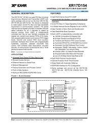
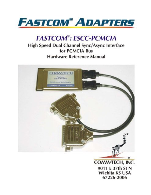
The new FASTCOM: <strong>ESCC</strong>-<strong>PCMCIA</strong> is a very high speed, dual channel, synchronous/asynchronous serial<br />
communications adapter based upon the Siemens 82532 Enhanced Serial Communication Controller (<strong>ESCC</strong>),<br />
and is designed for use in a <strong>PCMCIA</strong> Type II slot.<br />
The FASTCOM: <strong>ESCC</strong>-<strong>PCMCIA</strong> is designed to support data rates up to 10 Mbits/second (maximum data rates<br />
are affected by many factors, including computer performance, cable quality, and software overhead), and to<br />
reduce the hardware and software overhead needed for serial communications. Each sync/async channel on the<br />
FASTCOM: <strong>ESCC</strong>-<strong>PCMCIA</strong> has its own DPLL encoder/decoder and programmable protocol support. In addition,<br />
a built-in 64 byte FIFO provides the FASTCOM: <strong>ESCC</strong>-<strong>PCMCIA</strong> with a very high throughput as well as requiring<br />
less system CPU time than any other HDLC adapter. The FASTCOM: <strong>ESCC</strong>-<strong>PCMCIA</strong> directly supports HDLC,<br />
X.25 LAP B, ISDN LAP D, SDLC, ASYNC, and BISYNC protocols, and features a high speed RS-422/RS-485<br />
interface. HDLC features include choice of CRC polynomial (CRC-CCITT or CRC-32), expanded line encoding<br />
methods (FM and Manchester), and preamble transmission.<br />
Many engineers have avoided using synchronous communication adapters because of their programming<br />
complexity. The FASTCOM: <strong>ESCC</strong>-<strong>PCMCIA</strong> provides high-speed data communications to designers and<br />
engineers, while greatly reducing development time and system complexity.<br />
The FASTCOM: <strong>ESCC</strong>-<strong>PCMCIA</strong> is also available in a PC/104 bus version (FASTCOM: <strong>ESCC</strong>-104), a PCI bus<br />
version (FASTCOM: <strong>ESCC</strong>-PCI), and an ISA bus version (FASTCOM: <strong>ESCC</strong>-ISA).<br />
The following diagram illustrates the basic structure of the FASTCOM: <strong>ESCC</strong>-<strong>PCMCIA</strong>:<br />
<strong>PCMCIA</strong> SLOT<br />
<strong>PCMCIA</strong><br />
INTERFACE<br />
CONTROLLER<br />
82532<br />
COMMUNICATION<br />
CONTROLLER<br />
CHANNEL 1 (OF 2)<br />
RS-422/485<br />
DRIVERS/RECEIVERS<br />
SD+<br />
SD-<br />
RD+<br />
RD-<br />
RT+<br />
RT-<br />
TT+<br />
TT-<br />
1
2<br />
SPECIFICATIONS:<br />
COMMUNICATION<br />
CONTROLLER: SIEMENS 82532<br />
DRIVERS/RECEIVERS: RS-422/RS-485<br />
BUS INTERFACE: <strong>PCMCIA</strong> Type II slot<br />
ENVIRONMENT:<br />
Operating Temperature Range: 0 to 70 C<br />
Humidity: 0 to 90% (non-condensing)<br />
FEATURES:<br />
High speed, up to 10Mbits/s<br />
Much easier to program and use than other HDLC adapters<br />
Supports HDLC, SDLC, ISDN LAP D, and X.25 LAP B, ASYNC, BISYNC<br />
Drivers: RS-422/RS-485 multi-drop<br />
Excellent noise rejection, cable lengths up to 4000 feet<br />
Use low cost "twisted pair" cable<br />
RS-485 mode<br />
Up to 32 FASTCOM: <strong>ESCC</strong>-<strong>PCMCIA</strong> adapters can share the same "twisted pair"<br />
Driver control is automatic (via the RTS line)<br />
Serial Interface:<br />
Internal or External Clock Source<br />
Asynchronous, Monosync/Bisync, and HDLC/SDLC data formatting.<br />
1X (isosynchronous) or 16X oversampling for Asynchronous format<br />
Different modes of data encoding (NRZ,NRZI,FM0,FM1,Manchester)<br />
CRC-CCITT or CRC-32 (for HDLC/SDLC modes)<br />
CRC-CCITT or CRC-16 (for BISYNC mode)<br />
Collision resolution<br />
Programmable bit inversion<br />
Transparent RD/SD of data bytes without HDLC framing<br />
Protocol Support (HDLC/SDLC):<br />
Types of protocol support - Automatic, Manual, Transparent<br />
Handling of bit-oriented functions in all modes<br />
Handling of I and S frames in Auto mode<br />
Modulo 8 and 128 operation<br />
64 byte FIFOs per direction<br />
Storage of up to 17 short received frames
FASTCOM: <strong>ESCC</strong>-<strong>PCMCIA</strong><br />
PACKING LIST:<br />
FASTCOM: <strong>ESCC</strong>-<strong>PCMCIA</strong> CARD<br />
CABLE ASSEMBLIES (2)<br />
FASTCOM CD<br />
If an omission has been made, please call technical support for a replacement.<br />
DB25 CABLE CONNECTOR DESCRIPTION<br />
DATA SIGNALS<br />
PIN# SIGNAL DESCRIPTION 422 TYPE CONNECTED TO<br />
7 GROUND GND<br />
2 TRANSMIT DATA A SD-<br />
14 TRANSMIT DATA B SD+<br />
3 RECEIVE DATA A RD-<br />
16 RECEIVE DATA B RD+<br />
CLOCK SIGNALS<br />
PIN# DESCRIPTION 422 TYPE CONNECTED TO<br />
24 TRANSMIT CLOCK OUT A TT+<br />
11 TRANSMIT CLOCK OUT B TT-<br />
17 RECEIVE CLOCK IN A RT+<br />
9 RECEIVE CLOCK IN B RT-<br />
TT-<br />
RT-<br />
GND<br />
RD-<br />
SD-<br />
13<br />
12<br />
11<br />
10<br />
9<br />
8<br />
7<br />
6<br />
5<br />
4<br />
3<br />
2<br />
1<br />
25<br />
24<br />
23<br />
22<br />
21<br />
20<br />
19<br />
18<br />
17<br />
16<br />
15<br />
14<br />
TT+<br />
RT+<br />
RD+<br />
SD+<br />
3
4<br />
INSTALLATION<br />
Important: Observe Electrostatic Discharge (ESD) precautions when handling the FASTCOM: <strong>ESCC</strong>-<strong>PCMCIA</strong><br />
board.<br />
1. Unpack the FASTCOM: <strong>ESCC</strong>-<strong>PCMCIA</strong>. Keep the box and static bag for warranty repair returns.<br />
2. Select an open <strong>PCMCIA</strong> Type II slot in your PC.<br />
3. After removing the blank bracket from your PC, install the FASTCOM: <strong>ESCC</strong>-<strong>PCMCIA</strong> in the PC by<br />
pressing it firmly into the slot.<br />
SOFTWARE INSTALLATION<br />
Select the link above to open the Installation Manual. Under Fastcom: <strong>ESCC</strong>-<strong>PCMCIA</strong>, select your operating<br />
system and follow the instructions. When you are finished, select Fastcom: <strong>ESCC</strong>-<strong>PCMCIA</strong> from the list at the<br />
end of the Fastcom: <strong>ESCC</strong>-<strong>PCMCIA</strong> section to return to this manual.<br />
TESTING THE INSTALLATION 1<br />
2<br />
To fully test the installation of your FASTCOM: <strong>ESCC</strong>-<strong>PCMCIA</strong>, you will<br />
need to build a "loop back plug". Materials needed are a DB25 female<br />
receptacle (solder-cup style) and a few short pieces of 20 or 24 AWG<br />
stranded wire. Jumper the pins together on the DB25 as illustrated:<br />
FASTCOM: <strong>ESCC</strong>-<strong>PCMCIA</strong> WINDOWS TEST<br />
1. Attach a loopback plug to the cable #1 (<strong>ESCC</strong>0, port 0)<br />
2. From the Start button menu, select Run and type ‘cmd’ and click OK.<br />
3<br />
4<br />
5<br />
6<br />
7<br />
8<br />
10<br />
11<br />
12<br />
13<br />
14<br />
15<br />
16<br />
17<br />
18<br />
19<br />
RT-<br />
16 RD+<br />
SD+<br />
SIGNALS<br />
9<br />
20<br />
21<br />
22<br />
23<br />
24<br />
25<br />
2 SD-<br />
3 RD-<br />
9<br />
11 TT-<br />
14<br />
17 RT+<br />
24 TT+<br />
3. Change to the appropriate directory on your PC. If you ran the software copy application, the directory is<br />
c:\escc_pcmcia. Otherwise you can run from the CD (we will assume your CD is drive D). Open a<br />
command prompt (Start->Run->cmd->OK). Change to the appropriate directory that contains the esccpcmcia<br />
software. At the prompt type:<br />
D:<br />
cd fastcom_disks\escc-pcmcia\utils<br />
4. From this directory, run: clock\setclock.exe 0 6000000<br />
5. Then run: escctest\esccptest 0 h<br />
6. You should see:<br />
Created esccdrv—<strong>ESCC</strong>0<br />
<strong>ESCC</strong> 82532 version status:82<br />
# receive buffers ready:0<br />
resetting<br />
HDLC settings
SETTINGS SUCCESSFUL:168<br />
DTR not SET<br />
DSR not SET<br />
DTR not SET<br />
DSR not SET<br />
waiting for a key<br />
read thread started<br />
status thread started<br />
7. Press the letter "a" on the keyboard. You should see:<br />
WRITEFILE esccdrv1024<br />
returned TRUE<br />
waiting for a key<br />
STATUS, Receive Frame Start<br />
STATUS, All Sent<br />
received 1025 bytes:<br />
aaaaaaaaaaaaa...(12 complete lines and one partial line of "a"s (1024 of them). The last character is not<br />
an "a".)<br />
8. Press [esc] to exit the program.<br />
You can test channel 1 in a similar manner by running ‘escctest\esccptest 1 h’<br />
Make sure that you move your loopback to cable #2 before running the test on channel 1.<br />
You can test other operating modes by changing the last letter:<br />
Async test: DX:\fastcom_disks\escc-pcmcia\utils\escctest\esccptest 0 a<br />
HDLC test: D:\fastcom_disks\escc-pcmcia\utils\escctest\esccptest 0 h<br />
Bisync test: D:\fastcom_disks\escc-pcmcia\utils\escctest\esccptest 0 b<br />
In async you will get a STATUS, Receive Timeout after the All sent message (and possibly at the beginning<br />
before you press a key).<br />
The bisync test will get a STATUS, SYN detected instead of a receive frame start message.<br />
The async test should receive 1024 bytes, displayed as 12.8 lines of the key you pressed.<br />
The HDLC test should receive 1025 bytes, displayed as 12.8 lines of the key you pressed.<br />
The bisync test should receive 1025 bytes, displayed as 12.8 lines of the key you pressed.<br />
The exceptions to this are the keys t, r, i, p and h.<br />
pressing "t" will reset the transmitter and flush the transmit queue<br />
pressing "r" will reset the receiver and flush the receive queue<br />
pressing "i" will start the timer (which will eventually result in a STATUS, Timer expired message. It takes<br />
about a minute in HDLC mode for the timer to timeout)<br />
pressing "p" will stop the timer (which will prevent the STATUS, Timer expired message)<br />
pressing "h" will issue a hunt command in bisync mode<br />
TEST #2<br />
1. Press the Start Button, select the Run command<br />
Enter: c:\escc_pcmcia\utils\esccpmfc\esccpmfc.exe<br />
Click OK<br />
2. From the main menu select Options -> Port<br />
Enter 0, click OK<br />
(this selects port 0, make sure you have your loopback on cable #1)<br />
5
6<br />
3. From the main menu select Options -> Settings<br />
(the settings dialog will open)<br />
Click OK<br />
(the TXD status indicator should turn green)<br />
4. Type a short message on the keyboard, press enter to send it.<br />
The message you typed should appear in the lower window, and the RXD, RFS, and ALLS status indicators<br />
should turn green (if it was a short message (
RS-422 / RS-485<br />
Most engineers have worked with RS-232 devices at least once in their career. If you have never worked with<br />
RS-422 or RS-485 devices, you will be pleased to know that working with the FASTCOM: <strong>ESCC</strong>-<strong>PCMCIA</strong> is not<br />
much different from working with an RS-232 device.<br />
The RS-422 standard was developed to correct some of the deficiencies of RS-232. In commercial and industrial<br />
applications, RS-232 has some significant problems. First, the cable length between RS-232 devices must be<br />
short (usually less than 50 feet at 9600 Baud). Second, many RS-232 errors are the result of cables picking up<br />
normal industrial electrical noises such as fluorescent lights, motors, transformers, and other EMF sources. Third,<br />
RS-232 data rates are functionally limited to 19.2K Baud. On the other hand, the newer RS-422 standard makes<br />
cable lengths up to 5000 feet possible and is highly immune to most industrial noises. Data rates are also<br />
improved -- the FASTCOM: <strong>ESCC</strong>-<strong>PCMCIA</strong> features data rates up to 10 Mega Baud. These improvements were<br />
made possible by differentially driving and receiving the data as opposed to the single ended method employed<br />
by the RS-232 standard. With the RS-422 standard, the transmit signal (TX in RS-232) is a differential signal<br />
consisting of SD+ and SD-; the receive signal (RX in RS-232) consists of RD+ and RD-.<br />
Another draw back of RS-232 is that more than two devices cannot share a single cable. This is also true of<br />
RS-422, and that's why the RS-485 standard was developed. RS-485 offers all of the benefits of RS-422 and<br />
also allows multiple units (up to 32) to share the same twisted pair. RS-485 is often referred to as a "multi-drop"<br />
or "two-wire, half duplex" network because the drivers (transmitters) and receivers share the same two lines. In<br />
fact, up to 32 stations can share the same "twisted pair". In order for an RS-485 system to work, only one driver<br />
(transmitter) can occupy the network at a time. This means that each station on the network must control the<br />
enabling/disabling of their drivers in order to avoid network conflicts. If two drivers engage the network at the<br />
same time, data from both will be corrupted. In RS-485 mode, the receivers are always enabled.<br />
For a more detailed description of RS-422 and RS-485, we recommend the following references:<br />
LINEAR AND INTERFACE CIRCUITS APPLICATIONS, Volume 2: Line Circuits, Display Drivers. By<br />
D.E. Pippenger and E. J. Tobaben. Published 1985 by Texas Instruments. ISBN-0-89512-185-9<br />
Note: This book may be difficult to find in a bookstore. The best place to get it is directly from Texas<br />
Instruments or from one their component dealers. Publication # SLYA002.<br />
"Driver/Receiver Family Extends Data-Link Performance", ELECTRONIC PRODUCTS, January 15, 1985.<br />
By Dale Pippenger and Joe Miller<br />
7
8<br />
TERMINATION RESISTANCE<br />
In both the RS-422 and the RS-485 mode, the receiver end of the cable between two stations must be terminated<br />
with a resistor equal to the characteristic impedance of the wire. This is to prevent signal reflections in the wire<br />
and to improve noise rejection. However, you do not need to add a terminator resistor to your cables when<br />
you use the FASTCOM: <strong>ESCC</strong>-<strong>PCMCIA</strong>. The termination resistance is built in. We have installed a<br />
terminator resistor for each receiver: between each RD+ and RD- and between CTS+ and CTS- for each<br />
channel.<br />
If you are using the FASTCOM: <strong>ESCC</strong>-<strong>PCMCIA</strong> in a multi-drop network, the termination resistor should be<br />
removed from all units except the first and last (see the RS-485 illustration below). You may order the<br />
FASTCOM: <strong>ESCC</strong>-<strong>PCMCIA</strong> without the termination resistor installed, or with a different ohm value. Observe the<br />
resistors in the following drawings and remember that they are built into the FASTCOM: <strong>ESCC</strong>-<strong>PCMCIA</strong>:
PROGRAMMABLE CLOCK GENERATOR<br />
The FASTCOM: <strong>ESCC</strong>-<strong>PCMCIA</strong> features a programmable clock generator, which offers a fully userprogrammable<br />
phase-locked loop in a single 16-pin package. The output may be changed "on the fly" to any<br />
desired frequency value between 6-200 MHz (the FASTCOM: <strong>ESCC</strong>-<strong>PCMCIA</strong> maximum is 33 MHz). The ability<br />
to dynamically change the output frequency adds a whole new degree of freedom for the designer.<br />
FEATURES<br />
• Clock outputs ranging from 6 to 200 MHz (the FASTCOM: <strong>ESCC</strong>-<strong>PCMCIA</strong> maximum is 33 MHz)<br />
• Phase-Locked Loop oscillator input derived from external reference clock (18.432 MHz on the<br />
FASTCOM: <strong>ESCC</strong>-<strong>PCMCIA</strong>)<br />
• Three-State output control disables output for test purposes<br />
• Sophisticated internal loop filter requires no external components or manufacturing tweaks as<br />
commonly required with external filters<br />
• Low power consumption makes device ideal for power- and space-critical applications<br />
• Programmable using the FASTCOM: <strong>ESCC</strong>-<strong>PCMCIA</strong> PVR register, bits 0 and 1 (see page 17)<br />
• 5V operation<br />
• High-speed CMOS technology<br />
PROGRAMMING NOTE<br />
Revision 3.2A of the Siemens 82532 utilizes both standard and enhanced modes of the Baud Rate Generator<br />
Register (BGR). In standard mode, the following formula is used to calculate the divisor for baud rate generation:<br />
k = (N+1) * 2<br />
The following hexadecimal values of N are equivalent to N equaling zero:<br />
0x000 0x100 0x200 0x300<br />
0x040 0x140 0x240 0x340<br />
0x080 0x180 0x280 0x380<br />
0x0C0 0x1C0 0x2C0 0x3C0<br />
This is a known bug of the 82532.<br />
9
10<br />
DETERMINING AND SELECTING BAUD RATES<br />
Selecting the bit rate can either be very easy or quite complicated, depending on a number of factors. The best<br />
place to start is to determine the big picture (broad perspective) and narrow down the options using the various<br />
constraints that the hardware imposes.<br />
There are four basic things that make up what the actual bitrate will be. They are:<br />
1. Register settings of the 82532 chip. These include:<br />
A. Operating mode (HDLC, Bisync, Async)<br />
1. If async is used is it truly async (oversampled BCR=1), or<br />
2. isosynchronous (async format with no oversampling).<br />
B. Clock mode (internal or external clocks)<br />
1. If internal clocks, does it use clock recovery (DPLL)<br />
2. If BGR is used is the BDF bit 1 or 0.<br />
2. The setting of the clock generator that feeds the OSC input to the 82532 (only a factor if an internal<br />
clock mode is used, i.e., BGR or DPLL is involved).<br />
3. The revision of the <strong>ESCC</strong> 82532 chip (silicon)<br />
A. The rev 3.2 silicon incorporates an enhanced baud rate mode.<br />
We will start with the simplest case. If you are using the Asynchronous data mode, then the most likely clock<br />
mode that you should use is 7b. It is possible to use the other clock modes; however, mode 7b is the most<br />
straightforward to work with. The bitrate will be determined by the output of the baud rate generator. The baud<br />
rate generator is clocked by the OSC input (which is set by the programmable clock generator). So you have:<br />
If you are not using oversampling (BCR = 0) the formula is:<br />
bitrate = (input clock / BGR)<br />
If you are using oversampling (BCR = 1 (the normal case for async)) the formula is:<br />
bitrate = (input clock / BGR)/16<br />
If BDF = 0 then BGR = 1<br />
If BDF = 1 then BGR = (N+1)*2<br />
If BDF = 1 and EBRG = 1 then BGR = (n+1)*2 m<br />
The BCR bit is in CCR1 (bit 3)<br />
The BDF bit is in CCR2 (bit 5)<br />
The EGRG bit is in CCR4 (bit 6)<br />
N = (CCR2&0xC0)
To use Master clock mode or not to use Master clock mode; that is the question.<br />
The 82532 operating in standard (non-master clock) mode uses the transmit clock source (refer to table 5 page<br />
84 of the data sheet) to run the internal timing of the chip. If your transmit clock source is running very slow or it is<br />
not running continuously (if external clock is supplied), then it is a good idea to switch to master clock mode.<br />
Each command issued to the 82532 (any write to the CMDR register) can take up to 2.5 clocks to complete. If the<br />
clock is very slow or stops from time to time, this can be a significant amount of time and allows for the possibility<br />
of a command being lost (written but not executed, because a previous command is not complete). If your baud<br />
rate is slow (
12<br />
The input clock will depend on the clock mode. It is usually either the OSC input or the RXCLK (RT+/-) input (see<br />
table 5 page 84 of the 82532 data sheet).<br />
If BDF = 1 BGR = 1<br />
If BDF = 0 BGR = (N+1)*2<br />
If BDF = 0 and EBRG = 1 BGR = (n+1)*2^m (V 3.x of the 82532 silicon only)<br />
The BDF bit is in CCR2 (bit 5)<br />
N = (CCR2&0xC0)
Important Register Settings<br />
MODE = 0x88<br />
This sets the 82532 in transparent HDLC mode 0. This will use a frame structure as:<br />
0x7E | data | CRC | CRC | 0x7E<br />
No address recognition is used<br />
The timer is in external mode<br />
RTS is handled by the 82532 (active while transmitting)<br />
Timer resolution is 32768 clocks<br />
CCR0 = 0xC0<br />
This sets the 82532 in power up mode<br />
Master clock mode is enabled<br />
NRZ is the encoding type<br />
HDLC mode is selected<br />
CCR1 = 0x10<br />
This selects clock mode 0(b)<br />
The tx pin is using a push-pull output (required)<br />
Time fill is all ‘1’s (idle pattern = 0xff)<br />
CCR2 = 0x38<br />
This selects the BGR = (N+1)*2 divisor<br />
Selects txclk to be an output<br />
Selects clock mode 0b (the B part)<br />
Enables the CRC-CCITT polynomial<br />
CCR3 = 0x00<br />
No preamble output<br />
CRC reset level = 0xffff<br />
CRC is in use (both transmit and receive), not including CRC in received Data (not returned to the<br />
user)<br />
Not using extended window for DPLL<br />
CCR4 = 0x00<br />
Not using master clock/4<br />
Not using enhanced baud rate generator<br />
FIFO threshold is 32 bytes (mandatory for NT driver in HDLC mode)<br />
BGR = 0xBF<br />
This sets the output clock rate to 19200 (given that the input clock was previously set to 7.3728<br />
MHz, and the above registers are set as shown)<br />
CCR0, CCR1, CCR4 and BGR are the most critical registers that effect the bitrate, the rest are shown for<br />
completeness, and, depending on the system, you can easily change some parameters without affecting the<br />
bitrate (i.e., line encoding, address recognition, crc type, etc.).<br />
And now for something a bit more difficult:<br />
Let’s say that you want to run one channel asynchronously at 38400 bps, and the second channel synchronously<br />
using HDLC at 2 Mbps. How would you go about it?<br />
Start with the fastest bit rate and determine if there is an external clock that is received with that data or if the<br />
clock must be recovered (DPLL mode). Let’s say that you want to recover the clock from the data (there are no<br />
clock lines in the system), and that the data is Manchester encoded. To get a 2 Mbps clock rate using a DPLL we<br />
will need to use the bitrate = (input clock/1)/16 function. This will require a 32 MHz input clock. To get this input<br />
13
14<br />
clock run:<br />
setclock.exe 0 32000000<br />
using the following register settings:<br />
MODE = 0x88<br />
CCR0 = 0x98<br />
CCR1 = 0x16<br />
CCR2 = 0x18<br />
CCR3 = 0x00<br />
CCR4 = 0x00<br />
The receive source will be recovered from the data stream. The transmit source will be the BGR/16 output.<br />
Now for the async channel. We are locked into the 32 MHz input clock, so we will try to find a value for N that<br />
gets our desired 38400 bps:<br />
38400 = (32E6/16)/((N+1)*2)<br />
N = 25.04 (we cannot attain non-integer values for N).<br />
If we use N = 25 we would get:<br />
bitrate = (32E6/16)/(25+1)*2 = 38462 bps<br />
If we use N = 26 we would get:<br />
bitrate = (32E6/16)/(26+1)*2 = 37037 bps<br />
Using the closest value and setting the registers to<br />
MODE = 0x08,<br />
CCR0 = 0xC3,<br />
CCR1 = 0x1F,<br />
CCR2 = 0x38,<br />
CCR3 = 0x00,<br />
CCR4 = 0x80, and<br />
BGR = 0x19<br />
will yield an asynchronous data format (with 16X oversampling) at about 38400 bps.<br />
If later you decide that you need to get 115200 bps on the async channel you will find:<br />
115200 = (32E6/16)/((N+1)*2)<br />
N = 7.68<br />
Using N = 7<br />
bitrate = (32E6/16)/((7+1)*2) = 125000 bps<br />
Using N = 8<br />
bitrate = (32E6/16)/((8+1)*2) = 111111 bps<br />
The ideal situation would be to adjust the 32 MHz clock such that the deviation between the desired and actual<br />
rates is spread between both channels (with the DPLL recovering the clock, the actual clock that feeds it is not as<br />
critical as a clock mode that uses the clock directly).<br />
Clock modes 0b, 3b, 4, and 7b are more sensitive to the selected rate in synchronous modes, as there is no<br />
oversampling. The rate you select is the rate you will get, whereas oversampling modes (using the DPLL or<br />
ASYNC BCR) are more tolerant to differences between the rate you set and the rate you want.
Clocking Concept Block Diagram<br />
CCR4<br />
MCK=0<br />
1<br />
Clock<br />
Generator<br />
Oscillator<br />
4:1<br />
RxD<br />
f OSC f DPLL f BRG f BRG/16 f RxCLK f TxCLK<br />
f OSC<br />
CCR0<br />
MCE=1<br />
0<br />
f DPLL<br />
4 3a<br />
7a<br />
0b<br />
6a/b<br />
7a/b<br />
f BRG<br />
0b<br />
3b<br />
7b<br />
BRG<br />
f BRG/16<br />
RT+<br />
RT-<br />
RxCLK<br />
2b<br />
6b<br />
2a/b<br />
3a/b<br />
DPLL 16:1<br />
f RxCLK<br />
1<br />
5<br />
f TRM<br />
f TxCLK<br />
0a<br />
2a<br />
6a<br />
f OSC<br />
f DPLL<br />
f BRG<br />
4 2a/b 3b<br />
3a 7b<br />
6a/b<br />
7a<br />
f REC<br />
Core Transmitter Receiver<br />
TT+<br />
TT-<br />
TxCLK<br />
f RxCLK<br />
0a/b<br />
1<br />
5<br />
15
16<br />
TECHNICAL SUPPORT<br />
<strong>Commtech</strong> provides extensive technical support and application suggestions. Most of the problems that occur with the<br />
FASTCOM: <strong>ESCC</strong>-<strong>PCMCIA</strong> can be corrected by double-checking the switch positions, your cables and your program. We<br />
recommend that you build the loop back plug that is described in the Programming section of this manual. With that plug, you<br />
can quickly isolate the problem to the board, cables, or software.<br />
If you still have unresolved questions, use the following procedure to get technical support:<br />
1. Call our Technical Support Staff at (316) 636-1131. They are on duty from 9:00 AM to 5:00 PM Central Time.<br />
2. Ask for technical support for the FASTCOM: <strong>ESCC</strong>-<strong>PCMCIA</strong>. Be ready to describe the problem, your computer<br />
system, your application, and your software.<br />
3. If necessary, our staff will give you an RMA number (Return Material Authorization). Use this number on the mailing<br />
label and in all references to your board. Put the board back in its static bag and in its box. Ship the board back to us<br />
as directed.<br />
4. If you prefer, you may FAX a description of the problem to us at (316) 636-1163, or we can be reached on the Internet<br />
at http://www.commtech-fastcom.com/TechSupport.html or by email at techsupport@commtech-fastcom.com.<br />
FASTCOM LIMITED LIFETIME WARRANTY<br />
<strong>Commtech</strong>’s entire FASTCOM product line is covered by a limited lifetime warranty against defects in workmanship. This<br />
warranty is available only to the original purchaser and only covers defects in our workmanship. Any FASTCOM board that is<br />
returned to <strong>Commtech</strong> will, at the option of <strong>Commtech</strong>, be repaired or replaced at no charge -- except for circumstances<br />
excluded by this warranty.<br />
A Return Materials Authorization (RMA) number must be obtained from <strong>Commtech</strong> before a return will be accepted. Please<br />
contact us via telephone or email to obtain an RMA number.<br />
You are responsible for shipping charges when you return a FASTCOM board to <strong>Commtech</strong>. We will pay the shipping<br />
charges to send the board back to you if a defect in workmanship is found. However, if no defect in workmanship is found, or<br />
the board is not found to be defective, or the any of the following warranty exclusions occur, you will be responsible for<br />
shipping charges both ways.<br />
Warranty Exclusions<br />
This warranty does not cover problems or damage resulting from, but not limited to, the following:<br />
1. Any modification, misuse, abuse, disassembly, misapplication, or unauthorized repair by anyone other than<br />
<strong>Commtech</strong>.<br />
2. Any improper operation, including any use not in accordance with any verbal product instructions or documentation.<br />
3. Connection to an improper voltage supply or ESD damage.<br />
4. Any other cause not related to workmanship.<br />
Non-Warranty Repairs<br />
We can provide a quote for non-warranty repairs upon request.<br />
If any <strong>Commtech</strong> product is damaged such that it cannot be repaired, you can return it to <strong>Commtech</strong> for replacement under<br />
our Non-Repairable Replacement policy, regardless of the cause of damage. <strong>Commtech</strong> will replace the unit at 60% of the<br />
then-current list price.<br />
Limitation of Liability<br />
<strong>Commtech</strong> shall not be liable for any special, incidental, indirect, or consequential damages whatsoever, including but not<br />
limited to loss of profits, revenue, or data (whether direct or indirect), or commercial loss for breach of any express or implied<br />
warranty on your product even if <strong>Commtech</strong> has been advised previously of the possibility of such damages. <strong>Commtech</strong> does<br />
not warrant that its products will work in every system or every system configuration. We do not warrant that our products will<br />
be suitable for your application. If you are dissatisfied with our product, contact customer service to arrange for a return of our<br />
product and refund of your money. <strong>Commtech</strong>’s liability, in any case, is limited to the original product purchase price and is<br />
available to the original customer only.
APPENDIX A<br />
SAB 82532<br />
TECHNICAL DATA<br />
17