µP-controlled mixer board No more noisy controls – ever ... - WebHTB
µP-controlled mixer board No more noisy controls – ever ... - WebHTB
µP-controlled mixer board No more noisy controls – ever ... - WebHTB

Create successful ePaper yourself
Turn your PDF publications into a flip-book with our unique Google optimized e-Paper software.
either or both outputs. A standard<br />
3-wire serial interface is used as well as<br />
a Data Out terminal to facilitate daisychaining<br />
of multiple <strong>mixer</strong> ICs.<br />
The control signal for the <strong>mixer</strong><br />
<strong>board</strong> is provided by a Type ST62T25<br />
microcontroller. This devices rapidly<br />
scans the potential at the wipers of the<br />
potentiometers and converts this information<br />
into an 8-bit code. The controller<br />
also monitors the position of<br />
two switches at each input so that the<br />
operator can<br />
arrange for the<br />
relevant input signal<br />
to be applied<br />
to the left-hand or<br />
right-hand channel<br />
or both. This<br />
information is<br />
contained in the<br />
control code.<br />
THE<br />
SSM2163<br />
The SSM2163<br />
consists of an analogue<br />
(signal processing)<br />
section<br />
and a digital (control)<br />
section.The<br />
channel attenuation<br />
level and<br />
<strong>mixer</strong> functions<br />
are <strong>controlled</strong> by<br />
digital registers,<br />
which are loaded<br />
via a serial interface.<br />
A hardware<br />
mute input is<br />
included to asynchronously<br />
force all inputs into the<br />
muted state.<br />
Analogue section<br />
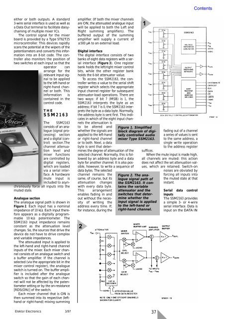
The analogue signal path is shown in<br />
Figure 2. Each input has a nominal<br />
impedance of 10 kΩ. Each input therefore<br />
appears as a digitally programmable<br />
10 kΩ potentiometer. The<br />
SSM2163 input impedance remains<br />
constant as the attenuation level<br />
changes. So, the sources that drive the<br />
device do not have to drive complex<br />
and variable impedances.<br />
The attenuated input is applied to<br />
the left-hand and right-hand channel<br />
inputs of the <strong>mixer</strong>. Each <strong>mixer</strong> channel<br />
consists of an analogue switch and<br />
a buffer amplifier. If the channel is<br />
selected (via the appropriate bit in the<br />
<strong>mixer</strong> control register), the analogue<br />
switch is turned on. The buffer amplifier<br />
is included after the analogue<br />
switch so that the gain of each channel<br />
will not be affected by the potentiometer<br />
setting or by the on-resistance<br />
[RDS(ON)] of the switch.<br />
Each <strong>mixer</strong> channel that is ON is<br />
then summed into its respective (lefthand<br />
or right-hand) mixing summing<br />
Elektor Electronics 3/97<br />
amplifier. (If both the <strong>mixer</strong> channels<br />
are ON, the attenuated analogue input<br />
will be applied to both the Left and<br />
Right summing amplifiers). The<br />
buffered output of the summing<br />
amplifier will supply a current of<br />
±500 µA to an external load.<br />
Digital interface<br />
The digital interface consists of two<br />
banks of eight data registers with a serial<br />
interface (Figure 3). One register<br />
bank holds the left/right <strong>mixer</strong> control<br />
bits, while the other register bank<br />
holds the 6-bit attenuator value.<br />
To access the SSM2163, the controller<br />
writes a value to the serial shift<br />
register which selects the appropriate<br />
input channel register for subsequent<br />
attenuator-load operations. There are<br />
two ways: if bit 7 (MSB) is 1, the<br />
SSM2163 interprets the byte as an<br />
address; if bit 7 is 0, the SSM2163 interprets<br />
the byte as a data byte. <strong>No</strong>rmally,<br />
the address byte is sent first. This indicates<br />
in which of the eight input chan-<br />
nels the attenuation is<br />
to be altered and<br />
whether the signals are<br />
applied to the left-hand<br />
or right-hand channel<br />
or to both. Next, a data<br />
byte is sent that determines<br />
the degree of attenuation of the<br />
selected channel. <strong>No</strong>rmally, this is followed<br />
by an address byte and a data<br />
byte for another channel. It is also possible,<br />
how<strong>ever</strong>, to write a sequence of<br />
data bytes. The selected<br />
channel remains the<br />
same, of course, but its<br />
attenuation changes<br />
with <strong>ever</strong>y data byte.<br />
This arrangement<br />
enables fading in and<br />
out without the necessity<br />
of writing the<br />
address <strong>ever</strong>y time. If,<br />
for instance, during the<br />
2<br />
1<br />
Figure 1. Simplified<br />
block diagram of digitally<br />
<strong>controlled</strong> audio<br />
<strong>mixer</strong> Type SSM2163.<br />
Figure 2. The analogue<br />
signal path of<br />
the SSM2163. It contains<br />
the variable<br />
attenuator and the<br />
switches that determine<br />
whether the<br />
input signal is applied<br />
to the left-hand or<br />
right-hand channel.<br />
fading out of a channel<br />
a series of values is sent<br />
to the same address, a<br />
single write operation<br />
to the address register<br />
suffices.<br />
When the mute input is made high,<br />
all channels are muted: this action<br />
does not affect the set attenuation values,<br />
which are retained. Switch-on<br />
37<br />
noises are obviated by<br />
forcing all inputs into<br />
the muted state at that<br />
instant.<br />
Serial data control<br />
inputs<br />
The SSM2163 provides<br />
a simple 3- or 4-wire<br />
serial interface. Data is<br />
input on the DATA IN