
You also want an ePaper? Increase the reach of your titles
YUMPU automatically turns print PDFs into web optimized ePapers that Google loves.
EF<br />
User Guide<br />
CTNet<br />
Part Number: 0460-0025-07<br />
Issue Number: 7<br />
www.controltechniques.com
General Information<br />
The manufacturer accepts no liability for any consequences resulting from inappropriate,<br />
negligent or incorrect installation or adjustment of the optional operating parameters of<br />
the equipment or from mismatching the variable speed drive (Drive) with the motor.<br />
The contents of this guide are believed to be correct at the time of printing. In the<br />
interests of a commitment to a policy of continuous development and improvement, the<br />
manufacturer reserves the right to change the specification of the product or its<br />
performance, or the contents of this guide, without notice.<br />
All rights reserved. No parts of this guide may be reproduced or transmitted in any form<br />
or by any means, electrical or mechanical including photocopying, recording or by an<br />
information storage or retrieval system, without permission in writing from the publisher.<br />
Drive software version<br />
This product is supplied with the latest version of user-interface and machine control<br />
software. If this product is to be used in a new or existing system with other Drives, there<br />
may be some differences between their software and the software in this product. These<br />
differences may cause this product to function differently. This may also apply to Drives<br />
returned from a Control Techniques Service Centre.<br />
If there is any doubt, contact a Control Techniques Drive Centre.<br />
Copyright © 24 March 2005 Control Techniques Drives Ltd.<br />
Issue Code: 7<br />
Hardware: Rev C and Rev D
Contents<br />
1 Electrical Installation 5<br />
1.1 CTNet network overview 5<br />
1.2 CTNet hardware revision 6<br />
1.3 CTNet segment design 7<br />
1.4 CTNet wiring practices 14<br />
1.5 CTNet device connections 15<br />
1.6 CTNet cable 30<br />
1.7 CTNet segment termination 30<br />
1.8 CTNet shield connections 31<br />
1.9 Joining CTNet cables together 33<br />
1.10 Other wiring tips 35<br />
2 Getting Started 36<br />
2.1 Unidrive 36<br />
2.2 Unidrive SP 37<br />
2.3 Mentor II 37<br />
2.4 CTNet I/O coupler 38<br />
2.5 CTNet HMI (CTIU200) 39<br />
2.6 CTNet Hub 39<br />
2.7 CTNet PC cards 39<br />
2.8 Installing PCI and PCMCIA card drivers 40<br />
2.9 Installing the PC ISA card 41<br />
3 Cyclic Data 42<br />
3.1 What is cyclic data? 42<br />
3.2 Cyclic data rate 43<br />
3.3 Configuring cyclic data links 43<br />
3.4 “Easy mode” cyclic data 44<br />
3.5 Mapping conflicts 46<br />
4 Non-Cyclic Data 48<br />
4.1 Non-cyclic message handling 48<br />
4.2 Non-cyclic message delays 49<br />
4.3 Reading parameters over CTNet 49<br />
4.4 Writing parameters over CTNet 49<br />
4.5 Check if node exists 49<br />
5 Diagnostics 50<br />
5.1 CTNet status indication 50<br />
5.2 CTNet configuration errors 52<br />
5.3 CTNet advanced diagnostics 53<br />
5.4 Solving network reconfiguration problems 59<br />
5.5 Viewing CTNet signals using an oscilloscope 61<br />
5.6 Overloading a node 63<br />
CTNet User Guide<br />
Issue Number: 7 www.controltechniques.com
6 Advanced Features 65<br />
6.1 Automatic sync node assignment 65<br />
6.2 Editing cyclic data links 65<br />
6.3 Enabling and disabling cyclic data links 65<br />
6.4 EVENT task trigger on UD70 66<br />
6.5 EVENT task trigger on SM-Applications 67<br />
6.6 CTNet priority level on SM-Applications 67<br />
7 Legacy CTNet Hardware 68<br />
7.1 Basic segment limitations 68<br />
7.2 CTNet wiring practices 69<br />
7.3 Mixing CTNet hardware 69<br />
7.4 CTNet drivers for Windows 95 70<br />
CTNet User Guide<br />
www.controltechniques.com Issue Number: 7
1 Electrical Installation<br />
1.1 CTNet network overview<br />
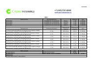
A CTNet network comprises of one or more segments that are linked together by a hub.<br />
A typical layout of a CTNet network is shown in Figure 1-1. Each segment has a<br />
termination resistor fitted at each end, and each segment meets the limits specified in<br />
section 1.3 CTNet segment design on page 7.<br />
Figure 1-1 Example CTNet network layout<br />
Segment 1<br />
Table 1.1 CTNet network terminology<br />
Term Definition<br />
network<br />
segment<br />
trunk cable<br />
termination<br />
resistor<br />
Segment 3<br />
indicates position of termination resistors<br />
Segment 2<br />
One or more segments joined together using hubs to extend the total cable length<br />
and/or increase the total number of nodes on the network.<br />
Two or more nodes connected to a length of CTNet cable, with an 82Ω 1% 0.25W<br />
termination resistor fitted at each end. The cable must run from node to node as<br />
drop lengths are not permitted on CTNet.<br />
The length of cable that connects nodes together to create a segment. The trunk<br />
cable must run from node-to-node-to-node; drop lengths of cable are not allowed<br />
on a CTNet segment.<br />
82Ω 1% 0.25W resistors that must be connected between the data lines (“A” and<br />
“B”) at the end of each segment to prevent pulse reflections. A termination resistor<br />
should be fitted if there is only one CTNet cable going to a node.<br />
CTNet User Guide 5<br />
Issue Number: 7 www.controltechniques.com
Table 1.1 CTNet network terminology<br />
Term Definition<br />
active node<br />
passive node<br />
drop length<br />
1.2 CTNet hardware revision<br />
NOTE<br />
All new CTNet devices are marked with a hardware revision level. Rev D is the up-todate<br />
hardware revision, but some devices have the intermediate Rev C hardware fitted.<br />
All Rev C devices will eventually be updated to incorporate the Rev D hardware.<br />
1.2.1 Revision D hardware<br />
Active nodes produce an electrical load on the segment, and require a node<br />
address to be assigned, as they take part in the token ring bus arbitration system.<br />
The maximum number of active nodes that can be connected on a CTNet network<br />
is 255.<br />
Passive nodes produce an electrical load on the segment, but do not require a node<br />
address to be assigned as they do not take part in the token ring bus arbitration<br />
system. They must be included when considering the number of nodes connected<br />
to a segment.<br />
A branch or spur of cable (terminated or unterminated) off the main trunk run, not<br />
allowed on a CTNet network. A drop length is present if there are 3 or more CTNet<br />
cables connected to a single node.<br />
Table 1.2 CTNet Rev C and Rev D hardware devices<br />
Device Reference code Revision<br />
Unidrive CTNet,Unidrive,UD75,Rev D 80700000005701<br />
Unidrive SP<br />
SM-Applications (All modules have Rev<br />
D CTNet hardware)<br />
All<br />
Mentor II CTNet,Mentor,MD29AN,Rev D 80100000006201<br />
CTNet I/O Coupler CTNet,BK7200 I/O Coupler,Rev C 4500-0089<br />
CTIU200 CTNet,CTIU,SmartStack Rev C 4500-0088<br />
Hub CTNet, 3 Port Hub,Rev D 4500-0082<br />
PCI card CTNet,PCI Card,Rev D 4500-0085<br />
PCI/PCIX card<br />
CTNet,PCI/PCIX Card, Rev D, replaces<br />
4500-0085<br />
4500-0085-1<br />
PCMCIA card CTNet,PCMCIA Card+MAU,Rev D 4500-0086<br />
PC ISA card CTNet,ISA Card,Rev D 4500-0084<br />
Hybrid Hub CTNet,3 Port Hybrid Hub,Rev D 4500-0083<br />
Fibre Optic Repeater CTNet,Fib Optic Repeater,Rev D 4500-0081<br />
CTNet MAU only CTNet,PCMCIA MAU only,Rev D 4500-0090<br />
If a device and revision level is not listed in Table 1.2, refer to section 7 Legacy CTNet<br />
Hardware on page 68.<br />
CTNet Rev D hardware has been introduced to improve the overall<br />
N<br />
performance of CTNet, and all Rev D devices are marked with the new<br />
CTNet conformance logo. Rev D hardware uses an improved output<br />
driver stage to give higher voltage pulses, and a higher impedance input stage to<br />
reduce the load applied to the network by each node. The overall effect is to increase<br />
the number of nodes and/or total length of cable that be used for a single network<br />
segment. The maximum permitted cable length can also be increased by reducing the<br />
number of nodes on a segment, and vice versa.<br />
6 CTNet User Guide<br />
www.controltechniques.com Issue Number: 7
Rev D hardware allows a mathematical model to be applied to a segment design to<br />
determine if the combination of nodes and cable length is within the CTNet<br />
specifications for the required data rate. The model covers data rates of 5.0 Mbit/s, 2.5<br />
Mbit/s and 1.25 Mbit/s. The table below gives some example specifications that can be<br />
met with a segment consisting entirely of CTNet Rev D hardware devices.<br />
Table 1.3 Example segment specifications<br />
Data rate (Mbit/s)<br />
5 nodes<br />
Total cable length (m)<br />
10 nodes 15 nodes 20 nodes<br />
5.0 140 100 75 44<br />
2.5 250 200 150 100<br />
1.25 340 275 200 135<br />
1.2.2 Revision C hardware<br />
CTNet Rev C hardware uses identical output driver and input receiver<br />
stages as Rev D hardware, but it uses the old CTNet pulse transformer.<br />
The lower inductance of the old-style pulse transformer means that<br />
fewer Rev C nodes can be connected to a CTNet segment than Rev D devices. Rev C<br />
and Rev D devices can be mixed on a network segment without problem, but the higher<br />
loading factor of Rev C hardware must be taken in to account when checking the overall<br />
design of the CTNet segment. (See section 1.3.1 for full details.)<br />
1.3 CTNet segment design<br />
NOTE<br />
N<br />
In an ideal world, the CTNet transmitter stage would have zero output impedance,<br />
CTNet cable would have zero resistance, capacitance and inductance, and CTNet<br />
receiver stages would have infinite input impedance. This would allow any number of<br />
nodes to be connected to a segment of any length. Unfortunately, as with all real-world<br />
communication systems, this is not the case.<br />
A CTNet segment has limitations on the number of nodes and total length of cable that<br />
can be connected. In general, more nodes means less cable and vice versa, so the<br />
arrangement of segment and placement of hubs needs to be carefully considered when<br />
designing the network.<br />
The configuration of a CTNet network can be checked by calculating the Segment Load<br />
Factor (KSL) and Insertion Loss Factor (KIL) for each segment. If both KSL and KIL are<br />
within specifications for ALL segments, the CTNet network will run without problem.<br />
It is possible that a network configuration that is outside the specified limits may work<br />
without any apparent problem. However, Control Techniques will not guarantee reliable<br />
operation of a CTNet network if it does not comply to all specifications listed in this<br />
manual. Such a network is also likely to be sensitive to electrical interference.<br />
All devices connected to a segment MUST be Rev C or Rev D hardware to use the<br />
Segment Loss Factor (K SL) and Insertion Loss Factor (K IL) equations and graphs. All<br />
CTNet Rev C and Rev D devices are listed in Table 1.2.<br />
CTNet User Guide 7<br />
Issue Number: 7 www.controltechniques.com
1.3.1 Segment Load Factor<br />
The Segment Load Factor determines the maximum number of nodes that can be<br />
connected on a single segment of network, irrespective of network length.<br />
NOTE<br />
When calculating the Segment Load Factor and Insertion Loss Factors, each connected<br />
hub and repeater port must be counted as a node for that segment.<br />
KSL =<br />
( NRevD × KRevD) + ( NRevC × KRevC) where:<br />
KSL =Segment Load Factor.<br />
NRevD =total number of Rev D devices on the network segment.<br />
KRevD =load factor for a single Rev D device for a given data rate.<br />
NRevC =total number of Rev C devices on the network segment.<br />
KRevC =load factor for a single Rev C device for a given data rate.<br />
The maximum permitted values of KSL are given in Figure 1.4.<br />
Table 1.4 Segment Load Factors<br />
Data Rate<br />
(Mbit/s)<br />
Maximum<br />
Segment Load<br />
Factor (K SL )<br />
Rev D Device<br />
Load Factor<br />
(K RevD )<br />
Rev C Device<br />
Load Factor<br />
(K RevC )<br />
1.25 100 5.00 9.09<br />
2.5 100 3.29 6.09<br />
5.0 100 0.53 0.97<br />
To check that the Segment Load Factor (KSL ) is suitable for a given CTNet segment<br />
arrangement:<br />
1. Specify the network data rate.<br />
2. Determine the total number of Rev C (NRevC) and Rev D devices. (NRevD) 3. Plot the point on the Segment Load Factor Graph (Figure 1-2) where NRevD and<br />
NRevC intersect.<br />
4. If the point of intersection is above the plotted line for the specified data rate, the<br />
Segment Load Factor is too high, and CTNet operation cannot be guaranteed. Split<br />
the segment (using a hub) and repeat steps 1 to 3 for each segment.<br />
5. If the point of intersection is on or below the plotted line for the specified data rate,<br />
the Segment Load Factor is within the specified limits. Check the Insertion Loss<br />
Factor to see if segment arrangement is valid. (See section 1.3.2.)<br />
8 CTNet User Guide<br />
www.controltechniques.com Issue Number: 7
NOTE<br />
Total Number of Rev D Nodes (NRevD)<br />
30<br />
28<br />
26<br />
24<br />
22<br />
20<br />
18<br />
16<br />
14<br />
12<br />
10<br />
8<br />
6<br />
4<br />
2<br />
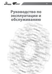
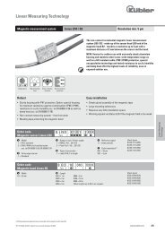
Figure 1-2 Segment Load Factor graph<br />
Segment Load Factor (K SL)<br />
0<br />
0 2 4 6 8 10 12 14 16<br />
Total Number of Rev C Nodes (NRe vC)<br />
2.5 Mbit/s<br />
1.25 Mbit/s<br />
At 5.0 Mbit/s, the calculation shows that 188 Rev D or 100 Rev C nodes could be<br />
connected to a single segment, but this will be limited by the Insertion Loss Factor. (See<br />
section 1.3.2.) As the Segment Load Factor is not a limiting factor at 5.0 Mbit/s, this line<br />
is not plotted in Figure 1-2, allowing a clearer scale to be used for the 2.5 Mbit/s and 1.25<br />
Mbit/s data rates.<br />
CTNet User Guide 9<br />
Issue Number: 7 www.controltechniques.com
1.3.2 Insertion Loss Factor<br />
The Insertion Loss Factor (KIL) determines the maximum length of cable that can be<br />
used on a network segment for a given number of nodes. Rev C and Rev D nodes have<br />
the same Insertion Loss Factor, so they can be considered to be identical for the<br />
purpose of calculating the Insertion Loss Factor.<br />
KIL =<br />
( ( Ntotal – 1)<br />
× KN) + ( Ltotal × KC) where<br />
KIL =insertion loss factor.<br />
Ntotal =total number of nodes (NRevD + NRevC ) on the network segment.<br />
KN =insertion loss per node for network data rate.<br />
Ltotal =total length of cable (in metres) on the network segment.<br />
KC =insertion loss per metre of cable for network data rate.<br />
The maximum permitted Insertion Loss values are given in Table 1.5.<br />
Table 1.5 Insertion Loss values<br />
Data rate<br />
(Mbit/s)<br />
Maximum Insertion<br />
Loss Factor (K IL )<br />
Node insertion<br />
loss (K N )<br />
Cable insertion loss<br />
per metre (K C )<br />
1.25 1000 34.3 2.50<br />
2.5 1000 34.6 3.42<br />
5.0 1000 38.5 6.04<br />
To calculate the Insertion Loss Factor for a given CTNet segment:<br />
1. Specify the network data rate.<br />
2. Count the total number of nodes (Ntotal) on the segment. Hub and repeater ports<br />
must be included.<br />
3. Determine the total length of cable (Ltotal ) on the segment.<br />
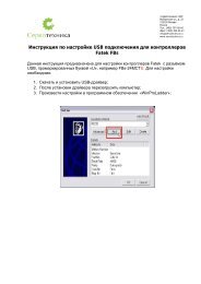
4. Plot the point on the Insertion Loss Factor Graph (Figure 1-3) where Ntotal and Ltotal intersect.<br />
5. If the point of intersection is above the plotted line for the specified data rate, the<br />
Insertion Loss Factor is too high, and correct CTNet operation cannot be<br />
guaranteed. The segment will need to be split (using a hub) to bring the Insertion<br />
Loss Factor within the specified limits.<br />
6. If the point of intersection is on or below the plotted line for the specified data rate,<br />
the Insertion Loss Factor is within the specified limits, and the segment<br />
arrangement is acceptable.<br />
10 CTNet User Guide<br />
www.controltechniques.com Issue Number: 7
Maximum Segment Length (Ltotal) in metres<br />
400<br />
350<br />
300<br />
250<br />
200<br />
150<br />
100<br />
50<br />
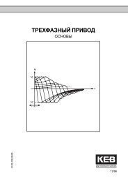
Figure 1-3 Insertion Loss Factor graph<br />
Insertion Loss Factor (K IL)<br />
0<br />
2 4 6 8 10 12 14 16 18 20 22 24 26 28 30<br />
Total Number of Nodes (Ntotal)<br />
5.0 Mbit/s<br />
2.5 Mbit/s<br />
1.25 Mbit/s<br />
CTNet User Guide 11<br />
Issue Number: 7 www.controltechniques.com
1.3.3 Propagation Delay Factor<br />
Electrical pulses and light pulses in a glass fibre optic cable take approximately 5ns to<br />
travel along 1m of cable, and can take up to 320ns to travel through a hub or repeater.<br />
When Node A transmits a token, it will wait for a defined period of time (called<br />
“Response Time”) to see some transmission activity on the network, indicating that<br />
Node B has received the token and taken control of the network.<br />
The critical path is the longest possible path (in terms of cable length and number of<br />
hubs/repeaters in the path) between any 2 nodes on the network. If a fibre optic link is<br />
used on the CTNet network, the length of the fibre optic link must also be taken into<br />
account. The maximum propagation delay experienced on this critical path must be<br />
less than the Response Time, or there is a possibility that the Node A will start<br />
transmitting again, BEFORE the signals from the Node B have propagated back<br />
through the cable and hubs. In this case, there will be a collision, i.e. 2 nodes<br />
transmitting at the same time, and network errors will be seen.<br />
In general, the Propagation Delay Factor only becomes a limiting factor when fibre optic<br />
links are used to extend the network to lengths that cannot be achieved using copper<br />
cable. However, all networks should be checked to ensure that the maximum<br />
Propagation Delay Factor is not exceeded.<br />
KPD =<br />
( 64 × NRep) + LNet where<br />
KPD =maximum propagation delay factor.<br />
NRep =total number of hubs/repeaters in the network.<br />
LNet =total length of copper and fibre optic cable (in metres) in the critical path.<br />
The maximum permitted propgation delay factors are given in Table 1.6.<br />
Table 1.6 Maximum Propagation Delay Factor<br />
Data rate<br />
(Mbit/s)<br />
Maximum Propagation<br />
Delay Factor (K PD )<br />
1.25 12000<br />
2.5 6000<br />
5.0 3000<br />
To calculate the Propagation Delay Factor (KPD) for a given CTNet network:<br />
1. Specify the network data rate.<br />
2. Count the total number of hubs and repeaters (NRep ) on the network.<br />
3. Determine the total length of copper and fibre optic cable (LNet ) in the critical path.<br />
4. Plot the point on the Propagation Delay Factor graph (Figure 1-4) where NRep and<br />
LNet intersect.<br />
5. If the point of intersection is above the plotted line for the specified data rate, the<br />
Propagation Delay Factor is too high, and the CTNet network design is not possible<br />
at that data rate.<br />
6. If the point of intersection is on or below the plotted line for the specified data rate,<br />
the Propagation Delay Factor is within the specified limits, and the network<br />
arrangement will be OK.<br />
12 CTNet User Guide<br />
www.controltechniques.com Issue Number: 7
Maximium Network Length (Ltotal) in metres<br />
12,000<br />
11,000<br />
10,000<br />
9,000<br />
8,000<br />
7,000<br />
6,000<br />
5,000<br />
4,000<br />
3,000<br />
2,000<br />
1,000<br />
Figure 1-4 Propagation Delay Factor graph<br />
Propagation Delay Factor (K PD)<br />
0<br />
0 2 4 6 8 10 12 14 16 18 20<br />
Total Number of Hubs and Repeaters (NRe p)<br />
5.0 Mbit/s<br />
2.5 Mbit/s<br />
1.25 Mbit/s<br />
CTNet User Guide 13<br />
Issue Number: 7 www.controltechniques.com
1.4 CTNet wiring practices<br />
CTNet cable is designed for permanent installation, but repeated connecting and<br />
disconnecting of a cable can lead to the copper cores of the CTNet cable breaking.<br />
Bootlace ferrules should be used to terminate the end of CTNet cable cores. The<br />
ferrule takes the pressure of the clamp mechanism in the CTNet connector, providing<br />
superior mechanical strength and resistance to movement. Bootlace ferrules also<br />
ensure a good connection within the screw connector.<br />
Table 1.7 Wire termination using bootlace ferrules<br />
Ferrule type Diagram Comment<br />
0.75mm 2 Single<br />
Ferrule<br />
0.75mm 2 Dual<br />
Ferrule<br />
A termination resistor can also be crimped into the<br />
ferrule to ensure a good electrical connection.<br />
Do not attempt to put 2 single ferrule cables into one terminal of a CTNet connector.<br />
The plastic surrounds will prevent the ferrules from locating properly in the terminal, and<br />
a good electrical connection cannot be guaranteed. Over time, it is possible for 2<br />
ferrules to become unsettled within a connector, leading to a loose connection. This is<br />
unlikely to happen to a tight connection onto a single ferrule.<br />
The force required to tighten the terminal onto 2 ferrules can exceed the design limits of<br />
the connector, and cause distortion of the contact mechanism inside the connector.<br />
This leads to a bad connection, as the pin in the plug will not ride down beneath the<br />
contact mechanism. Bent pins on the CTNet plug are a sign that the CTNet connector<br />
has been over-tightened. Connectors showing this fault should be replaced, and the<br />
CTNet plug pins straightened using a pair of pliers.<br />
Table 1.8 CTNet connection methods<br />
3<br />
2<br />
1<br />
3<br />
2<br />
1<br />
B<br />
Shield<br />
A<br />
B<br />
Shield<br />
A<br />
3 Shield<br />
2 B<br />
1<br />
A<br />
Connection Comment<br />
35mm max<br />
35mm max<br />
No termination resistor required where this<br />
connection is used, as it is not at the end of the<br />
network.<br />
Connections for Unidrive, Unidrive SP, Mentor II<br />
and CTNet I/O nodes. Network continuity is<br />
maintained if the connector is unplugged from<br />
the node. Note the screen connection method,<br />
further details can be found in section 1.8.**<br />
Connections for Unidrive, Unidrive SP, Mentor II<br />
, PCI/PCIX card, PCMCIA card (revised) and<br />
CTNet I/O nodes with termination. Network<br />
termination is maintained if the connector is<br />
unplugged from the node. PCI/PCX part number<br />
4500-0085-1 and PCMCIA part number 4500-<br />
0090-1.**<br />
Connection for PCMCIA, PCI, ISA and CTNet<br />
HMI devices. PCI/PCX part number 4500-0085<br />
and PCMCIA part number 4500-0090.**<br />
**Termination is only required on the first and last device on a network segment.<br />
14 CTNet User Guide<br />
www.controltechniques.com Issue Number: 7
Although CTNet data lines are marked “A and “B”, it does not matter which way round<br />
the wires are connected, provided one wire from each cable goes to “A” and the other<br />
data wire goes to “B”. This simplifies matters when wiring up a CTNet network.<br />
1.5 CTNet device connections<br />
1.5.1 Unidrive (UD75-CTNet)<br />
The UD75-CTNet module fits into the large option module slot under the Unidrive<br />
keypad. The D-type connectors are the UD70 RS232 programming port (Port C) and<br />
the UD70 general purpose RS485 communications port and high speed digital I/O.<br />
(Port D) CTNet connections are made using the 3-pin connector at Port A.<br />
Figure 1-5 UD75-CTNet module<br />
The cable screen should be connected to the CTNet Shield pin, but should also be<br />
clamped to earth before it gets to the Unidrive. (See section 1.8.)<br />
The UD75-CTNet module does not have an internal CTNet termination resistor fitted.<br />
Table 1.9 UD75-CTNet module connections<br />
Pin Function Pin Function<br />
A1 CTNet A D1 RS485 0V isolated<br />
A2 CTNet shield D2 RS485 /Tx (TxA)<br />
A3 CTNet B D3 RS485 /Rx (RxA)<br />
C2 RS232 Rx D4 Digital input 0<br />
C3 RS232 Tx D5 Digital input 1<br />
C5 Digital 0V D6 RS485 Tx (TxB)<br />
D7 RS485 Rx (RxB)<br />
D8 Digital output 0<br />
D9 Digital 0V<br />
CTNet User Guide 15<br />
Issue Number: 7 www.controltechniques.com<br />
A<br />
C<br />
B<br />
D
1.5.2 Unidrive SP (SM-Applications)<br />
The CTNet module for the Unidrive SP is the SM-Applications. It can be fitted into any<br />
of the 3 expansion slots available on the Unidrive SP.<br />
Figure 1-6 SM-Applications<br />
1 5 6 8<br />
9<br />
13<br />
RS485 port<br />
The additional terminals are the general purpose RS485 communications port (pins 1<br />
to 5) and the high speed digital I/O terminals. (Pins 9 to 13)<br />
The cable screen should be connected to the CTNet shield pin, but should also be<br />
clamped to earth before it gets to the Unidrive SP. The grounding backet on the<br />
Unidrive SP is provided for this purpose. (See section 1.8.) The SM-Applications does<br />
not have an internal termination resistor fitted.<br />
Table 1.10 SM-Applications connections<br />
Pin Function Pin Function<br />
1 RS485 isolated 0V 9 Digital 0V<br />
2 RS485 /Rx (RxA) 10 Digital input 0<br />
3 RS485 Rx (RxB) 11 Digital input 1<br />
4 RS485 /Tx (TxA) 12 Digital output 0<br />
5 RS485 Tx (TxA) 13 Digital output 1<br />
6 CTNet A<br />
7 CTNet shield<br />
8 CTNet B<br />
CTNet port<br />
High speed<br />
digital I/O<br />
16 CTNet User Guide<br />
www.controltechniques.com Issue Number: 7
1.5.3 Mentor II (MD29AN)<br />
The Mentor II CTNet card (MD29AN) fits onto the 40 pin header (PL1) on the MDA2B<br />
terminal board of the Mentor II. The D-type connectors are the MD29 RS232<br />
programming port (SK2) and the MD29 general purpose RS485 communications port<br />
and high speed digital I/O. (PL1) CTNet connections are made using the 3-pin<br />
connector (PL2). The MD29AN does not have an internal CTNet termination resistor<br />
fitted.<br />
Figure 1-7 MD29AN<br />
MD29AN<br />
The cable screen should be connected to the CTNet shield pin, but should also be<br />
clamped to earth before it gets to the Mentor II. (See section 1.8.)<br />
Table 1.11 MD29AN connections<br />
Pin Function Pin Function<br />
PL2.1 CTNet A PL1.1 RS485 0V isolated<br />
PL2.2 CTNet shield PL1.2 RS485 /Tx (TxA)<br />
PL2.3 CTNet B PL1.3 RS485 /Rx (RxA)<br />
SK2.2 RS232 Tx PL1.4 Digital input 0<br />
SK2.3 RS232 Rx PL1.5 Digital input 1<br />
SK2.5 Digital 0V PL1.6 RS485 Tx (TxB)<br />
PL1.7 RS485 Rx (RxB)<br />
PL1.8 Digital output 0<br />
PL1.9 Digital 0V<br />
CTNet User Guide 17<br />
Issue Number: 7 www.controltechniques.com<br />
ISS.03.00<br />
RS485 CTNet RS232
1.5.4 CTNet I/O coupler (BK7200)<br />
The CTNet I/O coupler allows up to 64 I/O modules to be connected to the CTNet<br />
network, with a mixture of digital and analogue inputs. Input and output data is<br />
transferred between the CTNet I/O coupler and the physical inputs and outputs via the<br />
K-Bus serial link between the modules.<br />
Figure 1-8 CTNet I/O couplers<br />
3<br />
1<br />
0 1<br />
8<br />
1<br />
Rev C<br />
N<br />
HEALTHY<br />
BUS ERR<br />
BECKHOFF<br />
COM RUN<br />
NET ERR<br />
I/O RUN<br />
I/O ERR<br />
BK7200<br />
EF<br />
24V<br />
The line of I/O terminals must be terminated with a KL9010 bus end terminal to<br />
terminate the K-bus connection.<br />
Table 1.12 CTNet I/O connections<br />
Pin Function<br />
1 CTNet A<br />
2 CTNet shield<br />
3 CTNet B<br />
24V +24V CTNet/K-bus supply<br />
0V 0V CTNet/K-bus supply<br />
+ +24V I/O supply<br />
- 0V I/O supply<br />
PE Earth<br />
+<br />
-<br />
PE<br />
0 1<br />
8<br />
N<br />
HEALTHY<br />
BUS ERR<br />
18 CTNet User Guide<br />
www.controltechniques.com Issue Number: 7<br />
0V<br />
+<br />
-<br />
PE<br />
3<br />
1<br />
1<br />
BECKHOFF<br />
COM RUN<br />
NET ERR<br />
I/O RUN<br />
I/O ERR<br />
BK7200<br />
Rev D<br />
EF<br />
24V<br />
+<br />
-<br />
PE<br />
0V<br />
+<br />
-<br />
PE
The cable screen should be connected to the CTNet shield pin, but should also be<br />
clamped to earth before it gets to the CTNet I/O coupler. (See section 1.8.) The CTNet<br />
I/O coupler does not have an internal termination resistor fitted.<br />
Table 1.13 Operating specifications<br />
Input voltage 24V DC +/-20%<br />
Continuous current 70mA + (total K-Bus current)/4<br />
Max continuous current 500mA<br />
Starting current 2.5 * continuous current<br />
Operating temperature 0°C to +50°C<br />
Each I/O module will have a specified current consumption from the K-Bus. If the total<br />
continuous current of the CTNet I/O coupler and K-bus exceeds 500mA, a K-bus power<br />
supply unit terminal (KL9400) can be used to supply rest of the K-bus.<br />
Analogue and digital input and output modules are connected to the right hand side of<br />
the CTNet I/O boupler. Up to 64 I/O modules can be connected in any combination,<br />
subject to the limitations listed in Table 1.14.<br />
Table 1.14 CTNet I/O coupler input and output limitations<br />
Terminal group Max modules I/O<br />
Digital Input 64 512*<br />
Digital Output 64 512*<br />
Analogue Input 50 100<br />
Analogue Output 50 100<br />
* - firmware V1.03.00 must be fitted to support 512 digital inputs or outputs.<br />
CTNet User Guide 19<br />
Issue Number: 7 www.controltechniques.com
1.5.5 CTNet HMI (CTIU200)<br />
The CTNet HMI provides an operator interface to allow data display, editing and control<br />
facilities for a machine via CTNet. All CTNet settings are configured using the CTIU<br />
Configurator package. The CTIU200 must be fitted with the CTNet SmartStack module<br />
to allow it to communicate over CTNet.<br />
Figure 1-9 CTNet HMI<br />
WJ<br />
F1<br />
F2<br />
F3<br />
F4<br />
F9 F10 F11 F12 F13<br />
F14<br />
F15<br />
N<br />
F16<br />
1 - A<br />
2 - B<br />
3 - Shield<br />
1 2 3<br />
Figure 1-10 SmartStack module<br />
20 CTNet User Guide<br />
www.controltechniques.com Issue Number: 7<br />
F17<br />
3 1<br />
8 1<br />
Power<br />
Supply J1 Automation J3 J6<br />
Equipment Port CTNet Port<br />
N<br />
1 - CTNet A<br />
2 - CTNet B<br />
3 - Shield Rev C<br />
3<br />
1<br />
1 2 3<br />
F18<br />
F5<br />
F6<br />
F7<br />
F8<br />
QZ_<br />
1<br />
GHI<br />
4<br />
PRS<br />
7<br />
Del<br />
ABC<br />
2<br />
JKL<br />
5<br />
TUV<br />
8<br />
0<br />
10<br />
ALARM<br />
ACCEPT<br />
J2 PC Port<br />
SmartStack<br />
Module<br />
3<br />
1<br />
DEF<br />
3<br />
MNO<br />
6<br />
WXY<br />
9<br />
Space<br />
+/-<br />
NEXT
The cable screen should be connected to the CTNet shield pin, but should also be<br />
clamped to earth before it gets to the CTNet HMI. (See section 1.8.) The pin<br />
connections for each connector are given in Table 1.15. There is no internal termination<br />
resistor fitted.<br />
Table 1.15 CTNet HMI connections<br />
Pin Function Pin Function<br />
J1-1 Earth J3-1 RS485 Tx+<br />
J1-2 0V Supply J3-2 RS485 Tx-<br />
J1-3 +24V Supply J3-3 RS485 Rx+<br />
J2-2 Tx J3-4 RS485 Rx-<br />
J2-3 Rx J3-5 RS232 TxD<br />
J2-5 0V J3-6 RS232 GND<br />
J6-1 CTNet A J3-7 RS232 RxD<br />
J6-2 CTNet B J3-8 Earth<br />
J6-3 CTNet Shield<br />
CTNet User Guide 21<br />
Issue Number: 7 www.controltechniques.com
1.5.6 CTNet hub (AI3-CT)<br />
NOTE<br />
191.5mm<br />
Figure 1-11 CTNet hub<br />
D<br />
B<br />
PORT 1 SH<br />
A<br />
B<br />
PORT 2 SH<br />
A<br />
B<br />
PORT 3 SH<br />
A<br />
RECON<br />
STATUS<br />
10-36Vdc<br />
8-24Vac<br />
0Vdc<br />
44.5mm<br />
20.7mm<br />
DATA<br />
RATE<br />
3 2 1<br />
N<br />
1.25<br />
2.50<br />
5.00<br />
174.5mm<br />
The CTNet hub is used to link segments<br />
together to extend the total length and number<br />
of nodes that can be connected to the network.<br />
A CTNet hub port must be included as a node<br />
for the physical design of each network<br />
segment, but does not count as one of the 255<br />
active nodes permitted on a CTNet network.<br />
Table 1.16 CTNet hub connections<br />
Pin Function<br />
Port 1 B Port 1 CTNet B<br />
Port 1 SH Port 1 CTNet shield<br />
Port 1 A Port 1 CTNet A<br />
Port 2 B Port 2 CTNet B<br />
Port 2 SH Port 2 CTNet shield<br />
Port 2 A Port 2 CTNet A<br />
Port 3 B Port 3 CTNet B<br />
Port 3 SH Port 3 CTNet shield<br />
Port 3 A Port 3 CTNet A<br />
10-36Vdc Positive DC power supply<br />
8-24Vac AC power supply<br />
8-24Vac AC power supply<br />
0Vdc Negative DC power supply<br />
The cable screen should be connected to the<br />
CTNet shield pin, but should also be clamped to<br />
earth before it gets to the hub. Refer to section<br />
1.8 CTNet shield connections on page 31 for<br />
more details.<br />
Table 1.17 Power supply specifications<br />
DC AC<br />
Input voltage 10V to 36V 8V to 24V RMS<br />
Input power 4W max 4VA max<br />
Input frequency N/A 47Hz to 63Hz<br />
Each port has an internal 82Ω termination<br />
resistor that can be enabled by fitting jumper link J2 on the internal daughter card for<br />
each port. If a port is not connected to a segment, there is no need to fit termination<br />
resistors. Extended time-outs are not supported on CTNet. The internal jumper link E1<br />
must be set in the NORM position.<br />
The shield terminals are connecected internally to the metal case of the CTNet hub.<br />
22 CTNet User Guide<br />
www.controltechniques.com Issue Number: 7
Table 1.18 CTNet Hub general specification<br />
Characteristic Specification<br />
Operating temperature 0°C to +60°C<br />
Storage temperature -40°C to +85°C<br />
Compliance ANSI/ATA 878.1<br />
Delay time 320 ns maximum<br />
Unlatch delay time 5.9 µs @ 2.5 Mbit/s<br />
Regulatory compliance CE Mark FCC Part 15 Class A<br />
The CTNet hub, hybrid hub (see section 1.5.10 CTNet hybrid hub (AI3-485X-CT) on<br />
page 28) and fibre optic repeater (see section 1.5.11 CTNet fibre optic repeater (AI2-<br />
CT/FOG-ST) on page 29) can be powered from an AC or a DC supply, or a combination<br />
of both to ensure continued operation in the event of power supply failure.<br />
Table 1.19 CTNet Hub power supply connections<br />
Power supply Connections Description<br />
DC power supply<br />
Redundant DC<br />
power supply<br />
AC power supply<br />
AC power supply<br />
with earthed<br />
secondary<br />
AC power supply<br />
with battery backup<br />
The power supply input connections are<br />
reverse voltage protected.<br />
Each power supply must be capable of<br />
supplying the AI3-CT by itself. Input<br />
currents will not necessarily be balanced<br />
from the two supplies.<br />
The secondary winding of the transformer<br />
must not be earthed.<br />
For use when the secondary winding of the<br />
transformer is earthed.<br />
The AC RMS voltage must be higher than<br />
the battery voltage to ensure that power is<br />
drawn from the AC supply in normal<br />
operation. External provision must be<br />
made to charge the batteries when AC<br />
power is present.<br />
CTNet User Guide 23<br />
Issue Number: 7 www.controltechniques.com<br />
+<br />
+ +<br />
+
1.5.7 CTNet PCI cards 4500-0085 and 4500-0085-1<br />
There are two different versions of the PCI card the 4500-0085 is the PCI only card and<br />
the 4500-0085-1 is the card that supports PCI and the newer PCIX standard. The 4500-<br />
0085 has now been superceded and is replace with the 4500-0085-1 card which can be<br />
easilly identified as the CTNet connector has screw-locks fitted.<br />
Figure 1-12 CTNet PCI card (4500-0085)<br />
1<br />
3<br />
PCI20<br />
The cable screen should be connected to the CTNet shield pin, but should also be<br />
clamped to earth before it gets to the CTNet PCI Card. (See section 1.8 CTNet shield<br />
connections on page 31.) A good earth connection cannot be guaranteed if the screen<br />
is simply connected to the PCI20-CT card, as the earth connection relies on contact<br />
between metallic surfaces within the PC. If any of these surfaces are painted, there<br />
may be no earth connection at all.<br />
The card has an internal 82Ω termination resistor that can be enabled by fitting jumper<br />
link J2 on the internal daughter card. The internal termination resistor should only be<br />
used if the card is connected at the end of a network segment. The two cards have<br />
different connector layouts, the newer card has been altered to match the drive<br />
connections in order to simplify inter-connection..<br />
Table 1.20 CTNet PCI card connections<br />
Pin 4500-0085 4500-0085-1<br />
1 CTNet A CTNet A<br />
2 CTNet B Shield<br />
3 Shield CTNet B<br />
24 CTNet User Guide<br />
www.controltechniques.com Issue Number: 7<br />
J2<br />
N
Table 1.21 CTNet PCI card general specifications<br />
Characteristic Specification<br />
Operating temperature 0°C to +60°C<br />
Storage temperature -40°C to +85°C<br />
Dimensions 107mm x 140mm<br />
Compatibility Compliant with ANSI/ATA 878.1 and PCI bus computers<br />
CTNet User Guide 25<br />
Issue Number: 7 www.controltechniques.com
1.5.8 CTNet PCMCIA card (PCM20H-CT)<br />
The PCM20H-CT kit consists of a PCM20H PCMCIA card and a MAU20H-CT Media<br />
Access Unit (MAU) with the CTNet hardware. The PCM20H card can be fitted to any<br />
PC with a spare PCMCIA slot, allowing an application running on the PC to access data<br />
from the nodes connected to the CTNet network. SYPT, CTSoft and the OPRC Server<br />
can all communicate with CTNet via the PCM20H-CT card.<br />
Figure 1-13 CTNet PCMCIA card and MAU types<br />
NOTE<br />
Figure 1-13 shows the two different MAU types. The 4500-0090 is shown on the left<br />
and has no retaining screws on the connector. The 4500-0090-1 is shown on right and<br />
has retaining screws on the connector for securing the network cabling.<br />
The internal 82Ω termination resistor is disabled by default, and should not be used as<br />
there is a risk of damaging the MAU when it is dismantled. The PCM20H-CT card is<br />
also generally used for temporary network connections, e.g. using SYPT for system<br />
commissioning, and may leave a segment unterminated when disconnected.<br />
Table 1.22 CTNet PCMCIA card connections<br />
Pin<br />
EF<br />
PCM20H<br />
PCMCIA Card<br />
Adapter<br />
N<br />
4500-0090<br />
D<br />
MAU20H-CT<br />
N<br />
Media Access Unit<br />
Part Number<br />
4500-0090<br />
Connections<br />
Part Number<br />
4500-0090-01<br />
Connection<br />
1 CTNet A CTNet A<br />
2 CTNet B Shield<br />
3 Shield CTNet B<br />
3<br />
1<br />
EF<br />
PCM20H<br />
PCMCIA Card<br />
Adapter<br />
N<br />
4500-0090-1<br />
D<br />
MAU20H-CT<br />
N<br />
Media Access Unit<br />
A PCM20H card with Contemporary Controls labelling is functionally identical to a<br />
PCM20H card with Control Techniques labelling. The CTNet MAU (MAU20H-CT)<br />
actually contains the CTNet hardware, and is different to the Contemporary Controls<br />
MAU. The CTNet MAU can be used with a Control Techniques or a Contemporary<br />
Controls PCM20H card, and is available as a separate item from Control Techniques to<br />
update a PCMCIA kit to Rev D. The part number 4500-0090 and 4500-0090-01 have<br />
different electrical connections that are detailled above.<br />
26 CTNet User Guide<br />
www.controltechniques.com Issue Number: 7<br />
3<br />
1
Table 1.23 CTNet PCMCIA card general specification<br />
Characteristic Specification<br />
Operating temperature 0°C to +55°C<br />
Storage temperature -20°C to +65°C<br />
Dimensions (PCMCIA card) 85mm x 54mm x 5mm<br />
Dimensions (MAU) 81mm x 46mm x 26mm<br />
Dimensions (cable length) 283mm<br />
Compatibility Compliant with ANSI/ATA 878.1 and PC Card<br />
The PCM20H conforms to release 2.1 of the PC card standard Type II (5.0 mm thick)<br />
cards.<br />
1.5.9 CTNet PC ISA card (PCX20-CT)<br />
The PCX20-CT card can be fitted to any PC with a spare ISA slot. This allows a PC<br />
application program to access data from the nodes connected to the CTNet network.<br />
SYPT, CTSoft and CTSoft can all communicate with CTNet via the PCX20-CT card.<br />
Figure 1-14 CTNet PC ISA card<br />
E2<br />
ADDR<br />
The cable shield must be clamped directly to earth before it reaches the PCX20-CT<br />
card. A good earth connection cannot be guaranteed if the screen is simply connected<br />
to the PCX20-CT card, as the earth connection relies on contact between metallic<br />
surfaces. If any of these surfaces are painted, there may be no earth connection at all.<br />
The PCX20-CT card has an internal 82Ω termination resistor that can be enabled by<br />
fitting jumper link J2 on the internal daughter card. This resistor should only be used if<br />
the PCX20-CT card is connected at the end of a network segment.<br />
Table 1.24 CTNet PC ISA card connections<br />
Pin Connection<br />
1 CTNet A<br />
2 CTNet B<br />
3 Shield<br />
CCSI PCX20<br />
A4<br />
A5<br />
A6<br />
A7<br />
A8<br />
A9<br />
IRQ<br />
2/9<br />
3<br />
4<br />
5<br />
6<br />
7<br />
E1<br />
CTNet User Guide 27<br />
Issue Number: 7 www.controltechniques.com<br />
N<br />
J2<br />
3<br />
1
Table 1.25 CTNet PC ISA card general specification<br />
Characteristic Specification<br />
Operating temperature 0°C to +60°C<br />
Storage temperature -40°C to +85°C<br />
Dimensions 99mm x 109mm<br />
Compatibility Compliant with PC/XT/AT computers.<br />
1.5.10 CTNet hybrid hub (AI3-485X-CT)<br />
Figure 1-15 CTNet<br />
Hybrid Hub<br />
AI<br />
PORT 1<br />
NRev<br />
D<br />
PORT 2<br />
A<br />
B<br />
PORT 3 SH<br />
A<br />
B<br />
10Vdc30<br />
RECON<br />
STATUS<br />
8Vac24<br />
DATA<br />
RATE<br />
ARC<br />
Control<br />
3 2 1<br />
B<br />
SH<br />
A<br />
A<br />
B<br />
SH<br />
A<br />
B<br />
The CTNet hybrid hub has Rev D hardware fitted to port 1,<br />
and should only be connected to a network segment<br />
consisting entirely of Rev C and Rev D devices. Port 1<br />
must be counted as a node on the segment when<br />
calculating the Segment Load, Insertion Loss and<br />
Propagation Delay factors.<br />
For power supply connection details, refer to section<br />
1.5.6 CTNet hub (AI3-CT) on page 22.<br />
Table 1.26 Hybrid hub connections<br />
Pin Function<br />
Port 1 B Port 1 CTNet B<br />
Port 1 SH Port 1 CTNet shield<br />
Port 1 A Port 1 CTNet A<br />
Port 2 A Port 2 CTNet A<br />
Port 2 B Port 2 CTNet B<br />
Port 2 SH Port 2 CTNet shield<br />
Port 2 A Port 2 CTNet A<br />
Port 2 B Port 2 CTNet B<br />
Port 3 A Port 3 CTNet A<br />
Port 3 B Port 3 CTNet B<br />
Port 3 SH Port 3 CTNet shield<br />
Port 3 A Port 3 CTNet A<br />
Port 3 B Port 3 CTNet B<br />
10Vdc30 Positive DC power supply<br />
8Vac24 AC power supply<br />
8Vac24 AC power supply<br />
Earth Negative DC power supply<br />
Port 2 and port 3 have the older Rev A hardware fitted,<br />
and should only be connected to a network segment<br />
consisting of older CTNet hardware. See section<br />
7 Legacy CTNet Hardware on page 68 for full details.<br />
All electrical and mechanical specifications for the CTNet<br />
hybrid hub are as per the CTNet hub in section<br />
1.5.6 CTNet hub (AI3-CT) on page 22.<br />
28 CTNet User Guide<br />
www.controltechniques.com Issue Number: 7
The cable screen should be connected to the CTNet shield pin, but should also be<br />
clamped to earth before it gets to the hub. (See section 1.8 CTNet shield<br />
connections on page 31.)<br />
1.5.11 CTNet fibre optic repeater (AI2-CT/FOG-ST)<br />
Figure 1-16 CTNet fibre<br />
optic repeater<br />
AI<br />
PORT 1<br />
NRev<br />
D<br />
PORT 2<br />
10Vdc30<br />
RECON<br />
STATUS<br />
8Vac24<br />
TX<br />
RX<br />
DATA<br />
RATE<br />
ARC<br />
Control<br />
B<br />
SH<br />
A<br />
2 1<br />
The CTNet fibre optic repeater has Rev D hardware fitted to<br />
Port 1, and should only be connected to a network segment<br />
consisting entirely of Rev C and Rev D devices. Port 1<br />
must be counted as a node on the segment when<br />
calculating the Segment Load, Insertion Loss and<br />
Propagation Delay factors.<br />
The fibre optic link uses 2 glass optical fibre cables in a<br />
duplex arrangement, and paired fiber optic cable is<br />
available for this purpose. The TX output from a fibre optic<br />
repeater should be connected to the RX input at the other<br />
end of the fibre. The fibre optic link is invisible to the higher<br />
level protocol operation of the CTNet network. A fibre optic<br />
link is particularly useful to prevent earth potential<br />
equalisation currents from flowing in the screen of the<br />
CTNet cable, e.g. between separate buildings, as it<br />
provides full electrical isolation between the electrical<br />
segments in each building.<br />
Table 1.27 Fibre optic connections<br />
Pin Function<br />
Port 1 B Port 1 CTNet B<br />
Port 1 SH Port 1 CTNet shield<br />
Port 1 A Port 1 CTNet A<br />
Port 2 TX Port 2 Optical Output (850nm wavelength)<br />
Port 2 RX Port 2 Optical Input (850nm wavelength only)<br />
10Vdc30 Positive DC power supply<br />
8Vac24 AC power supply<br />
8Vac24 AC power supply<br />
Earth Negative DC power supply<br />
All other electrical and mechanical specifications and<br />
connections for the CTNet fibre optic repeater are as per<br />
the CTNet Hub in section 1.5.6 CTNet hub (AI3-CT) on<br />
page 22. The cable screen should be connected to the<br />
CTNet Shield pin, but should also be clamped to earth<br />
before it gets to the fibre optic repeater. (See section<br />
1.8 CTNet shield connections on page 31.)<br />
CTNet User Guide 29<br />
Issue Number: 7 www.controltechniques.com
Paired multimode glass fibre optic cable must be used, and must be terminated with<br />
bayonet style ST connectors. Suitable fibre sizes are 50/125, 62.5/125, and 100/140.<br />
The optical power budget is shown in Table 1.28.<br />
Table 1.28 Optical power budget at 25°C<br />
Fibre size (µm) Max link loss (dB) Max fibre loss (dB/km) Max fibre length (m)<br />
50/125 6.6 4.3 915<br />
62.5/125 10.4 4.3 1825<br />
100/140 15.9 4.0 2740<br />
1.6 CTNet cable<br />
Customised CTNet cable is available from Control Techniques. Cable is an integral part<br />
of any transmission line system, and CTNet has been designed and optimised to use<br />
this cable. Control Techniques cannot guarantee reliable CTNet operation if any other<br />
type of cable is used.<br />
Table 1.29 CTNet cable physical characteristics<br />
Characteristic Specification<br />
Nominal weight 5.8 kg per 100m<br />
Nominal diameter 6.2mm<br />
Minimum bend radius 65mm<br />
Temperature rating -20°C to +60°C<br />
Flame resistance UL 1581 vertical tray<br />
1.7 CTNet segment termination<br />
Every CTNet network segment must be terminated at each end of the cable with 82Ω<br />
resistors. The cable arrangement must be “point-to-point”. “Drop lengths” of<br />
unterminated cable are not permitted on a CTNet network. In applications where a<br />
30 CTNet User Guide<br />
www.controltechniques.com Issue Number: 7
piece of portable equipment contains CTNet nodes, all “active” lengths of cable must be<br />
correctly terminated. This may mean that “terminator” plugs need to be used in<br />
connectors when the equipment is disconnected and moved elsewhere.<br />
Table 1.30 Segment termination rules<br />
3<br />
2<br />
1<br />
3<br />
2<br />
1<br />
B<br />
Shield<br />
A<br />
B<br />
Shield<br />
A<br />
Shield<br />
B<br />
A<br />
Connection Termination rule<br />
35mm max<br />
35mm max<br />
1 CTNet cable connected - OK<br />
Fit an 82Ω 1% 0.25W termination resistor<br />
between the CTNet A and CTNet B data<br />
lines.<br />
2 CTNet cables connected - OK<br />
Do not fit a termination resistor.<br />
3 CTNet cables connected - WRONG!<br />
This connection creates an illegal drop<br />
length on the network.<br />
Some CTNet devices have internal 82Ω resistors that can be enabled to terminate a<br />
segment. However, external resistors are recommended as they provide an easy way<br />
to visually determine that each segment is correctly terminated.<br />
1.8 CTNet shield connections<br />
The “shield” of CTNet cable is the copper braid that surrounds the internal data wires.<br />
Shielded cable provides perfect mutual inductance between the shield and internal data<br />
cores, meaning that any noise voltages appearing in any conductor are equally induced<br />
in the other 2 conductors. This is known as “common mode noise”, as the voltage is<br />
present on all conductors. The CTNet transformer is extremely effective at rejecting<br />
common-mode noise, so the transceivers will only see the true differential signal voltage<br />
that they are meant to see. It is very important that the screens of ALL cables (including<br />
motor and encoder cable shields) are connected as per CT recommendations.<br />
Figure 1-17 Incorrect CTNet shielding<br />
The method of connecting a cable shield to a CTNet node or earth is very important. A<br />
“pigtail” connection consists of the shield wires being unwrapped and twisted together to<br />
be connected into a terminal, leaving the data cores unshielded. (See Figure 1-17.)<br />
CTNet User Guide 31<br />
Issue Number: 7 www.controltechniques.com
When a current passes along the shield, it must pass through 2 “pigtails” to continue<br />
down the screen. Each “pigtail” has inductance and resistance, so the current will<br />
generate a voltage across it. This voltage does not appear on the data cores as they<br />
are not shielded at this point, so a “noise” voltage will be seen on the data cores, relative<br />
to the shield. A series of this type of “pigtail” connection can lead to significant noise<br />
voltages being seen on the data cores.<br />
Figure 1-18 Correct CTNet shielding<br />
The cable shield should be “clamped” to earth at least once in each cubicle. (See<br />
Figure 1-18.) Ideally, the shield should be earthed at the points where the cable enters<br />
or exits the cubicle. (See section 1.9.1 Cubicle entry and exit points on page 34.)<br />
“Clamping the shield” means that the shield braid is connected to earth without<br />
interfering with the actual shielding of the data cores. This provides a low impedance<br />
path to earth for any currents flowing in the cable shield, preventing them from going<br />
into the CTNet node, and causing voltage drops across the “pigtail” that will appear as<br />
noise to the CTNet transceivers. Grounding brackets are available for Unidrive SP<br />
(supplied as standard) and Unidrive (part number 9500-0040, not supplied as standard),<br />
and they are ideal for earthing the CTNet cable shield.<br />
Figure 1-19 Clamping the CTNet shield<br />
Rittal Part No.<br />
2367040<br />
10mm<br />
For CTNet nodes that do not have a convenient grounding bracket, the CTNet cable<br />
screen should be clamped to earth as close to each node as possible by removing a<br />
section of the green cable insulation close to the CTNet device, and clamping the<br />
screen to the earthed backplane of the cubicle using a suitable clip. (See Figure 1-19.)<br />
This should be done for Mentor II, CTNet HMI, CTNet Hubs, CTNet Repeaters and<br />
CTNet PC nodes. Care should be taken not to damage the cable screen or the data<br />
cores in the cable. A suitable earthing clip (part number 2367040) is available from<br />
Rittal.<br />
32 CTNet User Guide<br />
www.controltechniques.com Issue Number: 7
1.8.1 Breaking earth loops<br />
NOTE<br />
If a segment of CTNet network covers a large distance, e.g. more than 100m, and the<br />
earth points at each end of the segment are at different potentials, a ground loop may<br />
be created when the CTNet cable shield is earthed at each end of the segment. This<br />
will allow earth potential equalisation currents to flow in the screen of the CTNet cable.<br />
Ground loops can be broken by connecting the cable shield to earth via a Y2 250Vac<br />
1nF capacitor. The capacitor will allow high frequency noise currents to pass straight<br />
through, but it will block any low frequency (50 or 60 Hz) currents.<br />
Figure 1-20 Shield connections to break earth loops<br />
The CTNet cable shield must be connected directly to earth at a minimum of one location<br />
on each segment.<br />
1.9 Joining CTNet cables together<br />
In many systems, it is necessary to break into a length of CTNet cable for convenient<br />
design, installation and use of the overall system. Typical examples are:<br />
• CTNet panel entry and exit points. (See section 1.9.1 Cubicle entry and exit<br />
points on page 34.)<br />
• Using 2 pieces of CTNet cable to extend a segment length. (See section<br />
1.9.2 Joining 2 pieces of CTNet cable on page 35.)<br />
• Connection points for portable pieces of equipment containing CTNet devices.<br />
(See section 1.9.3 Connection points for portable equipment on page 35.)<br />
When the screen around data cables is disturbed, the cable begins to lose its inherent<br />
noise immunity, and the data wires can start to pick up some noise. Attention to detail<br />
and correct screen connections around cable break-in points can keep this noise pickup<br />
to a minimum, and well below any noise levels that may start to cause problems.<br />
CTNet User Guide 33<br />
Issue Number: 7 www.controltechniques.com
1.9.1 Cubicle entry and exit points<br />
The screen of each CTNet cable should be earthed to the backplane of the panel at the<br />
point where the data cores emerge from the cable. Figure 1-21 shows a standard<br />
terminal block arrangement with a suitable earth screen clamping clip (see Figure 1-19)<br />
to clamp the screen to the cubicle backplane. (Rittal Part No. 2367060)<br />
Figure 1-21 Cubicle entry/exit connections<br />
CTNet link to<br />
other devices in<br />
the cubicle<br />
Unpainted panel<br />
backplane<br />
70mm<br />
max<br />
Earth<br />
clips<br />
Screw<br />
clamps<br />
CTNet links to<br />
other cubicles<br />
The DIN rail MUST<br />
be in direct contact<br />
with the unpainted<br />
panel back-plane to<br />
ensure a good<br />
electrical connection<br />
to the back-plane<br />
Busbar support<br />
bracket available<br />
from Phoenix Contact<br />
(Part No. 3025341)<br />
Copper busbar,<br />
earthed via busbar<br />
support bracket and<br />
DIN rail to the backplane<br />
Alternatively, screw clamps (Phoenix Contact Part No. 3025163) can be used to clamp<br />
the cable to a copper busbar, earthed via the support brackets (Phoenix Contact Part<br />
No. 3025341) and the DIN rail. The data cores are linked using standard connection<br />
terminals, but the total length of unscreened data path should not exceed 70mm.<br />
It is preferable to provide convenient connections for the CTNet cable at the cubicle<br />
entry and exit points. This allows the system installer (who may not have any previous<br />
experience with wiring a CTNet network) to link up with the CTNet network without<br />
disturbing the CTNet layout within the cubicle. Earth screen clips or cable clamps<br />
should be supplied with the cubicle, and the person installing the CTNet cable should be<br />
made aware of the importance of following the wiring instructions in this User Guide.<br />
34 CTNet User Guide<br />
www.controltechniques.com Issue Number: 7
1.9.2 Joining 2 pieces of CTNet cable<br />
NOTE<br />
Multi pole connectors are available that offer electro-magnetic interference shielding<br />
when locked. These types of connectors are ideal for use in breaking a CTNet cable to<br />
pass it thorough a panel wall, or for linking 2 pieces of CTNet cable together at a point<br />
where it is necessary to be able to connect and disconnect the network.<br />
2 pins are required for the CTNet A and CTNet B connections, with the shell of the<br />
connector being used to link the screens of the cables. The shell is usually clamped to<br />
the screen of the CTNet cable, thus ensuring that the data cores remain fully screened<br />
when the connector is locked.<br />
The network segment will be incorrectly terminated while the cables are disconnected.<br />
1.9.3 Connection points for portable equipment<br />
Some applications may have a piece of portable equipment that needs to be moved to<br />
different points on the production line for different products. If this piece of machinery<br />
contains CTNet devices, it has to be connected to the CTNet network. CTNet is<br />
particularly suited to this type of system, but the physical wiring layout of the network<br />
must be considered for every possible network arrangement.<br />
The best method is to design and install the segments required for the fixed devices,<br />
and consider the requirements for the portable equipment as a separate segment, and<br />
link it to the rest of the network using a CTNet Hub.<br />
The segment must be terminated correctly in all machine configurations, and the<br />
segment must meet the specifications described in section 1.3 CTNet segment<br />
design on page 7. Lengths of cable that are not actually connected to the segment in a<br />
particular machine configuration do not need to be terminated.<br />
1.10 Other wiring tips<br />
• Where possible, do not route CTNet cable close to motor cables. Motor cables<br />
carry high frequency currents and an extended close parallel run with CTNet cable<br />
will result in some of this his high frequency current being induced in the CTNet<br />
cable screen.<br />
• Try to keep the area enclosed by the CTNet cables to a minimum. A large loop<br />
coming back to the same starting point will act as an aerial, and the larger the area<br />
enclosed by the cable, more noise pick-up will be seen. The enclosed area can be<br />
kept to a minimum by running the out and return cables right next to each other.<br />
This may not always be possible, particularly if a segment length is getting close to<br />
its maximum, but it will keep any electrical pick-up to a minimum.<br />
CTNet User Guide 35<br />
Issue Number: 7 www.controltechniques.com
2 Getting Started<br />
If 2 nodes with the same node address are connected to a CTNet network, they will try<br />
to transmit at the same time, and will interfere with each other. Similarly, if a node is<br />
configured with a different data rate to the rest of the network, it will not recognise valid<br />
messages.<br />
For these reasons, when configuring a CTNet node, follow the steps listed below<br />
BEFORE connecting the node to the CTNet network:<br />
1. Configure the node address. Every node on a CTNet network must have a unique<br />
node address.<br />
2. Set the node data rate. Every node on a CTNet network must be configured to<br />
operate at the same data rate.<br />
3. Store and activate the new configuration.<br />
4. Connect the node to the network.<br />
2.1 Unidrive<br />
The UD75-CTNet module for Unidrive is configured using menu 20 (Pr 20.PP)<br />
parameters. These values are stored in the FLASH memory of the UD70, so the UD75-<br />
CTNet will keep any previous configuration if it is fitted to another Unidrive.<br />
Table 2.1 UD75-CTNet configuration parameters<br />
Function Parameter Range Description<br />
Node<br />
address<br />
Pr 20.01 0 to 255<br />
Data rate Pr 20.02 0 to 2<br />
Cyclic data<br />
rate<br />
CTNet<br />
status<br />
Valid node address from 1 to 255. Setting the<br />
node address to 0 disables the CTNet interface.<br />
0 = 5.0 Mbit/s<br />
1 = 2.5 Mbit/s<br />
2 = 1.25 Mbit/s<br />
Pr 20.03 0 to 25099 See section 3.2<br />
Pr 20.50 -2 to 9999<br />
Indicates the current operating status of the node<br />
and CTNet network. See section 5.1.1.<br />
To store and activate the updated configuration, set Pr 17.19 to 1. This will store the Pr<br />
20.PP values to the UD70 FLASH memory, and fully reset the UD70 and CTNet<br />
interface.<br />
36 CTNet User Guide<br />
www.controltechniques.com Issue Number: 7
2.2 Unidrive SP<br />
The configuration parameters used to configure the SM-Applications depends on which<br />
Unidrive SP expansion slot it is fitted to. Configuration parameters are stored in the<br />
Unidrive SP FLASH memory, but can also be stored in the SM-Applications’ internal<br />
FLASH memory. If the SM-Applications is fitted to a new Unidrive SP, the previous<br />
configuration can be recalled from the internal FLASH memory.<br />
Table 2.2 Unidrive SP CTNet configuration parameters<br />
Function Slot 1 Slot 2 Slot 3 Range Description<br />
Token ring<br />
ID<br />
Node<br />
address<br />
Pr 15.22 Pr 16.22 Pr 17.22 0 to 255<br />
Pr 15.23 Pr 16.23 Pr 17.23 0 to 255<br />
Data rate Pr 15.24 Pr 16.24 Pr 17.24 0 to 2<br />
Cyclic data<br />
rate<br />
CTNet<br />
status<br />
Can be used to identify which<br />
token ring the node is connected<br />
to. For indication purposes only.<br />
Valid node address from 1 to 255.<br />
Setting the node address to 0<br />
disables the CTNet interface.<br />
0 = 5.0 Mbit/s<br />
1 = 2.5 Mbit/s<br />
2 = 1.25 Mbit/s<br />
Pr 15.25 Pr 16.25 Pr 17.25 0 to 9999 See section 3.2<br />
Pr 15.36 Pr 16.36 Pr 17.36 -3 to 9999<br />
Indicates the current operating<br />
status of the node and CTNet<br />
network. See section 5.1.2<br />
To store the updated configuration in the Unidrive SP, set Pr MM.00 to 1000 and press<br />
the red RESET button.<br />
To activate the updated configuration, set Pr 17.19 to reset an SM-Applications module<br />
fitted in slot 3. (Use Pr 15.19 or Pr 16.19 to reset an SM-Applications module fitted in<br />
slot 1 and slot 2 respectively.)<br />
2.3 Mentor II<br />
The MD29AN for Mentor II is configured using Menu 14 (Pr 14.PP) and Menu 11 (Pr<br />
11.PP) parameters. These values are stored in the Mentor II, but NOT in the MD29AN.<br />
If an MD29AN is moved to another Mentor II, it will not keep it’s previous configuration.<br />
Table 2.3 MD29AN CTNet configuration parameters<br />
Function Parameter Range Description<br />
Node<br />
address<br />
Pr 14.05 0 to 255<br />
Data rate Pr 11.01 0 to 2<br />
Cyclic data<br />
rate<br />
CTNet<br />
status<br />
Valid node address from 1 to 255. Setting the node<br />
address to 0 disables the CTNet interface.<br />
0 = 5.0 Mbit/s<br />
1 = 2.5 Mbit/s<br />
2 = 1.25 Mbit/s<br />
Pr 11.02 0 to 1999 See section 3.2<br />
Pr 16.62 -2 to 9999<br />
Indicates the current operating status of the node and<br />
CTNet network. See section 5.1.3.<br />
To store the updated configuration, set Pr MM.00 to 1, and press the RESET button on<br />
the Mentor II. This will store the Mentor II parameter set.<br />
To activate the changes to the CTNet configuration, set Pr 14.16 to 1 to reset the<br />
MD29AN. When the MD29AN has re-initialised, it will reset Pr 14.16 to 0, and the new<br />
CTNet configuration will take effect.<br />
CTNet User Guide 37<br />
Issue Number: 7 www.controltechniques.com
2.4 CTNet I/O coupler<br />
The CTNet I/O coupler is configured using DIP switches to set the node address and<br />
the data rate. The DIP switches are only read at power up, so power to the CTNet I/O<br />
coupler must be cycled to make new settings take effect.<br />
Table 2.4 CTNet I/O coupler configuration settings<br />
Function Configuration Range Description<br />
Node<br />
address<br />
DIP1-DIP6 1 to 64<br />
Valid node address from 1 to 64. See Table 2.5 for DIP<br />
switch settings for each node address.<br />
Data rate DIP7, DIP8 0 to 2 See Table 2.6 for DIP switch settings for each data rate.<br />
Cyclic data<br />
rate<br />
N/A N/A<br />
Table 2.5 CTNet I/O coupler node address<br />
Node<br />
address DIP6-DIP1<br />
Node<br />
address DIP6-DIP1<br />
The CTNet I/O coupler is not capable of generating the<br />
CTNet sync message.<br />
Node<br />
address DIP6-DIP1<br />
Node<br />
address DIP6-DIP1<br />
1 000000 17 010000 33 100000 49 110000<br />
2 000001 18 010001 34 100001 50 110001<br />
3 000010 19 010010 35 100010 51 110010<br />
4 000011 20 010011 36 100011 52 110011<br />
5 000100 21 010100 37 100100 53 110100<br />
6 000101 22 010101 38 100101 54 110101<br />
7 000110 23 010110 39 100110 55 110110<br />
8 000111 24 010111 40 100111 56 110111<br />
9 001000 25 011000 41 101000 57 111000<br />
10 001001 26 011001 42 101001 58 111001<br />
11 001010 27 011010 43 101010 59 111010<br />
12 001011 28 011011 44 101011 60 111011<br />
13 001100 29 011100 45 101100 61 111100<br />
14 001101 30 011101 46 101101 62 111101<br />
15 001110 31 011110 47 101110 63 111110<br />
16 001111 32 011111 48 101111 64 111111<br />
Table 2.6 CTNet I/O coupler data rate<br />
Data rate (Mbit/s) DIP8-DIP7<br />
5.0 00<br />
2.5 01<br />
1.25 10<br />
Reserved 11<br />
38 CTNet User Guide<br />
www.controltechniques.com Issue Number: 7
2.5 CTNet HMI (CTIU200)<br />
The CTNet HMI is configured using the CTIU configuration package. To configure the<br />
CTNet settings:<br />
1. Select “Configure”, “Select Terminal Type” and choose “CTIU200”.<br />
2. Select “Configure” and “Communication Settings”.<br />
3. Set “Remote Equipment Manufacturer” to “Control Techniques”.<br />
4. Set “Remote Equipment Model” to “Second proc using CTNet”.<br />
5. Select “Network Mode Enable”.<br />
6. Specify the CTNet node address (1 to 255) in “HMI Network Node”.<br />
The CTNet settings will take effect when the project is downloaded to the CTNet HMI. If<br />
“Network Mode Enable” is not selected, the CTNet HMI will only attempt to<br />
communicate with the CTNet node address specified in “Global Remote Node ID”.<br />
2.6 CTNet Hub<br />
The CTNet Hub does not require a node address, but the correct data rate must be<br />
configured using the selector switch. The selector switch is only read at power up, so<br />
power to the CTNet Hub must be cycled to make the new setting take effect.<br />
Table 2.7 CTNet Hub data rate configuration<br />
2.7 CTNet PC cards<br />
NOTE<br />
Function Configuration Range Description<br />
Data rate<br />
DATA RATE<br />
switch<br />
5 to 7<br />
0-4 = reserved<br />
5 = 1.25 Mbit/s<br />
6 = 2.5 Mbit/s<br />
7 = 5.0 Mbit/s<br />
The node address and data rate for the CTNet PC cards are both configured by the<br />
CTNetAPI when it goes on-line, and can be specified when the CTNetAPI is installed.<br />
These settings can be changed from within all Control Techniques applications that<br />
support CTNet, e.g. SYPT, CTSoft and OPC Server. Ensure that the correct hardware<br />
type is selected when the data rate is specified.<br />
There is a known problem with V1.0.0.0 CTNet driver. If the PC goes into “hibernation”<br />
or “sleep” mode, the CTNet card is not powered up when the PC returns to normal<br />
operating mode, and a connection error will result when the CTNetAPI attempts to<br />
access the card. This problem can be overcome by disabling “Hibernation” and “Sleep”<br />
modes, or by going to Device Manager and disabling and re-enabling the CTNet card.<br />
With a PCMCIA card, temporarily removing the PCMCIA card will have the same effect.<br />
CTNet User Guide 39<br />
Issue Number: 7 www.controltechniques.com
2.8 Installing PCI and PCMCIA card drivers<br />
2.8.1 Windows 98, Windows 98SE, Windows ME, Windows 2000, Windows XP<br />
CT applications (SYPT, OPC Server, CTSoft, etc.) will install and configure the drivers<br />
for the CTNet hardware. Windows will automatically assign a base address for the<br />
CTNet card, and both the 16-bit and 32-bit CTNetAPIs will detect the assigned base<br />
address.<br />
1. Install the CTNet card and boot up the PC.<br />
2. The “Add New Hardware wizard” appears during boot-up, and automatically finds<br />
a device driver for a “PCI Network Controller”<br />
3. Follow the wizard, and allow Windows to search for new devices. Specify the<br />
location that Windows will search in. De-select “CD-Rom”, select “Floppy disk”<br />
and click “Next”. The wizard will find one of the following devices:<br />
• “PCI20-CT PCI CTNet Card” or<br />
• “PCM20H-CT PCMCIA CTNet Card” or “PCM20 PCMCIA CTNet Card”<br />
4. Select the PCI or PCMCIA device as required, complete the wizard.<br />
5. To confirm installation of the CTNet driver, go to DEVICE MANAGER. A “CTNet”<br />
device category will now be listed.<br />
The operating system will automatically assign a base memory address to the CTNet<br />
card. Under Windows 2000 and Windows XP, the CTNetAPI will automatically detect<br />
the base address of the CTNet card when the application puts the CTNetAPI on-line.<br />
Windows 98, Windows 98SE and Windows ME cannot automatically detect the<br />
assigned base address, so it must be specified manually by performing the following<br />
additional steps:<br />
6. Double click on the “CTNet” device category and double click on the CTNet device.<br />
The “Device Properties” page will appear. Select the “RESOUCES” tab.<br />
7. Two “Input/Output Range” will be listed for the CTNet card. The base address of<br />
the CTNet card is the second range in the list, and will cover 16 bytes, e.g. 1410 to<br />
141F. The first number of this address range (e.g. 1410) is the base address that<br />
must be specified for the CTNetAPI or CT application.<br />
NOTE If the assigned base address is not listed in the CTNet communication settings, simply<br />
type in the assigned base address.<br />
2.8.2 Windows NT<br />
CT applications (SYPT, OPC Server, CTSoft, etc.) will automatically install and<br />
configure the CTNet driver for the CTNet hardware. Windows NT will automatically<br />
assign a base address for the CTNet card, and the base address will be detected<br />
automatically when the parent application takes the CTNetAPI on-line.<br />
NOTE<br />
The PCM20-CT and PCM20-H cards are not supported under Windows NT.<br />
If the CT application installed CTNetAPI V3.00.00 or earlier, the installed CTNet drivers<br />
will need to is be updated manually. The latest drivers are available from your local<br />
Control Techniques Drive Centre.<br />
To update the CTNet drivers:<br />
1. Copy “ctndrv2.sys” and “ctndrvnt.sys” into “c:\winnt\system32\drivers”.<br />
2. Click “Yes” when prompted to replace the existing <strong>file</strong>s.<br />
3. Reboot the PC to ensure the new drivers are loaded.<br />
40 CTNet User Guide<br />
www.controltechniques.com Issue Number: 7
2.8.3 Windows 95<br />
Please refer to section 7.4 CTNet drivers for Windows 95 on page 70 for information on<br />
using CTNet under Windows 95.<br />
2.9 Installing the PC ISA card<br />
As the ISA bus is not plug-and-play, Windows cannot automatically assign a base<br />
address to the PCX20-CT card. The base address must be configured manually using<br />
the jumper links (E1) on the PCX20-CT card, and entered manually when the CTNetAPI<br />
or CT application is loaded and configured. Table 2.8 shows the jumper link settings for<br />
the required base address.<br />
Table 2.8 PCX20-CT base address configuration<br />
Base<br />
address<br />
A9 A8 A7 A6 A5 A4<br />
Base<br />
address<br />
100 280<br />
110 290<br />
120 2A0<br />
130 2B0<br />
140 2C0<br />
150 2D0<br />
160 2E0<br />
170 2F0<br />
180 300<br />
190 310<br />
1A0 320<br />
1B0 330<br />
1C0 340<br />
1D0 350<br />
1E0 360<br />
1F0 370<br />
200 380<br />
210 390<br />
220 3A0<br />
230 3B0<br />
240 3C0<br />
250 3D0<br />
260 3E0<br />
270 3F0<br />
- indicates that the jumper link should be fitted<br />
A9 A8 A7 A6 A5 A4<br />
CTNet does not use an interrupt line, so all interrupts should be disabled on the PCX20-<br />
CT card. Ensure that none of the E1 links are fitted.<br />
CTNet User Guide 41<br />
Issue Number: 7 www.controltechniques.com
3 Cyclic Data<br />
When a de-centralised control system is used to control a machine or production<br />
process, the real-time data about the machine is spread around the nodes on the<br />
system. To implement effective control, some of this data must be regularly transferred<br />
to other devices to allow the control system to react to changing conditions.<br />
CTNet provides the digital communications link to transfer data between distributed<br />
intelligent nodes (Unidrive, Unidrive SP and Mentor II) running DPL programs.<br />
Table 3.1 Glossary of terms<br />
Term Definition<br />
cyclic data<br />
cyclic data rate<br />
sync node<br />
sync message<br />
3.1 What is cyclic data?<br />
Method of automatic data transfer between nodes on a CTNet<br />
network. Configured during system commissioning.<br />
The time period between transmission of the cyclic “sync<br />
message”. Defined as SSSFF, where FF = fast cyclic data time (in<br />
ms) and SSS = ratio of slow data to fast cyclic data.<br />
The node on the network that coordinates cyclic data transfer by<br />
transmitting the “sync message” at regular intervals.<br />
The CTNet sync message is used to instruct all other nodes to<br />
starting transmitting their “cyclic data links”.<br />
Defines the data registers to be transmitted from a node, the total<br />
cyclic link number of registers to be transmitted, and the registers in the<br />
target node where the data is to be written.<br />
fast link A cyclic link that is transmitted after every sync message<br />
slow link<br />
A cyclic link that is transited after every SSSth sync message, as<br />
defined by the synchronisation rate<br />
broadcast link A cyclic link that is received by all nodes on the network<br />
“Cyclic data” is the method of automatic real-time data transfer used on CTNet. During<br />
system commissioning, a series of “cyclic data links” are configured to move data<br />
between nodes as required, allowing other devices to respond accordingly.<br />
One node on a CTNet network must be designated as the “sync node”. When this node<br />
transmits the “sync message”, this is the signal to all other nodes that it is time to retransmit<br />
the configured cyclic data links, thus ensuring that fast changing data is<br />
regularly updated in the other nodes on the network.<br />
Table 3.2 Supported cyclic data features<br />
Node Cyclic data “Easy mode”<br />
Sync message<br />
capable<br />
DPL capable<br />
Unidrive Yes Yes Yes Yes<br />
Unidrive SP Yes Yes Yes Yes<br />
Mentor II Yes Yes Yes Yes<br />
CTNet I/O Yes No No No<br />
CTIU200 No No No No<br />
PC cards No No No No<br />
42 CTNet User Guide<br />
www.controltechniques.com Issue Number: 7
3.2 Cyclic data rate<br />
NOTE<br />
Cyclic data is coordinated on the CTNet network by the sync node. The “sync rate” is<br />
specified as SSSFF, where FF is the time period (in ms) between cyclic data transfers,<br />
and SSS is the ratio of slow cyclic transfers to fast cyclic transfers. For example, a<br />
setting of 1005 in a Unidrive SP would result in fast cyclic data being transferred every<br />
5ms, and slow cyclic data being transferred every 10 * 5ms, i.e. 50ms.<br />
Table 3.3 Cyclic sync message timebase<br />
Node Sync rate Timebase Comment<br />
Unidrive Pr 20.03<br />
When Unidrive or Mentor II are configured to generate the sync message, the internal<br />
timebase used to generate the sync message is not 1ms. The actual fast data rate<br />
generated will be the next highest multiple of the timebase ABOVE the specified fast<br />
cyclic time. For example, the fast cyclic rate setting of 1005 at 6kHz switching<br />
frequency on a Unidrive will actually produce fast cyclic data every 6.9ms, with slow<br />
cyclic data every 69ms.<br />
3.3 Configuring cyclic data links<br />
1.38ms<br />
Switching frequency is 3, 6 or 12 kHz (Pr 5.17 = 0, 2 or<br />
4)<br />
1.84ms Switching frequency is 4.5 or 9 kHz (Pr 5.17 = 1 or 3)<br />
Pr 15.25<br />
SM-Applications module fitted in slot 1<br />
Unidrive SP Pr 16.25 1ms SM-Applications module fitted in slot 2<br />
Pr 17.25 SM-Applications module fitted in slot 3<br />
Mentor II Pr 11.02 2.56ms<br />
If the sync node is powered down or disconnected from the CTNet network for any<br />
reason, cyclic data transfer will stop. The AutoSync function block can be used in the<br />
DPL program of all sync-capable nodes to ensure that another node will take over<br />
responsibility for the sync message, and cyclic data will continue to be transferred. Refer<br />
to section 6.1 Automatic sync node assignment on page 65 for more details.<br />
Cyclic data is configured using the Cyclic Data Editor in the SYPT Workbench<br />
application, and is incorporated into the DPL program when this is downloaded to the<br />
node. Cyclic data links are configured in the source (transmitting) node only, and the<br />
following details are specified:<br />
1. Source register<br />
2. Number of consecutive registers<br />
3. Priority (fast or slow)<br />
4. Target node<br />
5. Destination register in target node<br />
When the sync message is received, data is read from the source register(s) and<br />
transmitted to the target register(s) in the target node. If multiple registers are<br />
transmitted, data is read from and written to consecutive registers following on from the<br />
source and target registers. Up to 20 registers can be transmitted on a single cyclic<br />
data link.<br />
The total number of data links that can be configured for a source node is 10 links. This<br />
includes both fast and slow cyclic data links, although the cyclic links can be in any<br />
combination. There is no limit on the number of cyclic links that can be sent to a single<br />
CTNet User Guide 43<br />
Issue Number: 7 www.controltechniques.com
target node; however, the finite processing power of the target node will limit the<br />
number of messages that it can handle. (See section 5.6 Overloading a node on<br />
page 63 for more details.)<br />
The range of registers that can be used as source and target registers for cyclic data<br />
links depends on the source and target node. Table 3.4 shows the range of registers or<br />
parameters that can be used as source and target registers for cyclic data links.<br />
Table 3.4 Cyclic data source and destination registers<br />
Cyclic data links can be edited by the DPL program in a Unidrive, Mentor II or Unidrive<br />
SP node. Refer to section 6.2 Editing cyclic data links on page 65 for further details.<br />
3.4 “Easy mode” cyclic data<br />
A non-DPL method of setting up cyclic data transfer using CTNet is to use the “easy<br />
mode” set-up. “Easy mode” uses drive parameters to configure data transfer and<br />
parameter mapping at each node, and can be configured either from the drive keypad,<br />
or via the RS485 port using CTSoft, UniSoft or MentorSoft. Data transfer capabilities<br />
are limited, but no DPL code is required.<br />
With “easy mode”, each node has IN and OUT data slots, similar in concept to analogue<br />
inputs and outputs. IN data is defined as data coming IN to a node, i.e. analogue input,<br />
while OUT data is transmitted OUT from the node, i.e. analogue output. Unidrive and<br />
Unidrive SP have 3 IN and 3 OUT channels, while the Mentor II has 2 IN and 2 OUT<br />
channels.<br />
NOTE<br />
Drive Device<br />
Unidrive UD75<br />
Unidrive SP<br />
SM-<br />
Applications<br />
Mentor II MD29AN<br />
CTNet I/O BK7200<br />
Source<br />
registers<br />
_R00% to<br />
_R79%<br />
_R00% to<br />
_R99%<br />
_R00% to<br />
_R79%<br />
Pr 1.00 to Pr<br />
1.15<br />
Pr 3.00 to Pr<br />
3.99<br />
Destination<br />
register<br />
_S00% to<br />
_79%<br />
_S00% to<br />
_S99%<br />
_S00% to<br />
_S79%<br />
Pr 2.00 to Pr<br />
2.15<br />
Pr 4.00 to Pr<br />
4.99<br />
Comment<br />
_R80% to _R99% and _S80% to<br />
_S99% are reserved on the Unidrive<br />
CTNet module.<br />
_R80% to _R99% and _S80% to<br />
_S99% are reserved on Unidrive<br />
CTNet module.<br />
Digital inputs and outputs<br />
Analogue inputs and outputs<br />
The CTNet I/O Coupler does NOT support “easy mode” cyclic data transfer.<br />
The OUT data channels are configured by specifying the source parameter within the<br />
source node, the target node address, and the IN data channels where the data should<br />
be written to in the target node. The IN data channels receive data from other nodes on<br />
the network, and they only require mapping information to specify the target parameter<br />
for the incoming data. The mapping cannot be changed dynamically, as a full reset<br />
must be performed to make any changes take effect. (See section 2 Getting Started on<br />
page 36.)<br />
44 CTNet User Guide<br />
www.controltechniques.com Issue Number: 7
3.4.1 Unidrive<br />
“Easy mode” cyclic data is configured using menu 20 parameters on Unidrive. The<br />
mapping control parameters are shown in Table 3.5.<br />
Table 3.5 Unidrive “easy mode” configuration<br />
Channel<br />
Source/destination<br />
parameter<br />
IN channel 1 Pr 20.10 (MMPP)<br />
IN channel 2 Pr 20.11 (MMPP)<br />
IN channel 3 Pr 20.12 (MMPP)<br />
Destination node and<br />
channel<br />
OUT channel 1 Pr 20.05 (MMPP) Pr 20.04 (NNNCC)<br />
OUT channel 2 Pr 20.07 (MMPP) Pr 20.06 (NNNCC)<br />
OUT channel 3 Pr 20.09 (MMPP) Pr 20.08 (NNNCC)<br />
The source and destination parameters are entered in the form MMPP, where MM is the<br />
menu number and PP is the parameter number. The destination node and channel is<br />
entered in the form NNNCC, where NNN is the destination node address, and CC is the<br />
IN channel to write to.<br />
If any mapping parameter is set to an invalid value (target parameter is read-only or<br />
does not exist), the mapping will revert to 0 when a reset occurs. If a slot is not being<br />
used, it can be disabled by setting the mapping to 0.<br />
3.4.2 Unidrive SP<br />
“Easy mode” cyclic data is configured using channel configuration parameters in the<br />
Unidrive SP. The mapping control parameters are shown in Table 3.6.<br />
Table 3.6 Unidrive SP “easy mode” configuration<br />
Channel<br />
Source/destination parameter<br />
Slot 1 Slot 2 Slot 3<br />
Destination node and channel<br />
Slot 1 Slot 2 Slot 3<br />
IN channel 1 Pr 15.32 Pr 16.32 Pr 17.32<br />
IN channel 2 Pr 15.33 Pr 16.33 Pr 17.33<br />
IN channel 3 Pr 15.34 Pr 16.34 Pr 17.34<br />
OUT channel 1 Pr 15.27 Pr 16.27 Pr 17.27 Pr 15.26 Pr 16.26 Pr 17.26<br />
OUT channel 2 Pr 15.29 Pr 16.29 Pr 17.29 Pr 15.28 Pr 16.28 Pr 17.28<br />
OUT channel 3 Pr 15.31 Pr 16.31 Pr 17.31 Pr 15.30 Pr 16.30 Pr 17.30<br />
The source and destination parameters are entered in the form MMPP, where MM is the<br />
menu number and PP is the parameter number. The destination node and channel is<br />
entered in the form NNNCC, where NNN is the destination node address, and CC is the<br />
IN channel to write to.<br />
If any mapping parameter is set to an invalid value (target parameter is read-only or<br />
does not exist), the mapping will revert to 0 when a reset occurs. If a channel is not<br />
being used, it can be disabled by setting the mapping to 0.<br />
CTNet User Guide 45<br />
Issue Number: 7 www.controltechniques.com
3.4.3 Mentor II<br />
“Easy mode” cyclic data is configured using menu 11 parameters on Mentor II. The<br />
mapping control parameters are shown in Table 3.7.<br />
Table 3.7 Mentor II “easy mode” configuration<br />
Channel<br />
Source/destination<br />
parameter<br />
IN channel 1 Pr 11.07 (MMPP)<br />
IN channel 2 Pr 11.08 (MMPP)<br />
Destination node and<br />
channel<br />
OUT channel 1 Pr 11.04 (MMPP) Pr 11.03 (NNNC)<br />
OUT channel 2 Pr 11.06 (MMPP) Pr 11.05 (NNNC)<br />
The source and destination parameters are entered in the form MMPP, where MM is the<br />
menu number and PP is the parameter number. The destination node and channel is<br />
entered in the form NNNC, where NNN is the destination node address, and C is the IN<br />
channel to write to.<br />
If any mapping parameter is set to an invalid value (target parameter is read-only or<br />
does not exist), the mapping will revert to 0 the a reset occurs. If a channel is not being<br />
used, it can be disabled by setting the mapping to 0.<br />
3.5 Mapping conflicts<br />
When the mapping parameters are set, care must be taken to ensure that there are no<br />
clashes with the mapping of the analogue and digital inputs within the drive. If a<br />
parameter is written to from two different sources, the value of this parameter will<br />
depend entirely upon the scan times for the analogue or digital input and cyclic data<br />
timing of CTNet. Further confusion may be caused due to the update rate of the display.<br />
A parameter may appear to be steady at a particular value, but occasionally, a glitch in<br />
the value will be seen. Internally, this value may be continuously changing between the<br />
two supplied incoming data values, leading to erratic drive behaviour.<br />
Table 3.8 Analogue, digital and “easy mode” input mapping parameters<br />
Drive input<br />
Unidrive mapping<br />
parameters<br />
Unidrive SP mapping<br />
parameters<br />
Mentor II mapping<br />
parameters<br />
Analogue input 1 Pr 7.10 Pr 7.10 Pr 7.11<br />
Analogue input 2 Pr 7.14 Pr 7.14 Pr 7.12<br />
Analogue input 3 Pr 7.18 Pr 7.18 Pr 7.13<br />
Analogue input 4 Pr 7.14<br />
Speed input Pr 7.15<br />
Easy mode<br />
channel 1<br />
Pr 20.10 Pr 15.32, Pr 16.32, Pr 17.32 Pr 11.07<br />
Easy mode<br />
channel 2<br />
Pr 20.11 Pr 15.33, Pr 16.33, Pr 17.33 Pr 11.08<br />
Easy mode<br />
channel 3<br />
Pr 20.12 Pr 15.34, Pr 16.34, Pr 17.34<br />
Digital input 1 Pr 8.10 Pr 8.21<br />
Digital input 2 Pr 8.13 Pr 8.22 Pr 8.12<br />
Digital input 3 Pr 8.16 Pr 8.23 Pr 8.13<br />
Digital input 4 Pr 8.19 Pr 8.24 Pr 8.14<br />
Digital input 5 Pr 8.21 Pr 8.25 Pr 8.15<br />
Digital input 6 Pr 8.23 Pr 8.26 Pr 8.16<br />
46 CTNet User Guide<br />
www.controltechniques.com Issue Number: 7
Table 3.8 Analogue, digital and “easy mode” input mapping parameters<br />
Drive input<br />
Digital input 7 Pr 8.17<br />
Digital input 8 Pr 8.18<br />
Digital input 9 Pr 8.19<br />
Digital input 10 Pr 8.20<br />
Logic output 1 Pr 9.10 Pr 9.10<br />
Logic output 2 Pr 9.20 Pr 9.20<br />
Motorised pot<br />
output<br />
Comparator 1<br />
output<br />
Comparator 2<br />
output<br />
Variable select 1<br />
output<br />
Variable select 2<br />
output<br />
Unidrive mapping<br />
parameters<br />
Unidrive SP mapping<br />
parameters<br />
Pr 9.25 Pr 9.25<br />
Pr 12.07 Pr 12.07 Pr 12.07<br />
Pr 12.17 Pr 12.27 Pr 12.17<br />
Pr 12.11<br />
Pr 12.31<br />
PID output Pr 14.16 Pr 14.16<br />
Mentor II mapping<br />
parameters<br />
CTNet User Guide 47<br />
Issue Number: 7 www.controltechniques.com
4 Non-Cyclic Data<br />
The non-cyclic data channel allows a node to access any parameter or virtual parameter<br />
in any other network node. This function is particularly useful for transmitting infrequent<br />
events around the network.<br />
One non-cyclic transaction is serviced by the network controller every 8ms. This limits<br />
the number of non-cyclic messages that be handled by a node to 125 per second. The<br />
token-ring architecture of CTNet provides the capability for any node to communicate<br />
directly with another node on the network. Nodes that are capable of both sending and<br />
receiving non-cyclic messages can communicate with each other at any time.<br />
DPL-capable nodes are able to issue non-cyclic messages to other nodes and respond<br />
to non-cyclic messages issued by another node. Source-only nodes, such as CTIU200<br />
and PC cards, can issue non-cyclic messages, but they will not respond to non-cyclic<br />
messages received from other nodes on the network.<br />
Target-only nodes, such as CTNet I/O, will respond to non-cyclic messages issued from<br />
other nodes, but they cannot issue non-cyclic messages as they cannot run DPL<br />
programs.<br />
Table 4.1 Non-cyclic capabilities<br />
Node<br />
Initiate non-cyclic<br />
messages<br />
4.1 Non-cyclic message handling<br />
Respond to non-cyclic<br />
messages<br />
Unidrive Yes Yes<br />
Unidrive SP Yes Yes<br />
Mentor II Yes Yes<br />
CTNet I/O coupler No Yes<br />
CTNet HMI Yes No<br />
PC cards Yes No<br />
Non-cyclic messages (requests and responses) are transferred into a FIFO non-cyclic<br />
buffer as they are received. The buffer can hold 5 messages, and any subsequent<br />
messages received whilst the buffer is full will be lost. The host processor checks the<br />
non-cyclic buffer every 8ms, and will process one message if there are messages in the<br />
buffer.<br />
A “non-cyclic request” is a message initiated by a node to read data from or write data to<br />
a location within another node. The SYPT watch window uses non-cyclic messages to<br />
read data from or write data to parameters and program variables. DPL programs are<br />
also downloaded to a node using non-cyclic data.<br />
A “non-cyclic response” is a message generated in response to a “non-cyclic request”<br />
message received from another node. This can be a response with the data requested,<br />
or simply an acknowledgement that a received instruction was executed successfully.<br />
When a non-cyclic request message is issued by the DPL program, it is transferred to<br />
the output buffer immediately, and put in the queue for transmission. When the token is<br />
next received, provided that there are no cyclic data messages waiting to be<br />
transmitted, the message will be sent over the CTNet network.<br />
48 CTNet User Guide<br />
www.controltechniques.com Issue Number: 7
4.2 Non-cyclic message delays<br />
Due to the low priority of non-cyclic messages, the time delay between requesting a<br />
parameter from a remote node and receiving a response will depend on the loading of<br />
the CTNet network. As the number of nodes increases, the token will be received less<br />
often, so the delay between request and response messages being transferred to the<br />
output buffer and actual transmission will increase. Similarly, as the network loading<br />
due to cyclic data increases, non-cyclic request and response messages may have to<br />
wait for several token rotations while higher priority cyclic messages are transmitted.<br />
4.3 Reading parameters over CTNet<br />
The ReadNet function block is provided in SYPT to allow the DPL program to read<br />
parameters from other nodes on the CTNet network. ReadNet can be called from any<br />
DPL task, and uses minimal resources while waiting for the remote node to respond.<br />
Full details and example DPL code are available in the SYPT help <strong>file</strong>.<br />
4.4 Writing parameters over CTNet<br />
The WriteNet function block is provided in SYPT to allow the DPL program to write<br />
data to parameters in other nodes on the CTNet network. WriteNet can be called<br />
from any DPL task, and uses minimal resources while waiting for the remote node to<br />
respond.<br />
Full details and example DPL code are available in the SYPT Help File.<br />
4.5 Check if node exists<br />
The CheckNode function block allows a DPL program to determine whether a target<br />
node address is present on the network or not.<br />
Full details and example DPL code are available in the SYPT Help File.<br />
CTNet User Guide 49<br />
Issue Number: 7
5 Diagnostics<br />
5.1 CTNet status indication<br />
5.1.1 Unidrive<br />
CTNet status is indicated in Pr 20.50 on Unidrive, and is updated once per second.<br />
Table 5.1 shows the CTNet network status on Unidrive.<br />
Table 5.1 Unidrive CTNet status<br />
Pr 20.50 Indication<br />
-2<br />
Initialisation failure. The UD70 was unable to configure the CTNet interface. Check<br />
that the node address and data rate are set correctly.<br />
-1 A network reconfiguration has been detected.<br />
The low-level token ring has been established and is active, but the node is not<br />
0 receiving any CTNet data messages. Indicates that there are no problems with the<br />
physical wiring of the CTNet network.<br />
>0 Indicates the number of CTNet messages being processed every second.<br />
The CTNet control software is part of the UD70 system <strong>file</strong> (UD70NET.SYS) and the<br />
system <strong>file</strong> version can be read from Pr 17.02.<br />
5.1.2 Unidrive SP<br />
CTNet status is indicated in Pr MM.36 in Unidrive SP, where MM is the menu of<br />
parameters associated with the slot in which the SM-Applications module is installed.<br />
The status display value is updated once per second. Table 5.2 shows the CTNet<br />
network status on Unidrive.<br />
Table 5.2 Unidrive SP CTNet status<br />
Pr MM.36 Indication<br />
-3<br />
Network reconfiguration issued. The SM-Applications module forced a CTNet<br />
network reconfiguration.<br />
-2<br />
Initialisation failure. The SM-Applications module was unable to configure the<br />
CTNet interface. Check that the node address and data rate are set correctly.<br />
-1 A network reconfiguration has been detected.<br />
The low-level token ring has been established and is active, but the node is not<br />
0<br />
receiving any CTNet data messages.<br />
>0 Indicates the number of CTNet messages being processed every second.<br />
5.1.3 Mentor II<br />
CTNet status is indicated in Pr 16.62 in Mentor II, and is updated once per second.<br />
Table 5.3 shows the CTNet network status on Mentor II.<br />
Table 5.3 Mentor II CTNet status<br />
Pr 16.62 Indication<br />
-2<br />
Initialisation failure. The MD29AN was unable to configure the CTNet interface.<br />
Check that the node address and data rate are set correctly.<br />
-1 A network reconfiguration has been detected during the previous second.<br />
The low-level token ring has been established and is active, but the node is not<br />
0<br />
receiving any CTNet data messages.<br />
>0 Indicates the number of CTNet messages being processed every second.<br />
50 CTNet User Guide<br />
www.controltechniques.com Issue Number: 7
5.1.4 CTNet I/O coupler<br />
CTNet status is indicated by the BUS ERR and COM RUN LEDs on the CTNet I/O<br />
coupler, and these LEDs are updated once every second. Table 5.4 shows the CTNet<br />
network status on the CTNet I/O Coupler.<br />
Table 5.4 CTNet I/O coupler status<br />
LED Colour Indication<br />
HEALTHY Green<br />
BUS ERR Red<br />
COM RUN Green<br />
INIT ERR Red<br />
I/O RUN Green<br />
I/O ERR Red<br />
Indicates that the CTNet I/O coupler has powered up and initialised<br />
OK.<br />
A network reconfiguration has been detected during the previous<br />
second.<br />
OFF - the low-level token ring has been established and is active,<br />
but the node is not receiving any CTNet data messages.<br />
ON - indicates that CTNet messages are being received and<br />
processed every second.<br />
Unable to initialise the CTNet interface. Check that the node<br />
address and data rate have been configured correctly and is unique<br />
on the network<br />
Indicates that the K-bus (used to communicate with the I/O<br />
modules) has initialised and is running.<br />
Indicates that there is a problem with the K-bus. Check that the last<br />
module is a KL9010 terminator module, all I/O terminals are<br />
supported, and all modules are properly fitted together.<br />
5.1.5 CTNet HMI<br />
There is no external CTNet status indication on the CTNet HMI.<br />
5.1.6 CTNet Hub<br />
CTNet status is indicated by LEDs on the CTNet Hub. Table 5.5 shows the CTNet<br />
network status on CTNet Hub.<br />
Table 5.5 CTNet Hub status<br />
LED Indication<br />
1 Network activity detected on port 1<br />
2 Network activity detected on port 2<br />
3 Network activity detected on port 3<br />
RECON Network reconfiguration in progress<br />
STATUS<br />
Indicates the current operating status of the hub<br />
ON = network is active and hub is regenerating signals to the other ports<br />
FLASHING = hub is functioning, but no network activity has been detected<br />
5.1.7 CTNet PCI and ISA cards<br />
CTNet status is indicated by LEDs on the CTNet PCI card. Table 5.6 shows the CTNet<br />
network status on CTNet PCI card.<br />
Table 5.6 CTNet PCI and ISA card ctatus<br />
LED Indication<br />
Green Indicates that the CTNet PCI card is transmitting messages over the CTNet network<br />
Yellow Indicates that the CTNet PCI card is being accessed via its I/O address.<br />
CTNet User Guide 51<br />
Issue Number: 7 www.controltechniques.com
5.1.8 CTNet PCMCIA card<br />
CTNet status is indicated by LEDs on the CTNet PCI card. Table 5.7 shows the CTNet<br />
network status on CTNet PCI card.<br />
Table 5.7 CTNet PCMCIA card status<br />
LED Indication<br />
Green<br />
ON - indicates that the PCMCIA card is currently active and on-line and taking part<br />
in the token ring.<br />
OFF - PCMCIA card is off-line<br />
5.2 CTNet configuration errors<br />
Configuration errors are detected as part of the initialisation sequence of the CTNet<br />
node. During initialisation, the node effectively monitors the CTNet network, and if any<br />
of the tests fail, the node does not go on-line. This prevents an incorrectly configured<br />
node from interfering with the operation of the existing network.<br />
CTNet configuration errors will cause a drive trip when the CTNet interface is initialised.<br />
shows the trip that will be seen on the drive, and the location of the trip code that<br />
indicates why the drive was tripped.<br />
Table 5.8 CTNet configuration error trip codes<br />
Error Unidrive Mentor II Unidrive SP<br />
Hardware error<br />
(See section 5.2.1)<br />
Invalid configuration<br />
(See section 5.2.2)<br />
Data rate mismatch<br />
(See section 5.2.3)<br />
Duplicate node address<br />
(See section 5.2.4)<br />
Illegal cyclic data rate<br />
(See section 5.2.5)<br />
“tr60”<br />
Pr 10.20 = 60<br />
“tr61”<br />
Pr 10.20 = 61<br />
“tr62”<br />
Pr 10.20 = 62<br />
“tr63”<br />
Pr 10.20 = 63<br />
“tr64”<br />
Pr 10.20 = 64<br />
“A29”<br />
Pr 10.35 = 60<br />
“A29”<br />
Pr 10.35 = 61<br />
“A29”<br />
Pr 10.35 = 62<br />
“A29”<br />
Pr 10.35 = 63<br />
“A29”<br />
Pr 10.35 = 64<br />
“SLx.Er“<br />
Pr MM.50 = 60<br />
“SLx.Er“<br />
Pr MM.50 = 61<br />
“SLx.Er“<br />
Pr MM.50 = 62<br />
“SLx.Er“<br />
Pr MM.50 = 63<br />
Not applicable<br />
NOTE<br />
The “x” in the Unidrive SP trip display will indicate the slot number that caused the trip.<br />
MM should be replaced by the appropriate menu for the slot, i.e. MM = 15 for slot 1, MM<br />
= 16 for slot 2, MM = 17 for slot 3.<br />
5.2.1 Hardware error<br />
The internal CTNet hardware could not be correctly initialised. Cycle the power to the<br />
device to clear the error. If the fault persists, replace the CTNet module and contact<br />
Control Techniques.<br />
5.2.2 Invalid configuration<br />
The node address or data rate settings are outside of the permitted range. Valid<br />
settings are 0 to 255 for the node address, and 0 to 2 for the data rate.<br />
5.2.3 Data rate mismatch<br />
During initialisation, the CTNet node will monitor the CTNet network, checking for<br />
network activity, and waiting to receive the token from another node. If network activity<br />
is detected, but no token is received, the node assumes that the configured data rate is<br />
incorrect. The node will continue to attempt to join the token ring by issuing a network<br />
reconfiguration once per second. Set the correct data rate and reset the node. When<br />
the reset sequence is complete, the node will try again to join the token ring.<br />
52 CTNet User Guide<br />
www.controltechniques.com Issue Number: 7
5.2.4 Duplicate node address<br />
During initialisation, the CTNet node will check to see if there is another node already<br />
on-line with the specified node address. If not, it will force a network reconfiguration and<br />
join the token ring. If another node with the same node address already exists on the<br />
token ring, the node will not join the network, preventing any chance of interfering with<br />
the existing node.<br />
Set the correct node address, and reset the node. (See section 2 Getting Started on<br />
page 36.) When the reset sequence is complete, the node will try again to join the token<br />
ring.<br />
5.2.5 Illegal cyclic data rate<br />
The setting for the cyclic data rate is not valid. Check that the setting for the slow cyclic<br />
data rate has not exceeded the maximum for the type of node.<br />
5.3 CTNet advanced diagnostics<br />
NOTE<br />
A series of advanced diagnostic registers are available to the DPL program in Unidrive,<br />
Mentor II and Unidrive SP CTNet modules. This allows the diagnostic values to be<br />
transferred to DPL variables or drive parameters for viewing.<br />
The CTNETDIAGNOSTICS function provides access to the CTNet diagnostic registers in<br />
the DPL program. (Function Block Library V1.4.0 must be installed to be used with<br />
Unidrive and Mentor II.) All diagnostic registers are returned as output arguments by<br />
this CTNETDIAGNOSTICS, and these values can be transferred to DPL variables or<br />
drive parameters.<br />
(Messages%, Overruns%, LostMessages%, Retries%, Recons%,<br />
ExeNaks%, DupSyncs%, MyRecons%, NonCyclicMessages%,<br />
LostRoutingMessages%) = CTNETDIAGNOSTICS()<br />
On Unidrive and Mentor II, each diagnostic register also has an alias that can be copied<br />
to a DPL variable, e.g. Messages% = NOFMESSAGES<br />
Once the diagnostics registers have been transferred to DPL variables, they can be<br />
copied to drive parameters to allow the values to be viewed on the drive display.<br />
Table 5.9 CTNet advanced diagnostic registers<br />
Diagnostic<br />
CTNet messages<br />
(See section 5.3.1)<br />
Cyclic data overruns<br />
(See section 5.3.2)<br />
Lost message<br />
(See section 5.3.3)<br />
Message retries<br />
(See section 5.3.4)<br />
Network reconfigurations<br />
(See section 5.3.5)<br />
Excessive NAKs<br />
(See section 5.3.6)<br />
Duplicate sync messages<br />
(See section 5.3.7)<br />
CTNETDIAGNOSTICS<br />
argument<br />
Unidrive/Mentor II alias<br />
1 NOFMESSAGES<br />
2 NOFOVERRUNS<br />
3 NOFLOSTMESSAGES<br />
4 NOFRETRIES<br />
5 NOFRECONS<br />
6 NOFEXENAKS<br />
7 NOFDUPSYNCS<br />
CTNet User Guide 53<br />
Issue Number: 7 www.controltechniques.com
Table 5.9 CTNet advanced diagnostic registers<br />
Diagnostic<br />
My network reconfigurations<br />
(See section 5.3.8)<br />
CTNet non-cyclic messages<br />
(See section 5.3.9)<br />
Lost routing messages<br />
(See section 5.3.10)<br />
CTNETDIAGNOSTICS<br />
argument<br />
8 NOFMYRECONS<br />
9 NOFNONCYCLICMESSAGES<br />
During network initialisation, different nodes may be powered up at different times and<br />
take longer to go on-line. As the network status is constantly changing during this<br />
period, cyclic data overruns, lost messages and/or duplicate sync messages may be<br />
registered. However, a CTNet network running under steady conditions with all nodes<br />
continuously on-line should not see any change in the number of cyclic data overruns,<br />
lost messages or duplicate sync messages.<br />
These diagnostic registers indicate the operational status of the high-level CTNet<br />
protocol. CTNet protocol errors do not actually prevent the a node from communicating<br />
on a network, and do not cause the network to fall over. However, a CTNet network<br />
may appear to be operating correctly, but there may circumstances where problems can<br />
appear that may not immediately be obvious.<br />
5.3.1 CTNet messages<br />
Argument 1 Range 2147483647 to -2147483648<br />
Variable Messages% Reset value 0<br />
5.3.2<br />
Messages% is initialised to 0 after reset, and is incremented by 1 for every CTNet<br />
message transmitted or received. Each cyclic data message, cyclic sync message,<br />
transmitted broadcast non-cyclic write message and received non-cyclic broadcast<br />
message will be counted as 1 message. All other non-cyclic messages will be counted<br />
as 2 messages, as 1 transmit message and 1 receive message will be seen.<br />
Messages% will roll-over from 2147483647 to -2147483647 if the node is not reset.<br />
This must be allowed for when using this value in a DPL program.<br />
Cyclic data overruns<br />
Argument 2 Range 0 to 65535<br />
Variable Overruns% Reset value 0<br />
If a new fast cyclic sync message is received BEFORE the node has completed the<br />
transmission of its fast cyclic data links as triggered by previous fast sync message, this<br />
is known as a “cyclic data overrun”. When this occurs, the node will ignore the new<br />
cyclic sync message, and finish transmitting the defined fast links. It will then wait for<br />
another fast cyclic sync message to arrive before starting to transmit the fast cyclic data<br />
links again. The result is that fast cyclic data will only be transmitted on every other fast<br />
sync message, so the update rate in the target node is effectively halved. The same<br />
applies to slow cyclic data.<br />
54 CTNet User Guide<br />
www.controltechniques.com Issue Number: 7<br />
10<br />
Unidrive/Mentor II alias<br />
Not available. Will always return 0<br />
on Unidrive and Mentor II
Overruns% counts the number of occasions where a cyclic data overrun occurs. This<br />
value should not be seen to increase on a correctly configured CTNet system operating<br />
under steady network conditions. If cyclic overruns are occurring:<br />
1. Increase the fast and/or slow cyclic data rate<br />
2. Convert some fast cyclic data links to slow cyclic data links.<br />
NOTE If AUTOSYNC is installed in the DPL program, one cyclic data overrun may be detected<br />
when a new node with a lower node address than the current sync node joins the<br />
network. The new node will take over as the sync node, and may transmit a new sync<br />
message before the expected sync period is complete. Nodes that are still transmitting<br />
cyclic data will ignore the new sync message, indicate that a cyclic overrun has occurred,<br />
and complete their cyclic data transmissions. When the next sync message is received,<br />
cyclic data will continue as normal.<br />
5.3.3 Lost messages<br />
Argument 3 Range 0 to 65535<br />
Variable LostMessages% Reset value 0<br />
5.3.4<br />
When non-cyclic request and response messages are received from remote nodes,<br />
they are transferred to the FIFO non-cyclic message buffer. The buffer is serviced every<br />
8ms on Unidrive, Mentor II and Unidrive SP, and all messages held in the buffer at that<br />
time will be processed. The buffer can hold 6 messages.<br />
If a new non-cyclic request or response message is received when the non-cyclic buffer<br />
is full, the message will be discarded, and LostMessages% will be incremented.<br />
Indicates that messages are being received from the CTNet network faster than the<br />
node can process them. When the internal software buffer is full, messages will be lost.<br />
Message retries<br />
Argument 4 Range 0 to 65535<br />
Variable Retries% Reset value 0<br />
If a target node does not respond to the FBE message (See excessive NAKs, section<br />
5.3.6) or the PAC (data) message when a non-cyclic message is issued, the transmitting<br />
node will attempt to send the message 5 times before abandoning the message.<br />
Causes could be that the target node does not exist, or that the message received by<br />
the target node was corrupted and the CRC check failed, indicating problems with the<br />
network, e.g. noise of bad connections.<br />
Retries% will be incremented every time a message transmission fails, so a count of 5<br />
would be expected for every failed non-cyclic message.<br />
CTNet User Guide 55<br />
Issue Number: 7 www.controltechniques.com
5.3.5 Network reconfigurations<br />
Argument 5 Range 0 to 65535<br />
Variable Recons% Reset value 0<br />
A “network reconfiguration” is the process by which the nodes on CTNet network<br />
generate the token ring arbitration system. (See section 5.3.8 My network<br />
reconfigurations on page 58.) No CTNet messages will be transmitted while a network<br />
reconfiguration is in progress, but data transfer will automatically restart when the<br />
process is complete.<br />
A network reconfiguration sequence consists of 3 phases:<br />
1. Reconfiguration burst<br />
When a network reconfiguration condition arises in a node, it will transmit the<br />
reconfiguration burst onto the network. The idea is to totally corrupt any messages that<br />
are present on the network and destroy the token ring. The reconfiguration burst<br />
consists of 8 pulses and 1 space, repeated 765 times. This is longer than the longest<br />
possible valid message frame, and guarantees that the token ring will be destroyed.<br />
2. Timeout phase<br />
When the Activity Timeout time (TAC) has elapsed with no network activity detected,<br />
each node will start a pre-defined time-out sequence based on it’s node address. The<br />
node with the highest address will time out first, and will start transmitting by sending an<br />
Invitation To Transmit (ITT or “token”) message to itself.<br />
3. Reconfiguration phase<br />
After sending a token to itself, the node will transmit a token to the next higher node<br />
address, and wait (TTPFAIL) for a response. (When node address 255 is reached, the<br />
node will start again at 1.) If no response is detected, the transmitting node will transmit<br />
a token to the next highest node address, and so on until a response is seen. The node<br />
that responds will now take over and transmit a token to successive higher node<br />
addresses until it in turn gets a response, and so on until the token returns to the highest<br />
node address.<br />
At this point, every node on the network will know the next highest node address to its<br />
own address, token-passing will automatically start, and CTNet messages can be<br />
transmitted. The reconfiguration time for a network can be calculated using the<br />
following<br />
equation:<br />
TNR =<br />
TRB + TAC + ( TRTO × ( 255 – NMax) ) + ( TTPOK × NTotal) + ( TTPFAIL × ( 255 – NTotal) )<br />
where:<br />
TNR TRB TAC TRTO TTPOK TTPFAIL NTotal NMax = network reconfiguration time.<br />
= reconfiguration burst transmission time.<br />
= network idle time before reconfiguration time-out sequence will begin.<br />
= reconfiguration timeout delay.<br />
= time taken for a successful token pass.<br />
= time taken for an unsuccessful token pass.<br />
= total number of nodes on the network.<br />
= highest node address.<br />
56 CTNet User Guide<br />
www.controltechniques.com Issue Number: 7
All timings are shown in microseconds in Table 5.10.<br />
Table 5.10 Network timings<br />
Variable 5.0 Mbit/s 2.5 Mbit/s 1.25 Mbit/s<br />
TRB 1377 2754 5508<br />
TAC 41.2 82.4 164.8<br />
TRTO 73 146 292<br />
TTPOK 14.1 28.2 56.4<br />
TTPFAIL 46.6 93.2 186.4<br />
Recons% is incremented by 1 every time a network reconfiguration is detected, and the<br />
network status parameter will indicate -1 for 1 second.<br />
Network reconfigurations are the most common symptom of a network with major wiring<br />
or configuration problems, and identifying the cause of the problem requires a careful<br />
and methodical approach, as detailed in section 5.4 Solving network reconfiguration<br />
problems on page 59. However, network reconfigurations can also be perfectly<br />
legitimate events, caused by user code in a CTNet node. See section 5.3.8 My network<br />
reconfigurations on page 58 for further details.<br />
5.3.6 Excessive NAKs<br />
Argument 6 Range 0 to 65535<br />
Variable LostMessages% Reset value 0<br />
When a node wishes to transmit a message (cyclic, non-cyclic request or non-cyclic<br />
response) to a remote node, it sends the free buffer enquiry (FBE) message to the<br />
remote node. If the remote node has an internal buffer available to receive the<br />
message, it will respond with the acknowledge (ACK) message. The transmitting node<br />
will transmit the data packet (PAC) message, and if the remote node receives the PAC<br />
message successfully, it will respond again with the ACK message. This concludes a<br />
successful message transmission, and the transmitting node will pass the token to the<br />
next node in the token ring.<br />
If the remote node responds with a negative acknowledge (NAK) message (instead of<br />
the ACK message) to an FBE message, the transmitting node will abandon attempts to<br />
transmit the message, and will pass the token to the next node address on the network.<br />
It will attempt to re-send the same message the next time it receives the token.<br />
If a NAK message is received after 4 attempts to send the message, the node will<br />
abandon attempts to send the message, and will increment the ExeNaks% register.<br />
Excessive NAK errors occur when the internal hardware buffers are both full. These<br />
buffers are serviced by an interrupt routine, so messages must be arriving faster than<br />
the processor can transfer them out of the hardware buffers. This condition will only be<br />
seen when a target node is being swamped with broadcast messages, or on a network<br />
operating at 5.0 Mbit/s where multiple nodes are transmitting to a single node. To<br />
prevent excessive NAK errors:<br />
1. Run the network at a slower data rate.<br />
2. Re-design data transfer requirements to reduce the load on the target node.<br />
If a node is being overloaded with non-cyclic messages on a network running at 2.5Mbit/<br />
s or 1.25Mbit/s, lost non-cyclic messages will be recorded as lost messages. (See<br />
section 5.3.3 Lost messages on page 55.)<br />
CTNet User Guide 57<br />
Issue Number: 7 www.controltechniques.com
5.3.7 Duplicate sync messages<br />
Argument 7 Range 0 to 65535<br />
Variable DupSyncs% Reset value 0<br />
Cyclic data on a CTNet network should be controlled by a single node on the network. If<br />
two or more nodes are configured to generate the sync message, each sync node will<br />
detect that another node is generating a sync message, and will increment the<br />
DupSyncs% register.<br />
Only 1 node should be configured to generate the sync message. If duplicate sync<br />
messages are continuously detected, ensure that another node is not configured to<br />
generate the cyclic sync message, and that a DPL program in another node is not trying<br />
to enabled the sync message using the SETCTNSYNC function block.<br />
NOTE If AUTOSYNC is installed in the DPL program, one duplicate sync message may be<br />
detected when a new node (node A) with a lower node address than the current sync<br />
node (node B) joins the network. Node A will take over as the sync node, and node B<br />
will detect the new sync message and register a duplicate sync message. By the time<br />
node A transmits another sync message, node B will have disabled sync message<br />
generation, no more duplicate sync messages will be registered.<br />
5.3.8 My network reconfigurations<br />
Argument 8 Range 0 to 65535<br />
Variable MyRecons% Reset value 0<br />
Network reconfigurations are a crucial part of CTNet operation, and may occasionally<br />
be seen on a perfectly stable network. It is important to ensure that they are not being<br />
caused by user DPL code in Unidrive, Mentor II or Unidrive SP, or by user code in a PC<br />
application program.<br />
There are 3 conditions under which a network reconfiguration will always be seen and<br />
can be accounted for.<br />
1. New node joining the network at power up.<br />
2. PC node going on-line.<br />
3. Node re-joining the network after a reset sequence.<br />
It is also possible that a network reconfiguration will occur when a node goes off-line. If<br />
the node is in possession of the token when it goes off-line, the token ring is interrupted,<br />
and a network reconfiguration will occur to re-establish the token ring. If a node goes<br />
off-line when it does not have the token, a network reconfiguration will not occur.<br />
MyRecons% is incremented when the node forces a network reconfiguration, allowing<br />
the source of the network reconfiguration to be identified. See also section<br />
5.3.5 Network reconfigurations on page 56 and section 5.4 Solving network<br />
reconfiguration problems on page 59.<br />
5.3.9 CTNet non cyclic messages<br />
Argument 9 Range 0 to 65535<br />
Variable NonCyclicMessages% Reset Value 0<br />
NonCyclicMessages% is initialised to 0 after reset, and is incremented by 1 for every<br />
CTNet non-cyclic message processed.<br />
58 CTNet User Guide<br />
www.controltechniques.com Issue Number: 7
5.3.10 Lost routing messages (Unidrive SP Only)<br />
Argument 10 Range 0 to 65535<br />
Variable LostRoutingMessages% Reset Value 0<br />
The Unidrive SP was unable to route a CT-RTU message from the Unidrive SP RS485<br />
port to the specified network. Either the SM-Applications is not connected to the CTNet<br />
network, or the hardware transmit buffers are full.<br />
LostRoutingMessages% will be incremented every time a message transmission<br />
fails, so a count of 5 would be expected for every failed non-cyclic message.<br />
5.4 Solving network reconfiguration problems<br />
The symptom generally seen on a CTNet network with problems is that network<br />
reconfigurations are taking place, either spuriously or continuously. This is indicated by<br />
a value of -1 in the status parameters on Unidrive, Mentor II and Unidrive SP, the red<br />
BUS ERR LED on a CTNet I/O Coupler, and the amber RECON LED on a CTNet Hub.<br />
The situation can be made more confusing by the fact that correct data transfer may<br />
also be taking place, despite the presence of network reconfigurations.<br />
Status parameters on Unidrive, Unidrive SP and Mentor II, the BUS ERR LED on CTNet<br />
I/O Couplers and RECON LED on CTNet Hubs are only updated once per second.<br />
However, a network reconfiguration will take a maximum of 120ms (see section<br />
5.3.5 Network reconfigurations on page 56) even at the slowest data rate, so data<br />
transfer may be successful for the remainder of each 1 second interval.<br />
If the network reconfigurations cannot be accounted for as “genuine” (see section<br />
5.3.8 My network reconfigurations on page 58) network reconfigurations, check the<br />
configuration of each device:<br />
1. Ensure that all nodes on the network have a unique node address.<br />
2. Ensure that all nodes on the network (including hubs) have been configured to run<br />
at the correct data rate.<br />
3. All nodes must be either be reset or have their power cycled to make changes in<br />
configuration will take effect. (PC nodes must be taken off-line, and will adopt the<br />
new settings when they next go on-line.)<br />
Any node on a CTNet network can force a network reconfiguration, and every node on<br />
the network can detect that a network reconfiguration sequence has occurred. Hence,<br />
while the presence of network reconfigurations is easy to detect, this does not actually<br />
give any direct indication as to where the problem is occurring on the network.<br />
5.4.1 Physical network test<br />
To identify the segment containing the node that is initiating the network<br />
reconfigurations:<br />
1. Disconnect all segments from hubs and repeaters. This makes each segment into a<br />
separate network with its own token ring system, and allows the integrity of each<br />
segment to be checked.<br />
2. Remove all data from the network by disabling cyclic data and all DPL programs.<br />
All PC and CTNet HMI nodes should be taken off-line. In this condition, the status<br />
parameters on Unidrive, Mentor II and Unidrive SP should all indicate 0, and the<br />
BUS ERR and COM RUN LEDs on the CTNet I/O Coupler should be off.<br />
If network reconfigurations are still occurring on a segment, there is likely to be a<br />
problem with the physical wiring on the segment.<br />
CTNet User Guide 59<br />
Issue Number: 7 www.controltechniques.com
NOTE<br />
NOTE<br />
3. Disconnect every node from the segment and measure the resistance between the<br />
A and B lines. The resistance should be approximately 41Ω, although this will be<br />
slightly higher for longer cable runs due to cable resistance.<br />
Each node must be wired as specified in section 1.4 CTNet wiring practices on page 14,<br />
otherwise disconnecting the nodes will break the cable continuity, and this test will not<br />
be valid.<br />
4. If the resistance measured is in the region of 82Ω, this indicates that a termination<br />
resistor is missing or faulty, or there is a faulty connection on the segment that is<br />
breaking cable continuity. In effect, the node will see an unterminated portion of<br />
network, and signal reflections may interfere with and corrupt genuine data signals.<br />
5. If the data lines are open circuit, the segment is effectively unterminated. Check<br />
that termination resistors are fitted, fitted correctly, and are the correct value. If<br />
necessary, disconnect and measure the termination resistors to ensure that they<br />
actually have the resistance value that they are supposed to have.<br />
6. If the resistance measured is less than 40 ohms but not short circuit, this indicates<br />
that there is an additional termination resistor fitted somewhere on the segment.<br />
Check that internal termination resistors on CTNet Hubs, Repeaters and PC cards<br />
are disabled if external resistors are being used, and remove any external resistors<br />
if the internal resistors are enabled.<br />
It is recommended NOT to use the internal termination resistor on PCMCIA cards, as the<br />
segment will be left unterminated when the PCMCIA card is disconnected.<br />
7. Reconnect 2 nodes and check that the segment operates OK.<br />
8. Add 1 node at a time until all nodes are re-connected. One network reconfiguration<br />
will be seen as each new node is added to the network.<br />
9. If network reconfigurations start to occur when a node is re-connected, this is a<br />
good indication that the newly connected node is causing the problems. Disconnect<br />
this node from the network again.<br />
10. Continue re-connecting other nodes to the segment. If no further network<br />
reconfigurations occur, the node responsible for the network reconfigurations has<br />
been identified.<br />
11. Re-connect all segments to repeaters. Again, if no network reconfigurations occur,<br />
the node responsible for the network reconfigurations has been identified.<br />
For a system experiencing intermittent recons, it may be a bad connection in the system<br />
that is causing the problem. The highly scientific “waggle” test is a good way to try and<br />
find out where the problem may be. Simply move the CTNet cables next to each node<br />
in turn, and observe the status of the network. If network reconfigurations occur, check<br />
for following faults:<br />
12. Bent pins on the CTNet plug on the device itself. This is an indication that the screw<br />
terminals on the CTNet connector have been over-tightened, and the internal<br />
contact mechanism has been damaged. Replace the CTNet connector, taking care<br />
not to over-tighten the screw terminal.<br />
13. Broken data wires. Repeated plugging and unplugging of the CTNet cable can<br />
cause the data wires to break if they do not have adequeate strain relief. Bootlace<br />
ferrules should be fitted (see section 1.4 CTNet wiring practices on page 14) to<br />
ensure that adequeate mechanical strength is provided. In particular, check for<br />
broken wire that may not be obvious, especially in systems where there may be<br />
some vibration.<br />
60 CTNet User Guide<br />
www.controltechniques.com Issue Number: 7
5.5 Viewing CTNet signals using an oscilloscope<br />
A dual-channel oscilloscope with MATH function can be used to check the signals on a<br />
CTNet segment. Connect CH1 to CTNet A and CH2 to CTNet B, with the earth clips of<br />
each probe connected to the screen of the CTNet cable. An external termination<br />
resistor provides a convenient place to get to the CTNet A and CTNet B lines without<br />
disturbing the network wiring. A typical waveform from a CTNet network running at 2.5<br />
Mbit/s is shown in Figure 5-1.<br />
Figure 5-1 CTNet A and CTNet B signals<br />
Each channel will show the signal voltage on each data line, relative to the screen.<br />
“Logic 1” is indicated by the presence of a 50%-50% mark-space ratio pulse, “logic 0” is<br />
indicated by a bit period of silence. (See Figure 5-2.) Successive pulses are always of<br />
opposite polarity.<br />
Figure 5-2 Expanded view of CTNet A and CTNet B signals<br />
It is usual to see some noise on top of the signal pulses, and oscillations of a couple of<br />
volts are not uncommon, particularly if the drives are enabled. If the data signals are<br />
imprinted onto a 50Hz or 60Hz wave, this indicates that the screen is not properly<br />
earthed on the segment. (See section 1.8 CTNet shield connections on page 31.)<br />
CTNet User Guide 61<br />
Issue Number: 7 www.controltechniques.com
The MATH function should be configured to display the difference signal, i.e. CH1 - CH2<br />
or CH2 - CH1. This shows the true differential voltage of the CTNet pulses, and is the<br />
voltage seen by the CTNet receiver stage. (See Figure 5-3.)<br />
Figure 5-3 CTNet differential signal<br />
There should be no noise on this signal. If the signal is not “clean”, this would indicate<br />
that there is a wiring error somewhere on the network. Logic 1 is represented by a<br />
single pulse that is high for half of a bit time, with pulses alternating between positive<br />
and negative differential voltages. Logic 0 is represented by a space, i.e. no pulse for a<br />
whole bit time. (See Figure 5-4.)<br />
Figure 5-4 Expanded view of CTNet differential signal<br />
62 CTNet User Guide<br />
www.controltechniques.com Issue Number: 7
5.6 Overloading a node<br />
NOTE<br />
CTNet cyclic data messages are handled in an interrupt routine in Unidrive and Mentor<br />
II, and have higher priority than DPL program tasks. Consequently, as more and more<br />
CTNet messages arrive, the amount of processor time available to run the DPL program<br />
tasks is reduced. Although the scheduling of time-base tasks in Unidrive and Mentor II<br />
(SPEED, ENCODER and CLOCK tasks) is not affected, the amount of code that can be<br />
executed in each task without causing task overrun errors is reduced.<br />
The priority of CTNet message handling can be changed in the SM-Applications module<br />
to give higher priority to the POS0 and POS1 tasks. This will prevent task overrun errors<br />
when a node receives a large number of CTNet messages in a short time period. (See<br />
section 6.6 CTNet priority level on SM-Applications on page 67.)<br />
5.6.1 Continuous overload<br />
Continuous overload occurs when one node is transmitting and receiving a large<br />
number of CTNet cyclic data messages. This is particularly common is a system where<br />
a CTNet node has been assigned to act as a central point of control for the system, and<br />
all other nodes transmit cyclic data to this central node. As the number of processed<br />
messages (both transmitted and received) increases, the processor resources available<br />
for is reduced. If resources get too low, operations such as the Position Controller may<br />
have to be switched to a slower timebase, resulting is a significant drop in system<br />
response times and overall performance.<br />
Slowing down the rate of cyclic data transfer and re-structuring the cyclic data links will<br />
help to reduce the CTNet load on a node. A sensible value should be chosen for fast<br />
cyclic data, as there is little point in transmitting a data value every 2 ms if it is only being<br />
updated every 10ms in the source node.<br />
Unidrive and Mentor II nodes are capable of processing 4 messages every millisecond,<br />
without a serious effect on available processor resources.<br />
5.6.2 Peak overload<br />
Peak overload is usually indicated by a Task Overrun error when there is plenty of<br />
processor resource available. It occurs when a node receives a burst of message in<br />
quick succession, and the messages arrive quicker than the node can process them.<br />
When the CTNet sync message is transmitted, all nodes with cyclic data links<br />
configured will start to transmit their cyclic data when they next receive the token,<br />
resulting in the target node receiving a burst of data messages after every sync<br />
message. As the cyclic messages are processed, the DPL tasks are blocked, and if<br />
blocked for long enough, a DPL Task Overrun error can occur.<br />
Slowing down the fast cyclic data rate has little effect on peak overload problems, as it<br />
simply means that the burst of messages comes less often. This may mean that a DPL<br />
Task Overrun error occurs every 2 days instead of every day, but the fact remains that<br />
spurious trips may interrupt the operation of a machine. Resetting the node will allow<br />
the system to re-start and maybe continue for another 2 days before occurring again,<br />
and the customer is unlikely to find this situation acceptable.<br />
It is the network data rate that has the biggest effect on peak overload problems, as this<br />
affects the time taken to actually transmit a message. Peak overload is most likely to be<br />
seen in networks operating at 5.0Mbit/s, as CTNet messages can arrive faster than the<br />
node can process them. Broadcast messages also increase the possibility of peak<br />
overload problems, as they take less time to transmit than non-broadcast message.<br />
CTNet User Guide 63<br />
Issue Number: 7 www.controltechniques.com
A good example where overloading a node with messages can occur is when one node<br />
is assigned to monitor the network. All other nodes will continuously increment an<br />
internal counter, and use cyclic data to transmit the counter value to the “monitoring”<br />
node, to indicate that they are still operating on the network. On a large network, say 50<br />
drives, this can mean that the monitoring node suddenly receives 50 messages in very<br />
quick succession, and is unable to process them quickly enough. The effect of the lost<br />
messages could indicate to the monitoring node that several drives are not functioning,<br />
when this is not actually the case, and all nodes are operating OK.<br />
The correct way to implement a network monitoring node is to use the CHECKNODE()<br />
command in the BACKGROUND task, and use the monitoring node to interrogate each<br />
node in turn, and get the operational status of each node. Alternatively, use ReadNet to<br />
read a parameter from each node.<br />
64 CTNet User Guide<br />
www.controltechniques.com Issue Number: 7
6 Advanced Features<br />
6.1 Automatic sync node assignment<br />
If the sync node is configured as described in section 3.2, cyclic data will be transferred<br />
while the sync node is powered up and on-line. However, if the sync node goes off-line<br />
for any reason, cyclic data will stop.<br />
In systems where redundancy is required, the transmission of cyclic data must continue<br />
to be transmitted if any node (including the sync node) goes off line at any time, or does<br />
not join the network when the system is powered up. In either case, it is necessary for<br />
the active sync-capable nodes on the network detect that cyclic data is not being<br />
transferred, and for another sync-capable node to take over responsibility for generating<br />
the sync message.<br />
The AUTOSYNC function block is provided in the Function Block Library in SYPT for<br />
exactly this purpose. Including AUTOSYNC in the DPL programs of all sync-capable<br />
nodes will guarantee that cyclic data will start at system power-up, and will continue to<br />
be transferred provided there is at least one sync-capable node active on the CTNet<br />
network.<br />
_R79%, _S79% and 1 fast cyclic data link must be reserved for use with AUTOSYNC, and<br />
the Sync Rate configuration parameter (see section 3.2 Cyclic data rate on page 43)<br />
must be set to 0. Full details about using AUTOSYNC in a DPL program and example<br />
DPL code are available in the SYPT Help Files.<br />
6.2 Editing cyclic data links<br />
Existing cyclic data links can be modified on-the-fly from within the DPL program using<br />
the EDITFASTLINK and EDITSLOWLINK commands. Theses commands allow each<br />
cyclic data link one at a time. This feature is particularly useful in applications where:<br />
1. Redundancy (using AUTOSYNC) is required so that the system will continue to<br />
operate if one or more nodes are missing from the network.<br />
2. A production line where different grades or types of finished material require<br />
different sections of the production line to communicate with each other.The<br />
command works by completely redefining the set-up for the data link within the fast<br />
or slow cyclic data structure.<br />
Full details and example DPL code for using EDITFASTLINK and EDITSLOWLINK are<br />
available in the SYPT Manual and SYPT Help Files.<br />
6.3 Enabling and disabling cyclic data links<br />
While cyclic data links cannot be created from within the DPL program, it possible to<br />
enable and disable a cyclic link, provided that is has already been defined in the node.<br />
This is done using the EDITFASTLINK and EDITSLOWLINK commands, with the<br />
Regs% argument set to 0 to disable the cyclic link. (See section 6.2 Editing cyclic data<br />
links on page 65.) The cyclic link can be re-enabled by calling EDITFASTLINK or<br />
EDITSLOWLINK again, with the Regs% argument set from 1 to 20. (AUTOSYNC uses<br />
this feature to enable and disable the cyclic link reserved for its use.)<br />
CTNet User Guide 65<br />
Issue Number: 7 www.controltechniques.com
NOTE<br />
Enabling and disabling cyclic data links can be particularly useful in a system where<br />
redundancy is required. Each node must have all the necessary links configured to<br />
allow it to operate in all required modes in the system, but cyclic links that are not used<br />
in a particular operating mode can be disabled to prevent them from being transmitted.<br />
This ensures more efficient utilisation of the available CTNet bandwidth.<br />
6.4 EVENT task trigger on UD70<br />
NOTE<br />
It is not possible to edit the cyclic data link configuration in a CTNet I/O Module from the<br />
DPL program in another node on the CTNet network.<br />
The EVENT task is a high priority task in the UD70 that can be triggered either by the<br />
following methods:<br />
1. Roll-over of the internal timer/counter unit.<br />
2. 0-1 transition of digital input 0.<br />
3. Sync message from the CTNet network.<br />
The EVENT task will run once every time the sync message is received from the CTNet<br />
network, but it will NOT be triggered if the node is generating the sync message.<br />
Table 6.1 EVENT task trigger sources<br />
Pr 17.23<br />
EVENT task trigger<br />
source<br />
0 Timer/counter unit<br />
1 Cyclic sync message<br />
Description<br />
The EVENT task is triggered when the counter rolls over or<br />
under, or by digital input 0 on the UD70. Refer to UD70<br />
Uuer Guide for more information.<br />
The EVENT task is triggered when the sync message is<br />
received form the CTNet network<br />
Care must be taken not to put too much code in the EVENT task. It has a higher priority<br />
than all other UD70 tasks except the INITIAL task, so an extended EVENT task could<br />
easily prevent the SPEED task from running, and cause a run-time trip on the UD70.<br />
This feature is only available with system <strong>file</strong> V2.07.06 and later.<br />
66 CTNet User Guide<br />
www.controltechniques.com Issue Number: 7
6.5 EVENT task trigger on SM-Applications<br />
The SM-Applications has 4 separate EVENT tasks, and each task can be triggered by<br />
one of the following methods:<br />
1. Execution of the SCHEDULEEVENT function block in the DPL program.<br />
2. Sync message from the CTNet network.<br />
The EVENT task will run once every time the sync message is received from the CTNet<br />
network. Unlike UD70, the specified EVENT task will be triggered if the node is<br />
generating the sync message.<br />
Table 6.2 EVENT task trigger sources<br />
Pr MM.35 Task Description<br />
0 Disabled No task will be triggered when the sync message is received<br />
1 EVENT<br />
2 EVENT1<br />
3 EVENT2<br />
4 EVENT3<br />
The EVENT task will be triggered when the sync message is received or<br />
transmitted<br />
The EVENT1 task will be triggered when the sync message is received<br />
or transmitted<br />
The EVENT2 task will be triggered when the sync message is received<br />
or transmitted<br />
Care must be taken not to put too much code in an EVENT task. They have higher<br />
priority all other SM-Applications tasks except the INITIAL task, so an extended<br />
EVENT task could easily prevent the POS0 task from running and cause a run-time trip,<br />
especially if the POS0 task is running on a very fast timebase.<br />
6.6 CTNet priority level on SM-Applications<br />
The priority of CTNet message handling can be changed to have a lower priority than<br />
the POS0 and POS1 tasks. This feature guarantees that the POS0 and POS1 tasks will<br />
continue to be executed, even if a large number of CTNet messages are arriving into<br />
the SM-Applications.<br />
Table 6.3 CTNet message priority<br />
Pr MM.44 CTNet message priority Description<br />
0 High priority<br />
1 Low priority<br />
The EVENT3 task will be triggered when the sync message is received<br />
or transmitted<br />
CTNet messages have higher prioity than the POS0 and<br />
POS1 tasks, as per UD75-CTNet and MD29AN modules.<br />
CTNet messages have lower prioity than the POS0 and<br />
POS1 tasks<br />
This feature will prevent the DPL task overrun error (trip 54) that could occur with<br />
Unidrive and Mentor II, where CTNet messages have a higher priority than DPL tasks.<br />
If a high number of CTNet messages arrived in short period of time, the DPL task would<br />
be blocked while the CTNet message are processed, leading to a DPL task overrun<br />
error.<br />
CTNet User Guide 67<br />
Issue Number: 7 www.controltechniques.com
7 Legacy CTNet Hardware<br />
The electrical characteristics can be determined by checking the revision level of the<br />
CTNet hardware. This table below indicates which hardware level is fitted. All nodes on<br />
a segment MUST be Rev C or Rev D to use the Segment Loss Factor and Insertion<br />
Loss Factor equations and graphs. If a device with older hardware is connected, refer<br />
to section 7.1 for segment limitations regarding number of nodes and length of cable.<br />
Table 7.1 Legacy CTNet hardware<br />
Device Reference code<br />
Unidrive UD75<br />
Mentor II MD29AN<br />
7.1 Basic segment limitations<br />
NOTE<br />
Indicated<br />
revision<br />
Hardware identification<br />
None UD75A Issue 1 fitted<br />
None UD75A Issue 3 fitted<br />
None MD29AN Issue 1 and Issue 2 are Rev A<br />
Rev B MD29AN Issue 3 with 5-way connector<br />
CTNet I/O BK7200<br />
None<br />
Rev B<br />
Revision level is printed on the plastic cover<br />
CTNet HMI CTIU200 None Part numbers SSP-2050-0900 or 4500-0007<br />
Repeater AI2-485X None Supplied in blue metal case with 5-way CTNet<br />
Hub AI3-485X None<br />
connectors<br />
PCI card PCI20/5-485X None RJ45 connectors and DIP switches fitted<br />
PCMCIA<br />
PCM20 with<br />
MAU20-485X<br />
PCM20H with<br />
MAU20H-485X<br />
None Plastic MAU with PCM20 card<br />
None<br />
Metal MAU with Contemporary Controls labels<br />
and PCM20H card<br />
ISA card PCX20-485X None RJ45 connectors and DIP switches fitted<br />
If a network segment has any older CTNet hardware design connected, the Segment<br />
Load, Insertion Loss and Propagation Delay factors cannot be applied to the network<br />
segment. Refer to Table 7.1 for a list of older types of hardware, and how to identify<br />
them. The number of nodes that can be connected to a single network segment is<br />
limited by the drive capability of the weakest node on the network.<br />
Table 7.2 Basic segment limitations<br />
Device hardware<br />
Maximum<br />
nodes<br />
Maximum cable length (m)<br />
2.5 Mbit/s 5.0 Mbit/s<br />
Rev A (PC card only) 6 100 50<br />
Rev A 11 100 50<br />
Rev B 15 150 75<br />
The 1.25 Mbit/s or lower data rate must not be used with legacy CTNet hardware.<br />
The worst case segment configuration must be considered when designing the CTNet<br />
network. For example, a network of 10 * Unidrive (Rev B) and 5 * CTNet I/O (Rev B)<br />
nodes can be configured without problem, as the total number of nodes is 15.<br />
However, if a PC card (Rev A) is subsequently connected to configure the network, the<br />
PC hardware is now the weakest node on the segment, so the segment is limited to 6<br />
nodes. The symptom is likely to be continuous or spurious network reconfigurations, as<br />
68 CTNet User Guide<br />
www.controltechniques.com Issue Number: 7
NOTE<br />
the nodes further away from the PC card will not be able to reliably detect the signals<br />
produced by the PC node.<br />
If the node that receives the token from the PC is physically close to the PC node, the<br />
signals from the PC node may be still be large enough for the receiving node to<br />
recognise the token pass. However, when SYPT goes on-line, nodes that are physically<br />
further away from the PC may not be detected.<br />
It is possible that a network configuration that is outside the specified limits may work<br />
without any apparent problem.Control Techniques will not guarantee reliable CTNet<br />
operation for a system that does not comply to the above specifications.<br />
7.2 CTNet wiring practices<br />
The basic requirements for the wiring of a CTNet network remain the same, no matter<br />
what types of device are connected to a segment, but provided that all specifications<br />
listed in section 1.4, and section 1.6 to section 1.10 are adhered to, the network will<br />
work without problem. The only minor difference is that a minimum 1m of cable should<br />
be used between adjacent nodes.<br />
Table 7.3 5-way connectors<br />
A<br />
B<br />
Shield<br />
A<br />
B<br />
A<br />
B<br />
Shield<br />
A<br />
B<br />
Connection Comment<br />
Easy to wire, but CTNet network continuity is<br />
broken if the cable is disconnected from the<br />
node.<br />
Preferred connection method. CTNet network<br />
continuity is maintained when the cable is<br />
disconnected from the node.<br />
All CTNet networks using legacy hardware should be wired as per recommendations in<br />
section 1 Electrical Installation on page 5. In particular, 82Ω ohm termination resistors<br />
should be used on all networks, as this has the single biggest effect when using hubs,<br />
repeaters and PC cards are connected to a segment.<br />
7.3 Mixing CTNet hardware<br />
The changes to the CTNet hardware have been made to significantly increase the<br />
number of nodes and maximum cable length permitted for a CTNet segment. This has<br />
resulted in stronger driving pulses from each node and higher input impedance, but the<br />
voltage thresholds for logic “1” and logic “0” have also been increased.<br />
The “Hybrid Hub” is available from Control Techniques to allow old and new CTNet<br />
segments to be linked together. The Hybrid Hub (see section 1.5.10 CTNet hybrid hub<br />
(AI3-485X-CT) on page 28) has the older Rev A hardware fitted to port 2 and port 3, but<br />
port 1 has the Rev D hardware fitted. This allows existing segments using Rev A or Rev<br />
B hardware to be linked to a network of Rev C and Rev D nodes without compromising<br />
communications reliability.<br />
CTNet User Guide 69<br />
Issue Number: 7 www.controltechniques.com
7.4 CTNet drivers for Windows 95<br />
The Control Techniques CTNet drivers cannot be used under Windows 95. The<br />
Contemporary Controls drivers must be used instead. CT applications do NOT<br />
automatically install the drivers for CTNet hardware. The procedure listed below should<br />
be followed to ensure that the correct drivers are installed. Please refer to your local<br />
drive centre for more information on drivers for Windows 95.<br />
1. Install the CTNet card and boot up the PC.<br />
2. If the “Add New Hardware wizard” appears during boot-up, and asks for a device<br />
driver for a “PCI Network Controller” or “Contemporary Control Systems, Inc.pcm20<br />
Arcnet Adapter”, go to step 11.<br />
3. Click START, select SETTINGS and click CONTROL PANEL.<br />
4. Double click on SYSTEM and select the DEVICE MANAGER tab.<br />
5. If a “PCI20” or “PCM20” device category is listed, the correct device driver is already<br />
installed. Go to step 10.<br />
6. Click REFRESH. The wizard will detect a “PCI Network Controller” or<br />
“Contemporary Control Systems, Inc.-pcm20 Arcnet Adapter”.<br />
7. Follow the wizard, and allow Windows to search for new devices. Select “Display a<br />
list of all the drives in a specific location” and click NEXT to continue.<br />
8. Specify the location of the <strong>file</strong> “PCM20.INF” for a PCI card, and “PCM20.INF” for a<br />
PCMCIA card. The wizard will find one of the following devices:<br />
• “Contemporary Controls PCI20/5-485X”<br />
• “PCM20”<br />
9. Select the listed device, complete the wizard, and return to the DEVICE<br />
MANAGER. A “PCI” or “PCM” device category will now be listed, depending on the<br />
type of card installed. The CTNet driver is now installed.<br />
10. Windows 95 will automatically assign a base memory address to the CTNet card.<br />
This base address must specified for the CTNetAPI or CT application to allow it to<br />
access CTNet via the installed CTNet card To determine the assigned base<br />
address, double click on the “PCI” or “PCM” device category and double click on the<br />
CTNet device. The DEVICE PROPERTIES page will appear. Select the<br />
“RESOURCES” tab.<br />
11. Two “Input/Output Range” will be listed for the CTNet card. The base address of<br />
the CTNet card is the second range in the list, and will cover 16 bytes, e.g. 1410 to<br />
141F. The first number of this address range (e.g. 1410) is the base address that<br />
must be specified for the CTNetAPI or CT application.<br />
70 CTNet User Guide<br />
www.controltechniques.com Issue Number: 7
![[Instruction] Contents](https://img.yumpu.com/51325878/1/184x260/instruction-contents.jpg?quality=85)