ProFire 2626 User Guide • English - M-Audio
ProFire 2626 User Guide • English - M-Audio
ProFire 2626 User Guide • English - M-Audio

Create successful ePaper yourself
Turn your PDF publications into a flip-book with our unique Google optimized e-Paper software.
<strong>English</strong><br />
<strong>User</strong> <strong>Guide</strong>
<strong>ProFire</strong> <strong>2626</strong><br />
<strong>User</strong> <strong>Guide</strong><br />
Introduction 3<br />
Minimum System Requirements 3<br />
About the <strong>ProFire</strong> <strong>2626</strong> FireWire <strong>Audio</strong> Interface 4<br />
<strong>ProFire</strong> <strong>2626</strong> Features 5<br />
Hardware Controls and Connectors 6<br />
Front Panel 6<br />
Rear Panel 8<br />
Architecture of <strong>ProFire</strong> <strong>2626</strong> 9<br />
<strong>ProFire</strong> <strong>2626</strong> Operation at High Sample Rates 11<br />
About S/MUX II and S/MUX IV modes: 11<br />
MAC OS X: 88.2/96 kHz Operation 12<br />
MAC OS X: 176.4/192 kHz Operation 13<br />
Windows XP/Vista: 88.2/96 kHz Operation 14<br />
Windows XP/Vista: 176.4/192 kHz Operation 15<br />
Control Panel Application 16<br />
Mixer 16<br />
Router 19<br />
Output Source Routing 20<br />
Active Input Ports 20<br />
Active Software Returns 21<br />
Input Channel Order 21<br />
Settings 22<br />
Sample Rate 24<br />
Master Volume Knob 26<br />
Mixer Peak Meters 27<br />
Standalone Mode 27<br />
About 31<br />
Additional Functions 31<br />
File 31<br />
Help 31
<strong>ProFire</strong> <strong>2626</strong><br />
<strong>User</strong> <strong>Guide</strong><br />
Digital Clocking 32<br />
Scenario 1: <strong>ProFire</strong> <strong>2626</strong> as Clock Master 33<br />
Scenario 2: <strong>ProFire</strong> <strong>2626</strong> Slaved to an Optical Input 34<br />
Scenario 3: <strong>ProFire</strong> <strong>2626</strong> Slaved to S/PDIF Input 35<br />
MIDI 36<br />
Connection Diagram and Example Scenarios 37<br />
Example Scenario #1: Recording a Duo 39<br />
Hardware Input and Output Connections 39<br />
Configuring the Mixer, Router, and Settings tabs 41<br />
Setting up the DSP Mixer: 41<br />
Routing the DSP Mixer outputs: 41<br />
Configure the Master Volume Knob to Control Your Studio Monitors: 42<br />
Disabling unused input ports: 42<br />
Using the DSP Mixer to create Cue Mixes 42<br />
Example Scenario #2: Mixing in Surround 43<br />
Hardware Input and Output Connections 43<br />
Configuring the Mixer, Router, and Settings tabs 44<br />
Configuring and Using your DAW to create a Surround Mix 45<br />
Troubleshooting 46<br />
Warranty 49<br />
Warranty Terms 49<br />
Warranty Registration 49
<strong>ProFire</strong> <strong>2626</strong><br />
1<br />
Introduction<br />
<strong>User</strong> <strong>Guide</strong> 3<br />
Congratulations on your purchase of the <strong>ProFire</strong> <strong>2626</strong> audio interface <strong>ProFire</strong> <strong>2626</strong> is part of M-<strong>Audio</strong>’s award winning<br />
series of FireWire-based digital recording solutions and features solid hardware design, robust driver technology, and<br />
a powerful Control Panel application—all designed to deliver professional connectivity, exceptional fidelity, and nextgeneration<br />
performance<br />
Even if you are experienced with digital recording, please take a moment to read through this guide It provides detailed<br />
information about the <strong>ProFire</strong> <strong>2626</strong> interface and will help you get the most out of your new purchase You may also<br />
want to refer to your audio software’s documentation to better understand how <strong>ProFire</strong> <strong>2626</strong> can be integrated with the<br />
application Your experience with the interface will be greatly enhanced by a good working knowledge of your equipment<br />
2<br />
Minimum System Requirements<br />
Minimum System Requirements can be found on the M-<strong>Audio</strong> website at www m-audio com
<strong>ProFire</strong> <strong>2626</strong><br />
3<br />
<strong>User</strong> <strong>Guide</strong> 4<br />
About the <strong>ProFire</strong> <strong>2626</strong> FireWire <strong>Audio</strong> Interface<br />
The <strong>ProFire</strong> <strong>2626</strong> interface is a super-highway of audio inputs and outputs for your computer Like a highway, there are<br />
a certain number of “audio lanes” going to and from your computer—these “lanes” are referred to as streams <strong>ProFire</strong><br />
<strong>2626</strong> gets its name from the fact that there are 26 streams going into the computer and 26 streams returning from the<br />
computer This means you can record up to 26 separate audio channels while simultaneously playing back an additional<br />
26 audio channels if you use all of the analog and digital connections available on the interface<br />
<strong>ProFire</strong> <strong>2626</strong> has a variety of audio connections on its front and back panels The back panel features eight analog<br />
combo jacks These multi-purpose jacks accept either XLR or 1/4” balanced/unbalanced inputs and can be used to<br />
record microphone or line-level sources The eight XLR inputs are routed to preamps featuring the same technology found<br />
in the award-winning M-<strong>Audio</strong> Octane with controls for gain, phantom power, and 20dB pad on the front panel<br />
Next to the combo jacks are eight 1/4” TRS line-level outputs These balanced outputs can be used in a number of ways<br />
including monitoring the outputs of your audio software or sending tracks to an external mixer or effects processor Since<br />
<strong>ProFire</strong> <strong>2626</strong> has eight analog outputs, it can also be used for surround mixing in formats up to 7 1 (seven satellites and<br />
one subwoofer) The Master Volume knob on the front of the interface can be configured to adjust the output level of any<br />
combination of output pairs (i e , 1/2, 3/4, 5/6, or 7/8) for stereo mixes or up to all eight outputs simultaneously—perfect<br />
for surround mixing<br />
On the front panel of <strong>ProFire</strong> <strong>2626</strong>, you’ll find two 1/4” (TS) instrument input jacks You have the option of using these<br />
two jacks as inputs instead of using the first two combo jacks on the rear of the interface These two jacks differ slightly<br />
from those on the rear of the interface since they are optimized for instrument-level signals and can be used to record<br />
the direct output of an electric guitar or bass Like the rear panel XLR connectors, these inputs can also be routed to the<br />
preamps<br />
The front panel also features two 1/4” headphone jacks with an independent volume knob for each output The first<br />
headphone output is sourced from audio routed to analog outputs 1/2 while the second headphone output is sourced<br />
from audio routed to analog outputs 3/4<br />
The remaining inputs and outputs on the interface are for digital signals <strong>ProFire</strong> <strong>2626</strong> supports both coaxial (RCA) and<br />
optical S/PDIF formats as well as the multi-channel ADAT standard (including high resolution S/MUX II* and S/MUX IV*<br />
modes)<br />
The Control Panel software allows users to scale the active I/O channels to preserve system resources, determine the<br />
format and number of digital input and output channels that will be available to your audio software, as well as set the<br />
order of the input ports as they appear in your software The Control Panel also includes an 18-input, 16-output DSP<br />
mixer allowing you to create near-zero latency monitor mixes<br />
<strong>ProFire</strong> <strong>2626</strong> also includes MIDI and BNC Word Clock inputs and outputs for connecting external MIDI instruments and<br />
synchronizing multiple pieces of digital audio gear to the same clock<br />
* To use high resolution S/MUX II or S/MUX IV modes, the device connected to <strong>ProFire</strong> <strong>2626</strong> must also support<br />
S/MUX II or S/MUX IV operation.
<strong>ProFire</strong> <strong>2626</strong><br />
4<br />
<strong>ProFire</strong> <strong>2626</strong> Features<br />
▶ 26-input, 26-output audio configuration<br />
▶ Up to 24-bit/192 kHz operation<br />
▶ Eight XLR/TRS combo jacks on rear panel supporting mic or line-level signals<br />
▶ Two 1/4” (TS) front panel instrument input jacks<br />
▶ Eight high-quality preamps with award winning Octane TM technology<br />
▶ Phantom power, 20dB pads, and signal/clip LED indicators for all mic preamps<br />
▶ Two Stereo 1/4” headphone outputs with individual level controls<br />
▶ Eight balanced 1/4” (TRS) line-level outputs<br />
▶ Two optical inputs supporting ADAT, S/MUX II, S/MUX IV or S/PDIF**<br />
▶ Two optical outputs supporting ADAT, S/MUX II, S/MUX IV or S/PDIF**<br />
▶ Coaxial (RCA) S/PDIF input and output<br />
▶ BNC Word Clock input and output<br />
▶ <strong>User</strong>-assignable Master Volume knob<br />
▶ MIDI input and output<br />
▶ Comprehensive software-controlled 18x16 DSP Mixer and Router<br />
▶ Jet PLL synchronization technology provides robust clocking between digital devices<br />
▶ Windows XP/Vista drivers for ASIO, MME/WDM, DirectX and GSIF2 protocols<br />
Mac OS X drivers for Core <strong>Audio</strong> and Core MIDI<br />
▶ Standalone operation as eight channel mic preamplifier, A/D, and D/A converter<br />
▶ Compatible with Pro Tools M-Powered 7 4 and later***<br />
** S/PDIF optical format available on Optical Port B only<br />
*** with downloadable cs update<br />
<strong>User</strong> <strong>Guide</strong> 5
<strong>ProFire</strong> <strong>2626</strong><br />
5<br />
Hardware Controls and Connectors<br />
Front Panel<br />
1<br />
2<br />
3<br />
4<br />
1<br />
2<br />
<strong>User</strong> <strong>Guide</strong> 6<br />
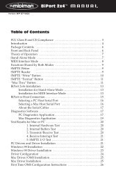
1 Instrument Inputs (Channels 1/2): These unbalanced 1/4” jacks are used for connecting high impedance<br />
instrument-level signals (i e , electric guitars and basses) to <strong>ProFire</strong> <strong>2626</strong> When using these inputs, make sure that<br />
the Mic/Inst (2) button is set to its “in” position in<br />
order to route the associated instrument input to<br />
the preamp<br />
2 Mic/Inst Buttons: These buttons determine<br />
whether the channel’s XLR input (rear-panel<br />
combo jack) or the 1/4” instrument input (on the<br />
front panel) will be routed to the preamp When<br />
this button is set to the “out” position, the combo<br />
jack’s XLR connection will be active and the front<br />
panel input will be ignored Conversely, when this<br />
button is set to the “in” position, the channel’s<br />
1/4” front panel input will be active and the combo<br />
jack’s XLR connection will be ignored<br />
3<br />
3 Signal/Clip Indicators: The green LED indicates<br />
the presence of a signal at the corresponding analog<br />
input while the red LED indicates “clipping” or<br />
distortion at the input Use these LED meters to set<br />
levels for the eight analog inputs<br />
4 Gain Adjustment Knobs / 20dB Pads: These<br />
are dual function knobs that are used to adjust the<br />
preamp gain as well as to engage a 20dB pad Turn<br />
this knob clockwise to increase the input gain for a<br />
channel Pull the knob to the “out” position to engage<br />
a 20dB pad or leave the knob in the “in” position to<br />
allow signals to bypass the pad<br />
4<br />
3<br />
4<br />
3<br />
4<br />
3<br />
4<br />
3 3 3<br />
4 4 4<br />
5<br />
6<br />
7<br />
6<br />
NOTE: The 1/4” line input section of the combo<br />
connector (on the rear of the interface) is never sent to<br />
the preamp, however, the interface does sum the 1/4”<br />
line-level portion of the combo jack and front-panel<br />
instrument-level input. While the summing of these two<br />
1/4” inputs does not affect either input’s impedance or<br />
signal level, it does make it possible to record audio<br />
from both inputs simultaneously. If you have connected<br />
a line-level device to the rear of the interface but only<br />
intend to record from the corresponding instrument<br />
input on the front, please make sure that the connected<br />
device is not outputting any audio (or is powered off).<br />
Setting Gain Levels<br />
To set gain levels for an analog input, begin by turning<br />
the Gain Adjustment Knob (4) for that channel fully<br />
counter-clockwise. While the sound source is playing at<br />
its loudest levels, slowly turn the knob clockwise until the<br />
red clip indicator (3) begins to illuminate. Then, turn the<br />
knob counter-clockwise until the clip indicator no longer<br />
illuminates. At this point, you should be ready to record with<br />
the optimum gain setting.<br />
Please keep in mind that the red LED indicates that your<br />
input is clipping (distorting) digitally. This is not the same<br />
kind of analog-style distortion found on guitar amplifiers and<br />
stomp boxes. Digital distortion is generally considered to be<br />
harsh and unmusical and it is recommended that you use<br />
these LED meters to avoid this type of clipping.<br />
7<br />
8<br />
9<br />
10
<strong>ProFire</strong> <strong>2626</strong><br />
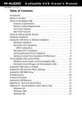
5 Phantom Power Buttons: These two buttons apply<br />
+48V phantom power to XLR inputs 1-4 and 5-8 The top<br />
button activates phantom power on XLR inputs 1 through<br />
4 while the bottom button activates phantom power for<br />
inputs 5 through 8 The LED next to each button will<br />
illuminate when phantom power is being sent to the<br />
associated channels<br />
6 Headphone Level Knobs: These knobs adjust the<br />
output volume of the headphone outputs Turn these<br />
knobs clockwise to increase the level of their associated<br />
headphone outputs; turn them counterclockwise to reduce<br />
the output levels<br />
<strong>User</strong> <strong>Guide</strong> 7<br />
7 Headphone Jacks: Connect headphones to these jacks The first headphone output is sourced from audio routed<br />
to analog outputs 1/2 while the second headphone output is sourced from audio routed to analog outputs 3/4<br />
8 Master Volume Knob: This knob controls the<br />
analog output levels of <strong>ProFire</strong> <strong>2626</strong> Turning the knob<br />
clockwise will increase the output level while turning<br />
it counterclockwise will reduce the output level By<br />
default, this knob is assigned to control analog outputs<br />
1/2, however, the Control Panel application provides<br />
the option of setting the Master Volume knob to control<br />
any combination of analog output pairs (i e , 1/2, 3/4,<br />
5/6, or 7/8) This includes the ability to control the level<br />
of all eight analog outputs simultaneously This feature<br />
has been implemented to facilitate many kinds of stereo<br />
and surround mixing scenarios<br />
See the Control Panel section of this <strong>User</strong> <strong>Guide</strong> for<br />
more information about how to configure and use the<br />
Master Volume knob<br />
9 Power Button: This button turns the <strong>ProFire</strong> <strong>2626</strong><br />
interface on and off Make sure to connect the FireWire<br />
cable to your computer before turning on the interface<br />
Hot-plugging (i e , connecting the FireWire cable while<br />
the interface is powered on) may have adverse effects<br />
on your <strong>ProFire</strong> <strong>2626</strong> and/or your computer Please<br />
refer to the M-<strong>Audio</strong> knowledge base at www m-audio<br />
com for additional information about hot-plugging<br />
About Phantom Power:<br />
Be mindful when engaging phantom power<br />
since not all microphones require phantom<br />
power to operate. For example, most dynamic<br />
microphones do not require any phantom power<br />
whereas condenser microphones usually do.<br />
Some vintage ribbon microphones may be<br />
damaged if phantom power is applied to them.<br />
Always consult your microphone’s manual<br />
before applying phantom power.<br />
HINT: To control the level of the main monitor<br />
mix without affecting the level at the headphone<br />
outputs, assign the Master Volume knob to<br />
either analog outputs 5/6 or 7/8 and use those<br />
outputs for your main monitors. This prevents the<br />
Master Volume Knob from influencing the levels<br />
of headphone outputs 1 and 2 and effectively<br />
provides front panel volume controls for three<br />
unique stereo outputs.<br />
If you already have a way of controlling the<br />
main monitor mix level (e.g. through the use<br />
of an external mixer), another good use for the<br />
assignable Master Volume Knob is as an auxiliary<br />
send. Simply connect one of the analog output<br />
pairs to an outboard effects unit and assign the<br />
Master Volume Knob to the respective channels.<br />
Bring the outboard effect’s outputs back into the<br />
<strong>ProFire</strong> <strong>2626</strong> interface using any two available<br />
audio inputs as the auxiliary return and use the<br />
Master Volume Knob to control the auxiliary send<br />
level.<br />
10 Power Indicator: This LED illuminates when the interface is powered on It remains continuously lit when the<br />
unit is receiving power and a valid digital clock signal (internal or external); the LED blinks when the interface is not<br />
synchronizing properly to digital clock
<strong>ProFire</strong> <strong>2626</strong><br />
6<br />
Architecture of <strong>ProFire</strong> <strong>2626</strong><br />
<strong>User</strong> <strong>Guide</strong> 9<br />
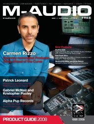
<strong>ProFire</strong> <strong>2626</strong> is much more than a simple audio input and output device Its high quality signal path, DSP mixer, and<br />
flexible router allow the interface to become the central nervous system of your studio The block diagram below<br />
illustrates audio signal flow within <strong>ProFire</strong> <strong>2626</strong> and demonstrates the relationship between various components within<br />
the interface (each of the blocks in the diagram are described in detail further below):<br />
Hardware Inputs<br />
Analog ADAT A ADAT B S/PDIF<br />
1|2|3|4|5|6|7|8 1|2|3|4|5|6|7|8 1|2|3|4|5|6|7|8 1|2<br />
44.1/48kHz Operation (Mac & PC)<br />
Mac /PC<br />
<strong>Audio</strong> Application<br />
18x16<br />
DSP Mixer<br />
Router<br />
(Select source for each hardware output)<br />
1|2|3|4|5|6|7|8 1|2|3|4|5|6|7|8 1|2|3|4|5|6|7|8 1|2<br />
Analog ADAT A ADAT B S/PDIF<br />
Hardware Outputs<br />
Software Returns<br />
1|2|3|4|5|6|7|8|9|10|11|12|13|14|15|16|17|18|19|20|21|22|23|24|25|26<br />
Hardware Inputs – These are the physical audio inputs on <strong>ProFire</strong> <strong>2626</strong> including the eight analog combo jacks, two<br />
instrument inputs, two ADAT ports, and the S/PDIF connector All signals that enter the interface through the hardware<br />
inputs can be sent to the Mac/PC, DSP Mixer, and Router (all described below)<br />
Mac/PC – This block represents your computer and its DAW software All signals received at the hardware inputs can<br />
be sent to your computer and made available for recording and mixing within the audio application
<strong>ProFire</strong> <strong>2626</strong><br />
Software Returns – This block represents the audio<br />
outputs of your audio application Software returns<br />
can be routed to the DSP Mixer and the Router (both<br />
described below)<br />
DSP Mixer – This is the 18 input, 16 output DSP<br />
mixer contained within the <strong>ProFire</strong> <strong>2626</strong> interface<br />
The block features a dashed line because the DSP<br />
mixer can be completely bypassed by the user if<br />
desired<br />
As shown in the illustration above, the mixer’s 18 input<br />
channels accept signals from any of the hardware<br />
inputs or software returns See the “Mixer” section of<br />
the “Control Panel Application” chapter to learn how<br />
to configure and use the DSP mixer<br />
In cases where the computer is unable to run with<br />
sufficiently small buffer size settings (i e , the software<br />
monitoring latency is too high), the DSP Mixer can be<br />
used instead to achieve near-zero latency monitoring<br />
of your input signals<br />
Router – The Router is a device that lets you select<br />
the source of each hardware output on <strong>ProFire</strong> <strong>2626</strong><br />
These sources include any pair of hardware inputs,<br />
the main output of the DSP mixer or any of its seven<br />
auxiliary sends, and any available software return pair<br />
The router is an extremely useful tool since it allows<br />
you to reconfigure how audio streams flow out of the<br />
interface without having to physically re-patch the<br />
cables connected to the back of the interface<br />
Hardware Outputs – These are the physical outputs<br />
of <strong>ProFire</strong> <strong>2626</strong> including the eight 1/4” analog jacks,<br />
two ADAT ports, and the S/PDIF connector The<br />
Router (see above) lets you select the source of each<br />
hardware output pair<br />
About Software Returns:<br />
<strong>User</strong> <strong>Guide</strong> 10<br />
The term “Return” has its roots in analog recording,<br />
where input sources (Microphones, Instruments, etc.)<br />
are connected to large format mixing consoles, routed<br />
to multi-track reel-to-reel tape machines for recording<br />
and then returned to the mixing desk. This allows the<br />
recording engineer to hear the recorded signal from tape<br />
while the recording is still in process. This way, problems<br />
with the recording (e.g. tape imperfections, or distorting<br />
signals) can be detected in real-time.<br />
While recording systems have evolved greatly over the<br />
years and DAW applications have become more popular<br />
for recording and playback, the concept of returning<br />
signals from your recording device has not changed. In<br />
the case of the <strong>ProFire</strong> <strong>2626</strong>, the output of your audio<br />
software (the recording device) is returned to the <strong>ProFire</strong><br />
<strong>2626</strong> Router section – hence the term “software returns.”<br />
Signals returning from your software to <strong>ProFire</strong> <strong>2626</strong><br />
can then be sent to the DSP mixer and/or any hardware<br />
output of your choosing.<br />
Why use the DSP Mixer?<br />
Most audio applications include mixing and monitoring<br />
functionality and you may be wondering why you<br />
would want to use the <strong>ProFire</strong> <strong>2626</strong> DSP Mixer for<br />
monitoring instead of the DAW application. The main<br />
reason for using the DSP Mixer is that software-based<br />
audio applications suffer from a phenomenon known<br />
as “latency.” Latency is the amount of time it takes your<br />
audio signals to pass through the computer (and its DAW<br />
software) and become available at the hardware outputs.<br />
This delay is usually quite small and is measured in<br />
milliseconds, but it may be large enough to distract a<br />
performer who wishes to record while monitoring through<br />
software.<br />
The amount of latency varies depending on many factors<br />
including your computer’s performance and buffer size<br />
settings. Powerful computers with fast processors may<br />
allow you to run your sessions with very small buffer size<br />
settings, providing virtually imperceptible latency. In this<br />
case, you can use your application’s software monitoring<br />
features and bypass the <strong>ProFire</strong> <strong>2626</strong> DSP Mixer.
<strong>ProFire</strong> <strong>2626</strong><br />
<strong>ProFire</strong> <strong>2626</strong> Operation at High Sample Rates<br />
<strong>User</strong> <strong>Guide</strong> 11<br />
<strong>ProFire</strong> <strong>2626</strong> can operate at high sample rates including 88 2/96 kHz and 176 4/192 kHz However, the number of<br />
available inputs and outputs is reduced when operating at these rates and certain input and output ports are disabled as<br />
a result (see the “About S/MUX II and S/MUX IV modes” section for additional information) Furthermore, at high sample<br />
rates, the number of software returns is automatically reduced to match the number of available hardware outputs and to<br />
preserve system resources This section describes how channels are affected at high sample rates<br />
Note that since Windows and OS X operating systems handle audio differently, each operating system is described<br />
separately<br />
About S/MUX II and S/MUX IV modes:<br />
An ADAT port is designed to transfer eight channels of audio at sample rates up to 48 kHz When operating at higher<br />
sample rates, the port must operate in S/MUX II (up to 96 kHz) or S/MUX IV (up to 192 kHz) mode S/MUX II mode<br />
combines pairs of ADAT channels (i e channels 1/2→1, 3/4→2, 5/6→3, 7/8→4) to create four high bandwidth channels<br />
capable of transferring high resolution audio up to 96 kHz S/MUX IV mode combines groups of four ADAT channels<br />
(i e , 1-4→1, 5-8→2) to create two high bandwidth channels capable of transferring high resolution audio up to 192 kHz<br />
Sample Rate Number of Channels<br />
44 1-48 kHz 8<br />
(per ADAT port)<br />
88 2-96 kHz 4 (S/MUX II)<br />
176 4-192 kHz 2 (S/MUX IV)
<strong>ProFire</strong> <strong>2626</strong><br />
MAC OS X: 88.2/96 kHz Operation<br />
88.2/96 kHz Operation (Mac)<br />
Hardware Inputs<br />
Analog ADAT A (S/MUX II) ADAT B (S/MUX II) S/PDIF<br />
1|2|3|4|5|6|7|8 1|2|3|4|5|6|7|8 1|2|3|4|5|6|7|8 1|2<br />
Mac<br />
<strong>Audio</strong> Application<br />
18x16<br />
DSP Mixer<br />
Router<br />
(Select source for each hardware output)<br />
1|2|3|4|5|6|7|8 1|2|3|4|5|6|7|8| 1|2|3|4|5|6|7|8| 1|2<br />
Analog ADAT A (S/MUX II) ADAT B (S/MUX II) S/PDIF<br />
Hardware Outputs<br />
Software Returns<br />
<strong>User</strong> <strong>Guide</strong> 12<br />
1|2|3|4|5|6|7|8|9|10|11|12|13|14|15|16|17|18|19|20|21|22|23|24|25|26<br />
At sample rates of 88 2 or 96 kHz, the ADAT ports operate in S/MUX II mode As a result, the number of available ADAT<br />
channels is reduced to four channels per port (i e , channels 5-8 are disabled on all ADAT I/O ports) and software return<br />
channels 19-26 are disabled<br />
Tip: <strong>User</strong>s who regularly work at different sample rates may wish to use the Control Panel’s “save” and<br />
“load” functions to store and recall preferred routing assignments for each sample rate. This will allow them to<br />
quickly shift between various sample rates without having to reconfigure routing assignments each time.
<strong>ProFire</strong> <strong>2626</strong><br />
MAC OS X: 176.4/192 kHz Operation<br />
176.4/192 kHz Operation (Mac)<br />
Hardware Inputs<br />
ADAT A<br />
ADAT B<br />
Analog (S/MUX IV) (S/MUX IV) S/PDIF<br />
1|2|3|4|5|6|7|8 1|2|3|4|5|6|7|8 1|2|3|4|5|6|7|8 1|2<br />
18x16<br />
DSP Mixer<br />
Router<br />
(Select source for each hardware output)<br />
1|2|3|4|5|6|7|8 1|2|3|4|5|6|7|8| 1|2|3|4|5|6|7|8| 1|2<br />
Analog<br />
ADAT A<br />
(S/MUX IV)<br />
Mac<br />
<strong>Audio</strong> Application<br />
ADAT B<br />
(S/MUX IV)<br />
Hardware Outputs<br />
S/PDIF<br />
<strong>User</strong> <strong>Guide</strong> 13<br />
Software Returns<br />
1|2|3|4|5|6|7|8|9|10|11|12|13|14|15|16|17|18|19|20|21|22|23|24|25|26<br />
At sample rates of 176 4 or 192 kHz, the ADAT ports operate in S/MUX IV mode As a result, the number of available<br />
ADAT channels is reduced to two channels per port (i e , channels 3-8 are disabled on all ADAT I/O ports), and software<br />
return channels 15-26 are disabled<br />
Tip: <strong>User</strong>s who regularly work at different sample rates may wish to use the Control Panel’s “save” and “load”<br />
functions to store and recall preferred routing assignments for each sample rate. This will allow them to quickly<br />
shift between various sample rates without having to reconfigure routing assignments each time.
<strong>ProFire</strong> <strong>2626</strong><br />
Windows XP/Vista: 88.2/96 kHz Operation<br />
88.2/96 kHz Operation (PC)<br />
Hardware Inputs<br />
Analog ADAT A (S/MUX II) ADAT B (S/MUX II) S/PDIF<br />
1|2|3|4|5|6|7|8 1|2|3|4|5|6|7|8 1|2|3|4|5|6|7|8 1|2<br />
PC<br />
<strong>Audio</strong> Application<br />
18x16<br />
DSP Mixer<br />
Router<br />
(Select source for each hardware output)<br />
1|2|3|4|5|6|7|8 1|2|3|4|5|6|7|8| 1|2|3|4|5|6|7|8| 1|2<br />
Analog ADAT A (S/MUX II) ADAT B (S/MUX II) S/PDIF<br />
Hardware Outputs<br />
<strong>User</strong> <strong>Guide</strong> 14<br />
Software Returns<br />
1|2|3|4|5|6|7|8|9|10|11|12|13|14|15|16|17|18|19|20|21|22|23|24|25|26<br />
At sample rates of 88 2 or 96 kHz, the ADAT ports operate in S/MUX II mode As a result, the number of available ADAT<br />
channels is reduced to four channels per port (i e , channels 5-8 are disabled on all ADAT I/O ports) and software return<br />
channels 13-16 and 21-24 are disabled<br />
TIP: <strong>User</strong>s who regularly work at different sample rates may wish to use the Control Panel’s “save” and “load”<br />
functions to store and recall preferred routing assignments for each sample rate. This will allow them to quickly<br />
shift between various sample rates without having to reconfigure routing assignments each time.<br />
Windows XP/Vista <strong>User</strong>s:<br />
Please note that certain input and output ports become unavailable at high resolutions (such as ADAT 5-8 in<br />
S/MUX II mode). While the ports will become disabled as the sample rate is increased, your DAW application’s<br />
audio inputs and outputs may still be routed to unavailable ports. In this case, the disabled inputs and outputs will<br />
not stream audio.<br />
To avoid this, configure your DAW application’s inputs to receive audio from active ports and make sure that<br />
the application is sending audio to active software returns. Next, you may need to reconfigure the Router to<br />
ensure that the software returns from your DAW application are routed to active hardware output ports. To help<br />
you quickly identify disabled hardware inputs and software returns, the Control Panel application grays-out and<br />
italicizes any inputs, outputs, or software returns that are disabled. The DSP Mixer displays an exclamation<br />
point ( ) if the input source stream has become disabled.
<strong>ProFire</strong> <strong>2626</strong><br />
Windows XP/Vista: 176.4/192 kHz kHz Operation Operation (PC)<br />
Hardware Inputs<br />
ADAT A<br />
ADAT B<br />
Analog (S/MUX IV) (S/MUX IV) S/PDIF<br />
1|2|3|4|5|6|7|8 1|2|3|4|5|6|7|8 1|2|3|4|5|6|7|8 1|2<br />
18x16<br />
DSP Mixer<br />
Router<br />
(Select source for each hardware output)<br />
1|2|3|4|5|6|7|8 1|2|3|4|5|6|7|8 1|2|3|4|5|6|7|8 1|2<br />
Analog ADAT A<br />
(S/MUX IV)<br />
PC<br />
<strong>Audio</strong> Application<br />
ADAT B<br />
(S/MUX IV)<br />
Hardware Outputs<br />
S/PDIF<br />
<strong>User</strong> <strong>Guide</strong> 15<br />
Software Returns<br />
1|2|3|4|5|6|7|8|9|10|11|12|13|14|15|16|17|18|19|20|21|22|23|24|25|26<br />
At sample rates of 176 4 or 192 kHz, the ADAT ports operate in S/MUX IV mode As a result, the number of available<br />
ADAT channels is reduced to two channels per port (i e , channels 3-8 are disabled on all ADAT I/O ports), and software<br />
return channels 11-16 and 19-24 are disabled<br />
TIP: <strong>User</strong>s who regularly work at different sample rates may wish to use the Control Panel’s “save” and “load”<br />
functions to store and recall preferred routing assignments for each sample rate. This will allow them to quickly<br />
shift between various sample rates without having to reconfigure routing assignments each time.<br />
Windows XP/Vista <strong>User</strong>s:<br />
Please note that certain input and output ports become unavailable at high resolutions (such as ADAT 5-8 in<br />
S/MUX II mode). While the ports will become disabled as the sample rate is increased, your DAW application’s<br />
audio inputs and outputs may still be routed to unavailable ports. In this case, the disabled inputs and outputs will<br />
not stream audio.<br />
To avoid this, configure your DAW application’s inputs to receive audio from active ports and make sure that<br />
the application is sending audio to active software returns. Next, you may need to reconfigure the Router to<br />
ensure that the software returns from your DAW application are routed to active hardware output ports. To help<br />
you quickly identify disabled hardware inputs and software returns, the Control Panel application grays-out and<br />
italicizes any inputs, outputs, or software returns that are disabled. The DSP Mixer displays an exclamation<br />
point ( ) if the input source stream has become disabled.
<strong>ProFire</strong> <strong>2626</strong><br />
7<br />
Control Panel Application<br />
<strong>User</strong> <strong>Guide</strong> 16<br />
<strong>ProFire</strong> <strong>2626</strong> provides adjustable parameters for many of its features Some of them can be accessed directly from<br />
the <strong>ProFire</strong> <strong>2626</strong> front panel, such as input gain, phantom power, and output levels However, there are additional<br />
parameters that cannot be accessed from the front panel—these will be available to you using the included Control Panel<br />
software<br />
In Windows, open the <strong>ProFire</strong> <strong>2626</strong> control panel by double-clicking on the M-<strong>Audio</strong> icon in the system tray, or from<br />
Start > Control Panel (Classic View)<br />
In Mac OS X, click the M-<strong>Audio</strong> <strong>ProFire</strong> <strong>2626</strong> icon in the system preferences window<br />
The Control Panel features four tabs across the top of the screen (shown below) Each tab focuses on a specific<br />
component or feature set of <strong>ProFire</strong> <strong>2626</strong> and is described below<br />
Mixer<br />
The tab labeled “Mixer,” provides access to the <strong>ProFire</strong> <strong>2626</strong> DSP Mixer This 18-input, 16-output mixer allows you<br />
create up to eight different stereo mixes from 18 input sources consisting of any of the hardware inputs (i e , analog and<br />
digital inputs) and software returns (software outputs) This allows you to set up near-zero latency cue mixes in which the<br />
perfomers hear “customized” mixes while recording The “Example Scenario #1” section in this user guide describes a<br />
real-world scenario in which the DSP Mixer can be used and provides a detailed tutorial on how to set up and use<br />
the mixer
<strong>ProFire</strong> <strong>2626</strong><br />
<strong>User</strong> <strong>Guide</strong> 17<br />
It is important to note that any changes made to the DSP Mixer will only affect what is audible from the mixer’s<br />
outputs—the DSP Mixer does not affect the signals that are sent to the audio application for recording For example,<br />
if you are recording a vocalist and he/she tells you to turn up the vocal track so they can hear themselves better, you<br />
can increase the vocalist’s microphone channel in the DSP Mixer This will make the vocal part louder in the vocalist’s<br />
headphones, but it will still be recorded into the audio application at the volume determined by the front panel Gain<br />
Adjustment Knob (4)<br />
The DSP Mixer is set up like a standard mixing console: There are 18 input channels, each with its own volume fader, pan<br />
and aux send knobs, solo ( ), and mute ( ) buttons, as well as a master output section with its own pair of faders,<br />
and mute buttons<br />
A pair of channels can be linked together by clicking the link icon ( )<br />
between the two channels Linking channels allows you to adjust mute, solo,<br />
aux, and fader settings simultaneously by modifying parameters on either one<br />
of the linked channels<br />
The DSP mixer features multi-segment meters to show input channel levels<br />
(directly above each channel) and main mixer output levels (at the top right of the mixer) The peak hold indication time as<br />
well as pre/post fader metering operation can be set from the Settings tab of the Control Panel Finally, the clip indicators<br />
can be reset by clicking on the meter itself<br />
The signal source for each of the DSP Mixer’s 18 input channels can be selected from 52 possible signal streams<br />
(26 input streams and 26 software return streams) Click the downward arrow ( ) and make a selection from the<br />
drop-down menu that appears If an exclamation point ( ) is displayed in place of a downward arrow, the currently<br />
selected stream is disabled because of S/MUX operation or by user preference Grayed out and italicized drop-down<br />
selections are also disabled and will not stream audio<br />
if selected To resolve this issue, select another input<br />
source that is not deactivated, reduce the sample rate<br />
of the interface, or increase the number of active input<br />
ports or software returns if possible (the reduction of<br />
input ports and software returns is covered in detail in<br />
the “Why are channels disabled?” text box on the next<br />
page<br />
As stated earlier, setting or adjusting the DSP Mixer<br />
will not affect the signal that is recorded into the audio<br />
application For example, you’ll still be able to record<br />
a channel while its corresponding DSP Mixer channel<br />
is muted You won’t hear the part through the DSP<br />
mixer as it is being recorded, but it will still record into<br />
your audio application and play back properly<br />
Useful Tips and Shortcuts:<br />
NOTE: Linking two channels will<br />
not have any effect on their pan<br />
or channel input selection. These<br />
settings are always made on a<br />
per-channel basis.<br />
<strong>•</strong> The input channel numbers (listed along the bottom<br />
of the mixer) can be renamed by clicking on them. For<br />
example, if a bass guitar is routed to input channel 8, you<br />
can click the “8” at the bottom and rename the channel to<br />
“Bass.” Note that changing a channel name only affects<br />
the labeling in the DSP Mixer and does not affect the<br />
way that input appears in your computer’s audio software.<br />
<strong>•</strong> By alt-clicking (option-click for Mac users) the mute,<br />
solo, or link buttons, you can quickly mute, solo, or link<br />
all of the DSP Mixer’s 18 input channels at once. This is<br />
also a handy feature in situations where you have muted/<br />
soloed/linked multiple channels and need to quickly<br />
unmute/unsolo/unlink them. Note that the mute buttons<br />
for the input channels (just above the faders) and the<br />
mute buttons for the aux sends (on the right side of the<br />
mixer) operate independently of each other.<br />
<strong>•</strong> A fader or aux send knob can be set to unity gain by<br />
either double-clicking or alt-clicking it (option-click for<br />
Mac users).
<strong>ProFire</strong> <strong>2626</strong><br />
Why are software returns disabled?<br />
<strong>User</strong> <strong>Guide</strong> 18<br />
When the interface operates at higher sample rates (i.e., 88.2/96 kHz or 176.4/192 kHz), certain hardware<br />
input and output ports become disabled due to S/MUX II and S/MUX IV operation. When this happens, the<br />
Control Panel automatically scales the number of software return channels to match the number of hardware<br />
outputs. See the section entitled “Architecture of <strong>ProFire</strong> <strong>2626</strong>” to learn about which specific hardware I/O and<br />
software return channels become disabled at various sample rates.<br />
NOTE: If you wish to use the DSP Mixer of <strong>ProFire</strong> <strong>2626</strong> for input monitoring, be sure to mute your DAW<br />
application’s recording channels (or, if possible, turn off the application’s monitor mixing functionality altogether)<br />
to prevent two separate cue mixes from being created (this can cause undesirable effects such as phasing and<br />
slap-back delays). Conversely, if you wish to use your application’s own monitor mixing capabilities, you will<br />
most likely want to bypass the <strong>ProFire</strong> <strong>2626</strong> DSP Mixer to prevent “double-monitoring” from taking place.<br />
The DSP Mixer can be bypassed by either muting all of its input channels or by making sure that the Mixer’s<br />
outputs are not routed to any hardware outputs in the Router (see the following section to learn more about the<br />
Router).<br />
Keep in mind that that the DSP Mixer channels have up to seven auxiliary sends* that can be shown or hidden using the<br />
“+” and “–“ buttons ( ) on the right side of the mixer Hiding an aux send channel does not disable the channel but<br />
simply allows the row of aux sends to be hidden to minimize the size of the Control Panel Each row of auxiliary sends also<br />
has its own mute ( ) button allowing you to quickly silence the mix created by its associated row of aux send knobs<br />
Aux sends can be routed to any of the hardware outputs on the interface via the Router tab and can be used to send<br />
signals to external effects processors just like an Aux Send on a traditional mixing console Another common use of<br />
this functionality is to create custom cue mixes for separate performers (this topic is covered in “Example Scenario #1”<br />
section of this guide) The aux sends are in stereo and will always maintain the pan settings made in the DSP Mixer<br />
channels<br />
* When operating at 176.4 or 192 kHz sample rates, the number of available auxiliary sends is reduced to one.
<strong>ProFire</strong> <strong>2626</strong><br />
Router<br />
The <strong>ProFire</strong> <strong>2626</strong> Router tab contains a variety of parameters affecting how audio is<br />
routed through the interface These parameters are grouped into categories as<br />
explained on the following pages<br />
<strong>User</strong> <strong>Guide</strong> 19<br />
Active Software Returns<br />
configuration options for<br />
Windows users.
<strong>ProFire</strong> <strong>2626</strong><br />
Output Source Routing<br />
This section lets you select the audio source for<br />
each hardware output pair on the interface<br />
The Router has four columns of drop down menus:<br />
These columns (from left to right) represent the<br />
Analog Outputs, the first set of ADAT Outputs, the<br />
second set of ADAT outputs, and finally the the<br />
coaxial S/PDIF output<br />
To use the Router, first locate the pair of hardware<br />
outputs to which you’d like to send audio Next,<br />
click the downward arrow to open the drop-down<br />
menu and select the audio source you’d like to<br />
connect to your chosen output <strong>ProFire</strong> <strong>2626</strong> will<br />
now route that audio source to your selected output<br />
In the drop-down menu, the analog, ADAT, and<br />
S/PDIF inputs correspond to the analog, ADAT and<br />
S/PDIF hardware inputs found on the interface The<br />
“SW Return” selections correspond to the outputs<br />
<strong>User</strong> <strong>Guide</strong> 20<br />
of your audio software, while the “Aux Send” selections correspond to the stereo Auxiliary Send outputs of the<br />
DSP Mixer described in the previous section “Mixer Out” is the master output of the <strong>ProFire</strong> <strong>2626</strong> DSP Mixer<br />
Note that if any of the drop-down selections appear grayed-out and italicized, this means that the stream is inactive<br />
(see the “Why are hardware inputs and outputs disabled?” box on this page for additional information) Select<br />
a stream that is not italicized or grayed-out from the drop down menu to route an active stream to your chosen<br />
output<br />
Active Input Ports<br />
These checkboxes determine which groups of hardware inputs are currently active on the interface If a box is<br />
checked, its corresponding inputs are active; if a box is left unchecked, the corresponding ports are not active and<br />
the audio software will not receive any signal from this input until it is made active again Be sure to deactivate<br />
any ports that are not being used as this will reduce the demands placed on the FireWire bus and decrease<br />
the amount of system resources used by <strong>ProFire</strong> <strong>2626</strong> Deactivated inputs and outputs will be grayed-out and<br />
italicized in the Control Panel<br />
Note that at least one group of inputs must be active; the Control<br />
Panel will not allow you to disable any more than three of the four<br />
available check boxes<br />
Windows users: Note that inputs and outputs will always appear<br />
in your audio software, regardless of how these checkboxes are<br />
set However, signals associated with deactivated ports will not be<br />
received by the software<br />
Why are hardware inputs and<br />
outputs disabled?<br />
When the interface operates at higher sample<br />
rates (i.e., 88.2/96 kHz or 176.4/192 kHz), certain<br />
hardware input and output ports become disabled<br />
due to the design of the S/MUX II and S/MUX IV<br />
protocols. When this happens, the Control Panel<br />
automatically scales back the number of software<br />
return channels to match the number of hardware<br />
outputs.<br />
Additionally, you can choose to disable unused<br />
hardware input ports and/or software return channels<br />
to minimize the amount of system resources used by<br />
<strong>ProFire</strong> <strong>2626</strong>. Both of these occurrences may result<br />
in Router output sources appearing grayed-out and<br />
italicized.<br />
NOTE: <strong>Audio</strong> signals received<br />
at disabled input ports are not<br />
transmitted to the computer through<br />
the FireWire cable. However, signals<br />
present at the hardware inputs are<br />
always audible through the DSP<br />
Mixer/Router even if its corresponding<br />
ports have been disabled in the<br />
Router. Furthermore, the interface can<br />
still receive digital clocking information<br />
through the S/PDIF or ADAT ports<br />
even if they have been disabled from<br />
this menu.
<strong>ProFire</strong> <strong>2626</strong><br />
Settings<br />
The Settings tab contains several parameters that govern the<br />
operation of <strong>ProFire</strong> <strong>2626</strong> These options are grouped in the<br />
following categories:<br />
<strong>User</strong> <strong>Guide</strong> 22<br />
Windows only:<br />
Buffer Size drop-down menu.
<strong>ProFire</strong> <strong>2626</strong><br />
<strong>User</strong> <strong>Guide</strong> 23<br />
Hosted Mode<br />
The parameters in this section of the Control Panel govern the operation of the interface when it is connected<br />
to a computer using a FireWire cable (i e , Hosted Mode)<br />
Sync Source<br />
This drop-down menu determines the clock source to which <strong>ProFire</strong> <strong>2626</strong> is synchronized If you are using<br />
<strong>ProFire</strong> <strong>2626</strong> by itself (i e , without other digital devices or an external clock), this parameter must be set to<br />
“Internal” for the interface to work properly<br />
If you have connected a S/PDIF, ADAT, or Word Clock device to your <strong>ProFire</strong> <strong>2626</strong> and would like to use that<br />
device’s clock as the master clock source, select “ADAT A,” “ADAT B,” “Coax S/PDIF,” or “Word Clock” from<br />
this drop down menu This will make <strong>ProFire</strong> <strong>2626</strong> lock to the external device’s clock<br />
About Clock:<br />
If you are using <strong>ProFire</strong> <strong>2626</strong> in conjunction with other digital devices in<br />
your studio, you will need to designate one device in your studio as the<br />
“clock master.” All other digital devices must be set to lock (or “slave”) to<br />
the master device’s clock.<br />
For example, if you have connected your <strong>ProFire</strong> <strong>2626</strong> and a DAT<br />
recorder using a pair of S/PDIF cables (i.e., the S/PDIF output of <strong>ProFire</strong><br />
<strong>2626</strong> has been connected to the S/PDIF input of the DAT recorder;<br />
the S/PDIF output of the DAT has been connected to the S/PDIF input<br />
on <strong>ProFire</strong> <strong>2626</strong>), you must configure either <strong>ProFire</strong> <strong>2626</strong> or the DAT<br />
recorder to act as the clock master, while the other device must be set to<br />
“external” or “slave” mode. If your devices are not configured in this way,<br />
you may hear clicks, pops, and other unwanted glitches in your audio.<br />
If you wish to set <strong>ProFire</strong> <strong>2626</strong> as the master, set the “Sync Source”<br />
parameter in the Control Panel to “Internal.” If you would like <strong>ProFire</strong><br />
<strong>2626</strong> to lock to another device connected using ADAT, S/PDIF, or Word<br />
Clock, select “ADAT A,” “ADAT B,” “Coax S/PDIF,” or “Word Clock”<br />
from the drop-down menu. In this scenario, you’ll need to ensure that<br />
the external device is set as the clock master.<br />
Refer to the “Digital Clocking” section of this guide to learn more about<br />
clocking and to learn how to digitally synchronize multiple digital devices<br />
to one clock.
<strong>ProFire</strong> <strong>2626</strong><br />
Optical Port B Mode<br />
<strong>User</strong> <strong>Guide</strong> 25<br />
This portion of the Control Panel determines how the second pair of optical ports on the rear of the interface<br />
will operate Setting this parameter to “ADAT” will allow <strong>ProFire</strong> <strong>2626</strong> to receive or send 16 channels of<br />
44 1/48kHz signals, eight channels of 88 2/96 kHz signals, or four channels of 176 4/192 kHz signals by<br />
using both optical ports in tandem<br />
Selecting “S/PDIF” will allow the second optical input and output ports to receive and send stereo S/PDIF<br />
signals Note that optical S/PDIF operates at a maximum sample rate of 96 kHz<br />
S/MUX Mode<br />
Each ADAT optical cable can carry eight channels of audio when operating at standard sample rates of 44 1<br />
or 48 kHz, four channels when operating at sample rates of 88 2 or 96 kHz (S/MUX II Mode), or two channels<br />
while operating at 176 4 or 192 kHz (S/MUX IV mode) These high resolution modes are known as<br />
“S/MUX II” and “S/MUX IV” and are enabled when an ADAT source toggles a special bit in its output stream<br />
This bit tells the destination device to switch to the proper S/MUX mode in order to receive the high resolution<br />
signal correctly<br />
Unfortunately, some devices that are capable of S/MUX II or S/MUX IV operation do not set the S/MUX bit<br />
correctly and, as a result, the <strong>ProFire</strong> <strong>2626</strong> may be unable to automatically detect the desired sample rate The<br />
“S/MUX Mode” option resolves this issue:<br />
Auto– This is the default setting and should work in most cases When this mode is selected,<br />
<strong>ProFire</strong> <strong>2626</strong> observes the S/MUX bit of an incoming signal and automatically switches between standard,<br />
S/MUX II, and S/MUX IV modes<br />
S/MUX II (88.2-96 kHz) – This parameter sets the ADAT input ports to operate in S/MUX II mode Only<br />
use this option if the default “Auto Detect” setting does not correctly recognize the sample rate of the<br />
incoming signal<br />
S/MUX IV (176.4-192 kHz) – This parameter sets the<br />
ADAT input ports to operate in S/MUX IV mode Only use<br />
this option if the default “Auto Detect” setting does not<br />
correctly recognize the sample rate of the incoming signal<br />
NOTE: This parameter only affects<br />
the ADAT inputs when the Sync<br />
Source parameter is set to “ADAT A”<br />
or “ADAT B.”
<strong>ProFire</strong> <strong>2626</strong><br />
Mixer Peak Meters<br />
This section of the Control Panel configures the operation of the meters within the DSP Mixer<br />
Mode<br />
This drop-down menu determines the behavior of the meters of the <strong>ProFire</strong> <strong>2626</strong> DSP mixer<br />
<strong>User</strong> <strong>Guide</strong> 27<br />
Pre-fader – When this parameter is set to “Pre-fader” the meters will display the level of a signal before it<br />
passes the fader This allows signal levels to be displayed regardless of the fader positions within the DSP<br />
mixer (i e , a fader can be all the way down and no sound will be heard from the mixer’s output, but you can<br />
still see if there is any activity on that input)<br />
Post-fader – This setting configures the meters to show levels after signal has passed through the faders<br />
In this configuration, fader positions will affect the meters For example, a fader that is all the way down will<br />
result in no signal being displayed on its meter<br />
Peak Hold<br />
The meters of the <strong>ProFire</strong> <strong>2626</strong> DSP mixer feature a “peak hold”<br />
function designed to assist in finding the loudest transients of<br />
a signal This drop-down menu determines how long the peak<br />
indicator will remain before resetting:<br />
Off This setting turns the peak hold function off<br />
1 Second Peak levels are held for one second<br />
3 Seconds Peak levels are held for three seconds<br />
Infinite Peak levels are held until the meters are cleared<br />
Standalone Mode<br />
<strong>ProFire</strong> <strong>2626</strong> can be used in Standalone Mode (i e , without a computer) To enter Standalone Mode, power down<br />
the interface, disconnect any FireWire cables attached to the FireWire Ports (12), and power on the interface<br />
The parameters in this section of the Control Panel determine how <strong>ProFire</strong> <strong>2626</strong> will function while operating in<br />
Standalone Mode This is a useful feature as it allows you to set the Standalone Mode settings independently from<br />
the hosted settings This saves you from having to reconfigure the Control Panel each time before you use the<br />
interface in Standalone Mode<br />
Sync Source<br />
TIP: Peak levels can be cleared at<br />
any time by clicking the meters in the<br />
DSP mixer.<br />
This drop-down menu determines the clock synchronization source when using <strong>ProFire</strong> <strong>2626</strong> in Standalone<br />
Mode<br />
If you have connected a S/PDIF, ADAT, or Word Clock device to your <strong>ProFire</strong> <strong>2626</strong> and would like to use that<br />
device’s clock as the master clock source, select “ADAT A,” “ADAT B,” “Coax S/PDIF,” or “Word Clock” from<br />
this drop down menu Otherwise, leave this parameter on its default “Internal” setting to allow <strong>ProFire</strong> <strong>2626</strong> to<br />
use its internal clock
<strong>ProFire</strong> <strong>2626</strong><br />
Sample Rate<br />
This menu selects the sample rate of the<br />
interface when operating in Standalone Mode<br />
Optical Port B Mode<br />
This parameter determines how the second pair<br />
of optical ports will operate when the interface is<br />
in Standalone mode<br />
ADAT:<br />
Selecting “ADAT” will allow you to send and<br />
receive four channels of audio at 88 2/96 kHz<br />
(per ADAT port; S/MUX II) or two channels<br />
at 176 4/192 kHz (per ADAT port; S/MUX<br />
IV) In Standalone Mode, Optical Port B can<br />
only be set to ADAT when the interface is<br />
operating at sample rates of 88 2 to 192 kHz *<br />
S/PDIF:<br />
Selecting “S/PDIF” allows the second optical<br />
input and output ports to convert optical<br />
S/PDIF signals into coaxial S/PDIF signals<br />
while simultaneously converting coaxial<br />
S/PDIF to optical S/PDIF<br />
* Since <strong>ProFire</strong> <strong>2626</strong> has a maximum of<br />
eight analog inputs and outputs, optical<br />
port B is not necessary for A/D or D/A<br />
conversions at 44.1/48 kHz. Optical port<br />
B can be used for A/D, D/A operation at<br />
sample rates above 48 kHz.<br />
<strong>User</strong> <strong>Guide</strong> 28<br />
NOTE: This parameter only displays sample<br />
rates (i.e., “44.1 kHz”, “48 kHz”, etc.) when the<br />
Standalone Mode Sync Source is set to “Internal.”<br />
If you are clocking the interface to an external S/<br />
PDIF or Word Clock device, this parameter displays<br />
“Auto” and the interface automatically locks to<br />
the sample rate of the master device. If you are<br />
clocking to an ADAT device, this menu provides<br />
the same options found under the S/MUX Mode<br />
parameter while in hosted mode (“Auto,”<br />
“S/MUX II (88.2 to 96 kHz),” and “S/MUX IV<br />
(176.4 to 192 kHz).” See the S/MUX Mode<br />
description earlier in this section to learn more<br />
about these settings.<br />
Note: The coaxial and optical S/PDIF ports support<br />
a maximum sample rate of 96 kHz when operating<br />
in Standalone mode. This is because optical S/<br />
PDIF has a maximum sample rate limit of 96<br />
kHz. As a result, when <strong>ProFire</strong> <strong>2626</strong> is operating<br />
at sample rates above 96 kHz, this parameter<br />
automatically defaults to ADAT mode.
<strong>ProFire</strong> <strong>2626</strong><br />
Converter Mode<br />
<strong>User</strong> <strong>Guide</strong> 29<br />
<strong>ProFire</strong> <strong>2626</strong> can operate in two different ways while in Standalone Mode Each mode is described separately<br />
below:<br />
A/D – D/A Mode:<br />
When this parameter is set to “A/D - D/A” mode the interface operates like a standard analog-to-digital<br />
(A/D), digital-to-analog (D/A), and S/PDIF format converter The operation of this mode varies by the<br />
sample rate of the interface This is described in detail below:<br />
44.1-48 kHz<br />
(Optical Port B can only be set to S/PDIF at these sample rates)<br />
Analog In 1-8 ADAT (port A) Out 1-8<br />
ADAT (port A) In 1-8 Analog Out 1-8<br />
Coaxial S/PDIF Optical S/PDIF<br />
Optical S/PDIF Coaxial S/PDIF<br />
88.2-96 kHz (when Optical Port B is set to ADAT)<br />
Analog In 1-8 ADAT Out 1-8*<br />
ADAT In 1-8* Analog Out 1-8<br />
88.2-96 kHz (when Optical Port B is set to S/PDIF)<br />
Analog In 1-4 ADAT Out 1-4<br />
ADAT In 1-4 Analog Out 1-4<br />
Coaxial S/PDIF Optical S/PDIF<br />
Optical S/PDIF Coaxial S/PDIF<br />
176.4-192 kHz<br />
(Optical Port B can only be set to ADAT at this sample rate)<br />
Analog In 1-4 ADAT Out 1-4**<br />
ADAT In 1-4** Analog Out 1-4<br />
* When operating at 88.2/96 kHz (S/MUX II mode), four channels of audio are sent/received via<br />
ADAT port A while the remaining four channels are sent/received via ADAT port B.<br />
** When operating at 176.4/192 kHz (S/MUX IV mode), two channels of audio are sent/received via<br />
ADAT port A while the remaining two channels are sent/received via ADAT port B.
<strong>ProFire</strong> <strong>2626</strong><br />
A/D Mode:<br />
<strong>User</strong> <strong>Guide</strong> 30<br />
In this mode, <strong>ProFire</strong> <strong>2626</strong> acts only as an analog-to-digital (A/D) and S/PDIF format converter The<br />
interface does not perform any digital-to-analog (D/A) conversion, but instead allows the analog inputs to<br />
be routed to both the analog and optical output ports simultaneously<br />
44.1-48 kHz<br />
(Optical Port B can only be set to S/PDIF at this sample rate)<br />
Analog In 1-8 Analog Out 1-8<br />
ADAT (port A) Out 1-8<br />
Coaxial S/PDIF Optical S/PDIF<br />
Optical S/PDIF Coaxial S/PDIF<br />
88.2-96 kHz (when Optical Port B set to ADAT)<br />
Analog In 1-8 Analog Out 1-8<br />
ADAT Out 1-8*<br />
88.2-96 kHz (when Optical Port B set to S/PDIF)<br />
Analog In 1-4 Analog Out 1-4<br />
ADAT (port A) Out 1-4<br />
Coaxial S/PDIF Optical S/PDIF<br />
Optical S/PDIF Coaxial S/PDIF<br />
176.4-192 kHz<br />
(Optical Port B can only be set to ADAT at this sample rate)<br />
Analog In 1-4 Analog Out 1-4<br />
ADAT (port A) Out 1-4**<br />
* When operating at 88.2/96 kHz (S/MUX II mode), four channels of audio are sent/received via<br />
ADAT port A while the remaining four channels are sent/received via ADAT port B.<br />
** When operating at 176.4/192 kHz (S/MUX IV mode), two channels of audio are sent/received via<br />
ADAT port A while the remaining two channels are sent/received via ADAT port B.<br />
NOTE: The Master Volume Knob assignment made through the Settings tab remains<br />
persistent while the unit is in standalone mode. To remove any attenuation from the Master<br />
Volume Knob while in standalone mode, disable any assignments made in the Settings tab<br />
or simply turn the Master Volume Knob fully clockwise.
<strong>ProFire</strong> <strong>2626</strong><br />
About<br />
<strong>User</strong> <strong>Guide</strong> 31<br />
The About tab provides version information for the Control Panel, driver, and any connected <strong>ProFire</strong> <strong>2626</strong> interfaces This<br />
page also features convenient links to driver updates, downloadable manuals, FAQs, tech support, product registration,<br />
and the M-<strong>Audio</strong> home page<br />
Note that clicking the link buttons will open your web browser and that your computer must have Internet access for these<br />
pages to load<br />
Additional Functions<br />
<strong>ProFire</strong> <strong>2626</strong> also features a variety of functions accessible through its File, and Help menus These menus are as<br />
follows:<br />
File<br />
This menu allows you to save and load all of the parameters on the Mixer, Router, and Settings tabs This is useful<br />
if you’d like to save various configurations (i e , a multi-tracking setup, a surround mixing setup, etc ) so that you<br />
do not have to manually reconfigure your system each time you work on a different type of project The “Load<br />
Recent Settings” sub-menu lists up to 10 of the most recent Control Panel configurations that you have loaded<br />
The “Clear Menu” option clears the list of recently loaded files (this option does not affect the actual configuration<br />
files—it simply removes the recent file names from the sub-menu)<br />
The “Revert to Factory Settings” option allows you to reset all of the <strong>ProFire</strong> <strong>2626</strong> Control Panel parameters to<br />
their factory default settings<br />
Help<br />
This menu gives you convenient access to the support, software update, and product documentation pages on the<br />
M-<strong>Audio</strong> website<br />
Note that clicking these options will open your web browser and that your computer must have Internet access for<br />
these pages to load
<strong>ProFire</strong> <strong>2626</strong><br />
8<br />
Digital Clocking<br />
<strong>User</strong> <strong>Guide</strong> 32<br />
Your computer-based DAW stores and manipulates music as digital samples Those samples are sent to and from<br />
your DAW as “snapshots” of data These snapshots are all the same size—16-bit or 24-bit, depending on your selected<br />
resolution—each with a beginning and an end, and are sent in sequential order (i e , one after the other) as a stream<br />
of data Think of this data stream as a sentence, made up of a series of words of identical length The rate at which<br />
these words are transmitted (i e , how many samples are transmitted each second) is known as the “sample rate” of the<br />
device <strong>Audio</strong> CDs have a sample rate of 44,100 samples per second (known as “44 1 kHz”) whereas certain high-end<br />
professional audio devices (such as <strong>ProFire</strong> <strong>2626</strong>) support very high sample rates (up to 192 kHz) for high audio fidelity<br />
Precise, accurate timing in sending and receiving those words is critical Each device in your interconnected digital world<br />
must share the same timing in order to communicate correctly—that is, their clocks must be synchronized<br />
This synchronization is achieved by designating one device as the timing “master,” and all other connected devices as<br />
“slaves,” locking the slaves to the master Only one device in the chain can be the master, and all other devices must slave<br />
to that master All devices must be running at the same sample rate as well For example, if the master is running at 44 1<br />
kHz, no other device should be set to any other sample rate<br />
Word Clock is an important part of digital studios but is often overlooked by engineers new to digital recording It is<br />
crucial to set up Word Clock correctly because without precise synchronization between your digital devices, your digital<br />
audio signal will be filled with clicks, pops, and white noise, or may not play at all The following pages give practical<br />
digital synchronization examples and setup tips
<strong>ProFire</strong> <strong>2626</strong><br />
Scenario 1: <strong>ProFire</strong> <strong>2626</strong> as Clock Master<br />
<strong>User</strong> <strong>Guide</strong> 33<br />
By selecting “internal” as the sync source in the Control Panel, you designate <strong>ProFire</strong> <strong>2626</strong> as the clock master You will<br />
then need to select “external” (or “slave” on certain devices) mode on each of your other digital devices (this is usually an<br />
internal menu setting on that device)<br />
In Figure 1 below, digital multi-track recorders with ADAT optical outputs are connected to optical ports A and B of the<br />
<strong>ProFire</strong> <strong>2626</strong>, and a DAT machine is connected to the coaxial S/PDIF I/O <strong>ProFire</strong> <strong>2626</strong> is selected as the master, and all<br />
of the other devices are set to “external” (or “slave”)<br />
Slave (ADAT A)<br />
MIDI<br />
S/PDIF<br />
Word Clock<br />
12V DC<br />
3.5A<br />
— +<br />
In A<br />
In B<br />
MIDI<br />
S/PDIF<br />
Word Clock<br />
S/PDIF<br />
(RCA)<br />
Out A<br />
Out B<br />
In A Out A 7 5 3<br />
In B Out B 8 6 4 2<br />
Optical Line Outputs<br />
1<br />
Master<br />
8 7 6 5 4 3 2 1<br />
Mic/Line Inputs<br />
Slave (DAT) Slave (ADAT B)
<strong>ProFire</strong> <strong>2626</strong><br />
Scenario 2: <strong>ProFire</strong> <strong>2626</strong> Slaved to an Optical Input<br />
<strong>User</strong> <strong>Guide</strong> 34<br />
If you prefer to use another device as clock master, you will need to configure that device to act as master and select<br />
that device’s input on <strong>ProFire</strong> <strong>2626</strong> as the sync source This locks (or “slaves”) <strong>ProFire</strong> <strong>2626</strong> (and any other devices<br />
connected to <strong>ProFire</strong> <strong>2626</strong>) to that master device<br />
In Figure 2 below, a digital multi-track recorder with an ADAT optical output is configured as clock master <strong>ProFire</strong> <strong>2626</strong><br />
and other devices (a DAT machine and another multi-track recorder, in this case) receive and lock to the clock of the<br />
“master” ADAT device<br />
Master (ADAT A)<br />
MIDI<br />
S/PDIF<br />
Word Clock<br />
12V DC<br />
3.5A<br />
— +<br />
In A<br />
In B<br />
MIDI<br />
S/PDIF<br />
Word Clock<br />
S/PDIF<br />
(RCA)<br />
Out A<br />
Out B<br />
In A Out A 7 5 3<br />
In B Out B 8 6 4 2<br />
Optical Line Outputs<br />
1<br />
Slave<br />
8 7 6 5 4 3 2 1<br />
Mic/Line Inputs<br />
Slave (DAT) Slave (ADAT B)
<strong>ProFire</strong> <strong>2626</strong><br />
Scenario 3: <strong>ProFire</strong> <strong>2626</strong> Slaved to S/PDIF Input<br />
<strong>User</strong> <strong>Guide</strong> 35<br />
You may need to use a two-track device as clock master This is because many two-track digital devices, such as<br />
consumer CD players, are not designed to be locked to other devices due to their lack of digital inputs Configure<br />
<strong>ProFire</strong> <strong>2626</strong> to synchronize externally when receiving digital signal from such devices<br />
In Figure 3 below, the CD player is configured as the clock master, with <strong>ProFire</strong> <strong>2626</strong> and other devices configured as<br />
slaves<br />
Slave (ADAT A)<br />
MIDI<br />
S/PDIF<br />
Word Clock<br />
12V DC<br />
3.5A<br />
— +<br />
In A<br />
In B<br />
MIDI<br />
S/PDIF<br />
Word Clock<br />
S/PDIF<br />
(RCA)<br />
Out A<br />
Out B<br />
In A Out A 7 5 3<br />
In B Out B 8 6 4 2<br />
Optical Line Outputs<br />
1<br />
Slave<br />
8 7 6 5 4 3 2 1<br />
Mic/Line Inputs<br />
Master (CD Player) Slave (ADAT B)<br />
The previous three examples have covered some of the most common clocking methods and are intended to help you<br />
understand the basic principles of digital clocking. Note that there are many other ways in which proper clocking can<br />
be established between digital audio devices and this chapter cannot cover every conceivable scenario. If your studio<br />
uses more advanced clocking devices such as a “house” master clock, please refer to that device’s user guide to learn<br />
more about how it can be configured to work with <strong>ProFire</strong> <strong>2626</strong>.
<strong>ProFire</strong> <strong>2626</strong><br />
9<br />
MIDI<br />
<strong>User</strong> <strong>Guide</strong> 36<br />
<strong>ProFire</strong> <strong>2626</strong> provides 16 channels of MIDI I/O over standard 5-pin DIN connectors found on the breakout cable<br />
These I/O ports can be used to connect MIDI-compatible devices to your computer such as controller keyboards, drum<br />
machines, or sound modules Alternatively, these ports can be used to send and receive MIDI Time Code (MTC) and<br />
other synchronization formats for locking to a hardware or software sequencer<br />
MIDI is an extensive protocol and covering it in detail is beyond the scope of this guide If you would like to learn more,<br />
please refer to one of the many books and articles that have been written about this subject and are available online or<br />
through your local music retailer<br />
The diagram below demonstrates a scenario in which a controller keyboard and a sound module are connected to<br />
<strong>ProFire</strong> <strong>2626</strong>:<br />
MIDI<br />
S/PDIF<br />
Word Clock<br />
MIDI Out<br />
12V DC<br />
3.5A<br />
— +<br />
MIDI<br />
S/PDIF<br />
Word Clock<br />
MIDI In<br />
MIDI Out<br />
<strong>ProFire</strong> <strong>2626</strong><br />
In A Out A 7 5 3<br />
In B Out B 8 6 4 2<br />
Optical Line Outputs<br />
1<br />
8 7 6 5 4 3 2 1<br />
Mic/Line Inputs<br />
MIDI In<br />
MIDI Keyboard Sound Module<br />
1 Make sure the breakout cable is connected to the back of <strong>ProFire</strong> <strong>2626</strong><br />
2 Connect the controller keyboard’s MIDI output to the <strong>ProFire</strong> <strong>2626</strong> MIDI input<br />
3 Connect the <strong>ProFire</strong> <strong>2626</strong>’s MIDI output to the MIDI input of the sound module<br />
Once the hardware connections have been made, you may need to configure your music software to make use of<br />
the <strong>ProFire</strong> <strong>2626</strong> MIDI input and output ports This configuration process varies from program to program; Please<br />
see your audio application’s user guide to learn how to do this
<strong>ProFire</strong> <strong>2626</strong><br />
10<br />
Connection Diagram and Example Scenarios<br />
<strong>User</strong> <strong>Guide</strong> 37<br />
<strong>ProFire</strong> <strong>2626</strong> is a flexible interface with a variety of inputs and outputs This flexibility allows <strong>ProFire</strong> <strong>2626</strong> to be used in a<br />
many different applications ranging from studio multi-tracking and on-location recording to multi-channel surround mixing<br />
This guide cannot cover every conceivable use of <strong>ProFire</strong> <strong>2626</strong>, but the diagram below illustrates the various kinds of<br />
equipment that can be connected to the interface The remainder of this chapter illustrates two real-world scenarios in<br />
which <strong>ProFire</strong> <strong>2626</strong> can be used<br />
MIDI Keyboard<br />
Word Clock<br />
Power<br />
Supply<br />
Computer<br />
12V DC 3.5A<br />
DAT<br />
12V DC<br />
3.5A<br />
— +<br />
Inst<br />
Mic/Line<br />
Inst<br />
DAT<br />
Clip<br />
FireWire<br />
Guitar /Bass<br />
MIDI<br />
S/PDIF<br />
Word Clock<br />
ADAT<br />
EQ, Mixer<br />
In A Out A 7 5 3<br />
In B Out B 8 6 4 2<br />
Optical Line Outputs<br />
1<br />
Mixing Desk<br />
Amplifier<br />
Powered Monitors<br />
1 2<br />
3 4 5 6 7 8<br />
Pull<br />
-20dB<br />
Mic Gain<br />
Inst<br />
Mic/Line<br />
Inst<br />
Clip Clip Clip<br />
Pull<br />
-20dB<br />
Mic Gain<br />
Pull<br />
-20dB<br />
Pull<br />
-20dB<br />
Clip<br />
Pull<br />
-20dB<br />
Clip<br />
8 7 6 5 4 3 2 1<br />
Pull<br />
-20dB<br />
Clip<br />
Pull<br />
-20dB<br />
Pull<br />
-20dB Phantom<br />
Power<br />
<strong>•</strong> Connect the <strong>ProFire</strong> <strong>2626</strong> interface to an available FireWire port on your<br />
computer<br />
Mic Gain<br />
Mic Gain<br />
Mic Gain<br />
Mic Gain<br />
Mic Gain<br />
Clip<br />
Mic Gain<br />
Mic/Line Inputs<br />
Headphones<br />
<strong>•</strong> Attach the in-line power supply to the Power Supply Connector (11) and turn on the<br />
interface using the Power Button (9)<br />
<strong>•</strong> Connect line outputs 1/2 to your studio’s mixing desk, amplifier, or powered<br />
monitors<br />
1-4<br />
5-8<br />
1 2<br />
Headphones Headphones<br />
Level<br />
Level<br />
Mic, Keyboard,<br />
CD Player<br />
Master<br />
Volume<br />
Power<br />
TIP: Any time cables are<br />
connected (or disconnected)<br />
from a mixing desk, amplifier,<br />
or powered monitors, you<br />
may hear a loud pop from the<br />
speakers. It is recommended<br />
that you turn down your<br />
monitors to prevent this.
<strong>ProFire</strong> <strong>2626</strong><br />
<strong>User</strong> <strong>Guide</strong> 38<br />
<strong>•</strong> If you are recording the direct output of any electric guitars or basses, connect these instruments to Analog Inputs 1<br />
and 2 (1) on the front panel Be sure the Mic/Inst Button (2) is in the “in” position for each channel that is using the<br />
front panel inputs If any 1/4” line-level devices have been connected to the corresponding rear-panel inputs, make<br />
sure that these devices are not outputting any audio<br />
<strong>•</strong> Attach up to two pairs of headphones to the Headphone jacks (7).<br />
<strong>•</strong> Connect line outputs 3-8 to any devices with analog inputs that you wish to use during recording or mixing. Such<br />
devices can include compressors, EQs, signal processors, mixers, or additional speakers if you are mixing in surround<br />
<strong>•</strong> Use analog inputs 3-8 to connect microphones or any line-level devices (keyboards, samplers, CD players, etc.)<br />
that you wish to record If you have attached analog outputs 3-8 to external audio processing devices (such as<br />
compressors, EQs, etc ), you can use these inputs to bring the outputs of those devices back into your audio<br />
application<br />
<strong>•</strong> If you wish to use any devices with ADAT* inputs and outputs (digital mixers, A/D and D/A converters, other computers<br />
equipped with ADAT ports), connect these devices to the optical connectors (13) on the rear panel of <strong>ProFire</strong> <strong>2626</strong><br />
By combining the signals from both ADAT optical ports, <strong>ProFire</strong> <strong>2626</strong> can send/receive 16 channels of audio while<br />
operating at 44 1/48 kHz, eight channels at 88 2/96 kHz (in S/MUX II mode), and four channels at 176 2/192 kHz<br />
(in S/MUX IV mode)<br />
<strong>•</strong> To use the S/PDIF*, Word Clock*, or MIDI, inputs and outputs, connect the supplied breakout cable to the Breakout<br />
Cable connector (14) on the rear panel of the interface<br />
S/PDIF is a common format found on many consumer and professional devices (A/D and D/A Microphone<br />
Preamps converters, CD players, keyboards and samplers, etc ) that is used to digitally transfer stereo signals<br />
Word Clock is a synchronization format often found on professional digital audio devices (digital mixers, A/D<br />
and D/A converters) It is used to synchronize two or more digital audio devices to the same master clock<br />
MIDI is a communication protocol supported by nearly all modern keyboard and synthesizer products as well<br />
as most DAW applications This protocol is commonly used to connect MIDI-capable devices to each other,<br />
or to connect these devices to the recording application running on your computer The “MIDI” section of this<br />
guide covers this protocol in greater detail<br />
* Whenever audio devices are digitally interconnected (i.e., through ADAT, S/PDIF, or Word Clock), you must set up<br />
proper clocking among all of the devices to ensure error free transfer of audio. The “Digital Clocking” section of this<br />
guide covers this topic in detail.
<strong>ProFire</strong> <strong>2626</strong><br />
Example Scenario #1: Recording a Duo<br />
<strong>User</strong> <strong>Guide</strong> 39<br />
This example demonstrates how <strong>ProFire</strong> <strong>2626</strong> can be used to record a duo consisting of a guitarist/vocalist and a<br />
percussion player In this scenario, the guitarist/vocalist is playing an electric guitar while singing into a microphone<br />
The percussionist is performing on a variety of hand drums (recorded using four microphones) as well as playing a drum<br />
machine with a stereo output<br />
Hardware Input and Output Connections<br />
Set to<br />
“Inst”<br />
12V DC<br />
3.5A<br />
— +<br />
Inst<br />
Mic/Line<br />
Inst<br />
standard 1/4” TS instrument cable<br />
Clip<br />
1<br />
Pull<br />
-20dB<br />
Mic Gain<br />
Drum Machine<br />
MIDI<br />
S/PDIF<br />
Word Clock<br />
Inst<br />
Mic/Line<br />
Inst<br />
In A Out A 7 5 3<br />
In B Out B 8 6 4 2<br />
Optical Line Outputs<br />
Clip Clip Clip<br />
1<br />
2 3 4 5 6 7 8<br />
Pull<br />
-20dB<br />
Mic Gain<br />
Guitar<br />
1/4" TS or TRS Connector<br />
1/4" TS or TRS Connector<br />
Pull<br />
-20dB<br />
Mic Gain<br />
Pull<br />
-20dB<br />
Mic Gain<br />
Clip<br />
Pull<br />
-20dB<br />
Mic Gain<br />
Clip<br />
Microphone<br />
8 7 6 5 4 3 2 1<br />
Pull<br />
-20dB<br />
Mic Gain<br />
Clip<br />
Pull<br />
-20dB<br />
Mic Gain<br />
XLR Connector<br />
Clip<br />
Microphones<br />
Pull<br />
-20dB Phantom<br />
Power<br />
Mic Gain<br />
XLR Connector<br />
1-4<br />
5-8<br />
XLR Connector<br />
Mic/Line Inputs<br />
1 2<br />
Headphones Headphones<br />
Level<br />
XLR Connector<br />
Level<br />
Master<br />
Volume<br />
XLR Connector<br />
Power
<strong>ProFire</strong> <strong>2626</strong><br />
<strong>•</strong> Input Connections:<br />
The electric guitar is recorded “direct” by connecting it to the first<br />
channel’s front-panel Instrument Input (1) with a standard 1/4” TS<br />
instrument cable When using a front panel input, make sure that the<br />
Mic/Inst button (2) for that channel is in the “in” position If a 1/4”<br />
line-level device is connected to the first channel’s combo connector<br />
(on the rear of the interface), make sure that the device is not<br />
outputting any audio<br />
The vocalist’s microphone as well as the four percussion microphones<br />
can be plugged into channels 2-6 on the rear of the interface<br />
using XLR cables Engage the Phantom Power buttons (5) if<br />
your microphones require power Remember that certain vintage<br />
microphones may be damaged if phantom power is sent to them—read<br />
your microphone’s manual if you are not sure if it requires power<br />
Finally, the drum machine’s line-level outputs are plugged into channels 7/8 using 1/4” cables<br />
Hardware Input Instrument<br />
Analog 1 (front panel 1/4”) Guitar (direct)<br />
Analog 2 (rear combo/XLR) Vocalist Microphone<br />
Analog 3 (rear combo/XLR) Percussion Microphone 1<br />
Analog 4 (rear combo/XLR) Percussion Microphone 2<br />
Analog 5 (rear combo/XLR) Percussion Microphone 3<br />
Analog 6 (rear combo/XLR) Percussion Microphone 4<br />
Analog 7 (rear combo/1/4”) Drum Machine line-output (left)<br />
Analog 8 (rear combo/1/4”) Drum Machine line-output (right)<br />
<strong>•</strong> Output Connections:<br />
<strong>User</strong> <strong>Guide</strong> 40<br />
The two headphone outputs of <strong>ProFire</strong> <strong>2626</strong> can be used to create a customized cue mix for each performer<br />
The guitarist/vocalist receives a set of headphones connected to Headphone Output 1 while the percussionist<br />
receives a set connected to Headphone Output 2 The recording engineer’s studio monitors are connected to<br />
analog outputs 5/6<br />
Hardware Output Destination<br />
Headphone Output 1 Guitarist/Vocalist Headphone<br />
Headphone Output 2 Percussionist Headphone<br />
Analog Outputs 5/6 Studio Monitors<br />
TIP: The XLR inputs of the<br />
combo connectors on the rear<br />
of the interface feed into the<br />
mic preamps while the 1/4” rear<br />
panel inputs bypass the preamps.<br />
If you are recording line-level<br />
signals, it is recommended that<br />
you use the 1/4” inputs to bypass<br />
the preamplifier’s circuitry (since<br />
the preamp is not necessary in<br />
this case).
<strong>ProFire</strong> <strong>2626</strong><br />
Configuring the Mixer, Router, and Settings tabs<br />
Setting up the DSP Mixer:<br />
<strong>User</strong> <strong>Guide</strong> 41<br />
The default input channel configuration of the DSP Mixer should work well for most recording scenarios (including<br />
this one) You can verify and/or change the mixer input assignments by clicking the downward arrow ( ) at the<br />
top of each input channel and making your selection from the drop-down menu that appears The input channels<br />
of the DSP Mixer should be assigned as shown in the table below:<br />
DSP Mixer Input Channel Input Channel Source<br />
Mixer Input Channel 1 Analog 1<br />
Mixer Input Channel 2 Analog 2<br />
Mixer Input Channel 3 Analog 3<br />
Mixer Input Channel 4 Analog 4<br />
Mixer Input Channel 5 Analog 5<br />
Mixer Input Channel 6 Analog 6<br />
Mixer Input Channel 7 Analog 7<br />
Mixer Input Channel 8 Analog 8<br />
(Digital I/O not used in this example) (Digital I/O not used in this example)<br />
Mixer Input Channel 17 SW Return 1<br />
Mixer Input Channel 18 SW Return 2<br />
Since we will be setting up two headphone mixes, we will need to see the knobs for Aux Send 1 and Aux Send 2<br />
Use the “-” and “+“ buttons ( ) on the right side of the mixer to hide unnecessary Aux Sends (i e , Aux Sends<br />
3-8) or to show the first two Aux Sends (in case the Aux Send 2 knobs have been hidden)<br />
If you would like to name your mixer input channels, you can double-click the numbers listed along the bottom of<br />
the mixer and enter more useful descriptions for each channel For example, “1” can be renamed “Guitar”, “2” can<br />
be changed to “Vocals”, and so on<br />
Routing the DSP Mixer outputs:<br />
We will be using the faders and aux send knobs of the DSP Mixer to<br />
create customized cue mixes for the guitarist/vocalist, percussionist, and<br />
the recording engineer To make sure all of your outputs are correctly<br />
routed, go to the Router tab in the Control Panel:<br />
1 Open the drop-down menu under Analog Out 1/2 and select<br />
“Aux Send 1 ”<br />
2 Open the drop-down menu under Analog Out 3/4 and select<br />
“Aux Send 2 ”<br />
3 Open the drop-down menu under Analog Out 5/6 and select<br />
“Mixer Out ”<br />
Tip: If the recording engineer<br />
wishes to hear the output of<br />
the audio application instead<br />
of the DSP Mixer, Analog Out<br />
5/6 can be changed from “Mixer<br />
Out” to “SW Return 1/2.” In this<br />
scenario, your audio application’s<br />
mix—including all of its plug-in<br />
effects—is heard. This may be<br />
the desired monitoring method if<br />
the engineer does not require the<br />
extremely low latency of the<br />
DSP Mixer.
<strong>ProFire</strong> <strong>2626</strong><br />
Example Scenario #2: Mixing in Surround<br />
<strong>User</strong> <strong>Guide</strong> 43<br />
This example demonstrates how <strong>ProFire</strong> <strong>2626</strong> can be used to create a six-channel surround mix In this scenario, your<br />
audio application must have provisions for multi-channel surround mixing (such as surround panners and a 6-channel<br />
master output) Many DAW applications now include these features<br />
Hardware Input and Output Connections<br />
12V DC<br />
3.5A<br />
— +<br />
Surround Left<br />
MIDI<br />
S/PDIF<br />
Word Clock<br />
Line Output 5<br />
In A Out A 7 5 3<br />
In B Out B 8 6 4 2<br />
Optical Line Outputs<br />
Line Output 3<br />
Front Left Front Right<br />
1<br />
Center<br />
8 7 6 5 4 3 2 1<br />
Mic/Line Inputs<br />
Subwoofer<br />
Line Output 1 Line Output 2 Line Output 4<br />
Surround Right<br />
Line Output 6
<strong>ProFire</strong> <strong>2626</strong><br />
Input Connections:<br />
Since we are simply mixing for this scenario and are not recording<br />
anything, we do not have to use any inputs<br />
Since the optical and coaxial (S/PDIF) inputs are not being used in<br />
this scenario, these inputs should be disabled from the Router tab<br />
of the Control Panel Doing so will minimize the amount of FireWire<br />
bandwidth and system resources used by <strong>ProFire</strong> <strong>2626</strong><br />
Output Connections:<br />
<strong>User</strong> <strong>Guide</strong> 44<br />
The analog outputs of <strong>ProFire</strong> <strong>2626</strong> must be connected to the six speakers (five satellites, 1 subwoofer) in<br />
your studio<br />
Hardware Output Destination Speaker<br />
Analog Outputs 1/2 Left / Right<br />
Analog Outputs 3/4 Center / Subwoofer<br />
Analog Outputs 5/6 Surround Left / Surround Right<br />
Configuring the Mixer, Router, and Settings tabs<br />
Setting up the DSP Mixer:<br />
Unlike the first example scenario, the DSP Mixer of the interface is not necessary and should not be routed to<br />
any of the hardware outputs in the Router For this example, only the surround mixing capabilities of your DAW<br />
application are used to create the mix<br />
Software returns:<br />
Note: At least one group of<br />
inputs must remain active at all<br />
times, therefore, the final group<br />
of inputs (analog inputs, in this<br />
case) must remain active.<br />
Since your audio software will be outputting a mix consisting of six channels of audio, the interface must have<br />
a minimum of six active software return streams To do this, go to the Router tab of the Control Panel:<br />
Windows users: Software returns can be activated/deactivated in banks Check the “Software Return<br />
1-8” box to activate its corresponding software returns and uncheck the remaining boxes to deactivate<br />
unnecessary software returns (this will preserve system resources)<br />
Mac users: The Control Panel for Mac OS X has a drop-down menu showing the maximum amount of<br />
software return streams Use this menu to select six software returns on your system
<strong>ProFire</strong> <strong>2626</strong><br />
Routing your DAW application outputs:<br />
<strong>User</strong> <strong>Guide</strong> 45<br />
In this scenario, your audio application will output a mix consisting of six channels The <strong>ProFire</strong> <strong>2626</strong> Router<br />
must be correctly configured so that these channels leave the interface through the correct analog outputs To<br />
make sure all of your outputs are correctly routed, go to the Router tab in the Control Panel:<br />
1 Open the drop-down menu under Analog Out 1/2 and select “SW Return 1/2 ”<br />
2 Open the drop-down menu under Analog Out 3/4 and select “SW Return 3/4 ”<br />
3 Open the drop-down menu under Analog Out 5/6 and select “SW Return 5/6 ”<br />
Configure the Master Volume Knob to Control Your Studio Monitors:<br />
Since your studio monitors are connected to analog outputs 1-6, make sure that the “Analog Out 1/2”, “Analog<br />
Out 3/4”, and “Analog Out 5/6” boxes are checked under the “Master Volume Knob” section of the Settings<br />
tab This will ensure that the Master Volume knob (8) on the front panel can be used to simultaneously raise or<br />
lower the levels of all six speakers<br />
Configuring and Using your DAW to create a Surround Mix<br />
Your audio hardware is now set up for surround mixing Your surround mix channels are routed correctly through<br />
the interface and the Master Volume knob can be used to control all six speakers simultaneously<br />
You may need to configure your audio software further before you can begin mixing For example, you will need<br />
to ensure that your audio application’s left and right channels are being sent to “SW Return 1/2”, the surround left<br />
and surround right channels are sent to “SW Return 3/4”, and the center and subwoofer channels are being routed<br />
to “SW Return 5/6 ” This configuration varies from application to application, but it is usually done through your<br />
program’s “Settings” or “Control Panel” menu Finally, if your DAW offers additional features relating to surround<br />
mixing (i e , video synchronization and/or playback, bass management, etc ), you may need to set up these features<br />
as well<br />
Please refer to your application’s user guide to learn how to do this.
<strong>ProFire</strong> <strong>2626</strong><br />
11<br />
Troubleshooting<br />
Problem: No sound.<br />
<strong>User</strong> <strong>Guide</strong> 46<br />
Possible Cause 1: Power supply not connected Verify that the <strong>ProFire</strong> <strong>2626</strong> power supply is properly<br />
attached to the interface and plugged into a working AC outlet Next, make sure the interface is powered on<br />
using the Power Button (9)<br />
Possible Cause 2: Improper connection to external devices Verify that the analog outputs of <strong>ProFire</strong> <strong>2626</strong><br />
are properly connected to the inputs of an appropriate device (such as a mixer, amplifier, or powered monitors)<br />
using good cables If you are connecting digitally to a digital device such as a DAT recorder or digital mixer,<br />
make sure you are using proper digital cables and that the device is configured to receive signals from <strong>ProFire</strong><br />
<strong>2626</strong> Finally, verify that the interface is properly connected to your computer using the supplied FireWire<br />
cable<br />
Possible Cause 3: The <strong>ProFire</strong> <strong>2626</strong> device drivers are not properly installed See the installation instructions<br />
in the printed <strong>ProFire</strong> <strong>2626</strong> Quick Start <strong>Guide</strong> for further information<br />
Possible Cause 4: There is a resource conflict between the <strong>ProFire</strong> <strong>2626</strong> and another device in your<br />
computer Try the following to see if the issue resolves:<br />
a If your computer has multiple FireWire ports, try connecting <strong>ProFire</strong> <strong>2626</strong> to a different port<br />
b If you have other FireWire devices connected to your system, try disconnecting those devices and<br />
rebooting the computer<br />
c If there are PCI cards installed in your computer, remove other PCI cards from your system one at a<br />
time to see if a FireWire resource conflict can be traced to a specific PCI slot or card in your system<br />
d If <strong>ProFire</strong> <strong>2626</strong> is sharing FireWire resources with other FireWire devices (i e , hard disks, other<br />
interfaces, etc ), the FireWire bus may be overloaded with data To resolve this issue, disable any<br />
software returns you are not using from the Settings tab of the Control Panel This may free up<br />
bandwidth at the FireWire bus allowing audio to stream properly If this does not bring the desired<br />
results, try removing the other FireWire devices from your computer to free up FireWire bus bandwidth<br />
e Windows <strong>User</strong>s: If your computer includes a built-in sound card, turn it off This is usually done<br />
through the system BIOS or by changing a hardware jumper on the motherboard See your<br />
computer’s documentation for more information about this<br />
If these steps do not resolve your problems, please see the Support > Knowledge Base page on www maudio<br />
com for additional information<br />
Possible Cause 5: Your audio application has not been configured to use <strong>ProFire</strong> <strong>2626</strong> as its audio input/<br />
output device Refer to your software’s documentation to learn how to do this<br />
Possible Cause 6: Your audio outputs have been misrouted in the <strong>ProFire</strong> <strong>2626</strong> Control Panel Check the<br />
Control Panel’s Router page to verify the output routing assignments Also, if you are monitoring the outputs<br />
of <strong>ProFire</strong> <strong>2626</strong>’s DSP Mixer, make sure that the mixer’s faders, solo, and mute controls are set properly
<strong>ProFire</strong> <strong>2626</strong><br />
Problem: No visual activity on Signal/Clip LED indicators.<br />
<strong>User</strong> <strong>Guide</strong> 47<br />
Possible Cause 1: Poor quality cabling Verify that your audio cables are plugged in properly and are in good<br />
working order<br />
Possible Cause 2: The output volume of your audio source is set too low Raise the volume of the device<br />
Possible Cause 3: Microphone not receiving phantom power<br />
Certain microphones require phantom power to operate If<br />
you have connected such a microphone to <strong>ProFire</strong> <strong>2626</strong>,<br />
power the microphone by pressing the Phantom Power button<br />
corresponding to that microphone’s input<br />
Problem: No activity on the input meters of your audio<br />
software.<br />
Possible Cause: Your software is not configured to use <strong>ProFire</strong> <strong>2626</strong> as its audio interface Make sure that<br />
<strong>ProFire</strong> <strong>2626</strong> drivers are properly installed and verify that the audio application is configured to use <strong>ProFire</strong><br />
<strong>2626</strong> See your software’s documentation to learn how to do this<br />
Problem: Clicks, pops, and other glitches in audio streams.<br />
Possible Cause 1: Input levels are too loud and are resulting in clipping or distortion Lower the source’s<br />
output level and/or the channel input gain on <strong>ProFire</strong> <strong>2626</strong> to avoid overloading the interface Use the<br />
Signal/Clip LED indicators on the front panel to ensure you are not distorting<br />
Possible Cause 2: The <strong>ProFire</strong> <strong>2626</strong> audio buffer size is<br />
set too low and must be increased Each audio application<br />
handles buffer settings differently, but the options for changing<br />
buffer sizes are usually found under the program’s “setup” or<br />
“audio preferences” menus Refer to your audio application’s<br />
documentation to learn how to increase buffer size<br />
Possible Cause 3: Windows <strong>User</strong>s: Some accelerated<br />
graphics cards use excessive amounts of system bandwidth,<br />
preventing the recording buffer of an audio interface from<br />
keeping up with demand This can cause clicks in the audio<br />
streams Reducing or turning off the graphics card’s graphics<br />
acceleration feature often resolves this problem In Windows<br />
XP, go to Start > Settings > Control Panel > System ><br />
Advanced > Performance > Graphics and select “Adjust for<br />
best performance ”<br />
NOTE: Certain older microphones<br />
may be damaged by phantom power.<br />
Be sure to check your microphone’s<br />
documentation before engaging<br />
phantom power.<br />
NOTE: Some Windows applications<br />
require you to run a soundcard<br />
calibration routine (sometimes called<br />
“profiling”) the first time you use the<br />
software with a new audio interface.<br />
This routine attempts to determine<br />
the optimum settings for the new<br />
interface’s WDM driver. While <strong>ProFire</strong><br />
<strong>2626</strong> does include a WDM driver,<br />
it is recommended that the ASIO<br />
driver is used instead to ensure best<br />
performance. If this profiling prompt<br />
appears, go to your application’s<br />
control panel and make sure that the<br />
“M-<strong>Audio</strong> <strong>ProFire</strong> ASIO” driver is<br />
selected as the audio device driver.<br />
Possible cause 4: Improper digital clocking If you are using<br />
<strong>ProFire</strong> <strong>2626</strong> without an external clock master, be sure that the<br />
Sync Source parameter to “Internal ” If you are using external digital devices, please see the “Digital Clocking”<br />
section of this guide to learn how to properly configure digitally interconnected equipment in your studio
<strong>ProFire</strong> <strong>2626</strong><br />
<strong>User</strong> <strong>Guide</strong> 48<br />
Problem: Windows users experience high latency and limited performance when using Steinberg<br />
Nuendo or Cubase SX.<br />
Possible Cause: Cubase SX and Nuendo may be using the default “ASIO Multimedia Driver ” While this driver<br />
will allow you to use <strong>ProFire</strong> <strong>2626</strong>, it does not provide the best possible performance with the interface In the<br />
Cubase SX/Nuendo Control Panel, make sure that “M-<strong>Audio</strong> <strong>ProFire</strong> ASIO” is selected as your audio device<br />
driver<br />
Problem: Some parameters within the control panel are grayed out and inaccessible<br />
Possible Cause: The computer is streaming audio which prevents certain settings from being changed until<br />
audio streaming is stopped In many cases stopping audio playback within any open applications will allow<br />
these settings to be changed In some cases however, applications have to be quit for audio streaming to<br />
stop If you have quit all applications and parameters are still grayed out and inaccessible, make sure there is<br />
nothing running in the background or in the system tray which could also be streaming audio
<strong>ProFire</strong> <strong>2626</strong><br />
12<br />
Warranty<br />
Warranty Terms<br />
<strong>User</strong> <strong>Guide</strong> 49<br />
M-<strong>Audio</strong> warrants products to be free from defects in materials and workmanship, under normal use and provided that the<br />
product is owned by the original, registered user Visit www m-audio com/warranty for terms and limitations applying to<br />
your specific product<br />
Warranty Registration<br />
Immediately registering your new M-<strong>Audio</strong> product entitles you to full warranty coverage and helps M-<strong>Audio</strong> develop and<br />
manufacture the finest quality products available Register online at www m-audio com/register to receive FREE product<br />
updates and for the chance to win M-<strong>Audio</strong> giveaways<br />
<strong>ProFire</strong> <strong>2626</strong><br />
Tested to comply with<br />
FCC standards<br />
FOR HOME OR STUDIO USE<br />
WARNING: This product contains chemicals, including lead, known to the State of California to cause cancer, and birth<br />
defects or other reproductive harm Wash hands after handling.<br />
© 2010 Avid Technology, Inc. All rights reserved. Product features, specifications, system requirements and availability<br />
are subject to change without notice. Avid, M-<strong>Audio</strong> and <strong>ProFire</strong> <strong>2626</strong> are either trademarks or registered trademarks of<br />
Avid Technology, Inc. All other trademarks contained herein are the property of their respective owners.<br />
9329-65015-01
M-AUDIO<br />
5795 Martin Road<br />
Irwindale, CA 91706, USA<br />
www.m-audio.com<br />
TECHNICAL SUPPORT<br />
Visit the M-<strong>Audio</strong> Online Support Center<br />
at www.m-audio.com/support<br />
PRODUCT INFORMATION<br />
For company and product information<br />
visit us on the web at www.m-audio.com