You also want an ePaper? Increase the reach of your titles
YUMPU automatically turns print PDFs into web optimized ePapers that Google loves.
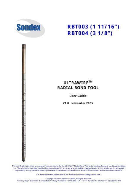
RBT003 (1 11/16”)<br />
RBT004 (3 1/8”)<br />
ULTRAWIRE TM<br />
RADIAL BOND TOOL<br />
User Guide<br />
V1.0 November 2005<br />
This User Guide is intended as a general reference source for the UltraWire TM <strong>Radial</strong> <strong>Bond</strong> <strong>Tool</strong> and principles of cement bond logging relating<br />
to it. The information and data provided has been checked for accuracy where possible. However Sondex and its employees do not accept<br />
responsibility for any decisions made by the reader or data results obtained from the use of this document and its associated materials.<br />
For more information please refer to our manuals or contact sales@sondex.com.<br />
Copyright © Sondex Wireline Ltd 2005. All Rights Reserved.<br />
� Saxony Way � Blackbushe Business Park � Yateley �Hampshire � GU46 6AB � UK Tel +44 (0) 1252 862 200 Fax +44 (0) 1252 862 349
UltraWire TM <strong>Radial</strong> <strong>Bond</strong> <strong>Tool</strong> RBT<br />
_________________________________________________________________<br />
Functional Description<br />
The prime use for the <strong>Radial</strong> Cement <strong>Bond</strong> <strong>Tool</strong> is to assure the asset owner of hydraulic isolation between<br />
producing and non-producing zones, and the integrity of the well, by the effective placement of the cement<br />
between the well tubulars (typically casing) and the formation. Poor cement can result in unwanted water or gas<br />
production, fluid migration in the annulus and inadequate support of the casing. In some instances the safety and<br />
integrity of the entire well can be threatened.<br />
The ideal situation:<br />
In an ideal situation the cement is of good quality (i.e. high compressive strength), has high bond strength<br />
between formation-cement and casing-cement and the cement column will have sufficient length for hydraulic<br />
isolation.<br />
Possible Problems:<br />
If the casing is not cemented into the well properly this can be detrimental to the integrity of the well and lead to<br />
fluid migration and communication between zones. Correct diagnosis is the key to remediation of the problem.<br />
Cement bond logging tools such as the RBT provide an answer as to how good or bad the cement is however<br />
sometimes the data from additional logging tools may be required. Below is an illustration of potential problems<br />
that can occur when the cement quality and bond are poor.<br />
__________________________________________________________________________________________________________________________<br />
Copyright © Sondex Wireline Ltd 2005. All Rights Reserved. Version 1.0 Page 2 of 20
UltraWire TM <strong>Radial</strong> <strong>Bond</strong> <strong>Tool</strong> RBT<br />
_________________________________________________________________<br />
A: Pressure on Casing A poor cement bond to the formation has allowed gas from a gas zone to<br />
percolate into the casing annulus causing high casing pressure which can<br />
endanger the well.<br />
B: Pollution of Groundwater Poor cement is allowing cross flow behind casing of saline formation water<br />
into a freshwater aquifer. This would also corrode the casing.<br />
C: Good Zonal Isolation A zone is isolated and has good cement bond when fluids from the zone<br />
cannot flow behind the casing. An approximation of how much cement<br />
would be needed for good isolation, [2 x casing size” - 5] = cement<br />
column in feet*, e.g. for 7” casing this would be 9ft of good cement.<br />
D: Water flow behind pipe Poor cement is allowing unwanted water flow from a lower formation to<br />
enter the well bore and be produced to surface. Production logging could<br />
be used to identify the water entry point and bond logs used confirm<br />
cement quality at that point.<br />
* This formula is used only as a guide. Cement reference manuals should be used to accurately determine the cement column. Sondex accepts<br />
no responsibility for any results obtain or decisions made by using this formula.<br />
Oilwell cementing is a technologically advanced science. Despite this problems can occur, especially in deviated<br />
wells and those where the formation pressure is depleted.<br />
It is not unusual for channels to occur where there is no cement, they provide a path for fluid migration; thus it is<br />
important that logging tools are run that can reliably identify these channels. Though conventional cement bond<br />
tools can indicate the quality of the formation-cement and casing-cement bonds, they cannot identify channelling<br />
in the cement conclusively. <strong>Radial</strong> bond tools allow the client to obtain a circumferential ‘cement map’ of the<br />
casing-cement bond enabling better identification channels.<br />
In addition to channelling there are documented cases where helical buckling of casing has occurred due to a<br />
combination of sand production and inadequate support of the casing with cement. Various placement methods<br />
have been developed to deal with these problems. However, there is no substitute in the construction of critical<br />
wells for checking the condition of the cement by running a cement bond log. In the past some wells were<br />
completed without running a cement bond log, there may now be a need to bond log these wells.<br />
Cement Channelling<br />
Cement channels are longitudinal pockets with no cement. This can<br />
happen when the mud is not adequately flushed from the wellbore during<br />
the cementing process (this is accentuated when the casing is not<br />
centralised). It can also be caused by gas or water migration during the<br />
time that the cement is curing and in high angle wells where heavy cement<br />
sinks to the low side of the wellbore leaving little or no cement on the high<br />
side. Standard CBL tools, average cement bond quality around the whole<br />
pipe and cannot indicate, relative to high or low side of the pipe, where<br />
the changes occur. On a traditional CBL map, channels show up as low<br />
compressive strength cement/intermediate bond.<br />
Low compressive strength cement<br />
If the cement is poor quality or the wrong type for the well the<br />
compressive strength of the cement may be reduced. Also the situation<br />
may occur where cement further up the hole sets prematurely which<br />
isolates the hydrostatic pressure and allows the pressure of the uncured<br />
cement to drop to formation pressure. When this happens the cement can<br />
be polluted by formation fluids and thus become porous and permeable.<br />
For example tests have shown gas polluted cement to have a permeability<br />
as high as 5 md. The RBT produces a cement map which allows the oil<br />
Formation<br />
Gas<br />
polluted<br />
Cement<br />
Formation<br />
Casing<br />
__________________________________________________________________________________________________________________________<br />
Copyright © Sondex Wireline Ltd 2005. All Rights Reserved. Version 1.0 Page 3 of 20
UltraWire TM <strong>Radial</strong> <strong>Bond</strong> <strong>Tool</strong> RBT<br />
_________________________________________________________________<br />
company to differentiate chanelling from low compressive strength cement and identify where it occurs in relation<br />
to pipe high or low side.<br />
In both the above situations the cement is not fulfilling it’s prime function which is to hydraulically isolate the<br />
formations.<br />
Construction of the UltraWire TM <strong>Radial</strong> <strong>Bond</strong> <strong>Tool</strong><br />
• An omni-directional piezoelectric transmitter crystal<br />
generates acoustic energy in response to an electrical<br />
signal sent from the tool electronics. The pulsed sonic<br />
signals are at 18 Khz (3 1 /8” tool) or 22 kHz (1 11 /16” tool).<br />
• This acoustic energy travels at different speeds as a<br />
wavefront through the mud, casing cement and formation.<br />
During this time the signal is also attenuated.<br />
• Sonic dampers within the tool prevent the transmitted<br />
signals travelling down through the tool to the receivers<br />
below.<br />
• At 3ft (1m) from the transmitter is a segmented<br />
piezoelectric radial receiver. Each segment captures the<br />
returning acoustic energy and converts it into an electrical<br />
signal. As each segment detects the acoustic energy of a<br />
portion of the casing it allows the creation of a cement<br />
map.<br />
• Internally the individual signals from the segments are<br />
electrically combined to obtain the omni directional<br />
amplitude which is equivalent to the standard 3ft signal from non segmented CBL tools.<br />
• At 5ft from the transmitter is an omni directional piezoelectric receiver. This position has a greater depth of<br />
investigation and is used to record the waveform trace from which the Variable Density Log (VDL) is<br />
produced. In general the VDL is used to assess the cement-formation bond and CBL for the casing-cement<br />
bond.<br />
• The sonic signals are received by the main analogue circuit board, conditioned and then portions of the<br />
waveform are digitized. From the 3ft segmented receivers the portion of the signal between 170-370 µs is<br />
digitized and from the 5ft receiver the full waveform 200-1200 µs is digitized.<br />
• The digitized waveform data is stored in temporary memory and on command from the UltraWire TM<br />
controller or UMT memory recorder the digitized waveform data is transmitted to surface via the XTU or<br />
recorded into the UMT memory recorder.<br />
• Additional UltraWire TM Gamma Ray and CCL tools are run in the string for depth correlation. The RBT can<br />
also be run with an UltraWire TM temperature logging tool.<br />
__________________________________________________________________________________________________________________________<br />
Copyright © Sondex Wireline Ltd 2005. All Rights Reserved. Version 1.0 Page 4 of 20
UltraWire TM <strong>Radial</strong> <strong>Bond</strong> <strong>Tool</strong> RBT<br />
_________________________________________________________________<br />
• The RBT is run between strong centralisers; if the tool is not properly centralized data integrity is<br />
compromised. As little as 1/4” off centre can reduce the casing arrival amplitude by up to 2/3 of the signal.<br />
• Additional Sondex UltraWire TM tools can be run in series with the RBT if required.<br />
• The top and bottom tool connections are Sondex-GO.<br />
RBT tools for high temperature environments<br />
For operation in very high temperature wells, 3 1 /8” UltraWire TM RBT can be encased in a flask; this option will be<br />
available from 2006. The temperature rating of the tool increases to 400 o F (204 o C) and pressure rating to 30,000<br />
psi (207 MPa). The string is made up of 2 modules - UltraLink TM telemetry/gamma ray/CCL in one flasked sub and<br />
the RBT tool in another. As with all UltraWire TM the RBT is fully compatible with other tools using this telemetry.<br />
For more information on flasked RBT tools please contact Sondex.<br />
Theory of Measurement of the <strong>Radial</strong> <strong>Bond</strong> <strong>Tool</strong><br />
Cement bond tools use acoustic signals to evaluate the condition of the cement.<br />
• A piezoelectric crystal is used to convert pulsed electrical<br />
energy to sonic energy for transmission. Reciever<br />
piezoelectric crystals are used to convert the arriving<br />
acoustic energy into electrical energy for recording.<br />
• A high frequency acoustic pulse is transmitted out to the<br />
casing at regular intervals.<br />
• Sound travels through the borehole fluid, contacts the<br />
casing and travels along it before returning through the<br />
borehole fluid back to the receiver.<br />
• Some of the signal will pass through the casing into the<br />
cement, and into the formation before it is returned.<br />
• The segmented receiver 3ft from the transmitter detects<br />
the early part of the returning signal to determine the<br />
casing-cement bond.<br />
• The single crystal receiver 5ft from the transmitter detects the later part of the signal that comes from the<br />
cement and formation and is used to generate a VDL which is used to evaluate the cement-formation<br />
bond.<br />
• The return signals contain components from several sources - compressional waves returning from the<br />
casing and fluid, and also compressional/shear waves from the cement and formation.<br />
• The waveform is used to interpret the cement bond.<br />
__________________________________________________________________________________________________________________________<br />
Copyright © Sondex Wireline Ltd 2005. All Rights Reserved. Version 1.0 Page 5 of 20
UltraWire TM <strong>Radial</strong> <strong>Bond</strong> <strong>Tool</strong> RBT<br />
_________________________________________________________________<br />
The diagram on the left illustrates the different components of the<br />
received signal. The recievers record the composite signal comprised of<br />
casing, formation, cement and fluid arrivals. In general the casing has<br />
the highest sonic velocity so this signal arrives first followed by the<br />
formation signals. In very hard formations with high sonic velocity<br />
(called ‘fast’ formations) the formation signals can arrive first and<br />
interfere with the casing returns.<br />
• Sonic energy reverberates within the casing.<br />
• If the casing is unbonded the amplitude of the casing arrival will<br />
be high.<br />
• If the casing is bonded the amplitude of the casing arrival will be<br />
low.<br />
Curves on the log.<br />
Amplitude<br />
By measuring the amplitude of the casing arrival we have a way of<br />
evaluating the casing-cement bond. An analogy is to imagine the casing<br />
as if it were a bell being struck by a hammer. If the bell was clamped<br />
when it was struck the ringing would be low and dull – it is said to be<br />
attenuated; this would equate to there being cement behind the casing.<br />
If the bell is free it rings loud and strong; the signal is not attenuated<br />
and there is no cement behind the casing.<br />
• For the casing-cement bond the 3ft signal is used. Typically, at<br />
this spacing the casing signal is usually separated from the<br />
formation signals.<br />
• The amplitude measurement is made within a specific window in time known as a “Gate”. This corresponds<br />
to the casing arrival or ‘E1’.<br />
• The highest point within the “Gate” is the amplitude measurement.<br />
• This amplitude is plotted on the log and scaled in millivolts.<br />
Travel Time curve (also known as Arrival or Transit Time)<br />
The time taken between transmitter firing and the recievers detecting a<br />
signal above a set amplitude is also measured.<br />
• Travel time is the time between the firing of the transmitter and<br />
the first point that the signal meets a fixed detection level.<br />
• The travel time measurement will increase or “Stretch” as the<br />
amplitude of the E1 decreases.<br />
• If the amplitude of E1 decreases below the threshold level, the<br />
reading will “Cycle Skip” and trigger on the E3 or later.<br />
__________________________________________________________________________________________________________________________<br />
Copyright © Sondex Wireline Ltd 2005. All Rights Reserved. Version 1.0 Page 6 of 20
UltraWire TM <strong>Radial</strong> <strong>Bond</strong> <strong>Tool</strong> RBT<br />
_________________________________________________________________<br />
Using travel time to cross check the signal response:<br />
i) Observe variation in transit time in areas of the well that indicate a good bond.<br />
ii) Check for good centralisation of the tool in areas where E1 can be detected.<br />
iii) Identify any fast formations where the first arrival will come from the formation and thus mask the<br />
casing arrivals. In fast formations formation arrivals in the casing ‘gate’ will falsely show the casing as<br />
non bonded. In this situation the travel time is less than the expected casing arrival time. A further<br />
check to verify a fast formation is if the difference in travel time between the 3ft and 5ft recievers is<br />
less than 114 µs.<br />
iv) Check recorded transit time with transit time reference charts for known formations.<br />
The Variable Density Log (VDL)<br />
The VDL is used to illustrate the composite wave. This allows qualitative evaluation of the casing-cement and<br />
cement-formation bonds. The VDL is a ‘top down’ (Z-axis) plot of the amplitude of the composite sonic wave in<br />
grey scale. The diagram below shows the sonic waveform in track 3 and it’s equivalent VDL in track 2.<br />
Additional curves and displays from the RBT tool<br />
Basic CBL tools have only 3ft and 5ft recievers, this is not usually enough to identify and locate channelling. The<br />
RBT produces additional data from each of the segmented crystals at 3ft which can be plotted on the log as 3<br />
curves showing maximum, minimum and average amplitude and also as a ‘cement map’ where the amplitude of<br />
each segment is converted into a colour or gray scale. An illustration is overleaf.<br />
__________________________________________________________________________________________________________________________<br />
Copyright © Sondex Wireline Ltd 2005. All Rights Reserved. Version 1.0 Page 7 of 20
UltraWire TM <strong>Radial</strong> <strong>Bond</strong> <strong>Tool</strong> RBT<br />
_________________________________________________________________<br />
Specifications<br />
The UltraWire TM <strong>Radial</strong> <strong>Bond</strong> tools are available in 1 11 /16” and 3 1 /8” diameter versions. The 1 11 /16” tool has 6<br />
segments at the 3ft receiver and the 3 1 /8” tool has 8 segments at the 3ft receiver. The choice of tool is dictated by<br />
the casing size the 3 1 /8” tool will work better in larger casing but when re-entering production wells with small<br />
restrictions a 1 11 /16” tool can be passed through 2 7/8” tubing to log in casing sizes up to 7”.<br />
The standard UltraWire TM RBT is temperature and pressure rated to 350 o F (177 o C) and 20,000 psi (138 MPa)<br />
respectively. Non UltraWire TM versions of the tools using analogue telemetry are available with temperature and<br />
pressure ratings of 400 o F (204 o C) /20,000 psi (138 MPa) for the 1 11 /16” tool and 375 o F (191 o C) / 20,000 psi (138<br />
MPa) for the 3 1 /8” tool.<br />
Primary calibration is within a 5.5” pressurized calibration tank. Calibration verification at the wellsite is done in<br />
area of known free pipe (assuming there is truly free pipe).<br />
The prime quantifiable measurements are the 3ft omni and radial amplitudes which correspond to casing-cement<br />
bond and the 5ft measurement which is generally used for the cement-formation bond; this is considered to be<br />
qualitative.<br />
__________________________________________________________________________________________________________________________<br />
Copyright © Sondex Wireline Ltd 2005. All Rights Reserved. Version 1.0 Page 8 of 20
UltraWire TM <strong>Radial</strong> <strong>Bond</strong> <strong>Tool</strong> RBT<br />
_________________________________________________________________<br />
<strong>Tool</strong> power requirements are 16-18VDC (the same as any other UltraWire TM tool) and 50-60 mA. The tools can be<br />
run in combination with all other Sondex UltraWire TM tools. They can be operated in surface read-out mode or in<br />
memory mode.<br />
Suitable borehole fluids: Oil, Fresh Water, Brine. The fluid should be static; the tool will not work well in gas cut or<br />
moving fluids because the signal is rapidly dispersed before it is detected by the receivers.<br />
Specification 1 11 /16” UltraWire TM <strong>Radial</strong> <strong>Bond</strong> 3 1 /8” UltraWire TM <strong>Radial</strong> <strong>Bond</strong><br />
Casing/Tubing Range 2.0 to 7.5”<br />
3.75” to 13 3/8”<br />
(50.8 to 191 mm)<br />
(95 to 340 mm)<br />
Length 9.9ft<br />
9.5ft<br />
(3.03m)<br />
(2.89m)<br />
Primary curves Amplitude (3ft, <strong>Radial</strong> 1-6),<br />
Amplitude (3ft, <strong>Radial</strong> 1-8),<br />
Amplitude Map, Travel Time (3ft), Amplitude Map, Travel Time (3ft),<br />
VDL (5ft), Rotation<br />
VDL (5ft), Rotation<br />
Optional additional curves (plus<br />
any UltraWire TM Scintillation Gamma Ray, CCL, Scintillation Gamma Ray, CCL,<br />
tool) typically:<br />
Borehole Temperature<br />
Borehole Temperature<br />
Transmitter Freq / interval ≈18 kHz ≈22 kHz<br />
Number of radial receivers 6 at 3ft 8 at 3ft<br />
3 ft Receiver (piezoelectric) Yes (combined radials) Yes (combined radials)<br />
5ft Omni Receiver (piezoelectric) Yes Yes<br />
High side indicator/rotation sensor Yes Yes<br />
Precision
UltraWire TM <strong>Radial</strong> <strong>Bond</strong> <strong>Tool</strong> RBT<br />
_________________________________________________________________<br />
<strong>Tool</strong> Calibration<br />
There are 2 basic calibrations of the tool, for both the Sondex RCT001 pressurized calibration tank is used.<br />
Shop Calibration of the Receiver crystals<br />
The RBT is checked and calibrated during manufacture; however it is recommended that calibrations should be<br />
performed as part of the annual maintenance schedule or after a major service or repair. To do this a calibration<br />
test harness (part of p/n 4000006 Kit-HST) is fitted to the tool such that the transmitter/receiver sonde is inside<br />
the calibration tank and the electronic section is outside of it; the sonde should be centralised and the tank filled<br />
with water. Pressure of 500-700 psi is applied and the RBT transmitters turned on.<br />
The signal gain of each individual receiver are set in the lab by fitting different resistors on the amplifier board and<br />
comparing the signal to an on-screen ‘oscilloscope’ which is included in the Warrior acquisition software. In the<br />
calibration tank under pressure, the received casing signal amplitude (E1) from each of the radials, the sum of the<br />
radials (near receiver) and the far receiver should be 1.0V +/- 0.02v.<br />
This master calibration is performed by Sondex Canada Inc on manufacture and can be repeated at client’s<br />
locations when required.<br />
Pre-job Calibrations<br />
It can be difficult to find truly free pipe in a well. Therefore before a job the free pipe calibration is performed<br />
using the calibration tank. To simulate downhole conditions and to compress any air voids the tank is filled with<br />
water and pressurized to 500 psi using a hand pump.<br />
Setting the casing signal gates and travel time windows<br />
• The Sondex UltraLink TM RBT service is selected and the tool<br />
is started up.<br />
• The waveform window is loaded automatically by the<br />
acquisition software. This shows the waveforms of the 3ft,<br />
5ft and individual receiver segments.<br />
• Using Edit Variables the operator sets the casing OD (for<br />
calibration use 5.5”).<br />
__________________________________________________________________________________________________________________________<br />
Copyright © Sondex Wireline Ltd 2005. All Rights Reserved. Version 1.0 Page 10 of 20
UltraWire TM <strong>Radial</strong> <strong>Bond</strong> <strong>Tool</strong> RBT<br />
_________________________________________________________________<br />
• From the onscreen viewer select the waveform to work with.<br />
• Select the gate position button and using this button and gate width buttons set the timing gate at the<br />
correct position and width on the waveform, this should correspond to E1 peak.<br />
• The width of the gate is typically 20-30 µS. The gate for the 5ft receiver should be approximately 114 µS<br />
later than the 3ft gate.<br />
• Select the travel time button and using this button and gate width buttons position the travel time window<br />
to cover at least the first 3 peaks of the waveform. The amplitude threshold should be set high enough to<br />
avoid any baseline noise.<br />
• Perform the same operation for each waveform. Care should be taken with the travel time window for the<br />
Near and Far waveforms.<br />
• Save the free-point gate position file for further use.<br />
Setting the Free-point Calibration<br />
Before starting, check the amplitude gates have been positioned correctly.<br />
• Select Action – Calibrate - SCBL Master Free Pipe Calibration. The SCBL amplitude calibration window is<br />
displayed.<br />
• Edit the Target Pipe Amplitude to show 100 mV (the standard value for 5.5” casing is 71.9 mV however<br />
this is to compensate for the fact that the calibration tank is surrounded by air rather than fluid as you<br />
would get in a well).<br />
• Edit the Target Sector E1 amplitude as 100.<br />
• Select Sample-Begin to determine the calibration gains and offsets and save the calibrations.<br />
• Select Action – Calibrate - SCBL Master Zero. Save the calibrations.<br />
Setting the Zero Calibration<br />
Before starting the amplitude gates should have been correctly positioned to measure the baseline before the<br />
casing waveforms arrive. Initially the gate positions will have to be set up and saved. For subsequent runs the<br />
saved gate position file can be loaded. As the tool is digital the baseline should be very close to zero.<br />
• Perform the same steps as those for setting the free-point but set the Target Pipe Amplitude to zero and<br />
save.<br />
Calibrating in memory mode.<br />
In memory mode the calibrations are performed by running the tool in monitor mode via the UMT and MIP and<br />
viewing the waveforms with Warrior as you would with surface readout.<br />
Surface Readout or Memory Mode?<br />
The UltraWire TM digital system allows jobs to be performed in surface read-out (SRO) or memory mode. This is<br />
usually decided by the client though the service company can make recommendations. With surface readout RBT<br />
logging, the tool data and depth data are merged on acquisition. With memory RBT logging, the two tool data sets<br />
are stored in memory and merged after the job.<br />
__________________________________________________________________________________________________________________________<br />
Copyright © Sondex Wireline Ltd 2005. All Rights Reserved. Version 1.0 Page 11 of 20
UltraWire TM <strong>Radial</strong> <strong>Bond</strong> <strong>Tool</strong> RBT<br />
_________________________________________________________________<br />
Advantages of SRO RBT opera ions. t It is a big advantage to see real time tool responses and log curves because<br />
this allows the logging engineer and wellsite witness to make decisions on what is happening downhole before the<br />
tool is pulled out of the well. For example, a repeat section can be logged over zones of particular interest where<br />
there may be channels or very poor cement bond. If a section of free pipe is identified in the well the tool setup<br />
can be cross checked. When the logging operation is taking place in a very hot well or where rig costs are high<br />
(and non-production time must be minimised) it is always best to perform real time logging.<br />
Advantages of Memory RBT operations. The advantage of memory operations is that minimal equipment and<br />
personnel are needed and thus the service is very cost effective. The tools are easily transported and can be<br />
deployed on using slickline or coiled tubing. <strong>Tool</strong> data is recorded directly into the memory section of the tool<br />
without being transmitted up-hole via the cable, which is a particular advantage in sour wells (with hydrogensulphide)<br />
and where rig power is poor.<br />
Memory logging also provides an easy start up for new or small service companies and may fit in well with existing<br />
coiled tubing and slickline services.<br />
Make up of <strong>Radial</strong> <strong>Bond</strong> <strong>Tool</strong> Logging Strings<br />
The make up of the toolstring is dependent upon the size of tool used and whether the tool is run in SRO or<br />
memory mode.<br />
__________________________________________________________________________________________________________________________ Copyright © Sondex Wireline Ltd 2005. All Rights Reserved. Version 1.0 Page 12 of 20<br />
Illustration of SRO and Memory RBT systems
UltraWire TM <strong>Radial</strong> <strong>Bond</strong> <strong>Tool</strong> RBT<br />
_________________________________________________________________<br />
Typical toolstring components<br />
XTU (SRO) For surface readout an XTU telemetry controller is used at the top of the string. This<br />
interrogates the UltraWire TM tools and transmits the data to surface via UltraLink TM . <strong>Tool</strong><br />
power is sent via the cable from control panels in the logging unit.<br />
UMT (MRO) For memory readout a programmable UMT memory recorder is used at the top of the<br />
string. This interrogates the UltraWire TM tools and records the data into EEPROM<br />
memory. The UMT and logging string is powered by a high temperature lithium battery.<br />
Roller<br />
Centralisers<br />
and knuckle<br />
joints<br />
The RBT tool must be run centralized. For the 1 11 /16” RBT, 4 arm roller centralisers<br />
PRC034 are used. These have a high centralisation force and can be used in casing sizes<br />
up to 9 5 /8. The 3 1 /8” RBT is heavy; use either the 2 1 /8” PRC041 or 2¾” PRC057<br />
centralisers. The design of the centraliser wheel assembly (with tandem rollers)<br />
minimizes ‘road noise’ from vibrations – noise can mask the sonic signal detected by the<br />
tool receivers. If using 1 11 /16” centralisers with the heavy 3 1 /8” RBT then the toolstring<br />
must be made up vertically which may require a special clamp. An additional centraliser<br />
can be placed above the XTU or UMT if required. In highly deviated wells knuckle joints<br />
can also be de-couple the RBT and associated centralisers from the rest of the string to<br />
assist with centralization.<br />
Gamma Ray An UltraWire TM scintillation gamma ray tool is used for depth correlation.<br />
CCL An UltraWire TM casing collar locator is used to produce a GR/CCL (completion) log and for<br />
depth correlation. For the 3 1 /8” RBT a 3 1 /8” CCL is used.<br />
<strong>Radial</strong> <strong>Bond</strong><br />
<strong>Tool</strong><br />
Temperature<br />
(Optional)<br />
A 1 11 /16” <strong>Radial</strong> <strong>Bond</strong> tool is used for tubing or casing sizes from 2.00” to 7.50”. The 3ft<br />
receiver has 6 segments. The 5 ft receiver is omni-directional.<br />
A 3 1 /8” <strong>Radial</strong> <strong>Bond</strong> tool is used for tubing or casing sizes 3.75” to 13.38”. The 3ft<br />
receiver has 8 segments. The 5 ft receiver is omni-directional.<br />
A temperature tool can be included in the string to locate the top of the cement and<br />
identify fluid movement behind the casing. Cement curing is exothermic thus a rise in<br />
temperature may be detected where the cement is placed.<br />
Bull Nose If no additional UltraWire TM tools are run a bull nose is required for the bottom of the<br />
string. The bull nose contains an UltraWire TM terminator.<br />
Typical RBT String Lengths<br />
A full RBT string with tandem knuckle joints, centralisers, gamma ray and CCL has the following dimensions:<br />
<strong>Tool</strong> Type MRO string length MRO string wt. SRO string length SRO string wt.<br />
1 11 /16” RBT 23.0 ft 107 lbs 21.3 ft 96 lb<br />
3 1 /8” RBT 22.6 ft 207 lbs 20.9 ft 196 lb<br />
Acquisition Software<br />
SRO RBT logging is performed using a Sondex modified version of the Windows® based Warrior software. The<br />
software includes calibration routines and a variety of RBT data presentation formats. The UltraLink TM RBT data is<br />
routed to the PC via an UltraLink TM panel or via an UltraLink TM module fitted within a Warrior STIP panel.<br />
Memory RBT logging is performed using Sondex Ultrawire Memlog TM for the UMT memory recorder. The<br />
software programs the tools, merges the data and outputs the merged logging passes as raw data into the Warrior<br />
database for post acquisition re-calculation and production of the logs.<br />
__________________________________________________________________________________________________________________________<br />
Copyright © Sondex Wireline Ltd 2005. All Rights Reserved. Version 1.0 Page 13 of 20
UltraWire TM <strong>Radial</strong> <strong>Bond</strong> <strong>Tool</strong> RBT<br />
_________________________________________________________________<br />
Performing the logging job<br />
• The tools are pre-job calibrated at surface using the 5.5” pressurized calibration tank. This sets the gains<br />
and offsets for the correct amplitude in 5.5” free pipe. The free pipe amplitude in the well will vary<br />
depending on the casing size.<br />
• Connected RBT to centralisers and other UltraWire TM tools in the string, rigged up and run in the well.<br />
Running in hole/pulling out of hole speed should not exceed 50 m/min.<br />
• For amplitude corrections the Warrior well variables are set for the casing size to be logged.<br />
• If a section of casing with free pipe is observed the amplitude gates are re-set to correspond for the arrival<br />
time of E1 peak for that casing size. If no free pipe is seen use a saved gate position file for that casing<br />
size. In memory mode the gate setting is made after the job but a pre-established gate position file can be<br />
used as a starting point. It is also possible to specify an auto gate look up file which is referred to by cross<br />
reference with the casing size in the zoned variables.<br />
• For SRO operations the tools should be depth correlated downhole to a reference log, before the cement<br />
log is run. Position the RBT below the logging interval, where there is enough rat-hole this should be a<br />
distance equivalent to the overall tool length below the interval; this will ensure that no data is missed<br />
once the log is started. In memory mode data should be recorded from below the logging interval and the<br />
log is depth matched after the job.<br />
• The toolstring is logged up the hole at a recommended 30 to 45 ft/min (10-15 m/min). However, the high<br />
bandwidth of UltraWire TM allows logging speeds up to 100 ft/min (30 m/min) when rig time is paramount.<br />
• In SRO mode the engineer should check that the gate settings remain correct, these can be adjust if E1<br />
drifts outside the gate or a new casing size is seen. A new casing size can be handled automatically if the<br />
auto gate function is used.<br />
• Perform a repeat log over sections where there may be channels, changes in cement quality, fast<br />
formation, etc. For memory logging it is recommended that a repeat section over the whole interval be<br />
done if there is enough memory capacity. If not the zone of main interest should be repeated.<br />
• When logging is complete the tool string is pulled out of hole and rigged down.<br />
__________________________________________________________________________________________________________________________<br />
Copyright © Sondex Wireline Ltd 2005. All Rights Reserved. Version 1.0 Page 14 of 20
UltraWire TM <strong>Radial</strong> <strong>Bond</strong> <strong>Tool</strong> RBT<br />
_________________________________________________________________<br />
Job Flowchart Surface Readout<br />
Job Flowchart Memory Readout<br />
__________________________________________________________________________________________________________________________<br />
Copyright © Sondex Wireline Ltd 2005. All Rights Reserved. Version 1.0 Page 15 of 20
UltraWire TM <strong>Radial</strong> <strong>Bond</strong> <strong>Tool</strong> RBT<br />
_________________________________________________________________<br />
EXAMPLE LOGS<br />
Good cement with free pipe on top<br />
In this example there is free pipe at the top of the log. There is high casing amplitude, the arrival time corresponds<br />
to the casing arrival time, reverberation can be seen on the VDL and the cement map shows 0% cement bond. At<br />
the bottom the pipe is well bonded, signal amplitude is very low, arrival time increases and there is 100% cement<br />
bond. Formation arrivals can be seen on the VDL indicating a good cement-formation bond; where present<br />
formation arrivals can be loosely correlated to the gamma ray as formation type changes.<br />
Good casing-cement bond, poor cement-formation bond<br />
In this example the pipe is bonded to the cement, but the cement is not bonded to the formation. The signal<br />
amplitude is low, arrival time increases and the cement map shows 100% cement. However qualitatively we can<br />
say that the cement-formation bond is poor because we cannot see the formation arrivals. The casing may have a<br />
thin cement sheath. Note though that unconsolidated formations can look a little like this.<br />
__________________________________________________________________________________________________________________________<br />
Copyright © Sondex Wireline Ltd 2005. All Rights Reserved. Version 1.0 Page 16 of 20
UltraWire TM <strong>Radial</strong> <strong>Bond</strong> <strong>Tool</strong> RBT<br />
_________________________________________________________________<br />
Poor bond casing cement, good bond to formation (possible micro annulus)<br />
In this example there is high casing amplitude, the arrival time matches the casing arrival time and the cement<br />
bond shows relatively low bond quality. The VDL shows weak formation arrivals. It is also possible that this could<br />
be a micro annulus. The log should be repeated with the well fluids under low pressure. If a micro annulus exists<br />
the casing amplitude under pressure will be lower than that with no pressure.<br />
Channelling<br />
In this example there is channelling. The bond is shown as intermediate on the CBL but the radial segments show<br />
that there is approximately 30% cement bonded to the casing and the rest is poorly bonded or not present. Above<br />
and below the channel is good cement.<br />
__________________________________________________________________________________________________________________________<br />
Copyright © Sondex Wireline Ltd 2005. All Rights Reserved. Version 1.0 Page 17 of 20
UltraWire TM <strong>Radial</strong> <strong>Bond</strong> <strong>Tool</strong> RBT<br />
_________________________________________________________________<br />
GUIDELINES FOR DATA/INTERPRETATION<br />
Interpretation of a radial cement bond log is often qualitative from a visual appraisal. At the wellsite the engineer<br />
and the client witness will look at the log together in order to agree on the cement condition and any remedial<br />
action. If an immediate decision is not needed the data can reviewed in town.<br />
Travel Time (also known as Arrival/Transit Time)<br />
• For bonded pipe the travel time should increase as it triggers on the E3 peak or later arrivals.<br />
• For free-pipe, the travel time should match the expected time for that casing size.<br />
• If the travel time decreases below casing arrival time and the amplitude drops then suspect<br />
eccentralisation and cross check against the cement map.<br />
• If the travel time decreases below casing arrival time and the amplitude increases suspect fast formations.<br />
• The travel time difference between the 3ft and 5ft receivers should be 114 µs. If it less than this suspect<br />
fast formations.<br />
Amplitude<br />
• For bonded pipe the amplitude should be low.<br />
• For free-pipe the amplitude will be high.<br />
• If the amplitude is intermediate cross check with the cement map to see if the problem is cement<br />
channelling or low compressive strength cement.<br />
Cement Map<br />
• In bonded pipe the cement map should show uniform low amplitude.<br />
• In non bonded pipe the cement map should show uniform high amplitude.<br />
• In cases with channelling the signal amplitude at some of the receiver segments will be high.<br />
• In cases of low compressive strength all the segments will show intermediate amplitude.<br />
• If the tool is eccentralised the cement map will be non uniform.<br />
• If the pipe is lying against the formation the cement map may be non uniform.<br />
<strong>Bond</strong> Index<br />
<strong>Bond</strong> Index is essentially the ratio of measured signal attenuation (taken from the log) to maximum attenuation.<br />
Readings of un-bonded pipe (free pipe amplitude = zero attenuation), bonded pipe (close to zero amplitude =<br />
maximum attenuation) and log value are used. A bond index of 0.8 or higher is accepted as indicating good<br />
cement. For cement showing a bond index of 0.8 a rule of thumb for the required interval of good cement for<br />
hydraulic isolation in ft is 2 x Casing OD – 5. For example in 9 5/8” casing the minimum interval of good cement for<br />
hydraulic isolation would be 13.25ft.<br />
Compressive Strength.<br />
Compressive strength is a measure of the strength of the cement to support the casing and its resistance to<br />
crushing. The units of measurement are psi. It is a non linear calculation from amplitude, casing size and casing<br />
thickness. For a manual interpretation nomograms may be found in industry text books. Higher amplitude equates<br />
to low compressive strength, low amplitude equates to high compressive strength. With standard CBL tools it is<br />
almost impossible to differentiate between low compressive strength cement and a cement channel. To use the<br />
nomograms correctly the tool should be properly calibrated.<br />
Variable Density Logs<br />
This is a qualitative interpretation of the complete waveform. In an ideal situation the amplitude of the casing<br />
arrival is low (or not existent) and the formation arrivals can be seen.<br />
__________________________________________________________________________________________________________________________<br />
Copyright © Sondex Wireline Ltd 2005. All Rights Reserved. Version 1.0 Page 18 of 20
UltraWire TM <strong>Radial</strong> <strong>Bond</strong> <strong>Tool</strong> RBT<br />
_________________________________________________________________<br />
POSSIBLE PROBLEMS<br />
Eccentralised <strong>Tool</strong><br />
Centring of the RBT is critical for valid<br />
measurements. If the tool is eccentralised<br />
there are 2 paths for the sonic signal to take<br />
and the waveform at the receiver becomes<br />
smeared. The travel time will be reduced to be<br />
less than the expected travel time and the<br />
amplitude will be too low which will falsely<br />
indicate good bonding. The tool must be well<br />
centralized. Indications on the log will be the<br />
amplitude decreasing at the same time as the<br />
travel time decreases. If the tool is<br />
eccentralised the cement map will not be<br />
uniform.<br />
Fast formations<br />
Fast formations are often very hard rock such as chert where the sonic velocity is unusually high (faster than the<br />
sonic velocity in casing), because of this the formation signals can arrive at the 3ft receiver before the casing<br />
signal. When this happens there will be a high signal within the amplitude gate which will be interpreted as a poor<br />
bond giving a false result. As a check the travel time to the first arrival should be examined, if it is less than the<br />
expected first arrival travel time for that casing size, suspect a fast formation. Indications on the log are increasing<br />
amplitude at the same time as the travel time decreases. The good news in this situation is that casing-cementformation<br />
bonds must be good to detect fast formation i.e. if fast formations are seen then the cement is good.<br />
Micro annulus<br />
A micro annulus is a microscopic gap between the cement and the casing which<br />
has poor acoustic coupling. This can be due to a lowering of pressure in the<br />
casing after the cement job or thermal contraction. The gap has been estimated<br />
in the range of 0.005-0.01” (0.12 to 0.25 mm). It is assumed that a micro<br />
annulus does not compromise hydraulic isolation but the result on a bond log is<br />
to show a medium casing signal amplitude and moderate casing and formation<br />
arrivals. This can result in misinterpretation of the log which shows a poor bond<br />
when actually cement is present. If a micro annulus is suspected the usual<br />
course of action is to re-run the log with the casing under pressure (500 to 1000<br />
psi). If the casing amplitude decreases and the formation signals get stronger<br />
then a micro annulus is suspected and the cement bond is considered to be OK.<br />
Low compressive strength cement<br />
Low compressive strength cement will show as intermediate amplitude. By reference to the cement map it is<br />
possible to determine if the apparent intermediate amplitude is due to a channel, if it is not then nomograms may<br />
be used to calculate the apparent compressive strength. Low compressive strength can occur when insufficient<br />
time has been given for the cement to cure. In this instance a second bond log may be run after the cement has<br />
fully cured.<br />
Foamed or Lite Cement<br />
When formation pressures are low in depleted fields it is not always possible to run standard cement due to lost<br />
circulation or formation fracturing problems. In this event the cement is lightened by foaming with nitrogen or by<br />
running special particulates in the cement. This type of cement provides isolation but has an extremely low<br />
__________________________________________________________________________________________________________________________<br />
Copyright © Sondex Wireline Ltd 2005. All Rights Reserved. Version 1.0 Page 19 of 20
UltraWire TM <strong>Radial</strong> <strong>Bond</strong> <strong>Tool</strong> RBT<br />
_________________________________________________________________<br />
compressive strength, and correspondingly reduced attenuation of the sonic signal. This means that even in well<br />
bonded pipe, the amplitude may not approach zero.<br />
One method for running a CBL in this environment is to find the best bond in the well, cross check against the<br />
cement map for uniformity and assume that the amplitude of the sonic signal at that point corresponds to 100%<br />
bonding. The free pipe signal will be the same as in any other case. Thus, you may end up with an amplitude scale<br />
of perhaps 10 to 100, rather than 0 to 100. This approach can be a tough sell against ultrasonic tools so it may be<br />
necessary to discuss this with the client prior to the job. The ability to produce a cement map will help as it should<br />
show even distribution of the cement with no channels even when the amplitude is not zero.<br />
“Road Noise”<br />
When the tools are moving the centralisers can generate noise which is picked up by the RBT. This is minimized by<br />
using roller centralisers which have 2 wheels on each arm and thus ride over collars. The standard Sondex roller<br />
centralisers are PRC034, PRC041 and PRC057 which have 2 wheels on each arm. The signal amplitude will<br />
decrease as the logging speed is reduced and stop when the tools are stationary. In this case road noise should be<br />
suspected.<br />
Oil Based Mud<br />
Oil based mud has different sonic properties to water based mud. The travel time will be longer and the free pipe<br />
amplitude will be lower. The tool should be re-calibrated in zones with oil based mud. Problems can occur at<br />
pressures above 10,000 psi. Ideally cement bond logs should be run in water based mud with a low particulate<br />
volume.<br />
Eccentralised free pipe<br />
In deviated wells free pipe may rest against the formation and the classic free pipe VDL may not be seen. The CBL<br />
will show high amplitude and medium to strong formation arrivals will be seen on the VDL. Reference to the<br />
cement map may show lower amplitudes where the pipe rests against the formation. The signal response in this<br />
situation could be mistaken for a channel except that they occur over tens of feet (or more) in length which is not<br />
likely to be the case with a channel.<br />
TOOL MAINTENANCE<br />
<strong>Tool</strong> Routine Maintenance<br />
Roller Centralisers Change rollers as required. Inject grease through grease ports. Change ‘O’ rings.<br />
Check continuity and insulation.<br />
Knuckle Joints Inject grease through grease ports. Check continuity and insulation.<br />
Swivel Joint (if used) Change ‘O’ rings. Refill with silicon oil as required.<br />
RBT tool Clean the tool thoroughly after a job (do not use a pressure hose). Inspect and<br />
change seals and ‘O’ rings as required. Before the job perform a calibration.<br />
Gamma Ray and CCL Change housing ‘O’ rings as required. Check for loose screws.<br />
STORA<strong>GE</strong> / TRANSPORT<br />
The tools should be oiled externally with a film of WD40 to prevent possible corrosion and transported within foam<br />
lined protective boxes. The watertight end caps should be fitted and the tools should be protected against shock.<br />
The ‘cans’ around the crystals are thin and can be easily dented do not push screw drivers, sticks or similar items<br />
through the slots on the sonde. NB: The CCL should be stored away from the Gamma Ray tool; the magnetic field<br />
can magnetise the housing which prevents the photomultiplier tube in the gamma ray from working properly.<br />
REFERENCES<br />
Sondex UltraWire TM RBT Manual<br />
Sondex Warrior Software Manual<br />
Cased Hole Log Analysis and Reservoir Performance Monitoring. R.M. Bateman 1985<br />
__________________________________________________________________________________________________________________________<br />
Copyright © Sondex Wireline Ltd 2005. All Rights Reserved. Version 1.0 Page 20 of 20


