3x5 Component Video/Digital Audio Matrix Switch w/RS-232
3x5 Component Video/Digital Audio Matrix Switch w/RS-232
3x5 Component Video/Digital Audio Matrix Switch w/RS-232

You also want an ePaper? Increase the reach of your titles
YUMPU automatically turns print PDFs into web optimized ePapers that Google loves.
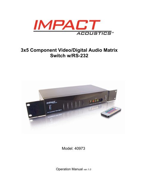
<strong>3x5</strong> <strong>Component</strong> <strong>Video</strong>/<strong>Digital</strong> <strong>Audio</strong> <strong>Matrix</strong><br />
<strong>Switch</strong> w/<strong>RS</strong>-<strong>232</strong><br />
Model: 40973<br />
Operation Manual ver.1.0
Table of Contents<br />
Functions ………………………………………………………………………….1<br />
Package Contents………………………………………………………………...1<br />
Features……………………………………………………………………………2<br />
Connecting Devices…….………………………………………………………2-3<br />
Operating the <strong>Switch</strong><br />
Controlling the <strong>Switch</strong> from the IR Remote…………………………….4<br />
Controlling the <strong>Switch</strong> from the Front Panel………….………………..5<br />
Connecting the Mounting Brackets……………………………………………..6<br />
<strong>RS</strong>-<strong>232</strong> Control……………………………………………………………………6<br />
Factory Default Settings………………………………………………………….7<br />
Replaceable Parts………………………………………………….……………..7<br />
Troubleshooting…………………………………………………………………...7<br />
Specifications……………………………………………………………………...8<br />
Warranty/Important Safety Information………………………………………....9<br />
ii
Operation Manual<br />
<strong>3x5</strong> <strong>Component</strong> <strong>Video</strong>/<strong>Digital</strong> <strong>Audio</strong> <strong>Matrix</strong><br />
<strong>Switch</strong> w/<strong>RS</strong>-<strong>232</strong><br />
Model: 40973<br />
Thank you for purchasing the Deluxe <strong>Component</strong> <strong>Video</strong>/<strong>Digital</strong> <strong>Audio</strong> 3 In / 5 Out <strong>Matrix</strong> <strong>Switch</strong>.<br />
This <strong>Matrix</strong> <strong>Switch</strong> allows you to connect up to three audio and video components to five<br />
televisions or monitors.<br />
We recommend that you read this manual thoroughly and retain for future reference.<br />
Function:<br />
The 40973 allows you to route any of three source device outputs to any of five TV/Monitors<br />
You can also route the same output to all TV/Monitors. This switch supports a range of video<br />
resolutions (480i, 480p, 720p, 1080i, and 1080p) to meet the needs of standard and high<br />
definition video/audio equipment. This matrix switch allows you to treat each output as a<br />
separate “zone”. For example, Output 1 can be designated as the home theater zone, and<br />
Output 2 can be the master bedroom zone. This will allow you to, for example, play a video<br />
game in the living room and at the same time watch a high-definition cable/satellite broadcast in<br />
the bedroom. The <strong>RS</strong>-<strong>232</strong> control enables you to program the switch to work with an<br />
automated remote control system.<br />
Package Contents<br />
• <strong>Matrix</strong> <strong>Switch</strong> (1)<br />
• Remote Control (1)<br />
• Universal Mounting Brackets w/screws (1 set)<br />
• User Manual (1)<br />
1
Features:<br />
• Five <strong>Component</strong> <strong>Video</strong> / TOSLINK Outputs<br />
High quality audio and video output to as many as five A/V devices such as TV displays,<br />
A/V receivers or other A/V devices<br />
• <strong>Component</strong> <strong>Video</strong> Inputs<br />
High quality video support for up to three standard or high-definition sources<br />
• TOSLINK Inputs<br />
<strong>Digital</strong> multi-channel support for up to three audio sources<br />
• Standard Stereo RCA Connectors<br />
Left/right stereo audio support for two-speaker systems<br />
• Push-Button Source Selection<br />
Front panel buttons with tri-color LED for quick input/output identification.<br />
• Slim Line Remote Control<br />
Operates the switch from a distance or program commands into your existing remote<br />
control system<br />
• <strong>RS</strong>-<strong>232</strong> Control<br />
PC Interface for optional use with an automated remote control system<br />
Connecting Devices:<br />
For optimal performance, use high-quality audio and video cables. Use a component video<br />
cable with RCA plugs (not supplied) for all component video connections. Use audio cables with<br />
TOSLINK or RCA plugs (not included) for all audio connections.<br />
The switch’s color-coded jacks make it simple to connect devices to the switch. Green – blue<br />
– red jacks (marked as Y, Pb and Pr) are used for component video, red jacks are for right<br />
channel audio and white jacks for left channel audio.<br />
Before connecting the switch to your digital audio equipment, make sure you perform the<br />
following tasks:<br />
• Power down all components that will be connected to this switch<br />
� Remove the plastic plug that protects the switch’s TOSLINK jack from dust. Keep plastic<br />
plug for future use.<br />
� Remove the cable end protectors from the TOSLINK connector on your TOSLINK cable (not<br />
supplied).<br />
2
Follow these steps to connect the components to the switch.<br />
1. Connect each of the component video outputs from your devices (DVD player, HD<br />
cable/satellite receiver, video game player, etc.) to a set of Inputs 1-3 (Y, Pb and Pr jacks)<br />
on the back or front of the switch.<br />
2. Connect your devices’ TOSLINK outputs to a TOSLINK Input (1-3) jacks on the back or on<br />
front of the switch. If a device does not have a TOSLINK output, connect its stereo L/R<br />
audio outputs to a set of stereo L/R audio Inputs (1-2) jacks on the back of the switch.<br />
Front panel Input 3 features 3.5mm jack for stereo L/R connections. A 3.5mm to RCA “Y”<br />
adapter (not included) must be used for this connection.<br />
Note: This device does not convert TOSLINK to analog audio or analog audio to<br />
TOSLINK. <strong>Audio</strong> switching follows video.<br />
3. Connect component video Outputs (1-5) Y, Pb and Pr of the matrix switch to the<br />
component video inputs of up to five TVs/monitors.<br />
4. Using a TOSLINK cable, connect the ends from the TOSLINK Outputs (1-5) on the switch<br />
to the TOSLINK inputs on up to five A/V receivers (or digital audio recorders). If devices<br />
do not have TOSLINK inputs, use RCA audio cables to connect from the matrix switch’s<br />
L/R audio Output (1-5) to RCA L/R audio inputs on five displays or A/V receivers.<br />
Example diagram:<br />
Front Input<br />
Rear Panel<br />
3
Operating the <strong>Switch</strong>:<br />
Controlling the switch with the infrared remote control<br />
1. Press POWER ON to turn on the matrix switch.<br />
2. Press 1 – 5 on either the green, red, or orange panels to change the video display of the<br />
device you are using. Green panel represents Input 1. Red panel represents Input 2.<br />
The orange panel represents Input 3.<br />
Green<br />
Panel<br />
Red<br />
Panel<br />
Orange<br />
Panel<br />
Example 1 – You would like to route your DVD player on Input<br />
3 to Output 1. Press the number 3 button on the Output 1<br />
row. The LED of Output 1 on the front panel of the switch will<br />
be illuminated orange.<br />
Example 2 – You would like to route your game console on<br />
Input 1 to Output 2, but continue watching the DVD movie<br />
from example 1. Press 1 on Output 2 row. The LED of<br />
Output 2 on the front panel of the switch will be illuminated<br />
green.<br />
Example 3 – You wish to now route your cable box connected<br />
to Input 2 to the displays of both Output 1 and Output 2 at the<br />
same time. Press 2 on Output 1 row, and then press 2 on<br />
Output 2 row. The LED of Output 1 and 2 on the front panel<br />
of the switch will be illuminated red.<br />
4
Controlling the switch from the front panel<br />
1. Press POWER button to turn on the switch.<br />
2. Press the MODE button to select input mode for all Outputs.<br />
- If the MODE switch is illuminated green,<br />
Outputs 1-5 will display the image and sound from Input 1.<br />
- If the MODE switch is illuminated red,<br />
Outputs 1-5 will display the image and sound from Input 2.<br />
- If the MODE switch is illuminated orange,<br />
Outputs 1-5 will display the image and sound from Input 3.<br />
Power Button Mode Button<br />
Turns the matrix<br />
switch on and off<br />
Outputs (1-5) Buttons<br />
Allows front panel<br />
switching between<br />
output displays<br />
3. Press the Outputs 1-5 buttons on the front of the switch to toggle between the Inputs 1-3<br />
that are being used by your devices.<br />
Example 1 – You would like to route your DVD player connected to Input 3 to Output 1.<br />
Press the Output 1 button until it is illuminated orange.<br />
Example 2 – You would like to route your game console connected to Input 1 to Output 2,<br />
but would like to continue watching the DVD movie from example 1. Press the Output 2<br />
button until it is illuminated green.<br />
Example 3 – You wish to now route materials from your cable box connected to Input 2 to<br />
both displays connected to Output 1 and Output 2. Press the Output 1 button until it is<br />
illuminated red, and repeat for the Output 2.<br />
5<br />
Allows front panel<br />
switching between<br />
inputs
Connecting the Mounting Brackets<br />
If you have a mounting rack you can use the mounting brackets to mount the matrix switch.<br />
There is a left side bracket and a right side bracket. Please do the following to assemble:<br />
1. Unscrew the two side screws on each side of the <strong>Matrix</strong> <strong>Switch</strong>.<br />
2. Unpack the screws from the bag, and identify the smaller screws.<br />
3. Place the mounting brackets on the side of the <strong>Matrix</strong> <strong>Switch</strong> so that the two larger holes<br />
on the brackets are aligned with the front of the <strong>Matrix</strong> <strong>Switch</strong>, and screw the smaller<br />
screws that were included in the pack on the side of the switch.<br />
4. Using the larger screws that are included in the pack, mount the brackets on your<br />
mounting rack.<br />
<strong>RS</strong>-<strong>232</strong> Control<br />
The <strong>Matrix</strong> <strong>Switch</strong> can be controlled by sending command from PC or other equipment. PC and<br />
other equipment can also get the status of the <strong>Matrix</strong> <strong>Switch</strong> from the <strong>RS</strong>-<strong>232</strong>. Connection<br />
between the <strong>Matrix</strong> <strong>Switch</strong> and a PC should be done using a null modem DB9 cable no longer<br />
than 15 meters (50 ft.)<br />
Below in Table 1 is a list of command/status parameters for the <strong>Matrix</strong> <strong>Switch</strong> Protocol.<br />
Direction* Command Status Description Input Output<br />
select channel<br />
0 0x01 <strong>Switch</strong> Control Input Output<br />
select channel**<br />
0 0x02 Inquiry <strong>Switch</strong> 0 Output<br />
Status<br />
channel***<br />
0 0x03 Power On Device 0 0<br />
0 0x04 Power Off Device 0 0<br />
0 0x05 Inquiry Power<br />
Status<br />
0 0<br />
0 0x06 Sync One Shot 0 0<br />
1 0x21 Report <strong>Switch</strong> Input Output<br />
Status<br />
select channel**<br />
1 0x23 Report Power On<br />
Status<br />
0 0<br />
1 0x24 Report Power Off<br />
Status<br />
0 0<br />
1 0x26 Report Sync Status sync 0<br />
Table 1. Command/Status<br />
*Note 1<br />
D=0 indicates transmission from a PC to the <strong>Matrix</strong> <strong>Switch</strong><br />
D=1 indicates transmission from the <strong>Matrix</strong> <strong>Switch</strong> to the PC<br />
**Note 2<br />
Output channel = 0 when all outputs are switched to the same input channel<br />
simultaneously<br />
***Note 3<br />
Output channel = 0 when inquiry sync status<br />
6<br />
Note<br />
Note<br />
2<br />
Note<br />
3<br />
Note<br />
2
There are two transmission characters in one transfer packet. The first character includes a<br />
transmission direction byte and command/status code. The second character includes the<br />
parameters of the first character, which carry output channels and input selection information.<br />
Below, Table 2 shows the <strong>Matrix</strong> <strong>Switch</strong> control transfer into an automated remote system.<br />
Out 1 Out 2 Out 3 Out 4 Out 5<br />
In 1 1 st byte<br />
2 nd 0x01<br />
0x01<br />
0x01<br />
0x01<br />
0x01<br />
byte 0x91<br />
0x92<br />
0x93<br />
0x94<br />
0x95<br />
In 2 1 st byte<br />
2 nd 0x01<br />
0x01<br />
0x01<br />
0x01<br />
0x01<br />
byte 0xA1<br />
0xA1<br />
0xA3<br />
0xA4<br />
0xA5<br />
In 3 1 st byte<br />
2 nd byte<br />
0x01<br />
0xB1<br />
0x01<br />
0xB1<br />
0x01<br />
0xB3<br />
0x01<br />
0xB4<br />
0x01<br />
0xB5<br />
Table 2. <strong>Matrix</strong> <strong>Switch</strong> Control Transfer<br />
Software is available for download to operate from IBM compatible PCs. View our website for<br />
more information, www.cablestogo.com.<br />
Factory Default Settings:<br />
The 40973 will retain input/output settings when powered off by the remote control or the switch’s<br />
front face power button.<br />
Unplugging the supplied power adapter from the switch, will automatically restore the factory<br />
default setting.<br />
Replaceable Parts<br />
In the event of a lost or damage part, the<br />
following replaceable accessories are<br />
available. Please call 877-AV-EXPERT<br />
for order information.<br />
Troubleshooting<br />
Problem Possible Solution<br />
No picture • Make sure all connections are secure<br />
• Check the front panel of the switch to see if<br />
the proper input by color code has been<br />
selected<br />
• Make sure proper component output is<br />
selected on your devices<br />
No sound • Make sure all connections are secure<br />
• Make sure a digital connection is selected on<br />
your audio equipment if you are using the<br />
TOSLINK outputs<br />
7<br />
• 98012-AC Adapter<br />
• 98027-IR Remote Control
Specifications:<br />
Interface <strong>Video</strong>: <strong>Component</strong><br />
<strong>Video</strong> (3)<br />
<strong>Audio</strong>: TOSLINK (3)<br />
L/R <strong>Audio</strong> RCA<br />
(2)<br />
L/R <strong>Audio</strong><br />
8<br />
Inputs Outputs<br />
3.5mm (1)<br />
<strong>Video</strong> <strong>Component</strong> Input<br />
Impedance<br />
75Ω<br />
<strong>Video</strong> Bandwidth -3dB@300MHz<br />
TOSLINK Output Level 6uW Min.<br />
<strong>Video</strong>: <strong>Component</strong><br />
<strong>Video</strong> (5)<br />
<strong>Audio</strong>: TOSLINK (5)<br />
L/R <strong>Audio</strong> (5)<br />
<strong>RS</strong>-<strong>232</strong> (1)<br />
Sampling frequency 44.1K Hz<br />
Power Requirement DC 12V 500mA (Using the Supplied AC Adapter)<br />
Power<br />
Weight<br />
6 Watts<br />
4 lbs.<br />
Dimensions (W x H x D) 2.63 x 13.58 x 6.89 in.
Impact Acoustics One Year Warranty<br />
At Impact Acoustics, we want you to be totally confident in your purchase. That is why we offer a<br />
one year warranty on this device. If you experience problems due to workmanship or material<br />
defect for the duration of this warranty, we will repair or replace this device. To request a Return<br />
Merchandise Authorization (RMA) number, contact customer service at 877-AV-EXPERT or<br />
www.impactacoustics.com.<br />
Important Safety Information<br />
! Do not plug the switch adapter in any outlet that does not have enough current to allow the<br />
switch to function. Refer to the specifications in this manual for power level of the switcher.<br />
! Liquid:<br />
If your switch or its corresponding power adapter has had liquid spilled on or in it, do not<br />
attempt to use the unit.<br />
Do not attempt to use this product in an outdoor environment as elements such as rain, snow,<br />
hail, etc. can damage the product.<br />
! In case of a storm, it is recommended that you unplug this device from the outlet.<br />
! Avoid placing this product next to objects that produce heat such as portable heaters, space<br />
heaters, or heating ducts.<br />
! THERE ARE NO USER SERVICEABLE PARTS<br />
Do not attempt to open this product and expose the internal circuitry. If you feel that the<br />
product is defective, unplug the unit and refer to the warranty information section of this<br />
manual.<br />
Impact Acoustics<br />
3555 Kettering Blvd.<br />
Moraine, OH 45439<br />
Tech Support: 877-AV-EXPERT<br />
www.impactacoustics.com<br />
9