Micro - Mitsubishi Heavy Industries
Micro - Mitsubishi Heavy Industries
Micro - Mitsubishi Heavy Industries

Create successful ePaper yourself
Turn your PDF publications into a flip-book with our unique Google optimized e-Paper software.
FDUA<br />
FDUA71VNXVF FDUA100VNVF FDUA100VNXVF FDUA125VNXVF FDUA140VNXVF FDUA160VSVF<br />
Indoor FDUA71VF FDUA100VF FDUA100VF FDUA125VF FDUA140VF FDUA160VF<br />
Outdoor FDC71VNX FDC100VN FDC100VNX FDC125VNX FDC140VNX FDC160VS<br />
Power supply Outdoor Unit 1 Phase 230V 50Hz 3 Phase 415V 58Hz<br />
Capacity<br />
Input<br />
Cooling T1<br />
7.1 (3.2-8.0) 10 (4.0-11.2) 10 (4.0-11.2) 12.5 (5.0-14.0) 14.0 (5.0-14.5) 16.0 (7.0-20.0)<br />
Heating H1 kW 8.0 (3.6-9.0) 11.2 (4.0-12.5) 11.2 (4.0-12.5) 14.0 (4.0-17.0) 16.0 (4.0-18.0) 18.0 (7.6-22.4)<br />
Heating H2 5.9 10.0 13.5 14.0 15.0 15.0<br />
Cooling T1<br />
2.22 3.05 2.85 3.83 4.44 5.02<br />
kW<br />
Heating H1 2.22 2.87 2.74 3.68 4.41 4.96<br />
EER Cooling T1 3.20 3.28 3.51 3.26 3.15 3.19<br />
COP Heating H1 3.60 3.90 4.09 3.80 3.63 3.63<br />
Sound pressure level (JIS<br />
C9612)<br />
Sound power level (JIS<br />
C9612)<br />
Airflow Indoor l/s<br />
Indoor<br />
dB(A)<br />
P-Hi:38 Hi:33<br />
Me:29 Lo:25<br />
P-Hi:43 Hi:42<br />
Me:40 Lo:37<br />
P-Hi:43 Hi:42<br />
Me:40 Lo:37<br />
P-Hi:45 Hi:43<br />
Me:41 Lo:37<br />
P-Hi:47 Hi:40<br />
Me:43 Lo:40<br />
P-Hi:49 Hi:48<br />
Me:45 Lo:42<br />
Outdoor 51 49 48 48 49 57<br />
Outdoor dB(A) 66 70 70 70 72 74<br />
P-Hi: 400 Hi: 317<br />
Me: 250 Lo: 167<br />
P-Hi:650 Hi:600<br />
Me:550 Lo:483<br />
P-Hi:650 Hi:600<br />
Me:550 Lo:483<br />
P-Hi:717 Hi:650<br />
Me:600 Lo:500<br />
P-Hi:850 Hi:800<br />
Me:700 Lo:600<br />
P-Hi:850 Hi:800<br />
Me:700 Lo:600<br />
External Static Pressure Pa 200<br />
External dimensions<br />
(HXWXD)<br />
Indoor<br />
Outdoor<br />
mm<br />
280 x 950 x 635<br />
750 x 880(+88) x 340<br />
398 x 1150 x 650<br />
845 x 970 x 370<br />
398 x 1150 x 650<br />
1300 x 970 x 370<br />
398 x 1150 x 650<br />
1300 x 970 x 370<br />
398 x 1150 x 650<br />
1300 x 970 x 370<br />
398 x 1150 x 650<br />
1505 x 970 x 370<br />
Net weight<br />
Indoor<br />
Outdoor<br />
kg<br />
34<br />
60<br />
52<br />
81<br />
52<br />
105<br />
52<br />
105<br />
52<br />
105<br />
52<br />
140<br />
Refrigerant piping<br />
Liquid line<br />
Gas line<br />
mm<br />
Ø9.52<br />
Ø15.88<br />
Ø9.52<br />
Ø15.88<br />
Ø9.52<br />
Ø15.88<br />
Ø9.52<br />
Ø15.88<br />
Ø9.52<br />
Ø15.88<br />
Ø12.7<br />
Ø22.22<br />
Connection method Flare Connection Brazed<br />
Quantity kg 2.95 3.8 4.5 4.5 4.5 7.2<br />
Refrigerant R410A Pre charged to pipe<br />
length<br />
m 30 30 30 30 30 30<br />
Maxium Pipe Length m 50 50 100 100 100 70<br />
Supply Air Connection mm 170 x 880 348 x 898<br />
Return Air Connection mm 200 x 740 348 x 898<br />
Controller RC-E5, RC-EX1 or RCN-KIT3-E<br />
Safety Pan UA-SP1-E (Optional) UA-SP2-E (Optional)<br />
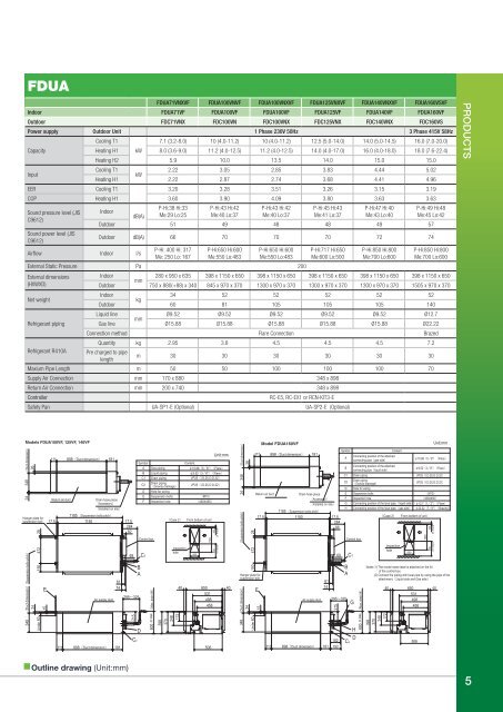
Models FDUA100VF, 125VF, 140VF<br />
Duct dimension<br />
26<br />
348<br />
24<br />
Hanger plate for<br />
suspension bolt<br />
348 Duct dimension Suspension bolts pitch<br />
24<br />
Under 60<br />
150 472 28<br />
15<br />
E<br />
111 898 Duct dimension 181<br />
Return air duct Drain hose piece<br />
Accessory<br />
Installed on site<br />
1185 Suspension bolts pitch<br />
17.5 1150 17.5<br />
284<br />
82<br />
Outline drawing (Unit:mm)<br />
Model FDUM50VF<br />
Air supply duct<br />
61<br />
74<br />
111 898 Duct dimension 181<br />
Note 1 The model name label is attached<br />
on the lid of the control box.<br />
215<br />
C2<br />
Symbol<br />
A Gas piping<br />
B Liquid piping<br />
69 C1<br />
B<br />
A<br />
295 325<br />
D<br />
C1 Drain piping VP25 I.D.25,O.D.32<br />
C2<br />
Drain piping<br />
Gravity drainage<br />
VP25 I.D.25,O.D.32<br />
D Hole for wiring<br />
E Suspension bolts M10<br />
F Inspection hole 450X450<br />
Control box<br />
600 or less Max. drain lift<br />
398<br />
370<br />
248<br />
172<br />
Inspection<br />
hole<br />
40<br />
Unit:mm<br />
Content<br />
15.88 5 8" Flare<br />
9.52 3 8" Flare<br />
Case 2 From bottom of unit<br />
650<br />
1500<br />
600<br />
100<br />
or more or more<br />
650 40<br />
531<br />
498<br />
458<br />
506<br />
Duct dimension<br />
26<br />
348<br />
111<br />
Return air ductDrain hose piece<br />
348 Duct dimension<br />
Suspension bolts pitch<br />
24<br />
24<br />
Under 60<br />
150 472 28<br />
15<br />
Hanger plate for<br />
suspension bolt<br />
E<br />
Model FDUA160VF<br />
898<br />
Duct dimension<br />
181<br />
Air supply duct<br />
111 898 Duct dimension 181<br />
Symbol<br />
B<br />
A<br />
Models FDUM60,71VF<br />
A<br />
B<br />
Control box<br />
C2<br />
Connecting position of the attached<br />
connecting pipe gas side<br />
Connecting position of the attached<br />
connecting pipe liquid side<br />
H<br />
D<br />
Content<br />
Unit:mm<br />
15.88 5 8" Flare<br />
9.52 3 8" Flare<br />
C1 Drain piping VP25 I.D.25,O.D.32<br />
C2<br />
Drain piping<br />
Gravity drainage<br />
VP25 I.D.25,O.D.32<br />
D Hole for wiring<br />
E Suspension bolts M10<br />
Accessory<br />
F Inspection hole 450X450<br />
Installed on site G Connecting position of the local pipe. liquid side 12.7 1 2" Flare<br />
1185 Suspension bolts pitch<br />
H Connecting position of the local pipe. gas side 22.22 7 8" Brazing<br />
17.5 1150 17.5<br />
284<br />
86<br />
Case 2 From bottom of unit<br />
61<br />
74<br />
295 325<br />
G<br />
215<br />
69<br />
182<br />
192<br />
C1<br />
600 or less Max. drain lift<br />
398<br />
370<br />
248<br />
172<br />
Inspection<br />
hole<br />
40<br />
650<br />
650 40<br />
531<br />
498<br />
458<br />
506<br />
1500<br />
600<br />
100<br />
or more or more<br />
Notes 1) The model name label is attached on the lid<br />
of the control box.<br />
(2) Connect the piping with local pipe by using the pipe of the<br />
attachment. Liquid side and Gas side<br />
Products 5