Micro - Mitsubishi Heavy Industries
Micro - Mitsubishi Heavy Industries
Micro - Mitsubishi Heavy Industries

You also want an ePaper? Increase the reach of your titles
YUMPU automatically turns print PDFs into web optimized ePapers that Google loves.
Suspension bolts pitch<br />
M<br />
8<br />
Duct dimension<br />
41<br />
200<br />
39<br />
Model FDUM50VF<br />
Hanger plate for<br />
suspension bolt<br />
28<br />
472<br />
135<br />
Duct dimension<br />
43<br />
170<br />
31<br />
170<br />
31<br />
E<br />
50<br />
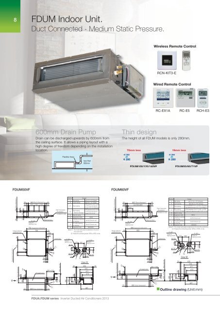
FDUM Indoor Unit.<br />
Duct Connected - Medium Static Pressure.<br />
65 660 Duct dimension 65<br />
46 200 200 200 46<br />
F<br />
12 4<br />
Holes for<br />
tapping screw<br />
Return air duct<br />
18<br />
786 Suspension bolts pitch<br />
750 18<br />
284<br />
81<br />
G<br />
15<br />
600mm Drain Pump<br />
Drain can be discharged upwards by 600mm from<br />
the ceiling surface. It allows a piping layout with a<br />
high degree of freedom depending on the installation<br />
location.<br />
Air supply duct<br />
58<br />
67<br />
55 680 Duct dimension 55<br />
69<br />
B<br />
A<br />
295 325<br />
C2<br />
Drain hose piece<br />
Accessory<br />
Installed on site<br />
Control box<br />
76<br />
600 or less Max. drain lift<br />
D<br />
C1<br />
Flexible hose<br />
Symbol Content<br />
A Gas piping<br />
12.7 1 2" Flare<br />
B Liquid piping<br />
6.35 1 4" Flare<br />
VP20 standard:I.D.20, O.D.26<br />
C1 Drain piping<br />
or VP25 Used with attached<br />
socket:I.D.25, O.D.34 Note 2<br />
C2<br />
Drain piping<br />
Gravity drainage<br />
VP20 standard:I.D.20, O.D.26<br />
or VP25 Used with attached<br />
socket:I.D.25, O.D.34<br />
D Hole for wiring<br />
E Suspension bolts M10<br />
F<br />
Outside air opening<br />
for ducting<br />
150 Knock out<br />
G<br />
Air outlet opening<br />
for ducting<br />
125 Knock out<br />
H Inspection hole 450X450<br />
4 4<br />
Holes for<br />
tapping screws<br />
124<br />
139<br />
170<br />
280<br />
250<br />
175<br />
Notes 1 The model name label is attached on the lid of<br />
the control box.<br />
2 Prepare the connecting socket VP20 or VP25 on site.<br />
View M<br />
FDUA.FDUM series Inverter Ducted Air Conditioners 2013<br />
Hole<br />
30<br />
105<br />
152 262<br />
F G<br />
less than<br />
600mm<br />
Wired Remote Control Wireless Remote Control<br />
RC-EX1A RC-E5 RCH-E3<br />
FduM50VF FduM60VF<br />
4 4<br />
Holes for<br />
tapping screws<br />
90<br />
467<br />
113<br />
170<br />
635 30<br />
510<br />
471<br />
413<br />
Suspension bolts pitch<br />
Thin design<br />
The height of all FDUM models is only 280mm.<br />
H 350<br />
H 280<br />
Model FDUM60VF<br />
Duct dimension<br />
41<br />
200<br />
39<br />
Hanger plate for<br />
suspension bolt<br />
M<br />
28<br />
472<br />
135<br />
31<br />
170<br />
31<br />
E<br />
F<br />
G<br />
170 Duct dimension<br />
43<br />
50<br />
15<br />
55<br />
70mm less 19mm less<br />
FDUM100/125/140VF<br />
880<br />
Air supply duct<br />
Duct dimension<br />
58<br />
67<br />
55<br />
RCN-KIT3-E<br />
Wired Remote Control W<br />
69<br />
295 325<br />
RC-EX1A RC-E5 RCH-E3<br />
B<br />
A<br />
C2<br />
76<br />
600 or less Max. drain lift<br />
D<br />
C1<br />
H 299<br />
H 280<br />
139<br />
170<br />
Hole<br />
280<br />
250<br />
175<br />
FDUM50/60/71VF<br />
Symbol Content<br />
65<br />
46<br />
860 Duct dimension<br />
4 200=800<br />
200<br />
65<br />
46<br />
Drain hose piece<br />
Accessory<br />
Installed on site<br />
A<br />
B<br />
C1<br />
C2<br />
D<br />
Gas piping<br />
Liquid piping<br />
Drain piping<br />
Drain piping<br />
Gravity drainage<br />
Hole for wiring<br />
12.7 1 2" Flare<br />
6.35 1 4" Flare<br />
VP20 standard:I.D.20, O.D.26 or VP25 Used<br />
with attached socket:I.D.25, O.D.34 Note 2<br />
VP20 standard:I.D.20, O.D.26 or VP25<br />
Used with attached socket:I.D.25, O.D.34<br />
E Suspension bolts M10<br />
14 4<br />
Holes for<br />
tapping screw<br />
Return air duct<br />
F<br />
G<br />
H<br />
Outside air opening<br />
for ducting<br />
Air outlet opening<br />
for ducting<br />
Inspection hole<br />
150 Knock out<br />
125 Knock out<br />
450X450<br />
18<br />
986 Suspension bolts pitch<br />
950 18<br />
284<br />
81<br />
Control box<br />
Notes 1 The model name label is attached on the lid of the control box.<br />
2 Prepare the connecting socket VP20 or VP25 on site.<br />
4 4<br />
4 4<br />
Holes for<br />
tapping screws<br />
Holes for<br />
152 262 tapping screws<br />
124<br />
30<br />
105<br />
F<br />
View M<br />
G<br />
467<br />
90<br />
113<br />
170<br />
635 30<br />
510<br />
471<br />
413<br />
Outline drawing (Unit:mm)<br />
Model FDUM50VF