COLUMN JIB CRANE - INSTRUCTIONS FOR USE -
COLUMN JIB CRANE - INSTRUCTIONS FOR USE -
COLUMN JIB CRANE - INSTRUCTIONS FOR USE -

You also want an ePaper? Increase the reach of your titles
YUMPU automatically turns print PDFs into web optimized ePapers that Google loves.
DONATI SOLLEVAMENTI S.r.l.<br />
Via Roma, 55 - 21020 Daverio ( VA )<br />
Tel. (0332) 942611 - Fax. (0332) 948597<br />
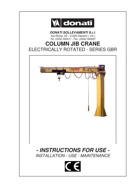
<strong>COLUMN</strong> <strong>JIB</strong> <strong>CRANE</strong><br />
ELECTRICALLY ROTATED - SERIES GBR<br />
- <strong>INSTRUCTIONS</strong> <strong>FOR</strong> <strong>USE</strong> -<br />
INSTALLATION - <strong>USE</strong> - MAINTENANCE
DONATI SOLLEVAMENTI S.r.l. - Via Roma, 55 - 21020 Daverio (VA) - Tel. 0332 942611 - Fax. 0332 948597<br />
INDEX<br />
1. PRELIMINARY IN<strong>FOR</strong>MATION 1<br />
1.1 Contents and use of the manual 1<br />
1.2 Symbols: meaning and use 1<br />
1.3 Co-operation with the user 2<br />
1.4 Conformity with safety regulations 2<br />
1.5 The manufacturer’s responsibility and the warranty 3<br />
2. DESCRIPTION OF THE MACHINE AND TECHNICAL IN<strong>FOR</strong>MATION 4<br />
2.1 The electrically rotated jib crane 4<br />
2.1.1 Intended use - Foreseen use - Designated use 4<br />
2.1.2 The composition of the jib cranes 5<br />
2.1.3 Constraints when installing 6<br />
2.1.4 Criteria of choice and use 6<br />
2.2 Technical information and service conditions 7<br />
2.2.1 Safety reference list 7<br />
2.2.2 Protection and insulation of electrical parts 7<br />
2.2.3 Electrical power supply 7<br />
2.2.4 Environment conditions of use 7<br />
2.2.5 Noise - Vibrations 7<br />
2.2.6 Characteristics and technical data - Weights - Reactions on constraints 8<br />
3. SAFETY AND ACCIDENT PREVENTION 11<br />
3.1 Qualifications of qualified operators 11<br />
3.2 General safety regulations 12<br />
3.3 Safety symbols 12<br />
3.4 Warning about remaining risks 14<br />
3.5 Safety measures and instructions 15<br />
3.5.1 Control devices 15<br />
3.5.2 Safety and emergency devices 16<br />
3.5.3 Warning and signalling devices - List of labels 17<br />
4. HANDLING - INSTALLATION - PUTTING INTO OPERATION 18<br />
4.1 General notes at delivery 18<br />
4.2 Packing, transportation and handling 19<br />
4.2.1 Standard packing 19<br />
4.2.2 Transportation 19<br />
4.2.3 Handling 20<br />
4.2.4 Removing the packing 20<br />
4.3 Installation of the jib crane 21<br />
4.3.1 Duties and responsibilities of the installer 21<br />
4.3.2 Preparing the place of installation 22<br />
4.3.3 Assembly of the column 23<br />
4.3.4 Assembly of the bracket 25<br />
4.3.5 Assembly of the trolley/hoist 27<br />
4.3.6 Assembly of the electric system 27<br />
4.3.6.1 Putting the rotating limit switch into operation 29<br />
4.3.7 Electrical wirings – Version with two electrical control panels 30<br />
4.3.7.1 Electrical wirings – Version with one electrical control panel 31<br />
4.4 Putting the machine into operation 33<br />
4.4.1 Preliminary operations – Adjustments and test runs 33<br />
4.4.2 Inspection of the jib crane – Suitability for use 34<br />
4.5 Out of service 36<br />
4.5.1 Storage and conservation of parts 36<br />
4.5.2 Reuse after storage 36<br />
II<br />
Pag.
DONATI SOLLEVAMENTI S.r.l. - Via Roma, 55 - 21020 Daverio (VA) - Tel. 0332 942611 - Fax. 0332 948597<br />
INDEX<br />
5. FUNCTIONING AND <strong>USE</strong> OF THE <strong>JIB</strong> <strong>CRANE</strong> 37<br />
5.1 Functions of the jib crane 37<br />
5.1.1 Intended use - Foreseen use - Designated use 37<br />
5.1.2 Permitted loads, loads not permitted 38<br />
5.1.3 Lifting accessories 38<br />
5.2 Operating conditions 39<br />
5.2.1 Operating environment 39<br />
5.2.2 Danger zones and people exposed to risk 39<br />
5.2.3 Illumination of the work area 40<br />
5.2.4 The operator 40<br />
5.2.5 The lifting capacity of the jib crane 40<br />
5.2.6 Manoeuvres: lifting, trolley traverse and arm rotation 41<br />
5.2.7 Safety devices 42<br />
5.3 Setting up - Starting the jib crane 42<br />
5.4 Switching off at the end of use 42<br />
5.5 Criteria and precautions of use 43<br />
5.6 Constraints of use 46<br />
5.6.1 Use not intended and not allowed - Foreseeable and unforeseeable<br />
inappropriate use<br />
46<br />
6. MAINTENANCE OF THE <strong>JIB</strong> <strong>CRANE</strong> 51<br />
6.1 Safety precautions 51<br />
6.2 The qualifications of maintenance staff 53<br />
6.3 Maintenance plan 56<br />
6.3.1 Daily and periodical maintenance 56<br />
6.3.2 Frequency and deadlines for maintenance work 57<br />
6.3.3 Check of efficiency of parts and components 58<br />
6.3.4 Cleaning and lubrication of the jib crane 62<br />
6.4 Adjusting and regulating 63<br />
6.4.1 Adjusting the rotation brake of the crane arm 63<br />
6.5 Breakdowns and solutions 65<br />
6.5.1 Main types of failure 65<br />
6.5.2 Breakdowns and possibile solutions 66<br />
6.5.3 Authorised staff for intervention in case of breakdown 66<br />
6.5.4 Putting out of service 66<br />
6.6 Dismantling, disposal and scrapping 67<br />
7. SPARE PARTS 67<br />
8. THE CHECKS REGISTER 68<br />
III<br />
Pag.
DONATI SOLLEVAMENTI S.r.l. - Via Roma, 55 - 21020 Daverio (VA) - Tel. 0332 942611 - Fax. 0332 948597<br />
Dear customer,<br />
LETTER ON DELIVERY<br />
• We thank you for having chosen a DONATI jib crane and we are happy to provide you with this<br />
technical publication which aims at achieving the maximum productivity of the machine in the<br />
safest way possible.<br />
• DONATI SOLLEVAMENTI S.r.l. produces jib cranes and relevant accessories, using a QUALITY<br />
SYSTEM in accordance with the UNI EN ISO 9001 regulations: 2000 certified by ICIM with N°<br />
114.<br />
• This documentation, originally written in Italian, takes into consideration the EN 292 norm - 1° part<br />
point 3.20 and 2° part point 5 and has been created in compliance with the requirements 1.7.4<br />
and 4.4.2. of the Directive 98/37CE ex 89/392CEE and successive amendments.<br />
• We would like you to read this manual carefully and to provide the staff who will work the jib crane<br />
with a copy of it.<br />
Example certification CISQ-ICIM<br />
IV<br />
DONATI SOLLEVAMENTI S.r.l.<br />
Example certification IQ Net
DONATI SOLLEVAMENTI S.r.l. - Via Roma, 55 - 21020 Daverio (VA) - Tel. 0332 942611 - Fax. 0332 948597<br />
1.1 Contents and use of the manual<br />
1. - PRELIMINARY IN<strong>FOR</strong>MATION<br />
This technical publication, identified by the code MAN 092001G, refers to “360° electrically rotated jib cranes -<br />
series GBR”, built and put on the market by the company:<br />
1<br />
DONATI SOLLEVAMENTI S.r.l.<br />
Via Roma, 55 - 21020 Daverio (VA)<br />
Tel. 0332.942611 - Fax. 0332.948597<br />
It refers to their “intended use”, to their technical functional and performance characteristics and to the relevant<br />
installation, use and maintenance instructions. It is intended for:<br />
• the supervisor of the factory, workshop, building site<br />
• the staff in charge of transporting, handling and installation of the equipment<br />
• the operators of the jib crane<br />
• the maintenance staff<br />
This manual must be kept by the person in charge of the above mentioned duties in a suitable place, so that it is<br />
always available for consultation and kept in the best possible state.<br />
If the manual is lost or becomes unusable, replacement documentation should be requested directly from the<br />
manufacturer by quoting the code of this manual.<br />
The manufacturer retains the material and intellectual rights of this publication and<br />
forbids the divulgation and duplication, even partial, without prior written permission.<br />
Copyright© 2007 by DONATI SOLLEVAMENTI S.r.l.<br />
1.2 Symbols: meaning and use<br />
In this manual certain symbols are used to focus the reader’s attention and underline some particularly important<br />
aspects of the subject.<br />
The following table shows the list and meaning of the symbols used in the manual.<br />
SYMBOL MEANING EXPLANATION, ADVICE, NOTES<br />
• Indicates a danger with risk of accident, possibly fatal.<br />
• Failure to follow the attached instructions can cause a situation of<br />
Danger serious danger for the safety of the operator and for people in the<br />
vicinity!<br />
• Follow the instructions scrupulously !<br />
• Represents a warning note of attention of possible deterioration of the<br />
Warning jib or of a personal object of the operator.<br />
• Important warning which requires one’s utmost care.<br />
Warning/Note • Indicates a warning or a note about key functions or useful<br />
information.<br />
• Visual • A printed eye can indicate to the reader that:<br />
observation a) He should proceed to a visual observation.<br />
• Action to be<br />
taken<br />
b) He should proceed to the operating sequence.<br />
c) It is necessary to take a reading, to check a signal, etc.
DONATI SOLLEVAMENTI S.r.l. - Via Roma, 55 - 21020 Daverio (VA) - Tel. 0332 942611 - Fax. 0332 948597<br />
1.3 Co-operation with the user<br />
This manual reflects the configuration of the machine at the time the machine was put on the market. Any change<br />
to the manual, a copy of which will be sent to the customer by the manufacturer, shall be kept together with the<br />
manual.<br />
The manufacturer is willing to supply its customers with any additional information they may require, and<br />
welcomes any suggestions aimed at improving the manual so that it corresponds better to the customer’s needs.If<br />
the jib crane is no longer to be used the main user is invited to deliver, with the hoist, this manual and the relevant<br />
documentation enclosed with it (declarations, schemes, control register etc.).<br />
1.4 Conformity with safety regulations<br />
The jib crane was designed and produced following the “Essential Safety Requirements” of Enclosure I of the<br />
Community Directive 98/37/EC ex 89/392/EEC and successive amendments 91/368/EEC, 93/44/EEC and<br />
93/68/EEC, denominated Machines Directive, transposed into Italian legislation with DPR N° 459 of 24.07.96.<br />
Regarding what was stated in Enclosure II of the Directive 98/37/CE, the crane can be put on the market in the<br />
following ways:<br />
A) Complete, or capable of functioning independently, having the CE Mark and the EC Declaration of<br />
Conformity - Enclosure II A.<br />
B) Incomplete as destined to be incorporated in another machine and/or to be completed (i.e.: hoist) by the<br />
Customer.<br />
In this case, in accordance with Article 4 - paragraph 2 of the Directive 98/37/CE, the jib crane<br />
does not carry the CE Mark and is supplied with the Declaration of the Manufacturer - Enclosure II B.<br />
example CE Declaration CE of Conformoty<br />
Enclosure II A<br />
2<br />
example Declaration by the Manufacturer<br />
Enclosure II B<br />
Besides the jib cranes series GBR are conform with the following directives :<br />
• Low Voltage Directive (DBT) 73/23/CEE, transposed in the Italian legislative system with the Law N°<br />
791/77 modified with the D.Lgs N° 626/96 and with the D.Lgs. N° 277/97.<br />
• Electromagnetic Compatibility Directive (EMC) 89/336/CEE transposed in the Italian legislative<br />
system with D.Lgs. N° 476/92 modified with D.Lgs. N° 615/96.
DONATI SOLLEVAMENTI S.r.l. - Via Roma, 55 - 21020 Daverio (VA) - Tel. 0332 942611 - Fax. 0332 948597<br />
1.5 The manufacturer’s responsibility and the warranty<br />
With reference to the contents of this manual DONATI SOLLEVAMENTI S.r.l. declines any responsibility in<br />
case of:<br />
• use of the jib crane contrary to the national safety and accident prevention laws<br />
• erroneous choice of the building site or buildings in which the jib crane is to be operated<br />
• voltage and power supply faults<br />
• lack of or erroneous observation of the instructions supplied in this manual<br />
• non-authorised modifications to the machine<br />
• use (of the machine) by untrained or unsuitable staff<br />
To be able to use the warranty, the certification of which is shown below, the Customer must scrupulously follow<br />
the instructions indicated in this manual, and in particular:<br />
• always work within the use limits of the jib crane<br />
• always carry out constant, diligent maintenance<br />
• appoint operators of proven capability, who have been adequately trained for the job to use the machine<br />
• use solely original spare parts indicated by the manufacturer<br />
• The intended use and configurations of the hoist are the only ones allowed. Do not<br />
try to use the hoist disregarding the supplied instructions.<br />
• The instructions in this manual do not replace but add to the obligations regarding<br />
the current legislation for accident prevention standards.<br />
CERTIFICATE OF WARRANTY<br />
• DONATI SOLLEVAMENTI S.r.l. is the “Manufacturer” of the column-mounted jib crane of the<br />
series GBR the subject of this technical publication.<br />
• DONATI SOLLEVAMENTI S.r.l. carries out the check on manufacturing regarding the<br />
“Qualitysystem” of the company by ICIM with N° 114, according to the standard UNI EN ISO<br />
9001: 2000<br />
All jib cranes, series GBR, are covered by the following warranty formula :<br />
1. The warranty of the machine lasts for 36 months from delivery, attested to by the date of the invoice, taking into account the<br />
specifications and exclusions outlined as will follow and except for different explicit agreements between the parties. It is<br />
subject to the reporting by registered letter, within 8 days of the discovery of faults and the recognition of the existence of<br />
these by DONATI SOLLEVAMENTI S.r.l.<br />
2. The warranty covers exclusively the resulting faulty parts from causes attributable to DONATI SOLLEVAMENTI S.r.l. and<br />
includes the replacement or repair of the faulty part excluding the dismantling, reassembly and despatch costs. The parts<br />
which DONATI SOLLEVAMENTI S.r.l. recognizes as faulty will have free despatch from the factory situated in Daverio (VA).<br />
3. For components provided by third parties (commercial, electrical, mechanical and electromechanical components) the<br />
prevailing warranty conditions are those of the respective manufacturers.<br />
4. Parts damaged during transportation or handling, as well as those subject to normal wear and tear (e.g. gaskets) and/or to<br />
perishing by atmospheric or environmental agents are excluded from the warranty. Damage from lack of or insufficient or<br />
wrong maintenance, from unskilful use, improper use, use not allowed or not intended, from non-authorised modifications or<br />
repairs, from tampering and from interventions by unqualified staff or not as explained in the manufacturer’s instructions are<br />
excluded from the warranty.<br />
5. The validity of the warranty is subject to the correct installation, periodical checks and maintenance as in the instruction<br />
manual for “installation, use and maintenance”, which accompanies the machine, as well as the diligent annotations in the<br />
enclosed “control register” of all the maintenance work, checks, verifications, and periodical inspections.<br />
6. The replacement of faulty parts does not imply the renewal of the period of warranty of the whole machine. DONATI<br />
SOLLEVAMENTI S.r.l. is in any case exonerated from any obligation to give compensation to any claim and the Purchaser<br />
renounces any claim for costs or damages, direct or indirect, also to third parties, due to any standstill.<br />
7. The warranty is lost if non-original DONATI spare parts or spare parts not prescribed by DONATI are used.<br />
8. For any dispute the Foro Giudiziario (Law Courts) of Varese is exclusively competent.<br />
3<br />
DONATI SOLLEVAMENTI S.r.l.
DONATI SOLLEVAMENTI S.r.l. - Via Roma, 55 - 21020 Daverio (VA) - Tel. 0332 942611 - Fax. 0332 948597<br />
2. - DESCRIPTION OF THE MACHINE AND TECHNICAL<br />
IN<strong>FOR</strong>MATION<br />
2.1 The electrically rotated jib cranes<br />
2.1.1 Intended use – Foreseen use – Designated use<br />
The jib cranes, electrically rotated, “Column” version - series GBR, are intended to be fixed to the ground and are<br />
produced to move goods within the plant, in outdoor squares or for services of big operating units.<br />
The jib cranes lifting a load vertically, by means of the hook of the lifting block , generally made using appropriate<br />
accessories for such an operation; moving the load with a trolley which runs along the radial axis of the arm and<br />
slave, with electrically rotation, a circular area delineated by the rotation radius of the jib.<br />
The rotation of the arm of the crane, which is mounted on a rotating thrust bearing, is ensured via a motoreducer.<br />
The circular area served by the arm can, according to necessity, be limited by electrical limit switches, or allow<br />
continual rotation, without end, of the arm itself in both directions by a collector ring.<br />
The electrically rotated jib cranes serie GBR have then three functions:<br />
• lifting the load, generally made by an electric chain or rope hoist<br />
• moving the load with the aid of an electric trolley which runs along the arm of the crane<br />
• rotating a load around the constraint axis of the arm mounted on a rotating thrust bearing.<br />
§ All the movements are done with a push button panel.<br />
Legenda:<br />
1. column<br />
2. base plate<br />
3. thrust bearing<br />
4. motoreducer<br />
5. rotating arm<br />
6. lifting unit<br />
7. electric equipment<br />
8. push button panel<br />
fig.1<br />
4
DONATI SOLLEVAMENTI S.r.l. - Via Roma, 55 - 21020 Daverio (VA) - Tel. 0332 942611 - Fax. 0332 948597<br />
2.1.2 The composition of the jib crane<br />
Column:<br />
• Made of press-forged steel section welded to the tubular structure with polygonal section it allows a high<br />
rigidity and stability; it is fixed with a base plate and a system of bolts and log bolts. The upper part is fitted<br />
with a flange for fixing the rotation thrust bearing.<br />
Rotating arm:<br />
• This is formed by a supporting girder and, in relation to the lifting capacity and/or the jib length, can be made<br />
with an H beam or with a box beam designed to guarantee the maximum flexotorsional stability. In the<br />
construction of the box beam high quality section steel is used and welding carried out with continuous line<br />
procedure to censure optimal safety conditions and operative reliability of the crane.<br />
Rotation mechanisms:<br />
• Base bearing or thrust bearing, able to support both axial pushes, due to vertical forces and the tilting<br />
momentum due to the movement.<br />
• Motoreducer, fitted on the arm, fitted with a self-braking motor with progressive start-up and braking where<br />
the sprocket, keyed on the slow shaft, fits together with the internal toothing of the thrust bearing to which it<br />
gives movement.<br />
Electric power supply:<br />
• Made for powering the hoist and trolley which runs along the arm of the crane as well as to power the rotation<br />
motoreducer.<br />
The electric power supply includes:<br />
• The electrical panel made of press-forged sheet. It contains the contactors and the timers to control all<br />
the movements of the crane, as well as protection fuses against short circuits. The control circuits are low<br />
voltage (48 V). A connection terminal box ensures simplicity and safety of cabling of the cables relative to<br />
all the external functions making any inspection easy to perform.<br />
• The electrical line to power the trolley-hoist formed of flat flexible multipolar cables festooned on the<br />
trolleys which slide inside a channel section.<br />
• The push-button control panel, with a shockproof thermoplastic casing, sliding, along the crane girder,<br />
via trolleys inside a channel section using festooned flexible multipolar cable. It is supported by a self<br />
supported round multipolar cable. It is generally fitted with a connector with fast connectors and obliged<br />
polarity, to make assembly and replacement easier.<br />
• Acoustic alarm, when necessary, controlled using an “alarm” button it serves the function of acoustic<br />
warning to indicate any dangerous situations during handling.<br />
• Electric safety limit switches on the movements of rotation installed to limit the rotation field of the arm<br />
of the crane. They act on the low voltage auxiliary circuits.<br />
• Rotating collector ring. It is installed when the arm of the crane is free from obstacles in every point of<br />
its rotation and the arm itself is required to rotate continuously in both directions.<br />
Foundation frame with log bolts:<br />
• This is supplied on request for the fixing of the column itself to the base.<br />
Finish:<br />
• The protection of the steel structures from atmospheric and environmental agents (powders, gas,etc.) is<br />
guaranteed by the treatments which use yellow enamel paint, subject to preparation of the surfaces with<br />
metallic sanding of SA grade.<br />
On request special anticorrosive paint is available.<br />
Lifting and translation unit:<br />
• The electrically rotated jib cranes serie GBR can be equipped with hoist with the relevant electric trolley.<br />
5
DONATI SOLLEVAMENTI S.r.l. - Via Roma, 55 - 21020 Daverio (VA) - Tel. 0332 942611 - Fax. 0332 948597<br />
The conception and construction of the jib cranes GBR:<br />
• The jib cranes, electrically rotated, column version - serie GBR, are designed according to the conception of<br />
the modular components which put together in relation to commercial needs, as well as the standard models<br />
always available from the warehouse, allow the rapid economical realisation of numerous normalised and<br />
special executions.<br />
• The base, column, bracket and arms components, thanks to their extreme compactness are assembly<br />
together, so as to guarantee the maximum use of the hook run and, thanks to the minimal side clearance allow<br />
an optimal use of the area in which the jib crane operates.<br />
• The construction uses the most advanced technology which is based on production processes of high<br />
industrialization and allows the realization, using economies of scale, of totally reliable and technically<br />
innovative machines. The high level of quality is guaranteed and controlled by the company quality system<br />
according to the UNI EN ISO 9001: 2000.<br />
2.1.3 Constraints when installing<br />
The jib cranes “column” version - series GBR, are intended to be fixed to the round, the column is selfsupporting<br />
and can be fixed to the round using log bolts, on a foundation plinth.<br />
• The user MUST check, directly or using specialised staff, the suitability of the<br />
surfaces to be fixed on. These surfaces must guarantee the stability and safety of<br />
the crane in all its working conditions, supporting the lifting operations and the<br />
dynamic effects of the tilting momentum and of the type and speed of lifting.<br />
2.1.4 Criteria of use and conditions of use<br />
The necessary indispensable conditions to obtain the full functional responsiveness of the jib crane for the service<br />
it is intended, as well as its optimal and lasting functioning, are in the correct choice of the model of machine. This<br />
choice must be made in relation to the real service performance required as well as the environmental conditions<br />
in which the jib crane will have to operate.<br />
The parameters which must be carefully considered in the choice of jib crane are :<br />
• The lifting capacity: this must be determined by the weight of the maximum load to be lifted and must never be<br />
less than this weight.<br />
• The functional dimensions: the height of the sliding girder of the trolley which determines the hook run of the<br />
hoist and the range must be selected so as to guarantee the functional coverage of the space to be used<br />
considering the surrounding clearance.<br />
• The nature of the load: the nature of the load determines for its positioning the choice of the speeds of<br />
movement (lifting and translating) suited to the task. In some cases it is indispensable to use two-speed hoists<br />
with a slow positioning speed.<br />
• The area to be used in: the jib crane features in its conception intrinsic high elasticity which becomes even<br />
more evident when it is used for moving loads close to the maximum load and/or with prevalent localisation in the<br />
ends of the arm.<br />
• The environment to be used in: the jib cranes are intended for service indoors and/or in a covered area,<br />
sheltered from bad weather and away from wind. In the case of use outdoors adequate steps must be taken in<br />
relation to the surface treatment (sanding, varnishing) as well as a system of stopping brake.<br />
6
DONATI SOLLEVAMENTI S.r.l. - Via Roma, 55 - 21020 Daverio (VA) - Tel. 0332 942611 - Fax. 0332 948597<br />
2.2 Technical information and service conditions<br />
2.2.1 Safety reference list<br />
In the planning and construction of the electrically rotated jib cranes - series GBR, the following standards and<br />
principal technical regulations have been taken into account:<br />
• EN - 292 parts: 1a - 2 a "Safety of machines".<br />
• EN - 954 - 1 “ Parts of the control system correlated to safety “.<br />
• EN - 60204 - 1 "Safety of electrical equipment of machines- General rules".<br />
• EN - 60204 - 32 "Safety of electrical equipment of lifting machines".<br />
• EN - 60439 - 1 " Control panels in low voltage ".<br />
• EN - 60529 “Degrees of IP protection”<br />
• ISO 4301 "Classification of lifting apparatus"<br />
• UNI 7670 "Calculation of the mechanisms of lifting apparatus"<br />
• FEM 1.001/98 “Calculation of lifting apparatus”<br />
• FEM 9.511/86 “Classification of mechanisms”<br />
• FEM 9.683/95 " Choice of lifting and moving motors"<br />
• FEM 9.755/93 "Periods of safe work"<br />
• FEM 9.941/95 " Symbology of controls ".<br />
2.2.2 Protection and insulation of electrical parts<br />
• Rotation motor: Protection IP54 (motors) - IP23 (brakes); Insulation class "F"<br />
• Electrical panel: Protection IP55 – Maximum power of insulation 1500 V<br />
• Push-button panel: Protection IP65 – Maximum tension of insulation 500 V<br />
• Collector: Protection IP65 – Maximum power of insulation 600 V<br />
• Rotation limit switch: Protection IP65 – Maximum power of insulation 300 V<br />
• Cables : CEI 20/22 – Maximum power insulation 450/750 V<br />
2.2.3 Electrical power supply<br />
• The electrical jib cranes are designed to be powered with alternate electric power three phase of: 400 V<br />
according IEC 38-1.<br />
2.2.4 Environment conditions of use<br />
• Temperature of use: minimum –10° C; maximum +40° C<br />
• Maximum relative humidity:80%<br />
• Maximum altitude 1000 m – above sea level<br />
• The machine must be placed in a well-ventilated place, free from corrosive vapours (acid vapours, saline<br />
clouds, etc).<br />
• It is forbidden to use the machine in an explosive environment or one which is potentially<br />
so, or where the use of flameproof equipment is prescribed.<br />
• It is necessary to allocate sufficient working space to ensure the safety of the operator and<br />
of the maintenance staff.<br />
2.2.5 Noise - Vibrations<br />
• The level of acoustic pressure emitted by the rotation motoreducer is always lower than 85 dB (A).<br />
• The vibrations produced by the jib crane, during the manual rotation of the arm, are practically nil and<br />
in any case not dangerous for the health of the staff who operate them.<br />
• Excessive noise or vibration can be caused by a fault which must be immediately notified and<br />
eliminated so as not to compromise the reliability of the jib crane.<br />
7
DONATI SOLLEVAMENTI S.r.l. - Via Roma, 55 - 21020 Daverio (VA) - Tel. 0332 942611 - Fax. 0332 948597<br />
2.2.6 Characteristics and technical data - Weights - Reactions on constraints<br />
Column jib crane - Rotation 360°<br />
Jib crane GBR with electric wire rope hoist DRH: Jib crane GBR with electric chain hoist DMK:<br />
K2 = K1+(C+I1-S3)* referring to fixed mechanical limit switch K2 = K1+(M/2)*referring to fixed mechanical limit switch<br />
K3 = (C+S3)* referring to fixed mechanical limit switch K3 = (M/2)* referring to fixed mechanical limit switch<br />
I* e C2* = (*) See commercial catalogne for DRH hoists I* = (*) See commercial catalogne for DMK hoists<br />
8
DONATI SOLLEVAMENTI S.r.l. - Via Roma, 55 - 21020 Daverio (VA) - Tel. 0332 942611 - Fax. 0332 948597<br />
9
DONATI SOLLEVAMENTI S.r.l. - Via Roma, 55 - 21020 Daverio (VA) - Tel. 0332 942611 - Fax. 0332 948597<br />
BASE PLATES,FOUNDATION FRAMES <strong>FOR</strong> GBR SERIES <strong>COLUMN</strong>-MOUNTED <strong>CRANE</strong><br />
Size of jib crane 2 3 4 5 6<br />
Base plate and foundation frame (mm) ���� C 750 860 910 1100 1220<br />
S1 20 25 30 35 40<br />
S2 10 10 10 10 10<br />
X 199 230 241 185 215<br />
Y 281 325 341 320 350<br />
∅ 1 27 33 39 39 39<br />
∅ 2 25 31 37 37 37<br />
r 150 170 180 220 240<br />
Anchorage bolts (mm) ∅ T M 24 x 3 M 30 x 3.5 M 36 x 4 M 36 x 4 M 36 x 4<br />
LT 600 700 800 800 800<br />
ST 90 105 125 130 135<br />
Camping couplet for the logbolts (Nm) 350 680 1200 1200 1200<br />
Weight of the frame with logbolts (kg) 34.5 52.5 80 113 120<br />
Foundation plinth (mm) ���� L 2500 3000 3200 4000 4200<br />
H 1150 1300 1300 1300 1300<br />
Jib crane max.weight (kN) Q 1 79 126 183 183 183<br />
Maximum tilting momentum (kNm) Mf 179 270 335 649 788<br />
The dimensions of the plinths are purely indicative !<br />
The plinth must be dimensioned by expert, qualified technicians considering the real consistency of the groundand the maximum pressure allowed by this.<br />
10
DONATI SOLLEVAMENTI S.r.l. - Via Roma, 55 - 21020 Daverio (VA) - Tel. 0332 942611 - Fax. 0332 948597<br />
3. - SAFETY AND ACCIDENT PREVENTION<br />
The electrically rotated jib cranes - series GBR and accessories have been designed and manufactured using the<br />
most modern technical knowledge and can be used safely.<br />
The dangers for persons working with them can be totally eliminated and/or notably reduced only if the jib crane is<br />
used by authorised staff who are appropriately trained and sufficiently prepared in accordance with the instructions<br />
in this documentation.<br />
THE STAFF ARE RESPONSIBLE <strong>FOR</strong> THE FOLLOWING OPERATIONS:<br />
Completing the jib crane with any missing parts and installing it (e.g. hoist, electric controls, fixing accessories,<br />
etc.) Setting up the crane and, in any case, the managing of its functioning;<br />
Inspections and checks of the crane and its components, before starting up the machine, during its functioning or<br />
also after it stops.<br />
Maintenance of the crane, the checking and the repair and/or replacement of its components.<br />
Staff must be completely informed about the potential dangers in the execution of their duties, both regarding the<br />
functioning and the correct use of safety measures available on the machine.<br />
These staff must, moreover follow the safety regulations carefully, as described in this chapter, to prevent<br />
dangerous situations occurring.<br />
3.1 Qualifications of qualified operators<br />
The following table is designed to define more clearly the field of intervention and the consequent assumption of<br />
responsibility of every single OPERATOR, given their specific training and qualification obtained. It shows with a<br />
pictogram the professional figures necessary for every kind of intervention.<br />
PICTOGRAM<br />
OPERATOR<br />
MECHANICAL MAINTENANCE<br />
OFFICER<br />
ELECTRICAL MAINTENANCE<br />
OFFICER<br />
MECHANICAL TECHNICIAN<br />
ELECTRICAL TECHNICIAN<br />
11<br />
OPERATOR PROFILE<br />
Jib crane operator:<br />
Persons qualified to perform simple tasks, that is the driving of the crane<br />
by use of the controls and the loading and unloading of the materials to<br />
OPERATOR be moved.<br />
Mechanical maintenance officer:<br />
Qualified persons able to intervene on the crane in normal conditions, to<br />
carry out normal adjustments to the mechanisms, ordinary maintenance<br />
checks and mechanical repairs.<br />
Electrical maintenance officer:<br />
Qualified persons able to intervene on the crane in normal conditions<br />
and for normal interventions of an electrical nature, adjustments,<br />
maintenance and repairs. This person can operate with the presence<br />
of current in the control boards.<br />
Mechanical technician:<br />
Qualified technician authorised to carry out operations of a complex and<br />
exceptional mechanical nature.<br />
Electrical technician:<br />
Qualified technician authorised to carry out operations of a complex and<br />
exceptional electrical nature.
DONATI SOLLEVAMENTI S.r.l. - Via Roma, 55 - 21020 Daverio (VA) - Tel. 0332 942611 - Fax. 0332 948597<br />
3.2 General safety regulations<br />
Before putting the jib crane into service it is necessary:<br />
• to read the technical documentation carefully;<br />
• to find out about the functioning and the positioning of the emergency stopping devices;<br />
• to know which safety devices are installed on the jib crane and where they are positioned;<br />
Some activities to be carried out on functioning components (e.g. replacing a hoist chain) expose the operators to<br />
situations of grave danger, so it is necessary to adhere strictly to the following rules:<br />
• Staff must be authorised and properly trained regarding the operating procedures to follow, the dangerous<br />
situations that could occur and the correct methods for preventing them.<br />
• If ,exceptionally, staff have to deactivate completely or partially, open or remove the protective covers to allow a<br />
particular specialised technical intervention of maintenance, inspection or repair to be carried out, it will be their<br />
precise duty to put back immediately the relevant protective covers at the end of the intervention. The staff in<br />
charge must make sure that at the end of the intervention mechanical parts, tools or other devices used are not<br />
forgotten on the crane, since this may provoke damages or malfunctions.<br />
• Staff in charge of maintenance, inspection and repair operations must use all the necessary and possible<br />
preventive safety measures before beginning work for their own safety, and in particular, they must check that:<br />
• The jib crane is deactivated and the appropriate preventive measures have been taken (signs, blocking<br />
controls etc.) to avoid the accidental starting. To allow the execution of a technical intervention on an<br />
electric device, in the presence of voltage current, pay the maximum attention and operate with extreme<br />
caution.<br />
3.3 Safety symbols<br />
In the manual and in danger zones, signs and pictograms are used to underline or bring attention to potentially<br />
dangerous situations due to residual risks, or to actions which must be performed obligatorily according to the<br />
safety procedures shown in this manual.<br />
SIGNS <strong>USE</strong>D TO INDICATE DANGERS<br />
SIGN MEANING<br />
DANGER PARTS WITH LIVE TENSION<br />
GENERAL DANGER<br />
DANGER OF CRUSHING<br />
DANGER OF ENTANGLEMENT<br />
DANGER FROM SUSPENDED LOADS<br />
Signals the presence of live voltage and is fixed to electrical<br />
equipment and on any structure which has live electrical voltage<br />
inside.<br />
Warning: general danger<br />
(accompanied by diagram which indicates what kind of<br />
danger)<br />
Warning danger of crushing due to mechanical machine-parts<br />
in movement.<br />
Warning danger of entanglement or dragging from machineparts<br />
in motion (chains, wheels, etc.)<br />
Warning danger from suspended loads being moved by the<br />
crane.<br />
12
DONATI SOLLEVAMENTI S.r.l. - Via Roma, 55 - 21020 Daverio (VA) - Tel. 0332 942611 - Fax. 0332 948597<br />
SIGNS <strong>USE</strong>D TO INDICATE BANS<br />
SIGN MEANING<br />
IT IS <strong>FOR</strong>BIDDEN TO REMOVE THE<br />
PROTECTION<br />
IT IS <strong>FOR</strong>BIDDEN TO MANOEUVRE<br />
It is forbidden to remove the safety devices on a machine in<br />
motion.<br />
It is forbidden to carry out manoeuvres during maintenance<br />
phases of moving machine-parts.<br />
SIGNS <strong>USE</strong>D TO INDICATE OBLIGATIONS<br />
SIGN MEANING<br />
CONSULT THE MANUAL<br />
GLOVES MUST BE WORN<br />
HELMETS MUST BE WORN<br />
PROTECTIVE FOOTWEAR MUST BE<br />
WORN<br />
SAFETY HARNESSES MUST BE WORN<br />
CHECK LIFTING OF THE MACHINE-<br />
PARTS<br />
Consult the manual when you see, preceding or positioned<br />
inside an indication (instructions, settings, maintenance,<br />
etc.)<br />
It is compulsory to wear protection gloves.<br />
It is compulsory to wear safety helmets.<br />
It is compulsory to wear non-slip protective footwear.<br />
It is compulsory to wear safety harnesses in operations at a<br />
height with the risk of falling down.<br />
The preventive checking of wire ropes, hooks, safety<br />
harnesses and accessories used for lifting and<br />
manoeuvring is compulsory.<br />
SIGNS <strong>USE</strong>D <strong>FOR</strong> SAFETY INDICATIONS<br />
SIGN MEANING<br />
AUXILIARY ILLUMINATION<br />
For the interventions indicated the use of auxiliary<br />
illumination is recommended.<br />
13
DONATI SOLLEVAMENTI S.r.l. - Via Roma, 55 - 21020 Daverio (VA) - Tel. 0332 942611 - Fax. 0332 948597<br />
3.4 Warning about remaining risks<br />
Having carefully considered the possible dangers in all the operating phases of the jib crane, necessary measures<br />
have been taken to eliminate, as far as possible, risks to the operators and/or limit or reduce the risks derived<br />
from dangers not totally eliminable at source. Nevertheless, despite all the precautions taken, the following<br />
remaining risks which are eliminable or reducible with the relevant prevention activities, still exist:<br />
RISKS DURING <strong>USE</strong><br />
DANGER / RISK BAN / WARNING OBLIGATION / PREVENTION<br />
Risk from danger of crushing<br />
during the manoeuvring of loads<br />
suspended when the operator or<br />
other staff are in relevant<br />
zones/areas in the path of the<br />
load.<br />
Risk from dangers of<br />
entanglement and/or crushing<br />
after contact with the rotating<br />
arm and/or moveable parts of<br />
the trolley/hoist.<br />
• It is forbidden to lift loads<br />
while people are passing<br />
through the related<br />
manoeuvre area.<br />
• It is forbidden to transit,<br />
remain or manoeuvre under<br />
the suspended load.<br />
• Warning! Exposure to the<br />
parts in motion can create<br />
dangerous situations.<br />
• It is forbidden to touch the<br />
crane arm and the trolley/hoist<br />
in motion or to stand in their<br />
path.<br />
RISKS DURING MAINTENANCE<br />
14<br />
• The operator must follow the<br />
indications to obtain maximum<br />
safety by observing the<br />
indications in this manual.<br />
• Obligation to do periodical<br />
checks of the wire rope and the<br />
hook.<br />
• Obligation to use protective<br />
gloves during the phases of<br />
positioning of the harness and<br />
when moving the load by<br />
pushing it.<br />
DANGER / RISK BAN / WARNING OBLIGATION / PREVENTION<br />
Risk from danger of<br />
electrocution electric shock<br />
during maintenance of electrical<br />
equipment without having<br />
deactivated the electric power<br />
supply<br />
Risk from crushing in case of<br />
contact with the rotating arm<br />
during braking.<br />
• It is forbidden to intervene on<br />
electrical equipment before<br />
having switched off the jib<br />
crane from the electric power<br />
line<br />
• Warning! Exposure to the<br />
parts in motion can create<br />
dangerous situations.<br />
• Entrust electrical maintenance<br />
operations to qualified staff.<br />
• Carry out checks on electrical<br />
equipment prescribed in the<br />
manual.<br />
• Entrust wire rope replacement<br />
operations to qualified<br />
maintenance staff.<br />
• Obligation to use protective<br />
gloves and, if necessary, safety<br />
belts.
DONATI SOLLEVAMENTI S.r.l. - Via Roma, 55 - 21020 Daverio (VA) - Tel. 0332 942611 - Fax. 0332 948597<br />
3.5 Safety measures and instructions<br />
3.5.1 Control devices<br />
The electrically rotated jib cranes series GBR, are controlled by push-button panel (being part or not of the<br />
supply) which sends electric signals to a low voltage control panel, usually fitted on the crane, to activated the<br />
related movements.<br />
These movements are activated by means of the following buttons of the push-button panel ( fig.2 ) :<br />
• ascent and descent buttons to control the lifting of the hoist (fast and/or slow)<br />
• right and left buttons to control the transit of the trolley (fast and/or slow)<br />
• ahead and backward control the rotation of the arm<br />
The buttons for the functions ascent,, right and ahead, have a black symbol on a white background, while<br />
those for descent, left and backward have a white symbol on a black background. They start the function<br />
when they are kept pressed down and the controls of the auxiliary slow speed, of lifting and of transit, can be<br />
activated with separate buttons or with two pushes, the first push for the command of the “slow” speed, the<br />
second push to command the “fast” one.<br />
To allow the functioning of the crane it’s necessary to bring the button for the emergency stop, located on the<br />
push-button panel, to a raised position for the gearing and then push the function button.<br />
When the crane is provided with a control panel, the push-button panel is of the pendant type and manoeuvrable<br />
by the operator from the ground.<br />
The crane can be controlled also by remote control, the functionality of the buttons is unvaried with respect to that<br />
of the push-button panel in pendant execution.<br />
When the crane is controlled by remote control, the operator must check that the<br />
control ensures the maximum possible safety with particular attention to the visibility<br />
of the load<br />
fig.2<br />
§ The electrically rotated jib crane series GBR, according to contractual agreements, can be supplied<br />
complete with or without control devices and systems ( control panel with push-button panel).<br />
When the crane is supplied without control device or systems, it is forbidden<br />
to put it into service before it has been completed in conformity with the rules<br />
of the Machines Directive 98/37/CE and has the CE mark attached like the one<br />
here on the right.<br />
15
DONATI SOLLEVAMENTI S.r.l. - Via Roma, 55 - 21020 Daverio (VA) - Tel. 0332 942611 - Fax. 0332 948597<br />
3.5.2 Safety and emergency device<br />
The electrically rotated jib crane series GBR, are fitted with the following safety and emergency devices:<br />
1. Rotation brake, of negative type on the rotation motor for the manoeuvres of ahead/backward, which<br />
works automatically in case of lack of feed supply and assure the stability of the arm position.<br />
2. Rotating limit switch, available on request, it is composed by electric micro-contacts, with its relative<br />
mechanical actuators, that limit the rotation field of the arm of the crane.<br />
3. Trolley-end limit switches, mechanical catches which limit the maximum run of the trolley along the<br />
arm’s girder.<br />
4. Mechanical limit switch actuators, limit switch striker plates of the trolley’s electrical microswitches.<br />
5. Anti-collision device, available on request, to avoid the telescoping of two or more arms which,<br />
operating in the same area, can interfere with each other; or to avoid the collision of the arm with<br />
surrounding structures.<br />
6. Emergency stop button, fixed on the push button panel, has mushroom form of red colour, it starts the<br />
stop functions when completely pushed. It stops all the movements (fig.2).<br />
WARNING!<br />
When the crane is supplied without control:<br />
• The limit switches are not connected !<br />
Before putting into service the crane, it’s compulsory to connect the devices checking that<br />
the limit switches operate correctly, as described in paragraph 4.5 “setting up the machine”<br />
• It is supplied without push-button panel and this has no emergency stop button<br />
which has to be provided by the client in conformity with the current safety<br />
regulations.<br />
16
DONATI SOLLEVAMENTI S.r.l. - Via Roma, 55 - 21020 Daverio (VA) - Tel. 0332 942611 - Fax. 0332 948597<br />
3.5.3 Warning and signalling devices - List of labels<br />
The electrically rotated jib crane series GBR, are fitted with the following labels ( fig.3 ):<br />
• Labels on the machine:<br />
• logotype of the manufacturer ( fig.3a ) :<br />
• label of jib crane data with the CE marque when foreseen (*) - ( fig.3b )<br />
• label indicating the maximum lifting capacity of the jib crane ( fig.3c )<br />
• label of low voltage control ( fig.3d )<br />
• directional labels ( fig.3e )<br />
• labels of the hoist and the trolley<br />
• label of the rotating motor (on the motoreducer)<br />
• warning labels about remaining risks ( fig.3f )<br />
Fig.3a<br />
Fig.3f Fig.3b<br />
Legibility and conservation of the labels<br />
fig.4<br />
17<br />
Fig.3c<br />
Fig.3d<br />
Fig.3e<br />
The labels and the data written on them must always be kept legible and must be periodically cleaned.<br />
If a label deteriorates and/or is no longer legible, even only in one of the shown elements, then we recommend<br />
requesting another from the manufacturer, quoting the data contained in this manual or on the original label, and<br />
providing for its replacement.<br />
(*)<br />
When the jib crane is supplied without lifting unit (hoist) the data label of the<br />
crane (fig 3b) does not carry the CE marque<br />
The labels must not be removed abd it is absolutely forbidden to put other labels on<br />
the crane without previous authorization by DONATI SOLLEVAMENTI S.r.l.
DONATI SOLLEVAMENTI S.r.l. - Via Roma, 55 - 21020 Daverio (VA) - Tel. 0332 942611 - Fax. 0332 948597<br />
4. - HANDLING - INSTALLATION - PUTTING INTO OPERATION<br />
4.1 - General notes at delivery<br />
• The electrically rotated jib crane series GBR are delivered not assembled, in<br />
their main components as column, arm, electric system and, when provided,<br />
the lifting unit.<br />
• The user must therefore proceed to the phases of installation of the jib crane<br />
following the instructions contained in this chapter and assigning if possible<br />
the assembly to specialised installers.<br />
• The operations described in this chapter, because of their delicacy and<br />
importance, can cause, if badly performed, grave safety risks in particular<br />
for persons exposed during the installation and use phases of the jib crane.<br />
• In any case, the operations must be carried out by professionally qualified<br />
staff who specialise in industrial construction installing, with knowledge in<br />
electromechanics, equipped with work equipment and personal protection<br />
conforming to the current safety and accident prevention legislation in the<br />
workplace, and who have first read carefully this publication.<br />
On receiving the supplied goods check and ensure that :<br />
• The despatch data (receiver’s address n° of items, n° of order, etc.) correspond to the accompanying<br />
documentation (transport documents and/or related packing-list).<br />
• Technical/legal documentation which comes with the jib crane includes (fig 5):<br />
• The instruction manual for the use of the crane to be installed.<br />
• The CE declaration of Conformity or, alternatively, the Manufacturer’s Declaration.<br />
• The control register, when provided.<br />
• The instructions for the use of the hoist/trolley to be installed on the crane, if included in the supply.<br />
• The packing, if it is part of the supply, is in good condition, in one piece and free from damage.<br />
In case of damage or missing parts tell the courier, note it on the accompanying<br />
document and notify DONATI SOLLEVAMENTI S.r.l. within eight days of receiving the<br />
goods.<br />
fig.5<br />
18
DONATI SOLLEVAMENTI S.r.l. - Via Roma, 55 - 21020 Daverio (VA) - Tel. 0332 942611 - Fax. 0332 948597<br />
4.2 Packing, transportation and handling<br />
Before handling the jib crane and accessories it is useful to know that:<br />
4.2.1 Standard packing<br />
•The steel structures of the jib crane (column or bracket or arm) are, generally, supplied without packing; on the<br />
columns and brackets there are hooking points to make moving easier during the operations of installation (fig.6).<br />
•To facilitate the handling and assembling operations of the lifting unit, if this is part of the supply, the unit can be<br />
delivered in a cardboard box (fitted with or without a pallet) or, when necessary in a chest or wooden cage or also<br />
simply attached to a pallet.<br />
•When the lifting unit is delivered on a pallet, this is usually covered by a polyethylene film to protect it from dust.<br />
•Related accessories, being part of the supply (e.g. components of the electric system), can be delivered inside<br />
cardboard boxes which, in relation to the mass to be handled, can be fitted with or without a pallet.<br />
•The standard packing is not rainproof and is intended for overland destinations, not overseas, and for covered<br />
and not damp areas. Therefore packing and special protection are not included in the supply, unless these have<br />
been specified in the contract.<br />
•The packing, when necessary, can show signs and pictograms which give important information regarding the<br />
handling and transport (mass, handling points, storage information, etc.) – (fig.7).<br />
•The items, stored in the right way, can be kept in a warehouse for a period of two years in covered areas in which<br />
the temperature is between –20°C and +60°C with relative humidity of 80%. For different environmental conditions<br />
it is necessary to provide special packing.<br />
4.2.2 Transportation<br />
fig.6<br />
• Transportation should be carried out by qualified haulage contractors able to ensure the correct handling<br />
of the transported material.<br />
• During transportation, avoid putting weights on top of the jib crane or on other packed items, because they<br />
could cause them damage.<br />
• •During the transportation phases we recommend that the pallet, or chests / cages are not tilted or<br />
overturned to avoid dangerous variations in their centre of gravity and, therefore, to ensure the best<br />
stability.<br />
DONATI SOLLEVAMENTI S.r.l. takes no responsibility in the case of transportation by<br />
the client or haulage contractors chosen by the client.<br />
19<br />
fig.7
4.2.3 Handling<br />
DONATI SOLLEVAMENTI S.r.l. - Via Roma, 55 - 21020 Daverio (VA) - Tel. 0332 942611 - Fax. 0332 948597<br />
For the handling of jib cranes proceed as follows:<br />
• Allocate a limited, suitable area, with a level floor or surface, for the unloading operations and setting<br />
down on the ground of the separate parts of the steel structure and the components contained in the<br />
packing.<br />
• Considering the typology of the part/component or the intended packing, allocate the necessary<br />
equipment for the unloading and handling of the parts of the crane and its accessories taking into<br />
account their weight, headroom dimensions and handling and/or suspension elements.<br />
• The unloading and handling can be done using a crane (e.g. travelling cranes, overhead travelling<br />
cranes, etc.) or lift trucks with an adequate lifting capacity and characteristics and the use of special<br />
equipment is not required.<br />
• Items of any accessories with a weight lower than 30 kg (as opposed to those over 30 kg), do not carry<br />
any indication of weight and can be handled by hand.<br />
• Sling the parts of the crane with suitable equipments so as not to damage the painted surfaces.<br />
• Handling the components, with suitable equipments in the handling points ( fig.8 ) and move the parts<br />
of the crane and its accessories very carefully, to the zone allocated for unloading and avoid<br />
oscillations, swinging and dangerous unbalancing.<br />
• After handling, check that the parts and the loads are intact and that there has been no damage.<br />
• The handling of the parts of the jib crane and related accessories, must be<br />
carried out with great care and with adequate lifting and transport means so<br />
as not to create dangers due to the risk of losing stability.<br />
• All parts or components must be set down or fixed in a stable way in all<br />
phases of handling, transport and storage and they must not be tilted or laid<br />
down in a vertical position or on one side (fig 9).<br />
fig.8<br />
4.2.4 Removing the packing and/or check of the crane parts<br />
• In the case of packed loads open the packing and take out the various parts by using suitable equipment<br />
according to their weight and handling points.<br />
• Check that all materials making up the supply are intact and that no parts or accessories are missing. Inform the<br />
manufacturer as soon as possible of any damage or things missing.<br />
• If storage of the material is required follow the instructions in paragraph 4.5.1 “Storage and conservation of<br />
parts”.<br />
• Check that all parts of the crane are intact and in particular check that:<br />
• there is no crushing, deformations, cracks or broken parts in the columns,<br />
the brackets and the arms.<br />
• there is no damage to the components of any related electrical system.<br />
• Dispose of any packing in accordance with regional laws regarding wood, plastic,<br />
cardboard by differentiated recycling.<br />
20<br />
fig.9
DONATI SOLLEVAMENTI S.r.l. - Via Roma, 55 - 21020 Daverio (VA) - Tel. 0332 942611 - Fax. 0332 948597<br />
4.3 - Installation of the jib crane<br />
4.3.1 Duties and responsibilities of the installer<br />
• The installation of the jib crane, for the size of its operations, can pose, if<br />
not carried out correctly, serious risks to the safety of people exposed both<br />
at the assembly stage and at the successive stage of use of the crane.<br />
Therefore, the installation must be assigned to installers specialising in the<br />
assembly of industrial equipment.<br />
• The lifting operations and positioning at a height of the parts of the crane<br />
must be carried out by installers equipped with:<br />
• adequate individual safety measures (e.g. helmet, gloves, safety<br />
harness, etc.)<br />
• work equipment (e.g. forklift truck, scaffolding etc.) suitable for the<br />
purpose<br />
• And following a careful evaluation of the following parameters:<br />
• typology of the workplace, its environmental characteristics, (type<br />
of floor surface, etc.)<br />
• height of the working space in relation to the loading surface<br />
• dimensions and weight of the components to be installed<br />
• available spaces for the handling of the parts to be installed.<br />
Before assembling the parts and using the jib crane, the installer must check<br />
that the crane characteristics are suitable to what requested and for the<br />
foreseen use, in particular:<br />
1.The lifting capacity of the crane is greater than/equal to the loads to be lifted.<br />
2.The characteristics of the fixing structures (plinth, floor, wall, column,etc.) have been “declared suitable”<br />
by the user or expert technicians employed by the user.<br />
3. The characteristics of the lifting unit (trolley/hoist), if not part of the supply, are compatible with those of the<br />
jib crane (see point 2.2.6) in relation to: (fig.10)<br />
• Lifting capacity of the hoist: must be less than/equal to the lifting capacity of the jib crane<br />
• Weight of the trolley/hoist: must be less than or equal to the maximum foreseen weight.<br />
• Speed of lifting/moving: must be less than or equal to the maximum allowed ones.<br />
• Headroom of the size of the trolley/hoist: must be less than or equal to the maximum allowed ones.<br />
• Reactions on the trolley wheels: must be less than or equal to the maximum allowed ones.<br />
fig.10<br />
Following the installation of the jib crane, it is the precise duty of the installer<br />
to:<br />
1.Carry out the activities of “Putting into operation”, as described in paragraph 4.4;<br />
2.Update the “Inspection” report and decide on the ”Suitability for use” of the jib crane;<br />
21
DONATI SOLLEVAMENTI S.r.l. - Via Roma, 55 - 21020 Daverio (VA) - Tel. 0332 942611 - Fax. 0332 948597<br />
4.3.2 Preparing the place of installation<br />
To allow the installation of the jib crane, the following operations must be<br />
carried out:<br />
•Check that the declaration of suitability/adequacy of the support/fixing structures is present;<br />
•Check that obvious defects of the support/fixing structures are absent (fig.11);<br />
•Check the suitability of the manoeuvre spaces (rotation) available for the jib crane, especially if it operates in<br />
areas where there are other cranes or other manufacturing machines (fig.12);<br />
• Check the suitability and correct functioning of the electric system (fig.13)<br />
1) correspondence of the power line voltage with the voltage for the motors<br />
2) that there is a suitable switch/disconnecting switch for the power line;<br />
3) adequacy of the section of the cable of the electrical power supply;<br />
4) that there is a suitable earthling system;<br />
•Check the width of the flange of the girder which must correspond to that intended for the trolley wheels (fig.14).<br />
• Prepare the masses for the test runs equal to: nominal lifting capacity x 1,1<br />
• Prepare the masses for the static test runs equal to: nominal lifting capacity x 1,25<br />
• Prepare the equipment for the slinging and lifting of the masses for the load test runs<br />
• Check that there are the relevant signs to warn of the risks posed by the manoeuvring of the crane.<br />
fig.11<br />
fig.13<br />
22<br />
fig.12<br />
fig.14
DONATI SOLLEVAMENTI S.r.l. - Via Roma, 55 - 21020 Daverio (VA) - Tel. 0332 942611 - Fax. 0332 948597<br />
4.3.3 Assembly of the column<br />
• The fixing of the column to the ground can be done in the following ways:<br />
• using a foundation frame with log bolts sunk into a plinth made of reinforced<br />
concrete<br />
• using bolts and screw anchors or dowelling.<br />
• The fixing of the column using bolts and screw anchors or dowelling<br />
requires a scrupulous check of suitability in relation to the type of support<br />
flooring.<br />
• The technical data, so that the user can choose the right size for the the<br />
foundation plinth, are shown in the table in paragraph 2.2.6 (“Fixing<br />
systems”p.10).The plinth size must be in relation to the real consistency of<br />
the ground and the specific maximum pressure that it can bear.<br />
• The suitability checks of the foundation are the responsibility of the user<br />
and must be carried out by technical experts who judge the feasibility and<br />
take responsibility for this.<br />
Positioning of the foundation frame in the plinth:<br />
1. Screw tight the low nuts 2 on the log bolts 1, leaving a threaded part showing which corresponds to the level<br />
ST (fig.15) (for the protrusion ST, see “Fixing systems” on page 12).<br />
2. Insert all the logbolts 1 in the holes on the foundation frame 4, so that the plate of the frame is resting on the<br />
nuts and then tighten with the tall nuts 5, interposing the washers 3.<br />
3. Sink the frame prepared in this way in the plinth casting, taking care that the upper plate remains on the same<br />
level as the floor (fig.16) Protect the threading of the logbolts to avoid damage.<br />
4. When needed, insert a tube into the plinth through which the electrical cable which powers the crane can be<br />
passed (fig.17).<br />
5. Level the foundation frame using if necessary a bubble and proceed to the filling and flint-glazing of the plinth<br />
(fig.18).<br />
6. Wait the necessary time before assembling the column so that the plinth can stiffen.<br />
fig.15<br />
fig.17<br />
23<br />
fig.16<br />
fig.18
DONATI SOLLEVAMENTI S.r.l. - Via Roma, 55 - 21020 Daverio (VA) - Tel. 0332 942611 - Fax. 0332 948597<br />
Column assembling:<br />
1. Once the solidification of the plinth has taken place, remove the protection from the threading of the log bolts<br />
and check that the tall nuts can be unscrewed without being forced, remove them and the related washers.<br />
2. Insert the electric cable in the column resting on the floor and push it through the collector inspection cover.<br />
Make the operation with the column on the floor. On the column there is a hole for the introduction of the<br />
electric cable from the external ( fig.19 ).<br />
Make this operation only if the cable come out of the allocated tube (pipe) in the<br />
plinth and if the crane is provided with collector<br />
3. Set up the column lifting it by the upper part with appropriate equipment.( fig.20 )<br />
4. Assemble it on the foundation frame positioning the base plate 4 correctly and lining up the nuts 6 subject to<br />
the interposition of the related flat washers 5.(fig.20)<br />
5. Check the verticality of the rotation axis by using a level L resting directly on the thrust bearing flange or, when<br />
installed, on the thrust bearing itself in order to check the right planarity. The perfect plumbing can be<br />
obtained, if necessary, inserting suitable shims corresponding to the log bolts, under the base plate.( fig.21 )<br />
6. Screw tight the nuts 6 using a dynamometric spanner, applying the clamping couplet stated in the table based<br />
on the diameter of the log bolts ( pag.10 )<br />
7. Checking the nuts afterwards for unscrewing with the relative safety nuts 9 (fig.22).<br />
fig.19<br />
fig.21<br />
24<br />
fig.20<br />
fig.22
DONATI SOLLEVAMENTI S.r.l. - Via Roma, 55 - 21020 Daverio (VA) - Tel. 0332 942611 - Fax. 0332 948597<br />
4.3.4 Assembly of the arm<br />
In relation with the various models of jib crane series GBR, the thrust bearing can be<br />
supplied fitted on the column or on the arm.<br />
For this reason there are two different procedure of installation:<br />
For the assembly of the arm, with thrust bearing fixed before on the arm,<br />
proceed as follow:<br />
1. Verify that the support of the thrust bearing on the flange welded on the column is perfectly cleaned. The<br />
cleaning of the components is a very important condition to assure the perfect working of the parts and avoid<br />
their fast deterioration.<br />
2. Verify that the thrust bearing and pinion teeth are greased with care.<br />
3. Sling the arm corresponding to the handling points shown on the ( fig.23 ), and lift it with suitable means (<br />
overhead travelling crane, travelling crane, etc).Keep the girder horizontal to the round. Take care to avoid<br />
damages to the electric box, the electric equipment ( channels, cables, etc) and the rotating motoreducer fixed<br />
before on the arm.<br />
4. Avoid oscillations and swinging and, if necessary, to maintain the equilibrium use a rope tied to the ends of the<br />
arm. ( fig.24 )<br />
5. Rest the thrust bearing on the flange welded on the column making coincide the holes between thrust bearing<br />
and plate. ( fig.25 )<br />
6. Insert the screws and fit their relative washers and nuts. Tight the screws with dynamometric spanner applying<br />
the clamping couplet stated on the table ( fig.26 )<br />
fig.23<br />
fig.25<br />
25<br />
fig.24<br />
CLAMPING COUPLES <strong>FOR</strong> THE THRUST<br />
BEARING BOLTS<br />
M16 class 8.8: 205 Nm<br />
M16 class 10.9: 288 Nm<br />
M20 class 8.8: 400 Nm<br />
M20 class 10.9: 562 Nm<br />
fig.26
DONATI SOLLEVAMENTI S.r.l. - Via Roma, 55 - 21020 Daverio (VA) - Tel. 0332 942611 - Fax. 0332 948597<br />
For the assembly of the arm, with thrust bearing fixed before on the arm,<br />
proceed as follow:<br />
1. Verify that the support of the thrust bearing on the flange welded on the column is perfectly cleaned. The<br />
cleaning of the components is a very important condition to assure the perfect working of the parts and avoid<br />
their fast deterioration.<br />
2. Sling the arm corresponding to the handling points shown on the ( fig.27 ), and lift it with suitable means (<br />
overhead travelling crane, travelling crane, etc).Keep the girder horizontal to the round. Take care to avoid<br />
damages to the electric box, the electric equipment ( channels, cables, etc) and the rotating motoreducer fixed<br />
before on the arm.<br />
3. Avoid oscillations and swinging and, if necessary, to maintain the equilibrium use a rope tied to the ends of the<br />
arm. ( fig.28 )<br />
4. Rest the thrust bearing on the flange welded on the column making coincide the holes between thrust bearing<br />
and plate. ( fig.29 )<br />
5. Insert the screws and fit their relative washers and nuts. Tight the screws with dynamometric spanner applying<br />
the clamping couplet stated on the table ( fig.26 )<br />
6. Fit the motoreducer ( verify that the pinion teeth are greased with care) in its side and verify that it is perfectly<br />
connected in its flange welded on the arm ( fig.30 ). If this operation is difficult by misalignment between the<br />
teeth of the pinion and thrust bearing, move the arm or the motoreducer up to there is a perfect alignment.<br />
7. Lock the motoreducer screws.<br />
fig.27<br />
fig.29<br />
26<br />
fig.28<br />
fig.30
DONATI SOLLEVAMENTI S.r.l. - Via Roma, 55 - 21020 Daverio (VA) - Tel. 0332 942611 - Fax. 0332 948597<br />
4.3.5 Assembly of the trolley/hoist<br />
In order to fit the trolley/hoist on the arm of the jib crane proceed as follow:<br />
1. Remove the arm cover, when it is not welded on the beam, in order to fit the trolley/hoist from the top of the<br />
arm.<br />
2. Install the trolley/hoist on the beam following the instructions of the hoist user guide<br />
See “instructions for use” of the trolley/hoist.<br />
The trolley motoreducer has to be fitted in the side of the arm where is installed the low<br />
voltage control panel<br />
4.3.6 Assembly of the electric system<br />
Usually the components of the electric system ( C-profile, festoons, low voltage<br />
control, etc) are supplied fitted on the arm.<br />
For the installation of the electric system, when it is supplied not fitted on the<br />
arm, proceed as follow:<br />
1. Remove the packing of the festoons, c-profile, low voltage control, ring collector, push button panel and all the<br />
components necessary for the installation of the system.<br />
2. Fix on the beam the c-profile supports 1 and then fix the c-profile 2 with its suspensions( fig.31 )<br />
3. Unwind the festoons in order to avoid kinks.<br />
4. Insert the cable trolleys before in the internal c-profile for the trolley festoon 4 ed then in the external c-profile 5<br />
for the push button panel festoon.( fig.32 )<br />
5. Assure of the right unwind of the festoons in order to avoid kinks.<br />
6. Fix the terminal stops on the top of the c-profile and the blocks 6 against the exit of the push button panel<br />
trolley and festoons from the top of the c-profile. ( fig.33 )<br />
7. Fix the low voltage control using the apposite stirrups.7 ( fig.34 )<br />
8. Install on the elastic towing arm on the trolley 8, always situated in the side of the festoons (fig.35 ).<br />
9. Install the push button panel on the external c-profile 5 checking the locking of the connector and the cable<br />
suspension with its S hook.9 ( fig.36 )<br />
2 3 1<br />
fig.31<br />
27<br />
4 5<br />
fig.32
DONATI SOLLEVAMENTI S.r.l. - Via Roma, 55 - 21020 Daverio (VA) - Tel. 0332 942611 - Fax. 0332 948597<br />
6<br />
fig.33<br />
9<br />
8<br />
fig.36<br />
fig.35<br />
Assembly of the rotating collector ring ( when expected ):<br />
• Fix under the rotating plate of the arm on the suitable screwed holes the rotating collector ring support 10 and<br />
then the rotating collector ring 11.(fig.37)<br />
The rotating collector ring 11 usually ha sto be fitted inside the column through the inspection window 12<br />
situated on the top of the column itself ( fig.38 ).<br />
Assembly of the rotating limit switch ( when expected ):<br />
• Insert in the apposite site 13 situated on the rotating plate of the arm, the rotating limit switch 14 in order to<br />
delimit the area required.( fig.39 ).<br />
11 10<br />
fig.37<br />
fig.38<br />
28<br />
fig.34<br />
7<br />
13 14<br />
fig.39
DONATI SOLLEVAMENTI S.r.l. - Via Roma, 55 - 21020 Daverio (VA) - Tel. 0332 942611 - Fax. 0332 948597<br />
4.3.6.1 PUTTING INTO <strong>USE</strong> THE ROTATION LIMIT SWITCH<br />
Operate as follows:<br />
Function of the contacts:<br />
SQ5A = RIGHT rotation service limit switch<br />
SQ6A = LEFT rotation service limit switch<br />
SQ5B = RIGHT rotation emergency limit switch<br />
SQ6B = LEFT rotation emergency limit switch<br />
Adjusting the contacts:<br />
1) Adjust the cam related to the SQ5B emergency contact immediately after the operation on the Adjust the cam<br />
related to the SQ5A contact to limit the rotation to the RIGHT, as required. SQ5A contact.<br />
2) Adjust the cam related to the SQ6A contact to limit the rotation to the LEFT, as required. Adjust the cam related<br />
to the SQ6B emergency contact immediately after the operation on the SQ6A contact.<br />
Note: the operation on the emergency limit switch contacts blocks the functioning of the whole<br />
machine. To activate an emergency operation, once the cause is identified, it is necessary to<br />
operate on the limit switch, releasing momentarily the cam of the contact in question.<br />
Get out of the anomalous position with the opposite control to that of the operation.<br />
Restore the original position of the contacts.<br />
29
DONATI SOLLEVAMENTI S.r.l. - Via Roma, 55 - 21020 Daverio (VA) - Tel. 0332 942611 - Fax. 0332 948597<br />
4.3.7 Wiring connections – Version with two electrical control panels<br />
For manufacture the wiring connections on the electrically rotated jib cranes<br />
proceed as follow:<br />
• Connect all the wires between the control panel for trolley/hoist, the festoons and the control panel for the<br />
rotating movement as indicated in the wiring diagrams.<br />
Wiring diagrams<br />
• The wiring diagrams are supplied inside the<br />
electrical control panel for the rotating movement<br />
( fig.40 ).<br />
• The wiring diagrams include:<br />
• Topographic diagram<br />
• Functional diagram, power and auxiliary<br />
• Terminal boards diagram<br />
�<br />
�<br />
fig.40<br />
�<br />
• The following diagram ( fig.41 ) shows the criteria to locate the electrical uses and the cable/wires path. All the<br />
uses and the cables are indicated and signed on their relative components.<br />
Legend :<br />
1. Main switch<br />
2. Electrical control panel trolley/hoist<br />
3. Electrical control panel rotation motoreducer<br />
4. Hoist motor<br />
5. Trolley motor<br />
6. Rotation motor<br />
7. Hoist limit switch<br />
8. Travel limit switch<br />
9. Rotatine limit switch (when installed)<br />
10. Push button panel<br />
11. Overload device (only for wire rope hoist<br />
12. Push button panel connector<br />
13. Rotating collector ring (when installed)<br />
Legend :<br />
A Feed system<br />
B Trolley/hoist festoon<br />
C Indipendent push button panel festoon<br />
D Rotating limit switch (when installed)<br />
E Push button panel<br />
fig.41<br />
To connect the festooned cable of the trolley/hoist and rotating motoreducer, see<br />
“instruction for use” included in this publication or into the terminal boxes<br />
30
DONATI SOLLEVAMENTI S.r.l. - Via Roma, 55 - 21020 Daverio (VA) - Tel. 0332 942611 - Fax. 0332 948597<br />
4.3.7.1 Wiring connections – Version with one electrical control panel<br />
For manufacture the wiring connections on the electrically rotated jib cranes<br />
proceed as follow:<br />
• Connect all the wires between the control panel for trolley/hoist, the festoons and the control panel for the<br />
rotating movement as indicated in the wiring diagrams.<br />
Wiring diagrams<br />
• The wiring diagrams are supplied inside the<br />
electrical control panel for the rotating movement<br />
( fig.40 ).<br />
• The wiring diagrams include:<br />
• Topographic diagram<br />
• Functional diagram, power and auxiliary<br />
• Terminal boards diagram<br />
�<br />
�<br />
fig.40 bis<br />
• The following diagram ( fig.41 ) shows the criteria to locate the electrical uses and the cable/wires path. All the<br />
uses and the cables are indicated and signed on their relative components..<br />
Legend :<br />
1. Main switch<br />
2. Electrical control panel trolley/hoist<br />
3. Electrical control panel rotation motoreducer<br />
4. Hoist motor<br />
5. Trolley motor<br />
6. Rotation motor<br />
7. Hoist limit switch<br />
8. Travel limit switch<br />
9. Rotatine limit switch (when installed)<br />
10. Push button panel<br />
11. Overload device (only for wire rope hoist<br />
12. Push button panel connector<br />
13. Rotating collector ring (when installed)<br />
Legend :<br />
A Feed system<br />
B Trolley/hoist festoon<br />
C Indipendent push button panel festoon<br />
D Rotating limit switch (when installed)<br />
E Push button panel<br />
fig.41 bis<br />
To connect the festooned cable of the trolley/hoist and rotating motoreducer, see<br />
“instruction for use” included in this publication or into the terminal boxes<br />
31
DONATI SOLLEVAMENTI S.r.l. - Via Roma, 55 - 21020 Daverio (VA) - Tel. 0332 942611 - Fax. 0332 948597<br />
Connection of the power cable:<br />
Jib crane with rotating collector ring:<br />
1. Connect to the electrical control panel the short cable of the rotating collector ring inserting it through the hole<br />
( gland) of the rotation plate of the arm. ( fig.42 )<br />
2. Connect the long cable C to the main switch.15 ( fig.43 )<br />
3. Close the inspection cover taking care that in the fork 1 welded on the cover, the plug 2 is perfectly inserted.<br />
4. ( fig.44 )<br />
Jib crane with electrical rotary limit switch ( jib without rotating collector ring ):<br />
1. Connect the cable C to the terminal box of the electrical control panel Q inserting it through the hole of the<br />
rotation plate of the arm. ( fig.45 )<br />
2. Connect the limit switch in its clamps inside the electrical control panel.<br />
• Never carry out electrical connections with live power<br />
• Never make precarious connections or flying connections<br />
• Clamp down completely the cable presses<br />
• Procure the electrical circuit diagrams for the hoist/trolley on which you are<br />
working<br />
The user or installer assigned by the user must:<br />
• Install, in the immediate vicinity of the crane, a line switch, protected against short<br />
circuits, showing its function with the appropriate label ( fig.46 ).<br />
• Have hearting connected, to the structure of the crane, corresponding to the<br />
handling points for this purpose ( fig.47 ).<br />
fig.42<br />
fig.45<br />
fig.43<br />
fig.46<br />
32<br />
1 2<br />
fig.44<br />
fig.47
DONATI SOLLEVAMENTI S.r.l. - Via Roma, 55 - 21020 Daverio (VA) - Tel. 0332 942611 - Fax. 0332 948597<br />
4.4 - Putting the machine into operation<br />
4.4.1 Preliminary operations - Adjustments and test runs<br />
Before putting the jib crane into use, carry out the following<br />
operations:<br />
• Checking the electrical system is in a suitable condition:<br />
•Check that the voltage and line frequency, shown on the respective motor plates, correspond to those designed<br />
for the functioning.<br />
•Check that the voltage value to the motors is within the limits of +/-10% of the nominal value.<br />
•Check there are ground clamps and that they are connected correctly.<br />
• Checking the correct installation of the crane:<br />
• Check there are no obvious faults following the installation of the crane.<br />
• Check that all the bolted joints are correctly tightened.<br />
• Check that the sliding track of the trolley wheels is intact, which must be free from obstacles, upward<br />
projecting bumps, depressions, and foreign bodies.<br />
• Check that there are end catches and/or striker plates of the arm and trolley.<br />
• Check there are no leaks of lubricant.<br />
• Checking the functioning of the correct rotation direction of the motors:<br />
• Operate the “right/left” direction buttons and check that the trolley moves following the directional arrows on<br />
the crane girder;<br />
• Proceed first to the check of the travel movements and then to the lifting and<br />
rotating check, avoid intervening using the lifting limit switch. If the rotation<br />
direction of the motors does not correspond to the controls of the push button<br />
control panel the limit switches do not halt the movement, and malfunctioning can<br />
occur.<br />
• If the direction of the movement does not correspond to the function shown on the<br />
push button control panel, halt the manoeuvre.<br />
• Adjustments and test runs:<br />
• Check that all the functions, manoeuvred electrically, follow the directional arrows of the push button panel.<br />
• Adjust the ascent limit switch of the electric hoist (see information in the related “instruction for use”), to<br />
allow the maximum possible run<br />
• Ad just the descent limit switch so that the hook at its lo west point is about 10 cm from the ground.<br />
• Ad just the travel limit switch in order to avoid contact with the buffers.<br />
• Adjust the rotating limit switch, if installed, taking care to avoid contact/collision with obstacles and fix parts.<br />
• Check the rotation of the arm in its working area with absence of obstacles.<br />
• Check during the trial runs that there are no strange noises and/or vibrations and/or incorrect movements<br />
(skidding of the wheels or, spontaneous movements of the trolley and/or the arm, etc).<br />
The limit switches installed are emergency devices and it is forbidden to use them<br />
usually. If there is this necessity, additional limit switches have to be installed in order<br />
to work before the emergency switches.<br />
Follow the “instruction for use” in order to ad just the limit switch<br />
33
DONATI SOLLEVAMENTI S.r.l. - Via Roma, 55 - 21020 Daverio (VA) - Tel. 0332 942611 - Fax. 0332 948597<br />
4.4.2 Inspection of the jib crane – Suitability for use<br />
• The jib crane is marketed considering inspections carried out by the manufacturer<br />
on similar prototypes, subjected to checks for their suitability for use on the<br />
structural parts (columns, brackets, arms, etc.).<br />
• DONATI SOLLEVAMENTI S.r.l. carries out its check of manufacture within the<br />
company “Quality system”, certified by ICIM with No.114, according to standard UNI<br />
EN ISO 9001: 2000. This guarantees the constant quality and conformity of the<br />
prototypes inspected of all the parts of the jib cranes.<br />
• The inspection procedure, described below, refers to ascertaining the functional<br />
and performance responsiveness of the jib crane installed in its place of use,<br />
complete in all its parts (fixings, structure, lifting unit, lifting accessories, etc.).<br />
• The inspection of the crane installed is the responsibility and task of the user and<br />
must be carried out by specialized staff (installer) who will assemble it, by<br />
scrupulously following the instructions in this manual.<br />
• The installer must carry out the inspection and complete all the “Inspection Report”<br />
and complete the “Suitability for use” certificate, contained in the ”Checks<br />
Register” included, when required, with this publication.<br />
After carrying out the “empty” test runs, carry out the dynamic test runs; these test runs are carried out with<br />
masses of value corresponding to the lifting capacity shown on the crane label uprated by the coefficient of<br />
overload 1.1 (load equals 110% of the nominal load). The static test runs are carried out with an overload<br />
coefficient of 1.25 (load equals 125% of the nominal load.).<br />
All tests must be carried out in no windy conditions<br />
.<br />
Proceed to the testing of the jib crane, in the following way:<br />
Empty test runs:<br />
• activate the switch/disconnecting switch.<br />
• put the emergency stop switch in the position which allows movement.<br />
• press the “gear/alarm” button (if available).<br />
• check the lifting function by pressing the ascent/descent buttons.<br />
• check the travelling function by pressing the right/left buttons.<br />
• Check the rotating function by pressing the “rotation” buttons.<br />
• in the case of movements at two speeds check the functionality.<br />
• check the functioning of the electrical limit switches of all the movements and/or the clutch device, when<br />
available.<br />
34
DONATI SOLLEVAMENTI S.r.l. - Via Roma, 55 - 21020 Daverio (VA) - Tel. 0332 942611 - Fax. 0332 948597<br />
Dynamic test runs:<br />
• prepare adequate weights for the test runs with load equal to nominal lifting capacity x 1.1 and suitable<br />
equipment for the harnessing and lifting of the load.<br />
• harness the load, taking care to position the hook vertically to avoid skew rope falls.<br />
• slowly tension the sling so as not to cause tearing, if available do the test runs with load using the “slow”<br />
speed • slowly lift the load and check that this happens with no difficulty and that there are no anomalous<br />
noises, clear deformations or sagging in the structure of the crane, in the support structures and/or the<br />
anchoring .<br />
• repeat the test run at maximum speed, if available, doing the preceding checks<br />
• check the functionality of the “ascent and descent” limit switches, when installed, and/or any clutch device<br />
fitted.<br />
• check the functionality of the lifting brake, checking that the weight is braked in adequate time and that<br />
there is no skidding of the load, after releasing the button.<br />
• carry out the same checks also for the trolley travelling movements and rotation of the arm, checking the<br />
functionality of the limit switches, without bringing the load to the maximum height (lift it to a height of one<br />
metre from the ground).<br />
• operate first at slow speed, if available, and then at maximum speed<br />
• check the correct sliding of the trolley on the girder, and ascertain that there are no no anomalous noises,<br />
evident permanent deformations or anomalous sagging of the structure of the crane, of the support<br />
structure and/or the anchoring.<br />
• check the functioning of the “emergency stop” button which must stop and inhibit all the movements. Any<br />
function of the hoist and/or trolley must stop, in the shortest possible time and space, without showing<br />
anomalies, side skids, dangerous oscillations, etc. which threaten the stability.<br />
• Check the braking distances during the lifting, travelling and rotating manoeuvres verifying the stability of<br />
the load. The maximum distances are the following:<br />
• In descent movement, with the maximum load, from 6 to 8 cm with a lifting speed of 8 m/min.<br />
• In rotating movement from 50 to 100 cm in the top of the arm with a rotating speed of about 1 round/min.<br />
• In both cases important oscillations of the load have not be present..<br />
• In travelling movement with a speed of 15 or 20 m/min, the distance is from 15 to 30 cm..<br />
The dynamic test run must be carried out in the most unfavourable load conditions,<br />
that is combining lifting, travelling and rotation.<br />
Static test runs:<br />
•use suitable masses for the test runs equal to: nominal lifting capacity x 1.25 and suitable equipment for<br />
slinging and lifting the load<br />
•put in the sling the load used for the dynamic test runs (nominal capacity x 1.1) taking care to position the hook<br />
on the vertical to avoid skew runs<br />
•tension the sling slowly to avoid tearing, if available carry out the test runs using the “slow” speed<br />
•lift the load and stop it in a suspended position at a height of 10cm<br />
•gradually apply weight on it until reaching an overload value equal to 25% of the nominal lifting capacity<br />
•leave the weight suspended for no less than 10 minutes.<br />
•check that the weight suspended (load + overload) does not yield (the lifting brake and the clutch device/load<br />
limiting switch, if installed, must not skid).<br />
•release the load and check that there are no evident deformations and/or sagging of the structures of the crane,<br />
the support structures and/or the anchoring.<br />
• During the static test run NO movement of the crane must be activated.<br />
• The testing of the jib crane must be repeated at the annual checks<br />
(see paragraph 6.3.2)<br />
• The results of the annual testing must be noted in the checks register (see chapter<br />
8) included with this publication, when required.<br />
35
DONATI SOLLEVAMENTI S.r.l. - Via Roma, 55 - 21020 Daverio (VA) - Tel. 0332 942611 - Fax. 0332 948597<br />
4.5 Out of service<br />
4.5.1 Storage and conservation of parts<br />
If the jib crane and its component parts should be put in the warehouse and<br />
kept (storage), to avoid damage or deterioration proceed in the following way:<br />
• Protect the machine surfaces of the plates and the mechanisms with antioxidant products, do not scratch the<br />
surfaces intended for assembling with other parts or the inside the holes.<br />
• The materials are foreseen for indoor or outdoor installation and can be stored for a maximum period of two<br />
years in an environment with the following characteristics:<br />
• protected from atmospheric agents<br />
• relative humidity no more than 80%<br />
• temperatures: minimum –20°C; maximum +60°C<br />
• For a storage period longer than two years ask for conservation procedures from the manufacturer<br />
• If these values should change during the storage, it will be necessary to carry out preliminary checks before<br />
putting the crane into use (see 4.5.2 “Reuse after storage”)<br />
• If in the storage place the temperature exceeds or goes below the values indicated and the relative humidity is<br />
more than 80% prepare protection for the packed packages with barrier bags and hygroscopic salts.<br />
• For storage in open areas provide:<br />
• raised bases for all items without pallets<br />
• protect all items with barrier bags and hygroscopic salts<br />
• If the crane has been built to operate outside , the parts of the steel structure do not require special protection;<br />
on the contrary, the parts machined on a machine tool (machined surfaces, wheels, pivots, etc.) must be<br />
protected with antioxidant products (transparent varnishes, grease, etc.)<br />
4.5.2 Reuse after storage<br />
Before putting the jib crane back into use after a long storage period,<br />
the following operations must be carried out:<br />
• Structure:<br />
• eliminate traces of lubricant from the structure and from the sliding girder of the trolley<br />
• clean any grease residue from the holes and skim the threads of the holes<br />
• clean the mating surfaces at the joints<br />
• repair any structural damage (scratched surfaces, peeling paint, etc.)<br />
• Mechanisms:<br />
• Check for any leakage and if necessary, refill the levels of lubricant<br />
• Verify that the mechanisms are correctly tightened to the related structure<br />
• Eliminate traces of rust from sliding parts which are accessory to the commands<br />
• lubricate the thrust bearing of the hook and the unpainted mechanisms (shafts, etc.)<br />
• eliminate any residual water from concave parts.<br />
• Electrical equipment:<br />
• eliminate any condense from the motors and terminal boards; dry with jets of air.<br />
• check the integrity and functioning of the brakes.<br />
• clean the surfaces of the brake gaskets thoroughly, eliminating all traces of humidity, lubricants and<br />
varnishes.<br />
• check the integrity and functioning of the limit switches.<br />
• check the parts and the electrical components are intact<br />
• dry contactor contacts<br />
• clean closure surfaces thoroughly, clean threaded holes of all containers<br />
• check the smoothness of the festooned electric lines<br />
• carefully check the functioning and efficiency of the push-button control panel.<br />
36
DONATI SOLLEVAMENTI S.r.l. - Via Roma, 55 - 21020 Daverio (VA) - Tel. 0332 942611 - Fax. 0332 948597<br />
5. - FUNCTIONING AND <strong>USE</strong> OF THE <strong>JIB</strong> <strong>CRANE</strong><br />
5.1 - Functions of the jib crane<br />
5.1.1 Intended use - Foreseen use - Designated use<br />
The jib cranes, electrically rotated, “Column” version - series GBR, are intended to be fixed to the ground and are<br />
produced to move goods within the plant, in outdoor squares or for services of big operating units.<br />
The jib cranes lifting a load vertically, by means of the hook of the lifting block , generally made using appropriate<br />
accessories for such an operation; moving the load with a trolley which runs along the radial axis of the arm and<br />
slave, with electrically rotation, a circular area delineated by the rotation radius of the jib.<br />
The rotation of the arm of the crane, which is mounted on a rotating thrust bearing, is ensured via a motoreducer.<br />
The circular area served by the arm can, according to necessity, be limited by electrical limit switches, or allow<br />
continual rotation, without end, of the arm itself in both directions by a collector ring.<br />
The electrically rotated jib cranes serie GBR have then three functions:<br />
• lifting the load, generally made by an electric chain or rope hoist<br />
• moving the load with the aid of an electric trolley which runs along the arm of the crane<br />
• rotating a load around the constraint axis of the arm mounted on a rotating thrust bearing.<br />
These movements are done by the buttons of the push-button control panel:<br />
• buttons ascent and descent to control the lifting of the load ( fast and slow)<br />
• buttons right and left to control the travelling of the load (fast and slow)<br />
• buttons of rotation to control the rotation of the jib.<br />
The buttons activate the functions when they are held down and control of the auxiliary slow lifting and travelling<br />
speeds, they can be activated with separate push-buttons or with a single push-button with two positions, the first<br />
position is the “low” speed and the second position is the “high” speed.<br />
The emergency stop button is red and mushroom-shaped, and activates the stop function when pressed right<br />
down. To allow the jib crane to work it is necessary to bring the emergency stop button to its most “raised” gear<br />
speed position and then push the green start button.<br />
When the jib crane is supplied with the electrical control panel the push-button panel.<br />
Is attached to the crane itself and it used by the operator from the floor.<br />
The crane can also be radio controlled, and the functions of the command buttons remain unvaried with respect to<br />
those on the push-button panel.<br />
When the jib crane is controlled using the radio-control the push-button<br />
panel is not attached to the crane itself, therefore the operator must always<br />
take the utmost care during manoeuvres and never lose sight of the work<br />
area or of the load being moved so as not to threaten his own safety and/or<br />
that of other people present.<br />
It is forbidden to control the jib crane movements while sitting or standing<br />
on it.<br />
37
DONATI SOLLEVAMENTI S.r.l. - Via Roma, 55 - 21020 Daverio (VA) - Tel. 0332 942611 - Fax. 0332 948597<br />
5.1.2 Permitted loads, loads not permitted<br />
The loads must:<br />
•Be of a form, dimensions, mass, balancing and temperature suitable to the characteristics of the place in which<br />
they will be handled and they must be compatible with the performance of the hoist.<br />
•Have suitable handling points and/or fitted with accessories which prevent accidental falls.<br />
•Be stable and not subject to changing their static or physical configuration during handling.<br />
Handling of the following loads in not permitted:<br />
• one with a weight (including accessory) greater than the nominal capacity<br />
of the crane (fig. 47)<br />
• with an uneven mass with respect to the centre of gravity.<br />
• with surfaces which are not resistant enough to withstand the pressure of<br />
the hold.<br />
• those which are classified as dangerous (e.g. flammable, explosive,<br />
radioactive material), because of their chemicophyisical characteristics.<br />
• harmful toxic materials or products, unless handled in suitable safety<br />
containers (e.g.: corrosive chemical products, products having biological<br />
risks, etc.).<br />
• loose foodstuffs, which may come into direct contact with parts of the hoist<br />
or with its lubricants.<br />
• those which may change their static and/or chemicophisycal configuration<br />
or their centre of gravity during handling.<br />
• hose without the accessories outlined in the following point.<br />
5.1.3 Lifting accessories<br />
The following are usually allowed:<br />
• Slings consisting of ropes and/or chains and/or strips made of textile fibres<br />
• Lifting accessories which are located between the load and the lifting hook including: balances, plies, holdfasts,<br />
magnets and electromagnets, etc.<br />
• The use of such accessories must strictly comply with the specifications supplied by the manufacturers.<br />
The following accessories are not usually allowed:<br />
•those with functional characteristics which may provoke a level of dynamic stress<br />
superior to that admissible for the hoist or accidental overloading.<br />
•those which may collide with parts of the jib crane (fig. 48).<br />
•those which compromise free handling of the load.<br />
•those which are connected to independent electrical lines.<br />
The weight of the lifting accessories must be subtracted from the nominal capacity of<br />
the jib crane.<br />
fig.47<br />
38<br />
fig.48
DONATI SOLLEVAMENTI S.r.l. - Via Roma, 55 - 21020 Daverio (VA) - Tel. 0332 942611 - Fax. 0332 948597<br />
5.2 - Operating conditions<br />
5.2.1 Operating environment<br />
• The operating environment must have the following characteristics:<br />
• temperature: min. –10°C; max. +40°C, max. relative humidity 80..<br />
• indoor use: as the jib cranet is not exposed to atmospheric conditions no particular precautions need<br />
be taken.<br />
• operation outdoors: the jib crane can be exposed to the elements outdoors during and after its<br />
operation. Electrical parts on the hoist, trolley and crane (control panel and rotation motor) must be<br />
protected in accordance with the IP55 standard, and it is also recommended to protect the hoist, trolley<br />
and rotation gearmotor under adequate roofing or other type of shelter (fig.49).<br />
To avoid damage caused by rust, protect the structure with suitable rust-proofing treatments (e.g.<br />
sanding SA 2 ½ and coats of special paintwork), and lubricate the rotation mechanisms.<br />
Use of the jib crane outdoors is permitted in the absence of exceptional atmospheric conditions, which<br />
can modify expected load carrying parameters, for example: driving rain, heavy snowfall, storm winds,<br />
etc.<br />
In the standard version the crane must not be used in environments or areas:<br />
• With highly corrosive and/or abrasive vapours, smoke or dust (when this cannot be<br />
avoided intensify the maintenance cycles).<br />
• Where there are flames and/or heat above the temperature permitted.<br />
• With risks of fire or explosion and where flameproof and spark-proof components are<br />
required.<br />
• Where strong electromagnetic fields are present which can generate an accumulation<br />
of electrostatic charge.<br />
• In direct contact with loose foodstuffs.<br />
5.2.2 Danger zones and people exposed to risk<br />
Danger zones are all areas, in any operative phase, where the people present can be subjected to a risk which<br />
constitutes a danger for their safety, health or psychophysical integrity. It is necessary to inform the people<br />
potentially exposed, that the jib crane operator does not always work with sufficient visibility to prevent all<br />
potential risks of crushing, hitting and dragging. These people must, therefore, take care to avoid exposing<br />
themselves to such risks during manoeuvres in these areas ( fig.50 ).<br />
The purchaser must adequately signal danger zones to forbid or limit access by outside<br />
people or unauthorised staff in the areas where the hoist operates, as outlined by the<br />
current regulations in force<br />
fig.49<br />
39<br />
fig.50
DONATI SOLLEVAMENTI S.r.l. - Via Roma, 55 - 21020 Daverio (VA) - Tel. 0332 942611 - Fax. 0332 948597<br />
5.2.3 Illumination of the work area<br />
§ GBR series electrical rotation jib cranes are not equipped with a lighting system. Consequently, the crane<br />
operator’s work station and work areas must be suitably lighted so as to ensure conditions of maximum visibility.<br />
5.2.4 The operator<br />
• The level of illumination must guarantee the maximum level of safety<br />
possible for the operation of the crane (fig.51).<br />
• The installation of a supplementary lighting system is obligatory in<br />
zones with insufficient illumination, avoiding shadows which impede<br />
or reduce visibility in the operative and/or neighbouring areas.<br />
The operators are all those who, from time to time, perform the following activities on the jib crane:<br />
• transportation, handling, assembling, installation, regulation and testing<br />
• starting, use, cleaning, maintenance and repair<br />
• disassembly, dismantling, and demolition<br />
• The operators must be people suited to the work and psychophysically able to cope with the demands<br />
connected to the activities related to the jib crane during all operative phases and in particular during the<br />
slinging and handling phases.<br />
• The crane operator must position himself so as not to compromise his own safety, foreseeing and/or<br />
preventing and, therefore, avoiding possible dropping of the load being transported, and dangerous<br />
movements. He must follow the specifications supplied to ensure maximum safety for himself and for<br />
others during use of the machine, in particular, he must strictly adhere to the specifications contained in<br />
this manual.<br />
• The operator must not let anybody come near during the handling of the jib<br />
crane and forbid the use to external people, in particular to people under 16<br />
years of age.<br />
• The use of the crane is forbidden to non-authorised or untrained people.<br />
• The operator must use suitable personal protection devices (PPD = gloves,<br />
protective footwear)<br />
5.2.5 The lifting capacity of the jib crane<br />
The lifting capacity of the jib crane, in its original operative configuration, is clearly indicated on a plate attached<br />
to it and also to the hook block and is visible from the command post.<br />
• The loading capacity of the crane and its accessories must never be overcome by<br />
applying overloads or modifying the calibration of the hoist’s load limiter. ( fig.52 ).<br />
• The crane must never be equipped with a lifting device (hoist) with a<br />
nominal lifting capacity superior to that of the crane.<br />
• The speed limit for lifting of 24m/min must never be exceeded if not reducing<br />
the lifting capacity of the crane accordingly.<br />
fig.51<br />
40<br />
fig.52
DONATI SOLLEVAMENTI S.r.l. - Via Roma, 55 - 21020 Daverio (VA) - Tel. 0332 942611 - Fax. 0332 948597<br />
5.2.6 Manoeuvres: lifting, trolley traverse and arm rotation<br />
It is a good rule to perform one movement at a time, because only in this way can a manoeuvre be started,<br />
stopped and constantly followed by the operator, who also has to avoid continuously switching the machine on and<br />
off even for little movements.<br />
•Engagement of the load by the hook of the hoist and by the lifting accessories must be carried out with great<br />
care, delicately and without jolting.<br />
•Begin a lifting operation by slowly stretching the chain until the load has been lifted by a few centimetres, stop the<br />
manoeuvre and check the hold and stability of the load.<br />
•At the end of the manoeuvre, place the load on the ground carefully and remove the hook of the hoist.<br />
• For lifting operations:<br />
The operator must ensure that the ropes and lifting chains are always maintained taut, avoiding leaning or<br />
placing the hook on the ground or on loads to be lifted (fig.53). The ropes or chains can become twisted, or<br />
become undone from the drum coils or pulley blocks, forming knots, thereby becoming seriously damaged and<br />
creating possible sudden dangerous situations. The operator must at all times avoid manoeuvres at excessive<br />
angles, which can engender dangerous and uncontrollable situations, especially pulling from oblique angles<br />
parallel to the axis of the drums, which can also provoke damage to the rope guides and channels, resulting in<br />
irregular winding of the ropes (fig.54).<br />
• For trolley traversing and arm rotation operations:<br />
The operator must in all cases avoid violent collisions between the trolley or arm and terminal bumpers, so as<br />
to avoid causing serious repercussions to mechanical parts and the crane’s frame structure. Keep in mind that<br />
the limit switches are positioned so as to enable a complete travel when they are overtaken at a reduced<br />
speed, and that the braking space required increases proportionally with the operating speed. Consequently,<br />
the operator must always slow down the operating speed of the trolley or lifting arm when the latter near their<br />
terminal points (fig.55).<br />
• Operate with care and diligence, follow the manoeuvre constantly and visually<br />
check the balance of the mass being moved.<br />
• Avoid sharp or jolting movements which are very damaging to the stability of the<br />
load because of the dynamic effects which are generated.<br />
• Never lift loads with an unbalanced and non barycentric engagement. Never neglect<br />
to hook the load and secure all original sling accessories. Do not secure the load<br />
with improvised slinging.<br />
• Never leave the load suspended, once the handling operation has begun it must be<br />
completed in the shortest time possible and the load must be positioned without<br />
crushing the lifting accessories<br />
fig.53<br />
fig.54<br />
41<br />
fig.55
DONATI SOLLEVAMENTI S.r.l. - Via Roma, 55 - 21020 Daverio (VA) - Tel. 0332 942611 - Fax. 0332 948597<br />
5.2.7 Safety devices<br />
§ Power off the crane by switching off the line switch (not included) and/or pressing the "emergency stop" button<br />
on the push-button panel.<br />
§ An electrical and/or mechanical interblock inhibits a simultaneous command in both motor rotation directions,<br />
whether in slow or fast operating speed.<br />
§ A power failure causes the immediate blocking of all movements on the trolley hoist and crane arm, since the<br />
electrical motors are equipped with automatic braking devices.<br />
§ A safety snap-shackle is installed on the lifting hook, guarding against an accidental unhooking of the hoist<br />
and/or load.<br />
§ The limit switches on the lifting, traversing and rotation mechanisms limit the load’s maximum vertical and<br />
horizontal travel.<br />
The automatic limit switches are emergency devices which must not be subjected to<br />
ordinary operation. If the need arises, supplementary limit switches must be installed<br />
for continuous use, arranged so that they act in advance on the safety devices already<br />
in place.<br />
• Safety devices not included by a commission by DONATI SOLLEVAMENTI<br />
S.r.l. must be installed by the buyer.<br />
• It is forbidden to operate the jib crane and/or affix the CE marking shown<br />
here before the jib crane has been completed in conformity to the<br />
requirements contained in this point.<br />
5.3 - Setting up – Starting the jib crane<br />
To begin operational activities with the crane carry out the following<br />
operations:<br />
1.Visually check the integrity of the crane and the structures on which if installed. Pay particular attention to the<br />
rope, hook and related safety latch.<br />
2.Carry out all preliminary checks as described in paragraph 5.5 “Criteria and precautions of use”<br />
3.Turn on the power supply by putting the main switch in the “ON” or “1” position<br />
4.Ensure that no people are exposed in danger zones<br />
5.Place the red mushroom-shaped “emergency stop” button in the position which allows movement<br />
6.Activate all functions by pushing, if available, the “forward” button.<br />
7.Verify proper functioning of the safety devices by checking the movements as described in paragraph 5.1 “<br />
Functions of the jib crane”.<br />
5.4 - Switching off at the end of use<br />
To shut down the crane at the end of work it is necessary to:<br />
1. Position the arm in recovery position ensuring it is stable and taking care that it does not create a risk of<br />
collision or interference with the surrounding structures and/or machines.<br />
2. Free the lifting hook of any slinging used to move the load.<br />
3. Lift the hook, when possible, to a height of no less than 2.5 m so that it does not obstruct or create danger<br />
for people or things below the crane<br />
4. Check that the manoeuvre chain does not create risks caused by entangling<br />
5. Put the push button control panel in the “obstruction“ position<br />
6. Cut off the power supply by turning the general switch to “OFF” or “0” (zero).<br />
42
DONATI SOLLEVAMENTI S.r.l. - Via Roma, 55 - 21020 Daverio (VA) - Tel. 0332 942611 - Fax. 0332 948597<br />
5.5 - Criteria and precautions of use<br />
• The correct use of the jib crane guarantees the safe and full performance of<br />
the machine.<br />
• These potentialities are only guaranteed if the following instructions are<br />
strictly adhered to:<br />
• ALWAYS follow the directions and instructions in the use and maintenance manuals and check the integrity of<br />
the components and parts of the crane ( fig.56 ).<br />
• ALWAYS heed the instructions and warnings displayed on the machine; the warning label plates located on<br />
the crane and in the manoeuvre zone are accident-prevention signs and must always be perfectly legible<br />
( fig.57 ).<br />
• ALWAYS ensure that the crane operates in an environment protected from atmospheric agents (rain, wind,<br />
snow, etc.), or, if in the open, that it has adequate shelter or protection.<br />
• ALWAYS check that the capabilities of the crane correspond with the job which needs to be done (work cycles<br />
–intermittence – duration of use – load to be moved). - ( fig.58 ).<br />
• ALWAYS check the solidity and suitability of adjoining structures (ground; pavement; foundation; plinth) which<br />
act to sustain the jib crane, before its initial start-up and operation, or verify that this precaution has been<br />
carried out by professionally qualified personnel.<br />
• ALWAYS check that the sliding track of the trolley is at a height which does not allow the operator to interfere<br />
with the hoist/trolley and/or its moving parts. If this isn’t possible arrange appropriate shelters or signs<br />
positioned in the danger zone.( fig.59 ).<br />
• ALWAYS check the interrelation of the crane rotation movements, trolley traversing and hoist lifting<br />
movements (fig.60).<br />
• ALWAYS test the functioning of the emergency stop button ( fig.61 ).<br />
fig.56<br />
fig.59<br />
fig.57<br />
fig.60<br />
43<br />
fig.58<br />
fig.61
DONATI SOLLEVAMENTI S.r.l. - Via Roma, 55 - 21020 Daverio (VA) - Tel. 0332 942611 - Fax. 0332 948597<br />
• ALWAYS check, before beginning manoeuvres, that the arm’s rotation area is unhindered by obstacles.<br />
• ALWAYS verify the suitable state of conservation (cleaning, lubrication) and maintenance of the crane and its<br />
main components (ropes or chains, drum or block, pulleys, coil-hook, push-button panel, limit switches,<br />
gearmotors, wheels, electrical system, etc.).<br />
• ALWAYS check the suitability and operating status of the electrical system; in particular, check that there are<br />
no precarious or dangerous connections.<br />
• ALWAYS check the correct operation of all the crane’s motors.<br />
• ALWAYS and constantly check the efficiency of the brakes and limit switches, verifying their operation in all the<br />
jib crane’s movements.<br />
• ALWAYS carry out controls on the hook-block ropes/chains, load limiter or friction device and push-button<br />
panel, verifying their integrity and efficiency.<br />
• ALWAYS make certain the lifting hook is not worn out, damaged, lacking safeties (snap-shackles).<br />
• ALWAYS check the suitability and efficiency of the slings (ropes; chains; bands; etc.); in particular, check that<br />
there are no lacerations, compressed parts, broken strands or non-lubricated parts (fig.62).<br />
• ALWAYS make certain to have centred the lifting group (hoist and hook) on a perpendicular with the load<br />
before slinging and handling the load.<br />
• ALWAYS make certain to have corrected the slings on the load to the lifting hook, after having balanced the<br />
load before lifting it, and correctly tension the slings with slow and secure manoeuvres (fig.63).<br />
• ALWAYS ascertain that the load is secure during handling operations (lifting, rotation and traversing) and is<br />
unhindered by obstacles (fig.64).<br />
• ALWAYS provide warning, using a siren if installed, to personnel working in proximity to the jib crane’s<br />
handling area, of the start of load handling operations (fig.65).<br />
• ALWAYS operate in suitable lighting conditions in the work area to ensure the load ‘s visibility (fig.66).<br />
• ALWAYS operate outside the maneuvering area of the lifted load ( fig.67 )..<br />
fig.62<br />
fig.65<br />
fig.63<br />
fig.66<br />
44<br />
fig.64<br />
fig.67
DONATI SOLLEVAMENTI S.r.l. - Via Roma, 55 - 21020 Daverio (VA) - Tel. 0332 942611 - Fax. 0332 948597<br />
• ALWAYS activate the various movements in such a manner as to avoid proceeding with command impulses in<br />
rapid succession (fig.68).<br />
• ALWAYS use “slow” speeds for approaching and positioning operations ( fig.69 ).<br />
• ALWAYS position the crane arm, hook and push-button panel at the end of work operations so that they do not<br />
pose a danger of collision. Raise the hook, where possible, to a height ≥ than 250 cm. (fig.70).<br />
• ALWAYS push the red emergency stop button on the push-button panel before leaving the command post and<br />
switch off the cutout switch of the crane ( fig.71 ).<br />
• ALWAYS switch off power to the machine during checks, repairs, ordinary maintenance. ( fig.72 ).<br />
• ALWAYS for all operations, use adequate safety protection devices (DPI, gloves, etc.) ( fig.73 ).<br />
• ALWAYS point out any functioning anomalies (faulty working, possible breakings, incorrect movements and<br />
unusual noise) to the person in charge of the specific department and put the machine out of service.<br />
• ALWAYS follow the maintenance programme and record, for each check, any specific observations, especially<br />
regarding the hook, chains/ropes, brakes, and limit switches.<br />
fig.68<br />
fig.71<br />
fig.69<br />
fig.72<br />
45<br />
fig.70<br />
fig.73
DONATI SOLLEVAMENTI S.r.l. - Via Roma, 55 - 21020 Daverio (VA) - Tel. 0332 942611 - Fax. 0332 948597<br />
5.6 - Contraindications of use<br />
• The use of the jib crane for manoeuvres which are not permitted, improper<br />
use and a lack of maintenance can carry risks of grave danger for the<br />
health and safety of the operator and of the people in the area, as well as<br />
risks of damage for the work environment and can compromise the<br />
functionality and intrinsic safety of the machine.<br />
• The actions described below, which obviously cannot cover the entire<br />
range of possible “bad uses” of the crane, are the most predictable ones,<br />
and are absolutely forbidden:<br />
5.6.1 Use not intended and not allowed - Foreseeable and unforeseeable inappropriate use<br />
• NEVER use the crane to lift and transport people ( fig.74 ).<br />
• NEVER lift loads while people are walking under the suspended load. ( fig.75 ).<br />
• NEVER walk, stop, operate and maneuver under the suspended load ( fig.76 ).<br />
• NEVER permit unqualified staff or under 16 years of age to use the crane ( fig.77 ).<br />
• NEVER use the crane unless psychophsically suited to the work ( fig.78 ).<br />
• NEVER use the crane unless provided with suitable personal protection (PPD, gloves,etc.) ( fig.79 ).<br />
fig.74<br />
fig.77<br />
fig.75<br />
fig.78<br />
46<br />
fig.76<br />
fig.79
DONATI SOLLEVAMENTI S.r.l. - Via Roma, 55 - 21020 Daverio (VA) - Tel. 0332 942611 - Fax. 0332 948597<br />
• NEVER operate without taking the necessary care during lifting and travelling of the trolley and rotation of the<br />
arm maneuvers ( fig.80 ).<br />
• NEVER place your hands in the rotation pulleys, on the ropes or chains in movement, and on the slings during<br />
"tensioning" phases, in the areas coming into contact with the load and between the hook and sling (fig.81).<br />
• NEVER leave the suspended load unattended ( fig.82 ).<br />
• NEVER lift loads heavier than the nominal lifting capacity nor equip the crane with hoists with a nominal lifting<br />
capacity greater than that of the crane itself (fig.83 ).<br />
• NEVER use the crane for jobs other than those for which it was designed, do not use it for other operations<br />
such as painting ceilings, changing light bulbs, a place to rest scaffolding on,etc.. ( fig.84 ).<br />
• NEVER lift unbalanced loads ( fig.85 ).<br />
• NEVER allow the load or the hook to swing during translation or rotation ( fig.86 ).<br />
• NEVER place the rope or chain in a diagonal pulling position (fig.87).<br />
• NEVER use the crane or its lifting apparatus for pulling or dragging ( fig.88 ).<br />
fig.80<br />
fig.83<br />
fig.86<br />
fig.81<br />
fig.84<br />
fig.87<br />
47<br />
fig.82<br />
fig.85<br />
fig.88
DONATI SOLLEVAMENTI S.r.l. - Via Roma, 55 - 21020 Daverio (VA) - Tel. 0332 942611 - Fax. 0332 948597<br />
• NEVER use the rope or chain on the hoist as a sling for the load (fig.89).<br />
• NEVER use slings without having checked their suitability beforehand (fig.90).<br />
• NEVER use the rope or chain as a ground wire for a welder (fig.91).<br />
• NEVER use the tip of the hook as a support base for the load (fig.92).<br />
• NEVER employ the crane to maintain elements held to the ground in tension (fig.93).<br />
• NEVER perform a hook run, after having positioned a load, in a way which causes the chain to wobble (fig.94 ).<br />
• NEVER proceed with the hook’s travel after having let down the load, causing the bending of the ropes or<br />
chains.<br />
• NEVER collide load bearing structures or other machinery and installations with the load (fig.95).<br />
• NEVER simultaneously make use of two cranes to lift the same load, without having enacted suitable security<br />
procedures (fig.96).<br />
• NEVER use the crane with two simultaneous movements; wait for the completion and stoppage of one<br />
movement before initiating another movement (fig.97)<br />
fig.89<br />
fig.92<br />
fig.95<br />
fig.90<br />
fig.93<br />
fig.96<br />
48<br />
fig.91<br />
fig.94<br />
fig.97
DONATI SOLLEVAMENTI S.r.l. - Via Roma, 55 - 21020 Daverio (VA) - Tel. 0332 942611 - Fax. 0332 948597<br />
• NEVER employ the crane in unforeseen environmental conditions (- 10°C + 40°C; 80%) or, if installed<br />
outdoors, in unfavourable and/or dangerous environmental conditions (strong winds, heavy rain, snow, etc.).<br />
(fig.98).<br />
• NEVER employ the crane, or perform maintenance operations on the crane in conditions poor lighting and/or<br />
visibility (fig.99).<br />
• NEVER employ the crane in areas in which the use of anti-explosive components is prescribed (fig.100).<br />
• NEVER allow the automatic limit switches to intervene continuously (fig.101).<br />
• NEVER reach the "stroke extremities" at full operating speed during rotation and traversing movements<br />
(fig.102).<br />
• NEVER employ the crane in the presence of a sudden power shortage or accidental failure of one of the three<br />
phases (fig.103).<br />
• NEVER perform sudden changes of direction during lifting, travelling and rotation operations ( fig.104 ).<br />
• NEVER repeatedly activate the crane’s control command buttons (fig.105).<br />
• NEVER modify the operating and performance specifications of the crane and/or its components<br />
fig.98<br />
fig.101<br />
fig.104<br />
fig.99<br />
fig.102<br />
fig.105<br />
49<br />
fig.100<br />
fig.103
DONATI SOLLEVAMENTI S.r.l. - Via Roma, 55 - 21020 Daverio (VA) - Tel. 0332 942611 - Fax. 0332 948597<br />
• NEVER modify or de-calibrate the parameters on the safety devices on board (limit switches, load limiter,<br />
friction device, etc.) and/or provoke the mishandling of the crane or its components (fig.106).<br />
• NEVER carry out provisional repairs or restoration work not conforming to the operating instructions (fig.107).<br />
• NEVER use non-original spare parts or parts not recommended by the manufacturer (fig.108).<br />
• NEVER leave the crane at the end of a job without having implemented the safety procedures (fig.109)<br />
• NEVER abandon the crane at the end of the work shift without having enacted all safety procedures (fig.110).<br />
• NEVER carry out ordinary maintenance operations, inspections or repairs without having placed the crane out<br />
of service and activated the required procedure (fig.111).<br />
• NEVER, during maintenance work: (fig.112)<br />
• use unsuitable equipment<br />
• lean ladders on the column, on the hoist, on the trolley, or on the arm of the crane<br />
• work without personal protection devices<br />
• carry out work without having removed the load<br />
• NEVER use the crane if it is not totally responsive in all its operating functions ( fig.113 )..<br />
fig.106<br />
fig.109<br />
fig.112<br />
fig.107<br />
fig.110<br />
50<br />
fig.113<br />
fig.108<br />
fig.111
DONATI SOLLEVAMENTI S.r.l. - Via Roma, 55 - 21020 Daverio (VA) - Tel. 0332 942611 - Fax. 0332 948597<br />
6.1 Safety precautions<br />
6. - MAINTENANCE OF THE <strong>JIB</strong> <strong>CRANE</strong><br />
The precautions to prevent accidents contained in this paragraph must always be strictly adhered to during<br />
maintenance work, with the aim of avoiding damage to staff and to the jib crane.<br />
.<br />
• Maintenance staff of the jib crane must:<br />
• be well trained<br />
• have read this publication<br />
• have an excellent knowledge of the accident prevention regulations<br />
• Unauthorised staff must be outside the work area during operations<br />
Such precautions are covered in greater detail in this chapter, whenever a procedure which may carry a risk of<br />
damage or accident is required, through WARNING and DANGER notes:<br />
WARNING notes precede an operation which, if not correctly carried out, may cause<br />
damage to the crane and its components.<br />
DANGER notes precede an operation which, if not correctly carried out, may cause<br />
injury to the operator.<br />
Pay attention to the following WARNING NOTES during maintenance work:<br />
Before putting the jib crane back into operation after a breakdown, it must be<br />
inspected thoroughly and checked for evidence of any damage which may<br />
have occurred and the procedure in paragraph 5.3 must be repeated<br />
Never alter the settings or positionings of the safety devices, unless expressly<br />
required in order to deal with a breakdown. Tampering with them can cause<br />
serious damage to the crane and its components.<br />
51
�<br />
�<br />
DONATI SOLLEVAMENTI S.r.l. - Via Roma, 55 - 21020 Daverio (VA) - Tel. 0332 942611 - Fax. 0332 948597<br />
Pay attention to the following WARNING NOTES during maintenance work:<br />
When not required cut out the electricity supply of the crane before carrying<br />
out any maintenance work on it. Affix a sign reading: MACHINE UNDER<br />
MAINTENANCE – DO NOT INSERT ELECTRICITY SUPPLY<br />
NEVER exclude the safety and protection devices installed on the jib crane. If<br />
this became necessary, mark with suitable warning signs and operate with<br />
maximum care.<br />
Always check the presence and suitability of earthing connections and that<br />
they correspond to regulations. If earthing is not installed with electric<br />
equipment serious harm could be done to people.<br />
Avoid use of flammable or toxic solvents (petrol, ether, alcohol, etc.). Avoid<br />
long periods of contact with solvents and inhalation of their vapours. Avoid, in<br />
particular, use near open flames.<br />
Before turning on the crane always ensure that the maintenance staff are at a<br />
safe distance (not at a height) and that tools or other materials have not been<br />
left on the crane.<br />
Always use protective gloves during maintenance work.<br />
All accessible moving parts, with the sole exception of the chain/rope and<br />
underblock/block, are as far as is possible protected against accidental<br />
contacts. Rearrange all safety guards before readying for operation.<br />
Never use water in case of fire; disconnect all electrical currents and use<br />
suitable fire extinguishers.<br />
Ensure that all tools to be used are in perfect condition and have insulating<br />
handles where required.<br />
Pay utmost attention to all the REMAINING RISKS highlighted on the hoist and<br />
in this publication.<br />
52
DONATI SOLLEVAMENTI S.r.l. - Via Roma, 55 - 21020 Daverio (VA) - Tel. 0332 942611 - Fax. 0332 948597<br />
6.2 The qualifications of maintenance staff.<br />
To be capable to adequately carry out maintenance work of jib cranes maintenance staff must:<br />
• know the laws in force related to accident prevention during work carried out on machines with motor<br />
transmissions and be able to apply them.<br />
• have read and understood chapter 3 “Safety and Accident Prevention”.<br />
• be able to use and consult this document.<br />
• know the functioning of the machine.<br />
• recognise irregularities regarding functioning and when necessary take necessary measures to rectify them.<br />
Professional figures appointed and authorised to carry out maintenance on the crane are:<br />
Operator of the jib crane.<br />
• Typical maintenance activities:<br />
• Verification of proper functioning of the jib crane. Cooperation with staff appointed to periodical and/or<br />
extra maintenance work, after having informed them of any anomalies found in the functioning.<br />
• Cleaning and lubrication of the parts of the crane (hoist) which the operator is normally in contact with<br />
(push-button panel, hook) and simple maintenance work which does not require intervention at a<br />
height (e.g. lubrication of the thrust bearing of the hook).<br />
• Technical knowledge required:<br />
• knowledge of the functions and use of the jib crane<br />
• knowledge of the lubricants utilised in the crane and in the hoist and of the dangers associated with their<br />
use.<br />
• Qualification required:<br />
• suitability to the work in relation to the specific operative and environmental characteristics.<br />
Mechanical maintenance officer<br />
•Typical maintenance activities:<br />
•mechanical regulation of the clearance of brakes and mechanisms<br />
•test movements and mechanical regulation of the safety devices<br />
•check mechanical clearance and wear of the components (chain, hook, etc.)<br />
•replacement of components which can wear out (chain, hook, chain guide, pulleys) according to this<br />
publication<br />
•ordinary maintenance of mechanical units after substitution of parts with original spare parts<br />
•Technical knowledge required:<br />
•good knowledge of mechanical lifting systems and handling with a manual and motor driven system<br />
•good knowledge of safety devices used on the hoist (limit switches, brakes, overload switch, etc.)<br />
•basic knowledge of the moderately difficult techniques for electric checking and adjustment (limit switch<br />
adjustment, replacement of fuses, motor connection, etc.)<br />
•knowledge of the methods of measurement and testing to determine the actual state of the conditions of<br />
the crane and of the hoist (tests of: brakes, chain and hook wear, wheel wear, anomalous noise, etc.)<br />
•logical trouble-shooting methods of non complex breakdowns and evaluation of the results<br />
•ability to arrange the necessary measures to put the hoist back into working order<br />
•ability to write a maintenance intervention report<br />
•Qualification required:<br />
• Complete training of an industrial mechanic having a specialisation in and experience of lifting-system<br />
maintenance or of industrial handling.<br />
53
DONATI SOLLEVAMENTI S.r.l. - Via Roma, 55 - 21020 Daverio (VA) - Tel. 0332 942611 - Fax. 0332 948597<br />
Electrical maintenance officer<br />
•Typical maintenance activities:<br />
•intervention on the electrical equipment beginning from the electrical circuit diagrams<br />
•test of the execution of movements and electric adjustment of the safety devices<br />
•check of the wear of electrical components (contacts of the electrical equipment)<br />
•repairs of the electric units after replacement of parts with original spare parts<br />
•Technical knowledge required:<br />
•good knowledge of electrical plants and installations<br />
•good knowledge of the electrical componentry and of the safety devices used in the hoist (limit switches,<br />
brakes, etc.)<br />
•knowledge of moderately difficult electrical checks and adjustments (replacement according to the original<br />
diagrams: motors, limit switches, push-button panel, control console, cables, etc.)<br />
•basic knowledge of moderately difficult techniques for mechanical checks and adjustments (wear testing,<br />
adjustment of mechanical stops, etc.)<br />
•knowledge of the methods of measurement and testing to determine the actual state of the conditions of<br />
the hoist (tests of the efficiency and reliability of the electrical equipment)<br />
•knowledge of trouble-shooting methods in case of power failure or breakdown and experience of electric<br />
command and control systems of lifting and handling equipment<br />
•ability to arrange the necessary measures to put the hoist back into working order<br />
•ability to write a maintenance intervention report<br />
•Qualification required:<br />
•Complete training of an industrial electrician having a specialisation in and experience of lifting-system<br />
maintenance or of industrial handling.<br />
Electromechanical maintenance officer:<br />
He is an operator whose professional profile, as well as including the<br />
typical characteristics of the electrical maintenance officer, also<br />
combines and synthesizes the competence and abilities required of the<br />
mechanical maintenance officer.<br />
Mechanical technician<br />
• Typical maintenance activities:<br />
•mechanical adjustments of the safety devices, calibrations and tests (annual load test)<br />
•normal maintenance work after substitution of complex and/or critical mechanical componentry in order<br />
to maintain safety levels (fixing components, arm, reducers, motors,etc.)<br />
•repair of mechanical units after extra maintenance work has been carried out (structural repairs requiring<br />
soldering, mechanical work on board of the crane, etc.)<br />
•Technical knowledge required:<br />
•knowledge of industrial mechanical lifting and handling systems with proof of specific training<br />
•specific knowledge of safety devices used on the hoist (limit switches, brakes, overload switch, etc.)<br />
•basic knowledge of techniques for electric checking and adjustment (motor test)<br />
•specific competence about the methods of measurement and testing to determine the actual state of the<br />
conditions of the crane and the hoist (test of: brakes, push-button panel, control console, limit switch etc.)<br />
•specific competence of logical trouble-shooting methods in case of breakdown and evaluation of the results<br />
•ability to direct the necessary measures to put the jib crane back into working order<br />
•ability to write a maintenance intervention report<br />
•Qualification required:<br />
•Complete training as industrial mechanical technician and specific competence in lifting and handling<br />
systems.<br />
54
DONATI SOLLEVAMENTI S.r.l. - Via Roma, 55 - 21020 Daverio (VA) - Tel. 0332 942611 - Fax. 0332 948597<br />
Electrical technicians<br />
•Typical maintenance activities:<br />
•electrical adjustment of safety devices, calibrations, and tests (annual load test)<br />
•normal maintenance work after substitution of complex and/or critical electrical componentry in order to<br />
maintain safety levels (lifting limit switch, motors, B.T. switchboard)<br />
•repair of electrical units after extra maintenance work has been carried out (repair of the electric motors<br />
with partial replacement, replacement of limit switches with variation in position, etc.)<br />
•Technical knowledge required:<br />
•very good knowledge of electrical systems and installations on industrial lifting and handling equipment<br />
•specific knowledge of the electrical componentry and of the safety devices used in the hoist (limit switches,<br />
brakes, overload switch, etc.)<br />
•experience of the techniques used in electrical checks and adjustments (ability to alter the original<br />
diagrams to make improvements on: limit switches, push-button panel, control consoles, cables, etc.)<br />
•knowledge of the techniques for mechanical checks and adjustments (wear testing, test performance<br />
of mechanical components, adjustment of mechanical stops, test noise level, etc.)<br />
•specific competence in the methods of measurement and testing to determine the actual state of<br />
the conditions of the hoist (tests of the efficiency and reliability of the electrical equipment)<br />
•specific competence in trouble-shooting methods in all types of breakdown and evaluation of the<br />
results on the command and control electrical equipment of lifting machines<br />
•capacity to manage the measures necessary to put the jib crane and the hoist back into action and performance<br />
•ability to write a maintenance intervention report<br />
•Qualification required:<br />
•Complete training of an industrial electrical technician having a specialisation in and specific experience<br />
of electrical apparatus of lifting and handling systems.<br />
Electromechanical technician:<br />
He is a highly specialised and specifically trained operator, whose<br />
professional profile combines and synthesizes not only the abilities<br />
and knowledge typical of the electrical technician, but also those of<br />
the mechanical technician.<br />
Special recommendations regarding maintenance:<br />
• 1.If performed correctly maintenance work guarantees the safety of jib crane operators and reduces<br />
downtime to a minimum after a breakdown.<br />
• 2.Repairs carried out opportunely prevent further deterioration of the crane and its components.<br />
• 3.Use original spare parts and products.<br />
• 4.To prepare the crane for maintenance work the following rules must be followed:<br />
• The staff appointed to do the ordinary or extraordinary maintenance work must have read and<br />
understood well all the instructions contained in this chapter and in chapter 3.<br />
• Extraordinary maintenance work must only be carried out by authorised, qualified staff, trained for the<br />
job.<br />
Maintenance work must be carried out, when possible, while the crane is not connected<br />
to the power supply and in safe conditions, using suitable tools and adequate personal<br />
protection devices, in accordance with the regulations in force, and affixing a sign with<br />
the warning: “MAINTENANCE WORK IN PROGRESS”.<br />
For problems which may come about or to order spare parts contact the DONATI<br />
SOLLEVAMENTI S.r.l. Technical Assistance Service.<br />
55
DONATI SOLLEVAMENTI S.r.l. - Via Roma, 55 - 21020 Daverio (VA) - Tel. 0332 942611 - Fax. 0332 948597<br />
6.3 Maintenance plan<br />
The maintenance plan includes ordinary types of work, such as inspections, checks and tests conducted by the<br />
operator and/or by qualified staff appointed for normal company maintenance and periodical maintenance, which<br />
includes replacement, adjustments and lubrication, carried out by technical staff trained for the job through<br />
specific courses and publications.<br />
• As maintenance work can be carried out at a dangerous<br />
height, staff must have appropriate means of support<br />
(scaffolding, platform, ladders etc.) which allows the work<br />
to be performed in safe conditions.<br />
• Staff must also have suitable personal protection devices<br />
(PPD) as set out by legislation in force<br />
6.3.1 Daily and periodical maintenance.<br />
It includes maintenance work which can be performed directly by the crane operator or by qualified staff, as<br />
instructed in this publication and/or in attached documentation, which do not require the use of special instruments<br />
or equipment.<br />
Maintenance operations are divided into:<br />
Daily intervention to be performed by the crane operator:<br />
• general visual check<br />
• functional checks: motors, limit switches, clutch device, empty test runs,<br />
push-button tests of “stopping” and of the other functions of the pushbutton<br />
panel<br />
• check the conditions of the rope or chain and lifting hook<br />
• check the correct rotation of the crane arm<br />
Monthly intervention to be performed by qualified staff:<br />
• Visual check of every gear and for possible lubricant leakage<br />
• Function check of the break at full load<br />
• Check that anomalous noise and/or vibration are not present<br />
• See to the lubrication of the gears and limit switches to guarantee normal<br />
functioning and to limit wear<br />
• Check the functionality and integrity of the push-button panel and relative<br />
cable.<br />
Quarterly checks to be performed by qualified staff:<br />
• check the efficiency and wear of the: hook, rope or chain and rope guide<br />
or chain guide<br />
• check for wear on the hoist block, drum, pulleys, block/underblock<br />
• Check wear of wheels, sprocket wheels, guide rollers of the trolley<br />
• Verify efficiency and functionality of overload switch or friction device.<br />
• Visual check inside switchboard for the presence of dust<br />
• Check and cleaning of oxidised contacts and of any connectors<br />
outlets/plugs<br />
• Check of lubrication of mobile trolley of any festooned cable and cable<br />
check<br />
• Check efficiency and integrity of electricity supply line and its<br />
components<br />
• Loaded check of motors and brakes and verify level of wear<br />
• Check of efficiency and conservation of the structure (paintwork,<br />
corrosion, etc.)<br />
56
DONATI SOLLEVAMENTI S.r.l. - Via Roma, 55 - 21020 Daverio (VA) - Tel. 0332 942611 - Fax. 0332 948597<br />
6.3.2 Frequency and deadlines for maintenance work.<br />
The periodicity of the following operations is for jib cranes used in normal working conditions and is valid up to the<br />
M4 group (ISO norm 4301/88) or 1Am (FEM rule 9.511).<br />
If the jib crane is used normally and correctly for a daily 8 hour shift, overhaul can take place after a period of<br />
about 10 years (FEM rule 9.755 – S.W.P.). If used during a number of shifts then the maintenance periods must<br />
be reduced proportionately.<br />
Object of the check �<br />
Checks<br />
Inspections - Testing<br />
Signs pictograms<br />
warning signs and plates<br />
Structural elements<br />
Welding<br />
Bolted couplings<br />
Rope/Chain<br />
Securing elements<br />
Lifting hook<br />
Drum / Load whorl<br />
Chain guide<br />
Rope guide/Pulleys<br />
Transmission of the<br />
hook block<br />
Lifting reducer<br />
Traversing reducer<br />
Rotation reducer<br />
Lifting motor<br />
Traversing motor<br />
Rotation motor<br />
Lifting brake<br />
Traversing brake<br />
Rotation brake<br />
Wheels<br />
Pinions<br />
Rotation thrust block<br />
Trolley buffers<br />
Electrical system<br />
Push-button panel<br />
and cable<br />
Collector<br />
Overload switch<br />
Clutch device<br />
Lifting limit switch<br />
Traversing limit switch<br />
Rotation limit switch<br />
Cleaning and<br />
lubrication<br />
Table of periodic checks and maintenance<br />
Periodic checks<br />
Daily Daily Quarterly � Annuallyi �<br />
General visual<br />
checks.Verify<br />
good unctioning<br />
Legibility of<br />
signs and<br />
pictograms,<br />
warning signs<br />
and plates<br />
Visual<br />
inspection<br />
Visual<br />
inspection and<br />
check safety<br />
latch<br />
Check correct<br />
functioning<br />
Check correct<br />
functioning<br />
Visual check<br />
Check correct<br />
functioning<br />
Check correct<br />
functioning<br />
Check correct<br />
state of<br />
cleanliness and<br />
lubrication<br />
General<br />
visual<br />
inspections<br />
Visual<br />
inspections<br />
of wholeness<br />
and clening of<br />
plates and signs<br />
Noise check<br />
Loaded testing<br />
of braking<br />
distances<br />
Visual<br />
inspection for<br />
external<br />
breakage<br />
push-button<br />
panel/cable<br />
Inspection of<br />
general<br />
lubrication<br />
57<br />
Wear<br />
check<br />
Check<br />
suitability<br />
Wear and<br />
efficiency check<br />
Wear and<br />
efficiency check<br />
Wear and<br />
efficiency check<br />
Loaded testing<br />
Loaded testing<br />
Wear check<br />
Wear check<br />
Wear and<br />
efficiency check<br />
Loaded testing<br />
Loaded testing<br />
Wear and<br />
efficiency check<br />
Leakage check<br />
Rubricate<br />
chain,hook and<br />
mechanisms<br />
Annual<br />
test<br />
Wear and<br />
efficiency check<br />
Check bolted<br />
and soldered<br />
joints<br />
Wear and<br />
efficiency<br />
check<br />
Calibration<br />
check<br />
NOTE: The following operations must be carefully recorded in the appropriate checks register (see chapter 8)<br />
Page<br />
33-55-<br />
57<br />
17<br />
57<br />
Hoist<br />
manual<br />
Hoist<br />
manual<br />
Hoist<br />
manual<br />
Hoist<br />
manual<br />
and<br />
pag. 58<br />
Hoist<br />
manual<br />
and<br />
pag. 59<br />
Hoist<br />
manual<br />
and<br />
pag. 58<br />
Hoist<br />
manual<br />
and<br />
pag. 58<br />
Hoist<br />
manual<br />
Hoist<br />
manual<br />
and<br />
pag.60<br />
Hoist<br />
manual<br />
Hoist<br />
manual<br />
and<br />
pag. 59<br />
Hoist<br />
manual<br />
and<br />
pag. 61
DONATI SOLLEVAMENTI S.r.l. - Via Roma, 55 - 21020 Daverio (VA) - Tel. 0332 942611 - Fax. 0332 948597<br />
6.3.3 Check of efficiency of parts and components.<br />
For the individual parts of the jib crane the following instructions must be strictly<br />
adhered to:<br />
Annual check of the efficiency of structural elements, welding and bolted<br />
couplings ( fig.114 ):<br />
• The metal structures of the jib crane, as well as normal alterations due to environmental<br />
factors and wear of mobile parts (hinges), can be subject, even inadvertently or during<br />
handling operations, to bumps, contact or grazing with other equipment or to anomalous<br />
strain which can cause damage to the frames, welding .Therefore, after careful cleaning, the<br />
structures must periodically undergo scrupulous checks to ensure their suitability and if<br />
necessary, any damage be remedied.<br />
• Check the clamping couple of the fixing bolts of the column, according to the given couples<br />
(see tables on page 10)<br />
Repair structures which show signs of :<br />
• deformation: lengthening, crushing, staining, bending<br />
• wear: worn parts, scarcement , incisions, abrasions, corrosion, oxidation,<br />
scratching, peeling point<br />
• breakage: cracks in the welding, cracking, cuts or incisions, broken parts<br />
• variation of a section ≥ 10%, or of the diameter or thickness ≥ 5% compared<br />
to initial values.<br />
fig.114<br />
58<br />
DONATI<br />
TECHNICIAN<br />
DONATI<br />
SERVICE
DONATI SOLLEVAMENTI S.r.l. - Via Roma, 55 - 21020 Daverio (VA) - Tel. 0332 942611 - Fax. 0332 948597<br />
Every three months, verify the efficiency of the thrust block and its pinion:<br />
• Use the push-button panel to activate the arm’s “forward and reverse” movements, check<br />
that the thrust block and its pinion run smoothly, silently and regularly.<br />
• If necessary, in relation to the mode of operation and/or service location (e.g. intense<br />
operation, operation outdoors or under extreme heat, etc.), when conducting annual<br />
inspections, disassemble the gearmotor and verify the wear and lubrication of the teeth on<br />
the thrust block and reducer pinion. Lubricate with grease if necessary.<br />
Replace the pinion on the gearmotor and/or thrust block if the following<br />
occurs:<br />
• Strong variations in noise emissions from the gearmotor, and thrust block<br />
squeaking.<br />
• Excessive friction on the thrust block and/or strong vibrations from the<br />
gearmotor.<br />
• Difficult and/or irregular rotation of the arm resulting in “snaps” and/or<br />
"bursts".<br />
Every three months, verify the efficiency of the rotation motor brake:<br />
59<br />
TECNICO<br />
DONATI<br />
DONATI<br />
SERVICE<br />
• Check the stability of the arm on empty, and that of the mass being handled at full load, controlling<br />
that braking and stopping spaces for the arm in rotation are comprised between 50 and 100 cm,<br />
estimated with respect to the tip of the arm.<br />
• Where necessary, adjust the crane’s brake, as outlined under section 6.4.1 “Adjusting the rotation<br />
brake on the crane arm,” at page 62<br />
Replace the brake gasket when the arm encounters instability, even<br />
after having adjusted the brake.<br />
• IN THE CASE OF A MALFUNCTION:<br />
• It is forbidden to intervene on the jib crane’s rotation arm with corrective<br />
maintenance.<br />
• Any extraordinary maintenance operation on the crane’s rotation<br />
arm brake must be conducted by DONATI SOLLEVAMENTI S.r.l.<br />
technical service personnel or by technicians authorized by the<br />
manufacturer<br />
On a monthly basis, verify the efficiency of the crane’s rotation reducer:<br />
TECNICO<br />
DONATI<br />
DONATI<br />
SERVICE<br />
• Check that the noise emitted from the reducer does not vary in intensity. Vibrations or<br />
excessive noise reflect wear on the teeth, or a worn out bushing.<br />
• Make certain there are no lubrication leaks, and check the lubricator level at least every four<br />
years.<br />
WARNING:<br />
• The reducers are lubricated for life and do not require any maintenance,<br />
nor, with the exception of leaks, any filling of lubricant.<br />
IN THE CASE OF A MALFUNCTION:<br />
• It is forbidden to intervene on the rotation reducer with corrective<br />
maintenance.<br />
• Any extraordinary maintenance operation on the rotation reducer<br />
must be conducted by DONATI SOLLEVAMENTI S.r.l. technical<br />
service personnel or by technicians authorized by the manufacturer<br />
TECNICO<br />
DONATI<br />
DONATI<br />
SERVICE
DONATI SOLLEVAMENTI S.r.l. - Via Roma, 55 - 21020 Daverio (VA) - Tel. 0332 942611 - Fax. 0332 948597<br />
Every three months, verify the efficiency of the crane’s rotation motor:<br />
• Clean the motor, eliminating dust on the frame which may hinder regular cooling; check that<br />
the vent openings are not clogged up.<br />
• With a nominal load, check that there are no unusual noises (rubbing, chaffing).<br />
• Check that the temperature of the frame does not exceed 110°C. Contrarily, search out the<br />
causes and check the service for which the hoist is designed (see point 6.5<br />
“Troubleshooting”).<br />
Check the power absorption and tension specifications, comparing them with the nominal values<br />
indicated on the motor’s identification nameplate<br />
IN THE CASE OF A MALFUNCTION:<br />
• It is forbidden to intervene on the rotation motor with corrective<br />
maintenance.<br />
• Any extraordinary maintenance operation on the rotation motor<br />
must be conducted by DONATI SOLLEVAMENTI S.r.l. technical<br />
service personnel or by technicians authorized by the<br />
manufacturer.<br />
Every three months, verify the efficiency of the rotation limit switches (if<br />
installed):<br />
60<br />
TECNICO<br />
DONATI<br />
DONATI<br />
SERVICE<br />
• Check for wear and correct operation (activate the limit switches repeatedly) and in<br />
particular, verify their operation during a normal manoeuvre with a full load, testing at low<br />
operating speeds.<br />
• Check that the cable glands, covers and seals are properly tightened.<br />
• Check the mechanical integrity of moving elements (levers and springs) and verify that all<br />
setscrews are properly fastened<br />
• The limit switches are devices displaying safety functions, and their<br />
malfunction can compromise the safety of persons in the work<br />
area!<br />
• Do not hesitate to replace limit switches being examined if they do<br />
not offer sufficient guarantees of reliability.<br />
• Never carry out makeshift repairs on the limit switches!<br />
• Use original spare parts
DONATI SOLLEVAMENTI S.r.l. - Via Roma, 55 - 21020 Daverio (VA) - Tel. 0332 942611 - Fax. 0332 948597<br />
Every three months, verify the efficiency of the electrical control system:<br />
(in the case of jib cranes equipped with BT controls installed on board).<br />
WARNING! Some of the operations described hereunder are performed with<br />
the power on, therefore proceed with maximum caution.<br />
• Control equipment: perform internal controls. Operating using the control panel, verify that<br />
moving parts from contactors move with minimum friction; is this is not the case, it may be<br />
that the power of the electromagnet is insufficient to guarantee a proper pressure between<br />
the contacts. To avoid improper contacts, check for overheating or noise, and that the power<br />
voltage on the coils is correct.<br />
• Conductors and ground connections: check for efficiency by performing a control, and if<br />
necessary fastening all ground terminal screws.<br />
• Terminals: check that they are properly fastened; make certain the identification number is<br />
clearly visible and integral with the terminal; verify the integrity of the thermo-insulation<br />
material, and replace promptly in the case of cracks or breaking.<br />
• Fuses: keep a normal store of each type of fuse installed (see electrical diagram), so as to<br />
quickly replace burnt out fuses with the same type.<br />
• Seals and gaskets: check all seals and gaskets on the covers and cable glands.<br />
• Warning labels: check for the presence and legibility of all warning labels on the cover.<br />
• Rotating collector: if installed, verify its efficiency and condition, controlling the ring tracks<br />
and current runners.<br />
• Do not hesitate to replace electrical components if they do not offer<br />
sufficient guarantees of reliability.<br />
• Never carry out makeshift repairs.<br />
• Use original spare parts<br />
On a monthly basis, verify the control panel and its cables<br />
• Verify the condition of the control panel, checking the operation and efficiency of all command<br />
buttons, cleaning as required and removing dirt or grease which may have formed. Verify the<br />
legibility of the nameplates. Check the seals and washers for wear.<br />
• Verify the condition of the multi-polar cable on the control panel, as well as all flexible cables, making<br />
certain there are no cuts, abrasions, stripping or bare conductors. Check the condition of the<br />
suspension cables on the control panel and check that they are properly fastened to the hoist frame.<br />
If any broken parts, abrasions, cuts and stripped cables are encountered on<br />
the control panel, inform electrical maintenance personnel for their<br />
replacement.<br />
For information on control checks to all structural, mechanical and electromechanical<br />
components on the jib crane’s lifting and traversing units, consult the related<br />
documentation attached to this technical manual.<br />
• Do not hesitate to replace parts and/or components being examined if they do not<br />
offer sufficient guarantees of safety and/or operating reliability.<br />
• Never carry out makeshift repairs!<br />
61
DONATI SOLLEVAMENTI S.r.l. - Via Roma, 55 - 21020 Daverio (VA) - Tel. 0332 942611 - Fax. 0332 948597<br />
6.3.4 Cleaning and lubrication of the jib crane<br />
• Cleaning can be carried out by staff who are not highly specialised.<br />
• It is necessary to keep clean the following elements at regular intervals:<br />
• structure of the jib crane (column, arm, etc.)<br />
• mechanisms of the jib crane (thrust block, rotation gearmotor)<br />
• electric parts (control panel, push-button panel, festoon cables, trolleys)<br />
• components of the lifting unit and the translation unit (wheels, chain,<br />
hook, hook block, push-button panel, etc.).<br />
• Cleaning at a height must be carried out by qualified staff equipped with<br />
suitable means and personal protection measures.<br />
• These operations are necessary every three months to allow the<br />
performing of the periodical checks.<br />
• Cleaning can be simply done using means, equipment, and detergents and solvents commonly used in<br />
general cleaning operations of industrial equipment as there are no particular controindications<br />
regarding the use of products or materials.<br />
• Clean away any foreign fouling substances with aspirators, absorbent cloths, etc.<br />
• Dry the grease and/or oil in excess on the parts.<br />
The careful lubrication of the mechanism of the jib crane is necessary to<br />
guarantee the efficient service the hoist is intended for, as well as its duration.<br />
• Over time, lubricating power diminishes due to mechanical stress, and lubricants must be restored or<br />
replaced.<br />
• Lubrication operations on the GBR series electrical rotation jib crane is very simple and is limited to the<br />
application of a light coat of grease on the thrust block teeth and its pinion.<br />
• Every three months, check the lubrication on the thrust block teeth and its pinion through the<br />
inspection hole on the upper flange next to the gearmotor.<br />
• The rotation gearmotor is lubricated by a screw system. At least once every four years, check the<br />
lubricant level, and if necessary, restore the level.<br />
• Carry out control checks, and if necessary, lubricate using recommended lubricants, or corresponding<br />
products, as indicated in the following “Table of periodic lubrication checks”<br />
• It is very important to lubricate the lifting and translation mechanisms and the lubrication cycles for<br />
them are contained in the relevant technical publications included with this one<br />
Component<br />
Table of periodic lubrication checks<br />
Type of lubricant<br />
Olio Grasso<br />
62<br />
Frequency<br />
Thrust block and related<br />
pinion<br />
Agip Blasia GR MU3 Check every 3 months<br />
Rotation reducer Agip Blasia S 220 Check every 4 years<br />
Lifting mechanisms See user instructions for electric hoist<br />
Traversing mechanisms See user instructions for electric trolley<br />
• Lubricants, solvents and detergents are products which are toxic or<br />
damaging to health<br />
• If they come into direct contact with the skin they can cause irritation<br />
• If inhaled they can cause serious poisoning<br />
• If swallowed they can cause death<br />
• Use them with care using adequate personal protection measures (DPI) Do<br />
not dump them, dispose of them in conformity with the legislative measures<br />
currently in force for toxic/harmful waste.
DONATI SOLLEVAMENTI S.r.l. - Via Roma, 55 - 21020 Daverio (VA) - Tel. 0332 942611 - Fax. 0332 948597<br />
6.4 Adjusting and regulating<br />
6.4.1 Adjusting the rotation brake of the crane arm<br />
REMAINING RISKS IF ON THE <strong>CRANE</strong> DURING THE ADJUSTMENT OF THE BRAKE<br />
DANGER / RISK BAN / WARNING OBLIGATION / PREVENTION<br />
Risk of crushing in case of<br />
contact with the rotation arm<br />
when adjustments of the brake<br />
are being made<br />
Warning! Exposure to moving<br />
parts can cause danger.<br />
63<br />
•Adjustments of the brake must be<br />
carried out by qualified<br />
maintenance staff.<br />
•Use of protective gloves and, if<br />
necessary, safety harnesses.<br />
• The brake of the jib crane must be adjusted so as to guarantee the stability of the<br />
arm in any of its positions with a maximum load.<br />
• Register the braking device situated on the rotation motor, if the following<br />
conditions are encountered:<br />
• the arm moves uncontrollably in positions other than those required at the<br />
moment in which the rotation action fails.<br />
• braking spaces have been lengthened, with respect to initial settings, and no<br />
longer guarantee a controlled positioning and stopping of the load.<br />
To register the rotation motor brake on the jib crane arm, proceed as follows:<br />
WARNING! When this operation is carried out at a height, on a scaffolding or<br />
other mobile equipment, the use of safety harnesses is obligatory.<br />
• The brake seal is subject to wear which can be more or less accentuated<br />
depending on operating intensity. The greater the wear on the seal the more the airgap<br />
increases between the fixed part and movable part of the electromagnetic<br />
circuit. This condition results in a delayed and/or partial opening of the brake, with<br />
a consequent overheating of the motor and a risk of burning the winding coils.<br />
• To prevent this situation, periodically check the air-gap and, if necessary, restore to<br />
its appropriate value.<br />
Adjusting the brake air-gap (��):<br />
• When the air-gap exceeds the maximum value indicated (fig.117), the brake must be regulated as follows:<br />
1. Disassemble the hood 14, shift the elastic band 19 and remove any dust deposits.<br />
2. Screw on the hexagonal nuts 16 so as to uniformly restore the minimum air-gap indicated in the table between<br />
the solenoid 15 and disc thrust 3.<br />
3. Use a thickness gauge to check the regularity of the air-gap in the area of the fastening screws 17.<br />
4. For double disc brakes, screw on before the hexagonal nuts, the counter bearing in the brake hood 1; this<br />
bearing must be fastened once more to the solenoid after the adjustment of the air-gap.<br />
5. Reconnect the elastic band 19 and reassemble the hood 14.
DONATI SOLLEVAMENTI S.r.l. - Via Roma, 55 - 21020 Daverio (VA) - Tel. 0332 942611 - Fax. 0332 948597<br />
fig.117<br />
Modifying the braking torque:<br />
• The braking torque can be modified by assembling different numbers and types of springs, as outlined below<br />
(fig.117):<br />
1. Remove the hood 14, vent 13 and elastic band 19.<br />
2. Unscrew the hexagonal nuts 16 and push back the solenoid 15 by approx. 50 mm.<br />
3. Modify the combination of springs 4 and check that they are arranged symmetrically.<br />
4. Reassemble the brake with its minimum air-gap as indicated (see “Adjusting the brake air-gap”).<br />
If the brake has been registered repeatedly and the stability of the crane arm is not<br />
guaranteed following the last registration, replace the friction discs.<br />
Brake disassembly and replacement:<br />
• When the brake disc 2 is reduced to a thickness of 9-10 mm due to wear, it must be replaced.<br />
• To carry out this operation, proceed as outlined at the previous point “Modifying the braking torque”.<br />
• The new brake disc must not come into contact with grease or oil.<br />
64
DONATI SOLLEVAMENTI S.r.l. - Via Roma, 55 - 21020 Daverio (VA) - Tel. 0332 942611 - Fax. 0332 948597<br />
6.5 Breakdowns and solutions<br />
6.5.1 Principal causes of malfunctions or breakdowns<br />
§ In relation to individual operating functions on the jib crane, the columns in the table below provide a list of the<br />
main causes of reasonably foreseeable machine malfunctions or breakdowns, as well as the type of<br />
inconvenience and possible cause of the malfunction.<br />
PROBLEM<br />
Hoist<br />
lifting<br />
Trolley<br />
traversing<br />
Jib crane<br />
rotation<br />
65<br />
POSSIBLE CA<strong>USE</strong> OF MALFUNCTION<br />
won’t start - ascent/descent contactor switches<br />
- ascent/descent command buttons<br />
- hoist motor<br />
- fuses<br />
- electric load limiter (if available)<br />
won’t start - right/left contactor switch<br />
- right/left command button<br />
- trolley motors<br />
- fuses<br />
won’t start - forward/reverse contactor switch<br />
- forward/reverse command button<br />
- jib arm rotation motor<br />
- fuses<br />
won’t start - check hoist/trolley power festoon<br />
won’t start - power line<br />
- collector (if available)<br />
- low tension transformer<br />
- line contactors<br />
- fuses<br />
starts partially<br />
- limit switch, contactor or command button for the<br />
(in one direction only)<br />
the movement does not<br />
stop at the end of the<br />
stroke or does not<br />
come to a stop in the<br />
required space<br />
the movement<br />
continues even after<br />
having released the<br />
button<br />
excessive noise on the<br />
reducer<br />
grating noise during<br />
braking<br />
all crane functions<br />
move slowly and/or the<br />
hoist lifts the load with<br />
difficulty<br />
current can be heard on<br />
the hook or structure<br />
non-responding function<br />
- limit switch<br />
- brake (in this case check the "sliding" action)<br />
- command button<br />
- contactor switch<br />
- "false contact"<br />
- poor lubrication<br />
- malfunction on reducer for noisy function<br />
- presence of dust<br />
- excessive mechanical play<br />
- worn out braking seal<br />
- line power shortage<br />
- insufficient section for power cable<br />
- missing line phase (mono-phase operation)<br />
- electrical system<br />
- grounding
DONATI SOLLEVAMENTI S.r.l. - Via Roma, 55 - 21020 Daverio (VA) - Tel. 0332 942611 - Fax. 0332 948597<br />
6.5.2 Troubleshooting<br />
PROBLEM CA<strong>USE</strong> SOLUTION<br />
sliding brakes - wear on the braking seal<br />
- presence of oil/grease<br />
vibrating disc brakes - line tension too low)<br />
- mono-phase operation<br />
excessively overheated<br />
brakes<br />
- air-gap too high<br />
- incorrect servicing<br />
- operating in unsuitable environmental<br />
conditions<br />
- incorrect registration<br />
66<br />
- register the amount of play or replace the braking<br />
seal<br />
- clean the braking seal<br />
- restore correct initial operating conditions<br />
- register the air-gap<br />
- restore correct operating conditions<br />
- regulate the brake<br />
the brake won’t release - power shortage<br />
- restore correct tension values<br />
- incorrect registration<br />
- regulate the brake<br />
the brake tends to "stick" - operating in unsuitable environmental<br />
conditions or outside operating parameters<br />
- restore correct operating conditions<br />
the limit switch is blocked - counter plate obstructed<br />
- cleaning<br />
on opening, does not<br />
restore<br />
- interrupted connections<br />
- restore correct initial operating conditions<br />
the buttons on the panel - obstruction<br />
- cleaning<br />
are blocked or "closed"<br />
- check conductors<br />
the contactor switches - lacks maintenance<br />
- restore correct operating conditions<br />
are "stuck" - operating in unsuitable environmental<br />
conditions or unforeseen operation<br />
the motor is overheated - variations in tension are > than 10% - ensure correct line tension<br />
- poor cooling, obstructed air passages - restore correct air circulation<br />
- ambient temperature > than foreseen<br />
temp<br />
- adapt to motor specifications<br />
- crane used outside operating parameters - adapt to foreseen operating conditions<br />
the motor won’t start - burnt out fuse<br />
- replace fuse<br />
- the contactor switch has interrupted power - check function contactor<br />
- overload, blocked due to high<br />
- rewind the motor and ensure better protection<br />
start-up frequencies, insufficient protection - check the command device<br />
the motor has difficulty - on start-up the tension or frequency - improve conditions on the line or mains<br />
starting<br />
lowers compared to the nominal value<br />
the motor buzzes and - defective winding, the rotor comes into - carry out repairs by specialised servicing technician<br />
absorbs too much current contact with the stator<br />
- check mains and/or contactor<br />
- missing power phase<br />
- request servicing intervention from a specialised<br />
- the reducer is blocked<br />
technician<br />
- the brake is blocked<br />
- verify, and register if necessary<br />
- short circuit on the power cables - eliminate the short circuit<br />
- short circuit on the motor<br />
- request servicing intervention from a specialised<br />
technician<br />
short circuit on the motor - winding malfunction - rewind motor<br />
false contact - involuntary activation of function - check conductors on push-button panel<br />
6.5.3 Authorised staff for intervention in case of breakdown<br />
The staff authorised to intervene in most cases of breakdown, or where not indicated differently, are expert<br />
maintenance people or trained with a specific preparation on mechanical and electrical parts. Where shown,<br />
however, the intervention of specialised suitably-trained staff or the technical staff of the manufacturer is<br />
necessary.<br />
6.5.4 Putting out of service<br />
If the jib crane cannot be repaired, proceed to the putting out of service operations, signalling the breakdown with<br />
a sign; request the intervention of the assistance service.
DONATI SOLLEVAMENTI S.r.l. - Via Roma, 55 - 21020 Daverio (VA) - Tel. 0332 942611 - Fax. 0332 948597<br />
6.6 Dismantling, disposal and scrapping<br />
If the jib crane or its components, whether broken, worn out or at the<br />
end of their designated life, should no longer be usable nor<br />
repairable their demolition must be carried out.<br />
•The demolitiion of the jib crane must be carried out using suitable equipment chosen according to the nature of<br />
the material on which to intervene (e.g.: shears, oxyhydrogen flame, saw, etc...)<br />
•All the components must be dismantled and scrapped having been reduced to small pieces so that none of them<br />
can reasonably be used again.<br />
•When the jib crane is scrapped their parts must be disposed of taking into account the different nature of them<br />
(metals, oils and lubricants, plastic, rubber, etc.) using possibly specialised companies and in any case according<br />
to what the relevant law requires regarding solid industrial waste.<br />
Do not try to use again parts or components of the jib crane which look intact but, after<br />
checks and/or replacements carried out by specialised staff, or by the manufacturer<br />
itself, have been declared no longer fit for use.<br />
7. - SPARE PARTS<br />
• The jib cranes are designed and manufactured, so as not to normally require spare<br />
parts DUE TO BREAKDOWNS or BREAKAGES, if used correctly and according to<br />
adequate maintenance as described in this manual.<br />
• The parts and components subjected to normal wear and tear or deterioration are to<br />
be obtained from the manufacturer for a minimum period of 10 years.<br />
• Do not hesitate to replace the part and/or component under examination, if it does<br />
not give sufficient safety guarantees and/or functional reliability.<br />
• Never carry out improvised repairs.<br />
If it is necessary to replace broken parts it is compulsory to use only original spare parts, requesting them directly<br />
from:<br />
67<br />
DONATI SOLLEVAMENTI S.r.l.<br />
Via Roma, 55 - 21020 Daverio (VA)<br />
Tel. (0332) 942611 - Fax. (0332) 948597<br />
In addition to rendering the warranty void, the use of non-original spare parts can<br />
compromise the proper operation of the jib crane and/or its components.
DONATI SOLLEVAMENTI S.r.l. - Via Roma, 55 - 21020 Daverio (VA) - Tel. 0332 942611 - Fax. 0332 948597<br />
8. - THE CHECKS REGISTER<br />
In order to record the correct use of all the control and maintenance activities of the jib crane, as well as to keep<br />
trace of any possible responsibilities regarding the activities carried out, as described in this publication, it is<br />
recommended that the checks register is compiled diligently and maintained for all the foreseeable life of<br />
the hoist (10 years), as prescribed by RES.4.4.2b in the Enclosure 1 of the Machines Directive 98/37/CE ex<br />
89/392/CEE, included with this publication.<br />
In the checks register, as well as all the activities regarding the life and use of the jib crane (replacing parts,<br />
servicing, breakdowns of some importance), all the operations foreseen in the quarterly and annual maintenance<br />
plan, as shown in the “Table of periodical interventions of checking and maintenance”, point 6.3.2, must be<br />
noted down.<br />
The maintenance officer appointed by the client will have the responsibility of compiling this register in all its parts<br />
recording results and any notes in the spaces provided.<br />
The name of the maintenance officer and date of the check must also be clearly indicated.<br />
68