COLUMN JIB CRANE - INSTRUCTIONS FOR USE -
COLUMN JIB CRANE - INSTRUCTIONS FOR USE -
COLUMN JIB CRANE - INSTRUCTIONS FOR USE -

You also want an ePaper? Increase the reach of your titles
YUMPU automatically turns print PDFs into web optimized ePapers that Google loves.
DONATI SOLLEVAMENTI S.r.l. - Via Roma, 55 - 21020 Daverio (VA) - Tel. 0332 942611 - Fax. 0332 948597<br />
2. - DESCRIPTION OF THE MACHINE AND TECHNICAL<br />
IN<strong>FOR</strong>MATION<br />
2.1 The electrically rotated jib cranes<br />
2.1.1 Intended use – Foreseen use – Designated use<br />
The jib cranes, electrically rotated, “Column” version - series GBR, are intended to be fixed to the ground and are<br />
produced to move goods within the plant, in outdoor squares or for services of big operating units.<br />
The jib cranes lifting a load vertically, by means of the hook of the lifting block , generally made using appropriate<br />
accessories for such an operation; moving the load with a trolley which runs along the radial axis of the arm and<br />
slave, with electrically rotation, a circular area delineated by the rotation radius of the jib.<br />
The rotation of the arm of the crane, which is mounted on a rotating thrust bearing, is ensured via a motoreducer.<br />
The circular area served by the arm can, according to necessity, be limited by electrical limit switches, or allow<br />
continual rotation, without end, of the arm itself in both directions by a collector ring.<br />
The electrically rotated jib cranes serie GBR have then three functions:<br />
• lifting the load, generally made by an electric chain or rope hoist<br />
• moving the load with the aid of an electric trolley which runs along the arm of the crane<br />
• rotating a load around the constraint axis of the arm mounted on a rotating thrust bearing.<br />
§ All the movements are done with a push button panel.<br />
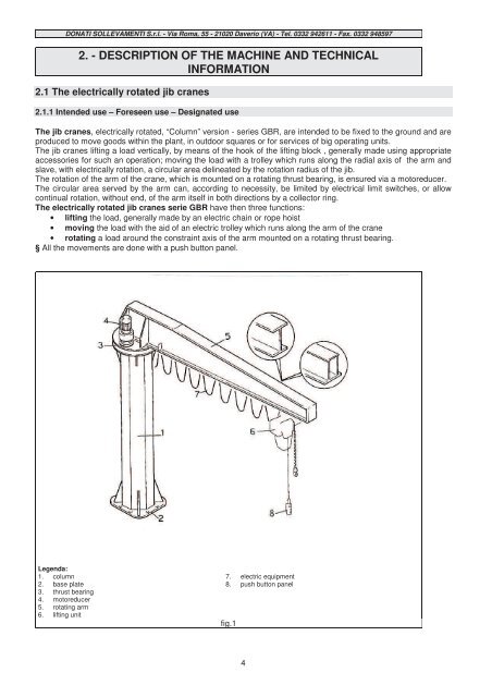
Legenda:<br />
1. column<br />
2. base plate<br />
3. thrust bearing<br />
4. motoreducer<br />
5. rotating arm<br />
6. lifting unit<br />
7. electric equipment<br />
8. push button panel<br />
fig.1<br />
4