

CHAPTER 3: PHYSICAL EFFECT OF VITIATION ON SCRAMJET ...
CHAPTER 3: PHYSICAL EFFECT OF VITIATION ON SCRAMJET ...
CHAPTER 3: PHYSICAL EFFECT OF VITIATION ON SCRAMJET ...

You also want an ePaper? Increase the reach of your titles
YUMPU automatically turns print PDFs into web optimized ePapers that Google loves.
<strong>CHAPTER</strong> 3: <strong>PHYSICAL</strong> <strong>EFFECT</strong> <strong>OF</strong> <strong>VITIATI<strong>ON</strong></strong> <strong>ON</strong> <strong>SCRAMJET</strong><br />
DESIGN<br />
1D-STUDY <strong>OF</strong> THE <strong>PHYSICAL</strong> <strong>EFFECT</strong> <strong>ON</strong> <strong>VITIATI<strong>ON</strong></strong> <strong>OF</strong> THE INCOMING AIR IN AN<br />
EXPERIMENTAL <strong>SCRAMJET</strong> COMBUSTOR<br />
Marc Bouchez, Rodolphe d’Incà<br />
Propulsion Department<br />
EADS - AEROSPATIALE – MATRA MISSILES<br />
8, rue Le Brix / 18020 BOURGES CEDEX / France<br />
marc.bouchez@missiles.aeromatra.com<br />
3.1 INTRODUCTI<strong>ON</strong><br />
Many ground test facilities use combustion to heat the air up to scramjet flight conditions. Even after<br />
replenishment of oxygen, the incoming air has then part of its nitrogen replaced with combustion products.<br />
When hydrogen burner is used in preheating air, the incoming flow contains typically 15% of water for Mach 6<br />
flight conditions and up to 30% for Mach 8 conditions.<br />
This vitiation has two effects:<br />
� A chemical effect (H2O, NOX, OH, even in low concentration are changing the ignition delay, particularly in<br />
the vicinity of 600 to 1000 K static temperature)<br />
� A physical effect : thermodynamics is changed by this composition change.<br />
The applied Physics Laboratory of John Hopkins University (APL) has proposed to RTO to give available<br />
experimental results of a scramjet combustor. Aerospatiale Matra Missiles (AMM) has proposed to do on this<br />
example a simple analysis of the physical effect of vitiation.<br />
This paper gives an example of the analysis of the flow in a scramjet combustor, where supersonic combustion<br />
leads to increase of pressure and slowing of the flow. This paper is mainly intended to contribute to the<br />
discussion of the effect of the water-vitiation of the incoming air by numerical simulations using simple tools<br />
(1D, 0D) and by performing several parametric studies.<br />
While the effect on all the parameters can be investigated, the focus here is on static pressure, Mach number, and<br />
heat fluxes, assuming the same (constant) wall temperature.<br />
The drag law and the combustion efficiency along the duct are generally taken constant whatever the<br />
composition of the incoming flow.<br />
3.2 EXPERIMENTAL COMBUSTOR<br />
3.2.1 COMBUSTOR SCHEMATIC<br />
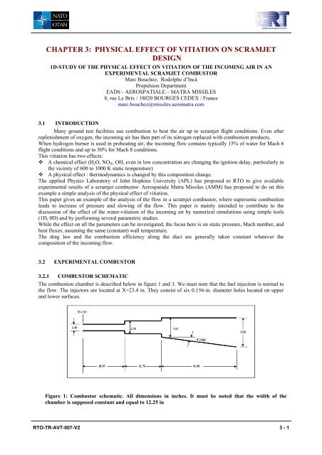
The combustion chamber is described below in figure 1 and 3. We must note that the fuel injection is normal to<br />
the flow. The injectors are located at X=23.4 in. They consist of six 0.156-in. diameter holes located on upper<br />
and lower surfaces.<br />
Figure 1: Combustor schematic. All dimensions in inches. It must be noted that the width of the<br />
chamber is supposed constant and equal to 12.25 in<br />
RTO-TR-AVT-007-V2 3 - 1
<strong>PHYSICAL</strong> <strong>EFFECT</strong> <strong>OF</strong> <strong>VITIATI<strong>ON</strong></strong> <strong>ON</strong> <strong>SCRAMJET</strong> DESIGN<br />
INPUT DATA<br />
The input data needed to achieve the simulations are presented in the following tables:<br />
FLOW DATA<br />
FUEL DATA<br />
Characteristics Value<br />
Supply pressure 400 psia<br />
Supply temperature 4200 °R<br />
Combustor entrance Mach N. 3.3<br />
Air mass flow rate 10.8 lbm/s<br />
Heater H2 flow rate 0.4 lbm/s<br />
Heater O2 flow rate 5.27 lbm/s<br />
Characteristics Value<br />
H2 injection Mach number 1<br />
H2 inject. Total pressure 217.4 psia<br />
H2 inject. Total temp 550 °R<br />
Experiments are carried out for the following equivalence ratios: ER=0.0, ER=0.51, ER=0.72 and ER=0.85.<br />
We assume a wall temperature of 550 °R along the whole duct.<br />
EXPERIMENTAL RESULTS<br />
The only data available after the test are the tap pressures along the combustor for the different equivalence<br />
ratios. An overview of all these data is presented in the graph below.<br />
Pressure (psia)<br />
70<br />
60<br />
50<br />
40<br />
30<br />
20<br />
10<br />
0<br />
Pressure Distribution Through Combustor<br />
0 10 20 30 40 50 60 70 80 90 100<br />
Axial Station (in.)<br />
ER=0.85<br />
ER=0.72<br />
ER=0.51<br />
ER=0.0<br />
Figure 2: APL wall pressure measurement on the experimental combustor wall for different ER<br />
It is interesting to note that the pressure sensors are not all located on the same face of the combustor. Given that<br />
the nature of the flow is quite different on each wall, we have to deal with these data very carefully.<br />
3 - 2 RTO-TR-AVT-007-V2
3.3 1D ANALYSIS <strong>OF</strong> THE FLOW<br />
3.3.1 1D ANALYSIS ASSUMPTI<strong>ON</strong>S<br />
The 1-D code PUMA ( a French acronym meaning One-dimensional Program for Analysis of<br />
Aerothermochemistry), has been used to provide a first analysis of the results. This code has been extensively<br />
used by AMM for advanced studies of scramjets and to provide a first analysis of experimental results such as<br />
CHAMOIS ione (see Ref.1).<br />
We must observe the limitations of this 1D study. Some effects that occur in the combustor, like shock<br />
waves or the recirculation zone behind the rear-facing step, are strongly 2D or 3D: we cannot directly integrate<br />
them into the program. That is why we must keep in mind that for, some cases (especially for high equivalence<br />
ratios), the results obtained are limited by the nature of the flow. Nevertheless, the 1D analysis is easy to be used<br />
in the frame of the present scope of this RTO report, and allows to perform parametric studies of the physical<br />
effect of the composition of the incoming air flow.<br />
The heat release law is tuned until a reasonable agreement is reached between 1-D results and experimental<br />
results. To this purpose, the balance between the heat release, the effective geometry and the drag has to be<br />
identified, in order to decide the contribution of each term to the measured wall pressure increase.<br />
In the present study, the choice is the following :<br />
8,00E-02<br />
6,00E-02<br />
4,00E-02<br />
2,00E-02<br />
0,00E+00<br />
<strong>PHYSICAL</strong> <strong>EFFECT</strong> <strong>OF</strong> <strong>VITIATI<strong>ON</strong></strong> <strong>ON</strong> <strong>SCRAMJET</strong> DESIGN<br />
Duct Area<br />
0,00 0,50 1,00 1,50 2,00 2,50<br />
Figure 3: assumed duct area variation (geometry) of APL combustor (m²)<br />
� To use the “geometrical geometry” as the flow boundary (no decrease due to boundary layer or<br />
subsonic zone), see Figure 3.<br />
� To tune the drag with the non reactive case, and keep the same tuning constant for the reactive<br />
cases; the local skin friction coefficient is computed using semi-empirical laws and the 1D<br />
parameters of the flow, and sometimes increased by a factor in order to account for other types<br />
of drag. The multiplication factor is kept the same for any ER from 0 to 1.<br />
� To derive from the pressure on the wall the heat release law, using simple combustion<br />
modeling and a single reaction. The combustion efficiency dependence along the duct is then<br />
kept the same during the vitiation parametric study.<br />
The PUMA code is also able to estimate the heat fluxes along the combustor. The heat transfer coefficient is<br />
estimated using semi-empirical equations (Colburn law) in a duct. To take into account compressibility effects<br />
and non-adiabatic wall conditions, the Spalding and Chi equation has been used (see Ref.2).<br />
Reference 2 reports a comparison of the method used here for another, more complex scramjet combustor,<br />
CHAMOIS. These fluxes had been computed for two different wall temperatures, 700 K and 1100 K,<br />
corresponding to the range of temperatures measured along the duct at its operating conditions. They have been<br />
compared with the post-processed results of the heat-flux-meters. Because CHAMOIS is a heat-sink facility, the<br />
wall temperature varies with time and spatially along the duct. Inverse methods are used to take into account the<br />
delay due to heat propagation between the two thermocouples of the heat flux meter. Figure 4 gives this<br />
comparison for the operating conditions investigated.<br />
RTO-TR-AVT-007-V2 3 - 3
<strong>PHYSICAL</strong> <strong>EFFECT</strong> <strong>OF</strong> <strong>VITIATI<strong>ON</strong></strong> <strong>ON</strong> <strong>SCRAMJET</strong> DESIGN<br />
3500000<br />
3000000<br />
2500000<br />
2000000<br />
1500000<br />
1000000<br />
500000<br />
0<br />
( )<br />
Surfacic flux (W/m 2 ): kerosene 0,5 + H2 0,2<br />
( )<br />
0 0,5 1 1,5 2 2,5 3<br />
abscisse (m)<br />
Right wall<br />
Upper wall<br />
Lower wall<br />
PUMA for Tw 700K<br />
PUMA for Tw 1100 K<br />
Figure 4: Heat flux (W/m²) along the CHAMOIS scramjet (experimental or PUMA data on another<br />
scramjet show sufficient accuracy for the formula used in the present study) .<br />
For the first part of the present study, chemical kinetics is modeled as one irreversible reaction:<br />
H2 + ½ O2 → H2O<br />
3.3.2 N<strong>ON</strong> REACTIVE COMPUTATI<strong>ON</strong>S<br />
These are the results obtained with ER=0. There are 2 cases: one where the drag coefficient is simply<br />
computed with Spalding’s formula, the other with “corrected” drag coefficient. The purpose of this computation<br />
is, first, to see the difference between then computed results and the experimental results and, secondly, to see<br />
the effect of the drag coefficient on the shape of the pressure curves. Indeed, the experimental device is made of<br />
two steps and of a diverging part; the two steps can be responsible for strong 2D effects (like expansion and<br />
shock waves, recirculation zones) that cannot be easily computed with a 1D code like PUMA.<br />
Two cases have been illustrated, with or without the correction (multiplication factor)<br />
Case 1: ER=0. – Spalding’s law of drag – vitiated airflow<br />
Case 2: ER=0. – corrected Spalding’s law of drag: the drag coefficient is increased by 20 for the first step and by<br />
10 for the second one. This correction is supposed to simulate the effects of throttling or overexpansion on the<br />
wall pressure.<br />
1,00E+05<br />
8,00E+04<br />
6,00E+04<br />
4,00E+04<br />
2,00E+04<br />
0,00E+00<br />
Static Pressures<br />
0,00 0,50 1,00 1,50 2,00 2,50<br />
Figure 5: Non reactive computations : pressure (Pa)<br />
Cas 1<br />
cas 2<br />
Exp.<br />
3 - 4 RTO-TR-AVT-007-V2
For the case 1, the PUMA code computes only a quick expansion for the steps that is obviously not in<br />
agreement with experimental data.<br />
The results are better with the case 2: the artificial increase of the drag coefficient improves the value of<br />
the pressure for the first step. However, there is a pike after the second step that cannot be simulated.<br />
The corresponding Mach number is shown below :<br />
flow.<br />
4,00<br />
3,00<br />
2,00<br />
1,00<br />
0,00<br />
Mach<br />
0,00 0,50 1,00 1,50 2,00 2,50<br />
Figure 6: Non reactive computations (Mach number)<br />
Cas 1<br />
Cas 2<br />
The static temperature has to be examined, in particular to see the ignition capability with the present<br />
1500,00<br />
1000,00<br />
500,00<br />
0,00<br />
<strong>PHYSICAL</strong> <strong>EFFECT</strong> <strong>OF</strong> <strong>VITIATI<strong>ON</strong></strong> <strong>ON</strong> <strong>SCRAMJET</strong> DESIGN<br />
Static Temperatures<br />
0,00 0,50 1,00 1,50 2,00 2,50<br />
Figure 7 : 1D static temperature (K) before combustion<br />
Cas 1<br />
Cas 2<br />
Self ignition of the hydrogen is expected at this air temperature. The chemical effect of water in the<br />
incoming flow is outside the scope of the present RTO subgroup task. Nevertheless, it is know that its effect on<br />
ignition delay is maximum in the vicinity of 1000/T=1: exactly the value at the present test conditions.<br />
RTO-TR-AVT-007-V2 3 - 5
<strong>PHYSICAL</strong> <strong>EFFECT</strong> <strong>OF</strong> <strong>VITIATI<strong>ON</strong></strong> <strong>ON</strong> <strong>SCRAMJET</strong> DESIGN<br />
3.3.3 REACTIVE CASE (ER=0.51)<br />
Now, we study the case of hydrogen injection with ER=0.51. The goal is to compute a combustion<br />
efficiency which yields the same pressure results as in the experiment.<br />
Several cases have been computed, depending on the way to compute the drag, the composition of the incoming<br />
air (31%, 22% (reference) or 0% of water mass fraction in the incoming air).<br />
Case 3b: ER=0.51 – vitiated airflow – Spalding’s drag coefficient. We do not tune automatically the combustion<br />
efficiency ETAC(x) but assume a linear law. This approach predicts a computed maximum pressure which is too<br />
low in comparison with the experimental pressure (there are more shocks).<br />
Case 4: ER=0.51 – vitiated airflow – Corrected Spalding’s drag coefficient. Here the results are far better, since<br />
we have a good agreement between computed and experimental data.<br />
Case 4b: ER=0.51 –vitiated airflow (composition YH2O=0.31). Corrected Spalding’s drag coefficient.<br />
4,00<br />
3,00<br />
2,00<br />
1,00<br />
0,00<br />
Mach<br />
0,00 0,50 1,00 1,50 2,00 2,50<br />
2,00E+05<br />
1,50E+05<br />
1,00E+05<br />
5,00E+04<br />
0,00E+00<br />
Figure 8 : Computed Mach number for several assumptions (ER=0.51)<br />
Pressures<br />
0,00 0,50 1,00 1,50 2,00 2,50<br />
Figure 9: Pressure (Pa) for different assumptions (ER=0.51)<br />
Cas3b<br />
Cas4b<br />
cas4<br />
Cas3b<br />
Cas4b<br />
cas4<br />
Exp<br />
We clearly see here the differences between each case. The case 3b has a good x profile but its<br />
maximum pressure is too low: the Spalding’s law alone cannot simulate the big shock effects occurring at the<br />
injection point (the flow strongly interacts with the fuel jet generating a shock wave). To integrate this<br />
3 - 6 RTO-TR-AVT-007-V2
phenomenon in the simulation we locally multiply the drag coefficient by 20 (and by 10 for the steps). This is<br />
case 4, which is the reference for the following computations in order to study the physical effect of vitiation.<br />
The corresponding laws of combustion efficiency assumed along the duct are the following:<br />
1,50<br />
1,00<br />
0,50<br />
0,00<br />
ETAC<br />
0,00 0,50 1,00 1,50 2,00 2,50<br />
Figure 10: Combustion efficiency law along the duct (ER=0.51)<br />
Cas3b<br />
Cas4b<br />
cas4<br />
The heat transfer parameters at the wall can also be computed for the different cases, with the uniform<br />
wall temperature assumed constant at 305 K.<br />
600,00<br />
400,00<br />
200,00<br />
0,00<br />
Hwall<br />
0,00 0,50 1,00 1,50 2,00 2,50<br />
Figure 11: Heat fluxes along the duct at ER=0.51<br />
<strong>PHYSICAL</strong> <strong>EFFECT</strong> <strong>OF</strong> <strong>VITIATI<strong>ON</strong></strong> <strong>ON</strong> <strong>SCRAMJET</strong> DESIGN<br />
Cas3b<br />
Cas4b<br />
cas4<br />
This study illustrates also the uncertainty of the 1D analysis for such a 2D supersonic reactive flow.<br />
At this point, parametric studies of the effect of the composition of the incoming air can be performed, assuming<br />
the same combustion efficiency evolution along the duct, ETAC(x).<br />
3.4 <strong>EFFECT</strong> <strong>OF</strong> <strong>VITIATI<strong>ON</strong></strong><br />
A first 1D assumes the same combustion and drag laws, and has been performed with pure or watervitiated<br />
air:<br />
Case 4: ER=0.51 – Corrected Spalding’s law of drag – vitiated airflow (22% of water)<br />
Case 6: ER=0.51 – Corrected Spalding’s law of drag – pure airflow – same ETAC(x) as for the case 4<br />
Same Mach number, static temperature (for the same ignition environment), same static pressure (and<br />
same geometry)have been assumed at the entrance.<br />
RTO-TR-AVT-007-V2 3 - 7
<strong>PHYSICAL</strong> <strong>EFFECT</strong> <strong>OF</strong> <strong>VITIATI<strong>ON</strong></strong> <strong>ON</strong> <strong>SCRAMJET</strong> DESIGN<br />
3,50<br />
3,00<br />
2,50<br />
2,00<br />
1,50<br />
pure<br />
vitiated<br />
Mach<br />
Mach-cas4<br />
Mach-cas6<br />
1,00<br />
0,00 0,50 1,00 1,50 2,00 2,50<br />
Figure 12: Computed effect of vitiation on Mach number<br />
The computed effect is different after each step, probably because the 1D analysis is not appropriate in<br />
such a sudden expansion of the flow.<br />
2,00E+05<br />
1,80E+05<br />
1,60E+05<br />
1,40E+05<br />
1,20E+05<br />
1,00E+05<br />
8,00E+04<br />
6,00E+04<br />
4,00E+04<br />
2,00E+04<br />
0,00E+00<br />
Static Pressures (Pa)<br />
pure<br />
vitiated<br />
+ 9%<br />
Static_Pressures-cas4<br />
Static_Pressures-cas6<br />
vitiated<br />
0,00 0,50 1,00 1,50 2,00 2,50<br />
Figure 13: Computed effect of vitiation on pressure (Pa)<br />
The opposite effect on Mach number and static pressure is visible in figures 12-13. The effect of<br />
vitiation on the computed heat flux (see figure 14) is note worthy: vitiation of the flow, within the assumptions<br />
made, leads to an increase of heat flux (about 5%). In this case, the check-out of a thermal protection or a<br />
cooling circuit should lead to a conservative design.<br />
3 - 8 RTO-TR-AVT-007-V2<br />
pure
5000000<br />
4500000<br />
4000000<br />
3500000<br />
3000000<br />
2500000<br />
2000000<br />
1500000<br />
Wall heat flux densities (W/m²)<br />
vitiated +4%<br />
pure<br />
DFCV-cas4<br />
DFCV-cas6<br />
1000000<br />
0,00 0,50 1,00 1,50 2,00 2,50<br />
Figure 14: Computed effect of vitiation on heat fluxes<br />
3.4.1 <strong>EFFECT</strong> <strong>OF</strong> COMBUSTI<strong>ON</strong> DISSOCIATI<strong>ON</strong>S (EQUILIBRIUM MODELING <strong>OF</strong><br />
COMBUSTI<strong>ON</strong>)<br />
These first results have been extended, in particular to take into account the possible effect of incoming<br />
water on the combustion heat release (in the previous computations, only one reaction was considered).<br />
Combustion has been simulated using the same code but with equilibrium assumptions and more species (H2,<br />
O2, N2, H2O, NO, OH, H, O and N are considered). The Mach number, temperature, pressure and heat fluxes<br />
are very slightly modified.<br />
Two new cases have been computed, with the same assumptions as cases 4 and 6, except the<br />
combustion modeling:<br />
Case 8 : ER=0.51 – Corrected Spalding’s law of drag – vitiated airflow– same ETAC(x) as for the case 4<br />
Case 7 : ER=0.51 – Corrected Spalding’s law of drag – pure airflow – same ETAC(x) as for the case 4<br />
Equilibrium reduces the computed temperature, as shown for example on the static temperature profile of figure<br />
15:<br />
2400<br />
2200<br />
2000<br />
1800<br />
1600<br />
1400<br />
1200<br />
<strong>PHYSICAL</strong> <strong>EFFECT</strong> <strong>OF</strong> <strong>VITIATI<strong>ON</strong></strong> <strong>ON</strong> <strong>SCRAMJET</strong> DESIGN<br />
Static Temperature (K)<br />
cas 6 - pure air - one reaction<br />
cas 7 - pure air - equilibrium<br />
cas 4 - vitiated air - one reaction<br />
cas 8 - vitiated air - equilibrium<br />
Static_Temperatures-cas4<br />
Static_Temperatures-cas6<br />
Static_Temperatures-cas7<br />
Static_Temperatures-cas8<br />
1000<br />
0,00 0,50 1,00 1,50 2,00 2,50<br />
Figure 15: Effect of air vitiation and combustion modeling on static temperature<br />
RTO-TR-AVT-007-V2 3 - 9
<strong>PHYSICAL</strong> <strong>EFFECT</strong> <strong>OF</strong> <strong>VITIATI<strong>ON</strong></strong> <strong>ON</strong> <strong>SCRAMJET</strong> DESIGN<br />
Some species computed are reported in figures 16-17, beginning with water:<br />
35%<br />
30%<br />
25%<br />
20%<br />
15%<br />
10%<br />
5%<br />
mass fraction of H2O<br />
H2O-cas4<br />
H2O-cas6<br />
H2O-cas7<br />
H2O-cas8<br />
0%<br />
0,00 0,50 1,00 1,50 2,00 2,50<br />
Figure 16: Water mass fraction computed along the duct<br />
The equilibrium computations logically lead to 1% of NO in the hot gases, in the zone of the maximum<br />
static temperature (see figure 17):<br />
0,012<br />
0,01<br />
0,008<br />
0,006<br />
0,004<br />
0,002<br />
mass fraction of NO<br />
vitiated<br />
NO-cas4<br />
NO-cas6<br />
NO-cas7<br />
NO-cas8<br />
0<br />
0,00 0,50 1,00 1,50 2,00 2,50<br />
pure<br />
Figure 17: Computed NO along the duct<br />
The angles of the shock and the expansion fans could be slightly different in pure and vitiated flow, as it<br />
can be derived from the specific heat ratio shown on Figure 18 ; 2D or 3D computations could provide<br />
interesting data but they are outside the scope of the present RTO subgroup task.<br />
3 - 10 RTO-TR-AVT-007-V2
1,36<br />
1,34<br />
1,32<br />
1,30<br />
1,28<br />
1,26<br />
1,24<br />
1,22<br />
water-vitiated<br />
<strong>PHYSICAL</strong> <strong>EFFECT</strong> <strong>OF</strong> <strong>VITIATI<strong>ON</strong></strong> <strong>ON</strong> <strong>SCRAMJET</strong> DESIGN<br />
"pure"<br />
Gamma_gases<br />
Gamma_gases-cas4<br />
Gamma_gases-cas6<br />
Gamma_gases-cas7<br />
Gamma_gases-cas8<br />
0,00 0,50 1,00 1,50 2,00 2,50<br />
Figure 18: Specific heat ratio of the gases along the duct<br />
Nevertheless, the effect of gamma on oblique shock at Mach 2.5 is very small (Mach after a 6° wedge<br />
varies from 2.27 to 2.28 and the deviation from 28.1 to 28.0°, static parameters change is less than 1%).<br />
3.5 C<strong>ON</strong>CLUSI<strong>ON</strong>S AND RECOMMENDATI<strong>ON</strong>S<br />
A first analysis of the APL scramjet combustor has been carried on at AMM using 1-D codes.<br />
Comparison of a scramjet operation with water or not in the incoming air has been performed. The present<br />
analysis is focused on the physical effect of the water-vitiation only: the combustion efficiency is assumed to be<br />
the same.<br />
Vitiation, with these assumptions, leads to increase the heat fluxes (by 5%) and (generally) of the static pressure,<br />
in comparison with pure air.<br />
Although the modeling in the simulations is somewhat crude, their results are suggestive of effects potentially<br />
important.<br />
Therefore it is strongly recommended that this analysis could be profitably enhanced by 3D computations and by<br />
testing of the same combustor in two different test facilities (with or without water in the incoming flow).<br />
3.6 REFERENCES<br />
1 E. Dufour, M. Bouchez, “Post-Experimental computations of a kerosene-fuelled scramjet”, AIAA-2001-1817,<br />
Kyoto, Japan, April 2001<br />
2 Handbook of Heat Transfer fundamentals, Mc Graw Hill editors, P.8.151 – table 14.<br />
RTO-TR-AVT-007-V2 3 - 11
<strong>PHYSICAL</strong> <strong>EFFECT</strong> <strong>OF</strong> <strong>VITIATI<strong>ON</strong></strong> <strong>ON</strong> <strong>SCRAMJET</strong> DESIGN<br />
3 - 12 RTO-TR-AVT-007-V2


