

Electromechanical products Compabloc 1000
Electromechanical products Compabloc 1000
Electromechanical products Compabloc 1000

Create successful ePaper yourself
Turn your PDF publications into a flip-book with our unique Google optimized e-Paper software.
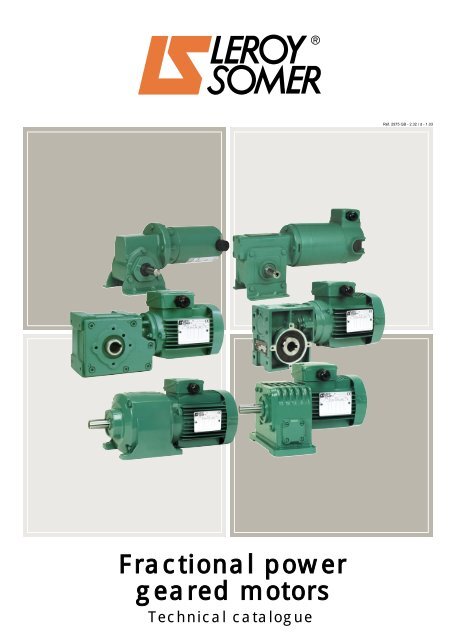
Fractional power<br />
geared motors<br />
Technical catalogue<br />
Réf. 2975 GB - 2.32 / d - 1.03
This catalogue presents, in three sections, the LEROY-SOMER range of<br />
fractional power gearboxes and geared motors.<br />
• 1st section<br />
Each type of gearbox is presented in a format allowing the reader to see the<br />
following clearly :<br />
• Product presentation : characteristics and construction<br />
• Adaptation possibilities and designation<br />
• Mounting positions<br />
• Quick selection data (duty factor K P ≥ 1)<br />
• Table of technical characteristics for a precise definition of slow speed shaft<br />
torques at the exact output speed, duty factor, and the most common motor<br />
types<br />
• The force on the slow speed shafts (axial and radial)<br />
• Dimensions (feet, baseplate, flange etc.)<br />
• 2nd section<br />
• The motors most commonly used :<br />
– 3-phase and single phase induction with or without brake<br />
– D.C. with and without brake,<br />
with their main characteristics.<br />
• 3rd section<br />
• Variable speed drives :<br />
– based on induction motors<br />
– based on D.C. motors<br />
with their main characteristics.<br />
For additional features and higher power ratings, please contact your Leroy-<br />
Somer representative.
Leroy-Somer's extensive experience in<br />
all areas of industrial power and motor<br />
transmission has enabled the company<br />
to develop a complete range of geared<br />
motors for "fractional" power ratings.<br />
These <strong>products</strong> will satisfy the user's<br />
requirements (in terms of reliability and<br />
performance) in the same way as the<br />
"industrial" <strong>products</strong>, whilst responding<br />
to the specific needs of the "fractional"<br />
market.<br />
Certain plants in the Leroy-Somer<br />
group have thus become specialists in<br />
the design and manufacture of these<br />
<strong>products</strong> (motors and gearboxes).<br />
All gearboxes presented in this catalogue<br />
contain components selected for their<br />
quality and performance.<br />
For example :<br />
• The shafts (output or countershaft)<br />
are mounted exclusively on ball<br />
bearings.<br />
• Computer modelling is used for<br />
calculation and optimisation of the<br />
indentations, and the gear mechanisms<br />
on all models are manufactured from<br />
the most suitable materials.<br />
Introduction to<br />
electromechanical <strong>products</strong><br />
• Reduction gears : all gear mechanisms<br />
are made from machine-finished<br />
hardened steel. The input trains benefit<br />
from micro-finishing ensuring a<br />
particularly low noise level.<br />
• Worm gears : all gears are bronze<br />
(never synthetic) and the alloy is<br />
optimised for the intended function ;<br />
shaped screws in hardened steel<br />
subjected to either heat treatment and<br />
precision grinding, or ionitride surface<br />
treatment (depending on type).<br />
Moreover, all gear housing, produced<br />
by computer-aided design (CAD),<br />
complies with market requirements :<br />
size and weight are reduced to a<br />
minimum, and they are easy for the<br />
user to service and install.<br />
Finally, and to ensure the <strong>products</strong> are<br />
easy to use, all gearboxes are<br />
lubricated for life and delivered "ready<br />
for use".<br />
The motors which accompany the<br />
gearboxes in this catalogue are the<br />
most commonly used models. As with<br />
the gearboxes, these motors are<br />
based on the industrial range and<br />
comply with the most stringent<br />
operating standards.<br />
The <strong>products</strong> in this catalogue<br />
represent the base for "fractional"<br />
equipment.<br />
Any specific application involving<br />
requirements for special<br />
characteristics, both mechanical and<br />
electrical, can be discussed with<br />
Leroy-Somer technical departments.<br />
3
4<br />
GENERAL INFORMATION .......................................<br />
<strong>Electromechanical</strong> <strong>products</strong><br />
Contents<br />
PAGES<br />
Quality assurance 7<br />
Units of measurement and standard formulae 8<br />
- Electricity and Electromagnetism ................................<br />
- Thermal ..................................................................................<br />
- Noise and vibration ............................................................<br />
- Dimensions ...........................................................................<br />
- Mechanics .............................................................................<br />
Unit conversions 11<br />
Standard formulae used in electrical engineering 12<br />
- Mechanical formulae .........................................................<br />
- Electrical formulae .............................................................<br />
Selecting a geared motor 14<br />
Motor shafts and flanges for gearboxes 15<br />
Flow chart 17<br />
7<br />
8<br />
9<br />
9<br />
9<br />
10<br />
12<br />
13<br />
PAGES<br />
- AXIAL OUTPUT GEARED<br />
MOTORS................................................................... A1.1<br />
<strong>Compabloc</strong> <strong>1000</strong> (Helical gear mechanism) A1.1<br />
A1.1<br />
A1.2<br />
A1.3<br />
A1.4<br />
A1.6<br />
A1.10<br />
A1.15<br />
A1.20<br />
Minibloc MVAB (Double worm type) A2.1<br />
- General - construction .................................................<br />
- Mounting positions ........................................................<br />
- Adaptation possibilities ...............................................<br />
- Quick selection ...............................................................<br />
- Technical selection .......................................................<br />
- Gearbox only (AP) characteristics .........................<br />
- Load on slow speed shaft ..........................................<br />
- Dimensions ......................................................................<br />
LEROY-SOMER reserves the right to modify the design, technical specifications and dimensions of the <strong>products</strong> shown in this catalogue.<br />
The descriptions cannot in any way be considered contractual.<br />
A<br />
- General - construction .................................................<br />
- Mounting positions ........................................................<br />
- Adaptation possibilities ...............................................<br />
- Quick selection ...............................................................<br />
- Technical selection .......................................................<br />
- Gearbox only (AP) characteristics .........................<br />
- Load on slow speed shaft ..........................................<br />
- Dimensions ......................................................................<br />
A2.1<br />
A2.2<br />
A2.3<br />
A2.4<br />
A2.5<br />
A2.6<br />
A2.7<br />
A2.8
B<br />
<strong>Electromechanical</strong> <strong>products</strong><br />
Contents<br />
PAGES<br />
- PERPENDICULAR OUTPUT<br />
GEARED MOTORS ......................................... B1.1<br />
Minibloc MVB (Worm) B1.1<br />
- General - construction .................................................<br />
- Mounting positions ........................................................<br />
- Adaptation possibilities ...............................................<br />
- Selection guide ...............................................................<br />
- Selection data .................................................................<br />
- Load on slow speed shaft ..........................................<br />
- Dimensions ......................................................................<br />
Minibloc MVA (Worm) B2.1<br />
- General - construction .................................................<br />
- Mounting positions ........................................................<br />
- Adaptation possibilities ...............................................<br />
- Selection guide ...............................................................<br />
- Selection data .................................................................<br />
- Gearbox only (AP) characteristics .........................<br />
- Load on slow speed shaft ..........................................<br />
- Dimensions ......................................................................<br />
B2.1<br />
B2.2<br />
B2.3<br />
B2.4<br />
B2.6<br />
B2.8<br />
B2.9<br />
B2.11<br />
Multibloc 2100 (Worm) B3.1<br />
- General - construction .................................................<br />
- Mounting positions ........................................................<br />
- Adaptation possibilities ...............................................<br />
- Selection guide ...............................................................<br />
- Selection data .................................................................<br />
- Gearbox only (AP) characteristics .........................<br />
- Load on slow speed shaft ..........................................<br />
- Dimensions ......................................................................<br />
B3.1<br />
B3.2<br />
B3.3<br />
B3.4<br />
B3.6<br />
B3.8<br />
B3.9<br />
B3.10<br />
Minibloc MVDE - MVBE (Worm and gear<br />
combination) B4.1<br />
- General - construction .................................................<br />
- Mounting positions ........................................................<br />
- Adaptation possibilities ...............................................<br />
- Selection guide ...............................................................<br />
- Selection data .................................................................<br />
- Load on slow speed shaft ..........................................<br />
- Dimensions ......................................................................<br />
B1.1<br />
B1.2<br />
B1.3<br />
B1.4<br />
B1.6<br />
B1.8<br />
B1.9<br />
B4.1<br />
B4.2<br />
B4.3<br />
B4.4<br />
B4.5<br />
B4.7<br />
B4.9<br />
C<br />
PAGES<br />
- FIXED-SPEED GEARED MOTORS C1.1<br />
LS 3-phase induction motors C1.1<br />
- General - construction .................................................<br />
- Selection - characteristics ..........................................<br />
C1.1<br />
C1.2<br />
LS single phase induction motors C2.1<br />
- General - construction .................................................<br />
- Selection - characteristics ..........................................<br />
C2.1<br />
C2.2<br />
FMC brake induction motors C3.1<br />
- General .............................................................................<br />
- Selection - characteristics ..........................................<br />
C3.1<br />
C3.2<br />
FCR brake induction motors C4.1<br />
- General .............................................................................<br />
- Selection - characteristics ..........................................<br />
C4.1<br />
C4.2<br />
FAST brake induction motors C5.1<br />
- General .............................................................................<br />
- Selection - characteristics ..........................................<br />
C5.1<br />
C5.2<br />
MFA enclosed D.C. motors C6.1<br />
- General - construction .................................................<br />
- Mounting positions ........................................................<br />
- Selection - characteristics ..........................................<br />
- Dimensions ......................................................................<br />
C6.1<br />
C6.2<br />
C6.3<br />
C6.4<br />
MBT low voltage D.C. motors C7.1<br />
- General - construction .................................................<br />
- Mounting positions ........................................................<br />
- Selection - characteristics ..........................................<br />
- Dimensions ......................................................................<br />
C7.1<br />
C7.2<br />
C7.3<br />
C7.4<br />
5
D<br />
6<br />
<strong>Electromechanical</strong> <strong>products</strong><br />
Contents<br />
PAGES<br />
- VARIABLE SPEED DRIVE<br />
GEARED MOTORS ........................................ D1.1<br />
MINIDRIVE electronic variable speed drives D1.1<br />
- General .............................................................................<br />
- Mounting positions .......................................................<br />
- Adaptation possibilities ..............................................<br />
- Pilot control and functions ........................................<br />
- Selection ..........................................................................<br />
- Dimensions .....................................................................<br />
VARMECA variable speed motors<br />
+ geared motors<br />
- General - construction ..............................................<br />
- Mounting positions .......................................................<br />
- Adaptation possibilities ..............................................<br />
- Options .............................................................................<br />
- Selection ..........................................................................<br />
- VARMECA dimensions...............................................<br />
- VARMECA + <strong>Compabloc</strong> <strong>1000</strong> selection............<br />
- VARMECA + <strong>Compabloc</strong> <strong>1000</strong> dimensions.......<br />
- VARMECA + Multibloc 2100 selection................<br />
- VARMECA + Multibloc 2100 dimensions...........<br />
D1.1<br />
D1.2<br />
D1.3<br />
D1.4<br />
D1.6<br />
D1.8<br />
D2.1<br />
D2.1<br />
D2.2<br />
D2.3<br />
D2.4<br />
D2.5<br />
D2.6<br />
D2.10<br />
D2.12<br />
D2.18<br />
D2.19<br />
PAGES<br />
MVE electronic variable speed drives D3.1<br />
- General - construction ..............................................<br />
- Mounting positions .......................................................<br />
- Adaptation possibilities ..............................................<br />
- Selection - characteristics .........................................<br />
- MVE dimensions............................................................<br />
- MVE + <strong>Compabloc</strong> <strong>1000</strong> selection.........................<br />
- MVE + <strong>Compabloc</strong> <strong>1000</strong> dimensions....................<br />
- MVE + Minibloc MVA selection...............................<br />
- MVE + Minibloc MVA dimensions..........................<br />
- MVE + Multibloc 2100 selection..............................<br />
- MVE + Multibloc 2100 dimensions.........................<br />
- MVE + Minibloc MVDE - MVBE selection...........<br />
- MVE + Minibloc MVDE - MVBE dimensions......<br />
D3.1<br />
D3.2<br />
D3.3<br />
D3.4<br />
D3.5<br />
D3.8<br />
D3.9<br />
D3.12<br />
D3.13<br />
D3.14<br />
D3.15<br />
D3.17<br />
D3.18
Industrial concerns are having to cope<br />
with an ever more competitive<br />
environment. Productivity depends to a<br />
considerable degree on the right<br />
investment at the right time.<br />
LEROY-SOMER has the answer,<br />
building motors to precise standards of<br />
quality.<br />
When carrying out quality checks on a<br />
machine's performance, the first step is<br />
to measure the level of customer<br />
satisfaction.<br />
Careful study of this information tells<br />
us which points need looking at,<br />
improving and monitoring.<br />
From the moment you place your order<br />
with our administrative staff until the<br />
motor is up and running (after design<br />
studies, launch and production<br />
activities) we keep you informed and<br />
involved.<br />
Our own procedures are constantly<br />
under review. All our staff are involved<br />
in both operational process analysis<br />
and continuous training programmes.<br />
These initiatives help them serve you<br />
better, and increased skills bring<br />
increased motivation.<br />
General information<br />
Quality assurance<br />
At LEROY-SOMER, we think it vital for<br />
our customers to know the importance<br />
we attach to quality.<br />
LEROY-SOMER has entrusted the<br />
certification of its expertise to various<br />
international organizations.<br />
Certification is granted by independent<br />
professional auditors, and recognises<br />
the high standards of the<br />
company's quality assurance procedures.<br />
All activities resulting in the final version<br />
of the machine have therefore<br />
received official ISO 9000 accreditation.<br />
Products are also<br />
approved by official bodies<br />
who inspect their<br />
technical performance<br />
with regard to the various<br />
standards.<br />
This is a fundamental<br />
requirement for a company<br />
of international<br />
standing.<br />
7
8<br />
General information<br />
Units of measurement and standard formulae<br />
ELECTRICITY AND ELECTROMAGNETISM<br />
Quantity Units<br />
Name French name Symbol Definition SI<br />
Frequency Fréquence<br />
Période<br />
f 1<br />
f =<br />
T<br />
Hz (hertz)<br />
Electric current Courant électrique<br />
(intensité de)<br />
I A (amps)<br />
Electrical potential Potentiel électrique V V (volt)<br />
Voltage Tension U<br />
Electromotive force Force électromotrice E<br />
Non SI,<br />
but accepted<br />
Phase angle Déphasage ϕ U = Um cosωt rad ° degree<br />
i = im cos (ωt -ϕ)<br />
Power factor Facteur de puissance cos ϕ<br />
Reactance Réactance X Z = IZI jϕ<br />
Resistance Résistance R = R + jX Ω (ohm)<br />
IZI = √ R 2 + X 2<br />
Impedance Impédance Z<br />
X = Lω −<br />
1<br />
Cω<br />
Self inductance Inductance propre (self) L<br />
Φ H (henry)<br />
L =<br />
I<br />
Capacitance Capacité C Q<br />
C =<br />
V<br />
F (farad)<br />
Charge électrique, Q Q = ∫Ιdt C (coulomb) A.h<br />
Quantity of electricity Quantité d'électricité<br />
1 A.h = 3600 C<br />
Resistivity Résistivité ρ<br />
R.S<br />
ρ =<br />
I<br />
Ω .m Ω /m<br />
Conductance Conductance G<br />
Number of turns (coil) Nombre de tours (spires)<br />
de l'enroulement<br />
N<br />
Number of phases Nombre de phases m<br />
Number of pairs of poles Nombre de paires de pôles p<br />
Units and expressions<br />
not recommended<br />
Conversion<br />
1 S (siemens) 1/ Ω = 1S<br />
G =<br />
R<br />
Magnetic field Champ magnétique H A/m<br />
Magnetic potential difference Différence de potentiel Um A<br />
magnétique<br />
Magnetomotive force Force magnétomotrice F, Fm F = φHs ds<br />
Solénation, courant totalisé H H = NI<br />
Magnetic induction<br />
Induction magnétique, B T (Tesla) = Wb/m<br />
Magnetic flux density Densité de flux magnétique<br />
2 (gauss) 1 G = 10-4 T<br />
Magnetic flux Flux magnétique,<br />
Φ Φ = ƒƒs Bn ds Wb (weber) (maxwell)<br />
Flux d'induction magnétique<br />
1 max = 10-8 The unit AT (ampere-turns)<br />
is incorrect because it treats<br />
"turn" as a physical unit<br />
Wb<br />
Magnetic vector potential Potentiel vecteur magnétique A Wb/m<br />
Permeability Perméabilité d'un milieu µ = µo µr B = µH H/m<br />
Permeability of vacuum Perméabilité du vide µo µo = 4π10 -7 H/m<br />
Permittivity Permittivité ε = εoεr 1<br />
36 π 10<br />
F/m<br />
9<br />
εo = F/m<br />
j is defined as j 2 = -1<br />
ω pulsation = 2 π . f
THERMODYNAMICS<br />
General information<br />
Quantity Units<br />
Name French name Symbol Definition SI<br />
Non SI,<br />
but accepted<br />
Temperature Température T, K (kelvin) temperature<br />
Thermodynamic Thermodynamique Celsius, θ, °C<br />
T = θ + 273.15<br />
Units and expressions<br />
not recommended<br />
Conversion<br />
Temperature rise Ecart de température ∆T K °C 1 °C = 1 K<br />
Heat flux density Densité de flux thermique q, ϕ Φ<br />
q =<br />
A<br />
Thermal conductivity Conductivité thermique λ W/m.K<br />
Total heat transmission Coefficient de transmission K ϕ = K (Tr2 - Tr1) W/m 2 .K<br />
coefficient thermique global<br />
Heat capacity Capacité thermique C dQ J/K<br />
C =<br />
dT<br />
Specific heat capacity Capacité thermique c C<br />
c =<br />
massique m J/kg.K<br />
Internal energy Energie interne U J<br />
NOISE AND VIBRATION<br />
Quantity Units<br />
Name French name Symbol Definition SI<br />
Non SI,<br />
but accepted<br />
Units and expressions<br />
not recommended<br />
conversions<br />
Sound power level Niveau de puissance Lw L W =10 lg (P/P o ) dB lg logarithm to base 10<br />
acoustique (P o = 10 -12 W) (decibel) lg10 = 1<br />
Sound pressure level Niveau de pression Lp L p =20 lg (P/P o ) dB<br />
DIMENSIONS<br />
acoustique (P o =2 x10 -5 Pa)<br />
Quantity Units<br />
Name French name Symbol Definition SI<br />
Non SI,<br />
but accepted<br />
Units and expressions<br />
not recommended<br />
conversions<br />
Angle (plane angle) Angle (angle plan) α, β, T, ϕ degree :° 180° : π rad<br />
minute : '<br />
second : "<br />
≅ 3.14 rad<br />
Length Longueur I cm, dm, dam, hm<br />
Breadth Largeur b working diagrams : 1 inch = 1" = 25.4 mm<br />
Height Hauteur h m (metre) milimetre (mm) 1 foot = 1' = 304.8 mm<br />
Radius Rayon r µm<br />
°C : Degree Celsius<br />
θ C : temperature. in °C<br />
θ F : temperature. in °F<br />
θ F - 32<br />
θ C =<br />
1.8<br />
Curved length Longueur curviligne s micrometre micron µ<br />
angström : A = 0.10 nm<br />
Area Aire, superficie A, S m 2 1 square inch = 6.45 10 -4 m 2<br />
Volume Volume V m 3 litre : l gallon UK = 4.546 10 -3 m 3<br />
litre : L gallon US = 3.785 10 -3 m 3<br />
9
MECHANICS<br />
10<br />
General information<br />
Quantity Units<br />
Name French name Symbol Definition , SI<br />
Non SI,<br />
but accepted<br />
Units and expressions<br />
not recommended<br />
Conversion<br />
Time Temps t minute : min Symbols ' and " are reserved<br />
Intervalle de temps, durée s (second) hour : h for angles.<br />
Period (periodic time) Période (durée d'un cycle) T day : d minute not written as mn<br />
Angular speed<br />
Circular frequency<br />
Vitesse angulaire<br />
Pulsation<br />
ω dϕ<br />
ω =<br />
dt<br />
rad/s<br />
Angular acceleration Accélération angulaire α dω<br />
dt<br />
rad/s2 α =<br />
Speed Vitesse u, v, w, ds<br />
v =<br />
dt<br />
m/s<br />
1 km/h =<br />
0.277778 m/s<br />
Velocity Célérité c 1 m/min =<br />
Acceleration Accélération a dv<br />
a = m/s<br />
(or deceleration) (ou décélération) dt<br />
2<br />
Acceleration Accélération<br />
of free fall de la pesanteur g = 9.81 m/s 2 (approx)<br />
0.0166 m/s<br />
Revolution per minute Fréquence de rotation n s -1 min -1 tr/mn, RPM, TM…<br />
Weight Masse m tonne : t kilo, kgs, KG…<br />
Mass density Masse volumique ρ d m<br />
Linear density Masse linéique<br />
Surface mass Masse surfacique<br />
ρ e<br />
ρ A<br />
dV<br />
d m<br />
d L<br />
d m<br />
Momentum Quantité de mouvement P p = m.v kg.m/s<br />
d S<br />
kg (kilogram) 1 t = <strong>1000</strong> kg 1 pound : 1 lb = 0.4536 kg<br />
Moment of inertia Moment d'inertie J, I I = ∑ m.r 2 kg.m 2 MD 2 kg.m 2<br />
4<br />
pound per square foot = 1 lb.ft 2<br />
Force Force F N (newton) kgf = kgp = 9.81 N<br />
= 42.1 x 10 -3 kg.m 2<br />
Weight Poids G G = m.g pound force = IbF = 4.448 N<br />
Moment of force, Moment d'une force M M = F.r N.m mdaN, mkg, m.N<br />
Torque T 1 mkg = 9.81 N.m<br />
Pressure Pression p<br />
F F<br />
bar<br />
S A Pa (pascal) 1 bar = 105 p = =<br />
Pa<br />
1 ft.lbF= 1.356 N.m<br />
1 in.lbF= 0.113 N.m<br />
Normal stress Contrainte normale σ Pa kg/mm 2 , 1 daN/mm 2 = 10 MPa<br />
Shear stress Contrainte tangentielle, τ MPa = 10 6 Pa psi = pound per square inch<br />
Cission is used 1 psi = 6894 Pa<br />
Friction factor Facteur de frottement µ incorrectly = friction<br />
coefficient ƒ<br />
Work Travail W W = F.I 1 N.m = 1 W.s = 1 J<br />
Energy Energie E Wh = 3600 J 1 kgm = 9.81 J<br />
Potential energy Energie potentielle Ep J (joule) (watt-hour) (calorie) 1 cal = 4.18 J<br />
Kinetic energy Energie cinétique Ek 1/2 J ω 2<br />
1 Btu = 1055 J<br />
Quantity of heat Quantité de chaleur Q (British thermal unit)<br />
Power Puissance P W 1 ch = 736 W<br />
P =<br />
W (watt)<br />
t 1 HP = 746 W<br />
Volumetric flow Débit volumique q v dV m3 /s<br />
q v =<br />
dt<br />
Efficiency Rendement η < 1 %<br />
Dynamic viscosity Viscosité dynamique η, µ Pa.s poise, 1 P = 0.1 Pa.s<br />
Kinematic viscosity Viscosité cinématique ν η stokes, 1 St = 10-4 m2 /s<br />
m<br />
ρ<br />
2 ν =<br />
/s<br />
kg/m 3<br />
kg/m<br />
kg/m 2<br />
J =<br />
1 kgf/cm 2 = 0.981 bar<br />
1 psi = 6894 N/m 2 = 6894 Pa<br />
1 psi = 0.06894 bar<br />
1 atm = 1.013 x 10 5 Pa
General information<br />
Unit conversions<br />
Symbol Definition Symbol Definition<br />
d/h starts per hour M torque transmitted by the geared motor<br />
N.m<br />
h/j<br />
daily operating time<br />
in hours per day<br />
M Max<br />
FJ inertia factor M S max<br />
FM operating factor expressed as a % M uS<br />
F r<br />
permissible radial force<br />
N<br />
M nS<br />
i exact reduction of gearbox n min , n max<br />
i u reduction available to the application n uE<br />
J C/M<br />
moment of inertia of the load<br />
applied to the motor shaft<br />
n uS<br />
maximum permissible torque<br />
N.m<br />
maximum output selection torque<br />
N.m<br />
torque required for the application during output<br />
N.m<br />
rated output torque<br />
gearbox minimum output speed<br />
gearbox maximum output speed<br />
min-1 useful input rotational speed of gearbox<br />
min-1 useful output rotational speed of gearbox<br />
min-1 J M moment of inertia of the motor P standard motor power<br />
kW<br />
K overall duty factor P n<br />
K1<br />
K2<br />
K P<br />
K θ<br />
Units MKSA (SI = international system) AGMA (US system)<br />
Length 1 m = 3.2808 ft 1 mm = 0.03937 in 1 ft = 0.3048 m 1 in = 25.4 mm<br />
Weight 1 kg = 2.2046 lb 1 lb = 0.4536 kg<br />
Torque 1 N.m = 0.7376 lb.ft 1 N.m = 141.6 oz.in 1 lb.ft = 1.356 N.m 1 oz.in = 0.00706 N.m<br />
Force 1 N = 0.2248 lb 1 lb = 4.448 N<br />
Moment of inertia 1 kg.m 2 = 23.73 lb.ft 2 1 lb.ft 2 = 0.04214 kg.m 2<br />
Power 1 kW = 1.341 HP 1 HP = 0.746 kW<br />
Pressure 1 kPa = 0.14505 psi 1 psi = 6.894 kPa<br />
Magnetic flux 1 T = 1 Wb / m 2 = 6.45210 4 line / in 2 1 line / in 2 = 1.55010 -5 Wb / m 2<br />
Magnetic losses 1 W / kg = 0.4536 W / lb 1 W / lb = 2.204 W / kg<br />
GLOSSARY<br />
duty factor<br />
dependent upon the inertia<br />
duty factor<br />
dependent upon the operating factor<br />
maximum possible duty factor<br />
for the geared motor<br />
thermal power<br />
correction factor<br />
P uE<br />
P uS<br />
P t<br />
θ<br />
Z (d/h)<br />
rated power<br />
kW<br />
input power required for the application<br />
kW<br />
output power required for the application<br />
kW<br />
rated thermal power of gearbox<br />
kW<br />
ambient temperature<br />
°C<br />
starting frequency<br />
of the application (d/h)<br />
11
12<br />
General information<br />
Standard formulae used in electrical engineering<br />
MECHANICAL FORMULAE<br />
Title Formula Units Definitions / Notes<br />
Force<br />
Weight<br />
F = m . γ<br />
G = m . g<br />
F in N<br />
m in kg<br />
γ in m/s 2<br />
G in N<br />
m in kg<br />
g = 9.81 m/s 2<br />
Torque (moment) M = F . r M in N.m<br />
F in N<br />
r in m<br />
Power - Rotation<br />
- Linear<br />
P = M . ω<br />
P = F . V<br />
Acceleration time ω<br />
t = J .<br />
MA<br />
Moment of inertia<br />
Centre of gravity<br />
Solid cylinder<br />
Hollow cylinder<br />
J = m . r 2<br />
J = m .<br />
r<br />
J = m .<br />
2 1 + r 2 2<br />
2<br />
Inertia of a mass in<br />
linear motion J = m . 2 v<br />
( ω)<br />
P in W<br />
M in N.m<br />
ω in rad/s<br />
P in W<br />
F in N<br />
V in m/s<br />
t in s<br />
J in kg.m 2<br />
ω in rad/s<br />
MA in N.m<br />
J in kg.m 2<br />
m in kg<br />
r in m<br />
J in kg.m 2<br />
m in kg<br />
v in m/s<br />
ω in rad/s<br />
A force F is the product of a mass m multiplied by an acceleration γ<br />
The torque (moment) M of a force in relation to an axis is the product of that force<br />
multiplied by the distance r of the point of application of F in relation to the axis.<br />
Power P is the quantity of work yielded per unit of time.<br />
P = M . N with N in min-1 9.55<br />
V = linear velocity<br />
J is the moment of inertia of the system<br />
MA is the moment of acceleration<br />
Note : All the calculations refer to a single rotational speed ω where the<br />
inertias at ω' are corrected to speed ω by the following calculation :<br />
Jω = J . ω' 2<br />
ω'<br />
ω<br />
The moment of inertia of a mass in linear motion transformed to a rotating motion.<br />
Stopping time t a = t c + t 2 + t c ta in ms t c Response time of control devices (contactors, limit switches, etc)<br />
t2 Response time on brake engagement (see brake tables)<br />
tf Braking time of brake<br />
Braking time (Jm + Jc) ωN tf =<br />
Moment of inertia of the<br />
load applied to the motor<br />
shaft<br />
Stopping distance<br />
Number of revolutions<br />
before stopping<br />
r 2<br />
2<br />
M f ± M c<br />
J c = J1+ J2<br />
l a = v t c + t 2 +<br />
ω2 ( )<br />
ω N<br />
tf ( )<br />
ω N<br />
2<br />
tf ( )<br />
a = tc + t2 +<br />
2 π 2<br />
( )<br />
2 v 2<br />
+ m<br />
ω N<br />
J in kg.m 2<br />
M in N.m<br />
ω in rad/s<br />
J in kg.m 2<br />
m in kg<br />
v in m/s<br />
ω in rad/s<br />
l a in m<br />
v in m/s<br />
t in s<br />
ω in rad/s<br />
t in s<br />
Jm Moment of inertia of brake motor, Jc Moment of inertia of the load<br />
ωΝ Angular speed of motor<br />
Mf Braking torque of brake motor, Mc Torque due to load : + if it is braking,<br />
- if it is driving<br />
J1 Moment of inertia turning at ωΝ motor angular speed<br />
J2 Moment of inertia turning at ω2 load angular speed<br />
m Mass moving at ω linear speed<br />
Distance due to linear speed and to the various response and braking times<br />
Number of revolutions due to the angular speed and to the various response and<br />
braking times<br />
Accuracy on stopping Accuracy on stopping or repeat accuracy on braking depends on several factors : state<br />
of control devices, temperature, air gap, brake wear, mechanical play in the drive<br />
chain, etc.<br />
It is reasonable to expect accuracy on stopping of ± 20 % ; using an A.C. electromagnet, or<br />
D.C. electromagnet with D.C. disconnection, and special precautions : ± 10 %.<br />
m<br />
r<br />
( )<br />
r<br />
r1<br />
r2
ELECTRICAL FORMULAE<br />
General information<br />
Title Formula Units Definitions / Notes<br />
Moment of acceleration<br />
(acceleration torque)<br />
Braking torque<br />
Power required by the<br />
machine P =<br />
Power drawn by the motor<br />
(3-phase)<br />
Reactive power drawn by<br />
the motor<br />
MD+2 MA+2 MM+MN<br />
Ma = - Mr<br />
6<br />
General formula :<br />
1 n<br />
Ma = ∫ (Mmot - M r) dN<br />
N o<br />
( Jm + Jc ) ωN Mf = ± Mc<br />
tf P = √ 3 . U.I. cos ϕ<br />
Q = √ 3 . U.I. sin ϕ<br />
Reactive power provided<br />
by a capacitor bank Q = √ 3 . U 2 . C . ω<br />
Power supplied by the<br />
motor (3-phase)<br />
P = √ 3 . U.I. cos ϕ. η<br />
Slip NS - N<br />
g =<br />
NS Synchronous speed 120.f<br />
Ns =<br />
p<br />
M a in N.m<br />
M f in N.m<br />
P in W<br />
M in Nm<br />
ω in rad/s<br />
ηA no unit<br />
P in W<br />
U in V<br />
I in A<br />
C capacity in µf<br />
ω circular<br />
frequency of<br />
mains<br />
N s in min -1<br />
f in Hz<br />
The moment of acceleration Ma is the difference between the motor torque<br />
(estimated), and the resistive torque of the load MR<br />
(MD, MA, MM, MN, see graph below)<br />
The braking torque of a brake motor, when lifting : M f # 2 x M N<br />
The braking torque of a brake motor, when transporting : M f from 0.6 to 0.8 x M N<br />
ηA expresses the efficiency of the driven machine<br />
M is the torque required by the driven machine<br />
ϕ current/voltage phase angle<br />
U voltage between phases<br />
I line current<br />
η expresses motor efficiency at the point of operation under consideration<br />
Slip is the relative deviation between the actual speed N and the synchronous speed<br />
Ns p = number of poles<br />
f = mains frequency<br />
Quantity Symbols Units<br />
Starting current<br />
Rated current<br />
No-load current<br />
Starting torque<br />
Run-up torque<br />
Maximum or breakdown<br />
torque<br />
Rated torque<br />
Rated speed<br />
Synchronous speed<br />
M . ω<br />
ηA<br />
ID<br />
IN<br />
IO<br />
MD<br />
MA<br />
MM<br />
MN<br />
NN<br />
NS<br />
A<br />
N.m<br />
min -1<br />
I M<br />
I D<br />
IN<br />
IO M D<br />
MN<br />
Graph of torque and current<br />
in terms of speed<br />
MA<br />
(3-phase motor)<br />
MM<br />
N N N S<br />
N<br />
13
In addition to the usual decision criteria : the<br />
slow speed, the output torque, the type of<br />
motor power supply etc, it is important to<br />
know in advance the precise application<br />
and the type of operation it will be used for.<br />
The application must be taken into account<br />
when selecting a gearbox or geared motor :<br />
ALL THE QUICK SELECTION DATA IN<br />
THIS CATALOGUE IS ESTABLISHED FOR<br />
CLASS I OPERATION (K P ≥ 1 - Equivalent<br />
to Agma class I).<br />
The table below summarises the relationship<br />
between the "Agma" class and the gearbox<br />
Kp duty factor:<br />
14<br />
AGMA class KP duty factor<br />
I 1<br />
II 1,4<br />
III 2<br />
COAXIAL<br />
MINIBLOC - MVAB<br />
COMPABLOC <strong>1000</strong><br />
HELICAL BEVEL<br />
MINIBLOC MVB<br />
MINIBLOC MVA<br />
MINIBLOC MVDE<br />
MINIBLOC MVBE<br />
MULTIBLOC MB 21<br />
<strong>Electromechanical</strong> <strong>products</strong><br />
Selection<br />
The operating class is defined by the daily<br />
operating time and the type of application<br />
Type of application<br />
Daily<br />
operating<br />
time<br />
Duty factor<br />
K P<br />
Shock-free, few starts 2 h/day 0,8<br />
Shock-free, few start(*) 10 h/day 1<br />
With damped shocks 10 h/day 1,4<br />
Shock-free, few start-ups 24 h/day 1,4<br />
With severe shocks, frequent<br />
start-ups<br />
MAXIMUM OUTPUT TORQUE<br />
10 h/day 2<br />
With damped shocks 24 h/day 2<br />
(*) Quick selection data<br />
If your application is used for relatively light<br />
duty (for example 2 hours per day with only<br />
a few starts), using the characteristics<br />
tables, you may select a device for which<br />
the duty factor K P is less than 1.<br />
Nm 10 20 30 40 50 60 70 80<br />
according to the table below :<br />
If you are not sure about the application<br />
and its operating conditions, you are<br />
advised to contact your LEROY-SOMER<br />
representative.<br />
The useful torque on slow speed shafts in<br />
the tables is given for :<br />
- gearboxes which have been run-in,<br />
- stable lubricant temperature,<br />
- 4-pole motors powered at a frequency of<br />
50 Hz.
<strong>Electromechanical</strong> <strong>products</strong><br />
Shafts and motor flanges for gearboxes<br />
Type Dimensions Use<br />
Mb 21 IEC B14 standard motors<br />
LS 56 : ∅ 9 × 20 - FT 65 flange<br />
LS 63 : ∅ 11 × 23 - FT 75 flange<br />
LS 71 : ∅ 14 × 30 - FT 85 flange<br />
MVA ∅ 11 × 23<br />
W = 0<br />
FT 65 flange (8 holes)<br />
MVB ∅ 10 × 36.5<br />
W = 26.5<br />
FT 65 flange (8 holes)<br />
Cb <strong>1000</strong> Hollow ∅ 9<br />
FT 65 flange (8 holes)<br />
or monobloc special flange<br />
(Cb 1700 only)<br />
"U mounting"<br />
- LS 56 ∅ 9 × 20 FT 100 flange<br />
- LS 63 ∅ 11 × 23 FT 115 flange<br />
- LS 71 ∅ 14 × 30 FT 130 flange<br />
Note : All these flanges can be combined with any of these shaft<br />
extensions, but there are no other possibilities.<br />
FMC brake ∅ 12 × 12<br />
W = 6 + pin hole<br />
Fixing using 3 M4 holes on ∅ 72 (at 120°)<br />
All shaft diameters have a tolerance limit of j6 as standard.<br />
Mb 21<br />
MVA<br />
MVB - MVAB - MVDE - MVBE<br />
Cb 1700 - Cb 1500<br />
At rear of all motors (with the exception of MS)<br />
15
GEARED MOTORS<br />
AXIAL<br />
OUTPUT<br />
PERPENDI-<br />
CULAR<br />
FIXED SPEED<br />
MOTOR<br />
VARIABLE<br />
SPEED<br />
MOTOR<br />
<strong>Electromechanical</strong> <strong>products</strong><br />
BASEPLATE or<br />
FLANGE<br />
BASEPLATE or<br />
FLANGE<br />
MOTOR<br />
TYPE<br />
POWER SUPPLY<br />
Flow chart<br />
PARALLEL<br />
GEARS<br />
DOUBLE<br />
WORM<br />
WORM<br />
WORM<br />
+ GEARS<br />
INDUCTION<br />
MOTORS<br />
BRAKE<br />
MOTORS<br />
D.C. MOTORS<br />
WITH<br />
PERMANENT<br />
MAGNETS<br />
INDUCTION<br />
MOTORS<br />
INDUCTION<br />
MOTOR WITH<br />
INTEGRAL SPEED<br />
DRIVE<br />
D.C.<br />
MOTORS<br />
1/1,6<br />
to<br />
1/296<br />
1/75<br />
to<br />
1/2700<br />
1/5<br />
to<br />
1/100<br />
1/22<br />
to<br />
1/540<br />
TORQUE<br />
SUPPLY<br />
TYPE<br />
VOLTAGE<br />
10 to<br />
75 N.m<br />
10 to<br />
80 N.m<br />
0.5 to<br />
14 N.m<br />
5 to<br />
35 N.m<br />
5 to<br />
55 N.m<br />
7 to<br />
100 N.m<br />
3-PHASE<br />
45 to 550 W<br />
SINGLE PHASE<br />
60 to 370 W<br />
45 to 370 W<br />
250 to 550 W<br />
250 to 550 W<br />
180 V<br />
75 to 550 W<br />
12 to 48 V<br />
35 to 700 W<br />
See details of<br />
the MINIDRIVE<br />
range<br />
250 and 370 W<br />
75 to 370 W<br />
SOLID<br />
SHAFT<br />
SOLID<br />
SHAFT<br />
SOLID<br />
SHAFT<br />
SOLID or<br />
HOLLOW<br />
SHAFT<br />
SOLID or<br />
HOLLOW<br />
SHAFT<br />
SOLID or<br />
HOLLOW<br />
SHAFT<br />
Cb <strong>1000</strong><br />
page A1<br />
MVAB<br />
page A2<br />
MVB<br />
page B1<br />
MVA<br />
page B2<br />
Mb 21<br />
page B3<br />
MVDE<br />
MVBE<br />
page B4<br />
LS<br />
page C1<br />
LS P<br />
page C2<br />
FMC<br />
page C3<br />
FCR<br />
page C4<br />
FAST<br />
page C5<br />
MFA<br />
page C6<br />
MBT<br />
page C7<br />
MINIDRIVE<br />
page D1<br />
VARMECA<br />
page D2<br />
MVE<br />
page D3<br />
17
Description of <strong>Compabloc</strong> gearboxes (Cb)<br />
Component Materials Remarks<br />
<strong>Electromechanical</strong> <strong>products</strong><br />
<strong>Compabloc</strong> <strong>1000</strong><br />
General<br />
<strong>Compabloc</strong> <strong>1000</strong> geared motors with<br />
parallel gears are used to adapt the speed<br />
of the electric motor to that of the driven<br />
machine.<br />
Their size is therefore determined by the<br />
motor power (P) expressed in kilowatts<br />
(kW) and the output rotation speed of the<br />
gearbox (n S ) in revolutions per minute (min -1 ).<br />
The main characteristic of the speed<br />
reducer is the nominal output torque (M nS )<br />
expressed in Newton-metres (N.m).<br />
MnS =<br />
P × 9550<br />
× efficiency<br />
nS Construction<br />
Two sizes : 15 - 17.<br />
Nominal output torque : from 10 to 80 N.m.<br />
Power rating : from 0.06 to 0.45 kW.<br />
Reduction ratios : from 1.6 to 296.<br />
From one to four reduction stages : 1, 2, 3, 4.<br />
High efficiency.<br />
Reversible.<br />
Very quiet operation.<br />
Housing Aluminium - Use of die-cast aluminium<br />
- Monobloc, internally ribbed<br />
- The use of aluminium considerably decreases its weight and inproves the heat dissipation<br />
- With S baseplate or with BS-BD flanges, they are compact and meet industrial requirements<br />
Gears Steel Ni Cr Mo - Cut by the gear hob, they are heat treated and tempered and then undergo final machining<br />
- The input train also undergoes microfinishing which ensures a particularly low noise level during<br />
operation<br />
Lipseals Acrylonitrile - Seals between the housing and the flange<br />
- Antidust lipseals on slow speed shaft<br />
Shaft Steel - Grinding of sealing surfaces<br />
- Key in accordance with DIN 6883 (high version)<br />
- Tolerance of diameters in accordance with IEC 72-1 (DIN 748)<br />
- Tapped hole at the shaft end for fixing connecting devices in accordance with DIN 332 version I<br />
End shield Aluminium Strongly reinforced, it ensures ruggedness of the gearbox under heavy loads<br />
Lubrication Synthetic oil - Requiring no maintenance, lubricated for the lifetime of the gearbox<br />
- Delivered with the quantity of oil corresponding to the operating position<br />
- No drain or fill-level plug. Vent hole on request<br />
Mounting AP : gearbox with input shaft<br />
MI : geared motor with integrated motor<br />
MU : geared motor with IEC motor, manufactured with universal mounting<br />
Standard motors LS : multivoltage 220/380 V, 230/400 V, 240/415 V 3-phase and 230 V single phase<br />
- Pressed steel fan cover, on request fitted with a drip cover for operation in vertical position (shaft<br />
facing down)<br />
- Terminal box fitted with a cable gland with system preventing accidental removal of cable<br />
- IP 55 standard protection<br />
Brake motors FMC : 3-phase or single phase failsafe brake motor for 0.06 to 0.25 kW motors<br />
FCO / FCL : 3-phase failsafe brake induction motor from 0.25 to 0.55 kW<br />
FAST : 3-phase failsafe brake induction motor with field deviator, from 0.25 to 0.55 kW<br />
Other motors<br />
MFA : D.C. motor IP 23 - IP 44 from 0.075 to 0.37 kW (3000 min-1)<br />
MBT : low voltage D.C. motor<br />
Finish Paint Shade : RAL 6000 (green), system I (1 polyurethane vinyl layer of 25/30 µm)<br />
A1.1<br />
AXIAL OUTPUT GEARED MOTORS<br />
A
A<br />
A1.2<br />
<strong>Electromechanical</strong> <strong>products</strong><br />
<strong>Compabloc</strong> <strong>1000</strong><br />
Mounting positions<br />
<strong>Compabloc</strong> Cb 1502 - 1503 - 1504 - Multiposition - with S baseplate (standard)<br />
B3 B6 B7 B8 V5 V6<br />
<strong>Compabloc</strong> Cb 1502 - 1503 - 1504 - Multiposition - flange mounting BS (standard) or BD1 - 2<br />
B5 B52 B54 B53 V1 V3<br />
<strong>Compabloc</strong> Cb 1702 - 1703 - Multiposition - with S baseplate (standard)<br />
B3 B6 B7 B8 V5 V6<br />
<strong>Compabloc</strong> Cb 1702 - 1703 - Multiposition - flange mounting BS (standard) or BD1 - 2<br />
B5 B52 B54 B53 V1 V3<br />
<strong>Compabloc</strong> Cb 1701 - Multiposition - with S baseplate (standard)<br />
B3 B6 B7 B8 V5 V6<br />
<strong>Compabloc</strong> Cb 1701 - Multiposition - flange mounting BS (standard) or BD1 - 2<br />
B5 B52 B54 B53 V1 V3<br />
For all these geared motors the positions should only be specified if it is necessary to provide : a vent hole on the gearbox and/or condensate<br />
drain holes on the motor. It is VITAL that position V3 and V6A are specified.<br />
All these mounting positions also apply to input shaft (AP) gearboxes without a motor.<br />
Terminal box positions Cable gland positions<br />
(in relation to the feet of the <strong>Compabloc</strong> housing) (Mounting with brake motors : positions 1 and 3 only)<br />
D<br />
A<br />
C<br />
B<br />
4<br />
3 1<br />
A : standard 1 : standard<br />
2
☞ <strong>Compabloc</strong> <strong>1000</strong> gearboxes can be used<br />
in conjunction with the following drives :<br />
• single phase motors :<br />
- LS motor from 0.06 to 0.37 kW,<br />
- FMC brake motor from 0.06 to 0.37 kW.<br />
• 3-phase induction motors :<br />
- LS motor from 0.06 to 0.55 kW,<br />
- FMC brake motor from 0.06 to 0.37 kW,<br />
- FCR brake motor from 0.25 to 0.55 kW,<br />
- FAST brake motor from 0.25 to 0.55 kW.<br />
• D.C. motors :<br />
- MFA from 0.075 to 0.37 kW (3000 min -1 ).<br />
• electronic drives :<br />
- MVE from 0.075 to 0.37 kW (3000 min -1 ).<br />
• low voltage D.C. motors<br />
(12 to 48 V) :<br />
- MBT from 0.07 to 0.55 kW.<br />
Cb<br />
Gearbox<br />
type<br />
☞ Example of coding :<br />
Cb 1703 - S - 50 - MI - 4P LS63 - 0.18 kW -<br />
230/400 V - 3-PH - 50 Hz<br />
<strong>Electromechanical</strong> <strong>products</strong><br />
<strong>Compabloc</strong> <strong>1000</strong><br />
Adaptation possibilities<br />
Leroy-Somer offers several drives for its gearboxes which respond to very wide-ranging<br />
needs. They are described below and offered in this catalogue, either in the section relating to<br />
gearboxes for fixed-speed motors, or in the section on Variable speed control for the types of<br />
drive selected.<br />
For other drives, consult the Leroy-Somer technical specialists who will be glad to assist.<br />
OUTPUT SHAFT GEARBOX HOUSING DRIVE SYSTEM<br />
Solid cylindrical<br />
Feet (S)<br />
Flange (BS)<br />
Flange (BD)<br />
Designation / Coding<br />
1703 S 50 MI 4P, LS63<br />
Size<br />
Type<br />
of mounting<br />
Exact<br />
reduction<br />
Integral<br />
mounting<br />
"MI"<br />
integral electric motor<br />
with or without brake<br />
single phase or 3-phase<br />
B5 IEC standard<br />
"MU"<br />
electric motor<br />
Universal mounting with or without brake<br />
single phase or 3-phase<br />
Polarity,<br />
type of LS motor<br />
and frame size<br />
"AP"<br />
input shaft<br />
0.18 kW<br />
Motor<br />
power<br />
A1.3<br />
AXIAL OUTPUT GEARED MOTORS<br />
A
A<br />
Output<br />
speed<br />
min -1<br />
Reduction<br />
index<br />
181 to 906 min -1<br />
LS motors, power in Kw<br />
0.06 0.09 0.12 0.18 0.25 0.37 0.55<br />
Type of 4-pole 3-phase motor and frame size<br />
56 63 71<br />
Type of 4-pole single phase motor and frame size<br />
56 P 63 P 71 P<br />
181 8<br />
204 7,1<br />
230 6,3<br />
259 5,6<br />
290 5<br />
322 4,5<br />
363<br />
408<br />
4<br />
3,55<br />
460 3,15<br />
518 2,8<br />
580 2,5<br />
647 2,24<br />
725 2<br />
806 1,8<br />
906 1,6<br />
Brake motors Type of 4-pole 3-phase motor and frame size<br />
FMC 56 63 71 1<br />
FAST/FCR 71<br />
FMC 56 P 63 P<br />
Type of 4-pole single phase motor and frame size<br />
71 P 1<br />
Cb 1701<br />
1. For 0.37 kW 4-pole motors, the braking torque is equal to the motor T N .<br />
Exact reductions<br />
A1.4<br />
Classe<br />
I<br />
(Kp≥1)<br />
<strong>Electromechanical</strong> <strong>products</strong><br />
<strong>Compabloc</strong> <strong>1000</strong><br />
Selection<br />
Gearbox : <strong>Compabloc</strong> (Cb) S baseplate or BS, BD flange form<br />
Induction motors : LS series, IP 55, class F, 4-pole<br />
3-phase : multivoltage : 220/380 V - 230/400 V - 240/415 V from 0.06 to 0.55 kW<br />
Single phase : multivoltage : 220/240 V from 0.06 to 0.37 kW<br />
Brake motors : LS series induction, types FCR, FAST, FMC, class F<br />
FCR : multivoltage : 220/380 V - 230/400 V - 240/415 V from 0.25 to 0.55 kW<br />
FAST : multivoltage : 220/380 V - 230/400 V from 0.25 to 0.55 kW<br />
FMC : multivoltage : 220/380 V - 230/400 V - 240/415 V from 0.06 to 0.37 kW<br />
Integral mounting MI<br />
Universal mounting MU<br />
Input shaft mounting AP<br />
Reduction indices<br />
Type 8 7,1 6,3 5,6 5 4,5 4 3,55 3,15 2,8 2,5 2,24 2 1,8 1,6<br />
Cb 1701 8,1 7,2 6,4 5,7 5,2 4,7 4,2 3,6 3,3 2,9 2,7 2,4 2,1 1,8 1,6<br />
Selection example<br />
Required power : 0.18 kW<br />
Required speed : 900 min -1<br />
Duty factor necessary for the application : K = 1<br />
Mounting : foot, horizontal<br />
Designation : Cb 1701 S - 1.6 MI / 4P LS 63 0.18 kW 400 V
Output<br />
speed<br />
min -1<br />
Classe<br />
I<br />
(Kp≥1)<br />
Reduction<br />
index<br />
6.9 to 230 min -1<br />
LS motors, power in kW<br />
0.06 0.09 0.12 0.18 0.25 0.37 0.55<br />
Type of 4-pole 3-phase motor and frame size<br />
56 63 71<br />
Type of 4-pole single phase motor and frame size<br />
56 P 63 P 71 P<br />
6,9<br />
7,8<br />
200<br />
180<br />
8,9 160<br />
9,8 140 Cb 1703<br />
11 125<br />
12<br />
14<br />
112<br />
100<br />
16 90<br />
18 80<br />
20 71<br />
23<br />
25<br />
63<br />
56 Cb 1703<br />
29 50<br />
32<br />
36<br />
45<br />
40<br />
40 35,5 Cb 1703<br />
46 31,5 Cb 1702<br />
51 28<br />
58 25<br />
64 22,4 Cb 1702<br />
72 20<br />
80 18<br />
90<br />
104<br />
16<br />
14<br />
116<br />
129<br />
12,5<br />
11,2<br />
145 10<br />
161 9<br />
181 8<br />
204 7,1<br />
230 6,3 Cb 1702 Cb 1702 Cb 1702 Cb 1702 Cb 1702 Cb 1702 Cb 1702<br />
Brake motors Type of 4-pole 3-phase motor and frame size<br />
FMC 56 63 71 1<br />
FAST/FCR 71<br />
FMC 56 P 63 P<br />
Type of 4-pole single phase motor and frame size<br />
71 P 1<br />
Cb 1504<br />
Cb 1703<br />
Cb 1503<br />
Cb 1703<br />
Cb 1502<br />
Cb 1702<br />
1. For 0.37 kW 4-pole motors, the braking torque is equal to motor T N .<br />
Exact reductions<br />
<strong>Electromechanical</strong> <strong>products</strong><br />
<strong>Compabloc</strong> <strong>1000</strong><br />
Selection<br />
Gearbox : <strong>Compabloc</strong> (Cb) S baseplate or BS, BD flange form<br />
Induction motors : LS series, IP 55, class F, 4-pole<br />
3-phase : multivoltage : 220/380 V - 230/400 V - 240/415 V from 0.06 to 0.55 kW<br />
Single phase : multivoltage : 220/240 V from 0.06 to 0.37 kW<br />
Brake motors : LS series induction, types FCR, FAST, FMC, class F<br />
FCR : multivoltage : 220/380 V - 230/400 V - 240/415 V from 0.25 to 0.55 kW<br />
FAST : multivoltage : 220/380 V - 230/400 V from 0.25 to 0.55 kW<br />
FMC : multivoltage : 220/380 V - 230/400 V - 240/415 V from 0.06 to 0.37 kW<br />
Reduction indices<br />
Types 200 180 160 140 125 112 100 90 80 71 63 56 50 45 40 35,5 31,5 28 25 22,4 20 18 16 14 12,5 11,2 10 9 8 7,1 6,3<br />
Cb 1504 203.3 181.1 - - - - - -- - -- - - - - - - - - - - - -- - -- - - -- - - - -<br />
Cb 1503 -- - 160.9 143.6 125.1 110.4 98.3 88.2 79.7 70.8 64.6 59.1 50.1 46.2 40.8 36.9 - - - - -- - - - -- - - -- - - -<br />
Cb 1502 -- - - - - - - -- - -- - - - - - - 31.5 28.2 24.5 21.6 19.3 17.3 15.6 13.9 12.7 11.6 9.8 9.1 8 7.2 -<br />
Cb 1703 - - 156.5 139.1 123.3 110.3 99.5 90.4 81.2 69.8 63.4 55.8 51 45.5 40.1 35.6 - - - - - - - - - - - - - - -<br />
Cb 1702 - - - - - - - - - - - - - - - - 31.3 27.9 24.7 22.1 19.9 18.1 16.3 14 12.7 11.2 10.2 9.1 8 7.1 6.3<br />
Selection example :<br />
Required power : 0.25 kW<br />
Required speed : 45 min -1<br />
Duty factor necessary for the application : K = 1<br />
Mounting : foot, horizontal<br />
Designation : Cb 1702 S - 31.5 MI / 4P LS 71 0.25 kW 400 V<br />
Integral mounting MI<br />
Universal mounting MU<br />
Input shaft mounting AP<br />
A1.5<br />
AXIAL OUTPUT GEARED MOTORS<br />
A
A<br />
<strong>Compabloc</strong> <strong>1000</strong> selection data<br />
Options :<br />
3-Ph brake motor = 4P LS56 FMC<br />
1-Ph brake motor = 4P LS56P FMC<br />
Output Useful Duty<br />
speed torque factor Exact Gearbox Type of motor<br />
min-1 in N.m KP reduction type 3-phase 1-phase<br />
5,99 68,8 0,85 230,5 Cb 1504 4P LS56 4P LS56P<br />
6,79 60,7 0,98 203,3 Cb 1504 4P LS56 4P LS56P<br />
7,62 54 1,06 181,1 Cb 1504 4P LS56 4P LS56P<br />
8,58 48,7 1,17 160,9 Cb 1503 4P LS56 4P LS56P<br />
8,8 47,5 1,73 156,5 Cb 1703 4P LS56 4P LS56P<br />
9,61 43,5 1,3 143,6 Cb 1503 4P LS56 4P LS56P<br />
9,9 42,2 2 139,1 Cb 1703 4P LS56 4P LS56P<br />
11 38 1,48 125,1 Cb 1503 4P LS56 4P LS56P<br />
11,2 37,3 2,2 123,3 Cb 1703 4P LS56 4P LS56P<br />
12,5 33,4 1,66 110,4 Cb 1503 4P LS56 4P LS56P<br />
12,5 33,4 2,46 110,3 Cb 1703 4P LS56 4P LS56P<br />
13,9 30 2,72 99,5 Cb 1703 4P LS56 4P LS56P<br />
14 29,9 1,84 98,3 Cb 1503 4P LS56 4P LS56P<br />
15,6 26,8 2 88,2 Cb 1503 4P LS56 4P LS56P<br />
17,3 24,2 2,2 79,7 Cb 1503 4P LS56 4P LS56P<br />
19,5 21,4 2,45 70,8 Cb 1503 4P LS56 4P LS56P<br />
21,4 19,5 2,6 64,6 Cb 1503 4P LS56 4P LS56P<br />
23,4 17,9 2,8 59,1 Cb 1503 4P LS56 4P LS56P<br />
27,5 15,2 > 3 50,1 Cb 1503 4P LS56 4P LS56P<br />
29,9 14 > 3 46,2 Cb 1503 4P LS56 4P LS56P<br />
33,8 12,4 > 3 40,8 Cb 1503 4P LS56 4P LS56P<br />
37,4 11,2 > 3 36,9 Cb 1503 4P LS56 4P LS56P<br />
43,8 9,8 > 3 31,5 Cb 1502 4P LS56 4P LS56P<br />
48,9 8,8 > 3 28,2 Cb 1502 4P LS56 4P LS56P<br />
56,3 7,6 > 3 24,5 Cb 1502 4P LS56 4P LS56P<br />
63,9 6,7 > 3 21,6 Cb 1502 4P LS56 4P LS56P<br />
71,5 6 > 3 19,3 Cb 1502 4P LS56 4P LS56P<br />
79,8 5,4 > 3 17,3 Cb 1502 4P LS56 4P LS56P<br />
88,5 4,9 > 3 15,6 Cb 1502 4P LS56 4P LS56P<br />
99,3 4,3 > 3 13,9 Cb 1502 4P LS56 4P LS56P<br />
109 4 > 3 12,7 Cb 1502 4P LS56 4P LS56P<br />
119 3,6 > 3 11,6 Cb 1502 4P LS56 4P LS56P<br />
141 3,1 > 3 9,8 Cb 1502 4P LS56 4P LS56P<br />
152 2,8 > 3 9,1 Cb 1502 4P LS56 4P LS56P<br />
170 2,8 > 3 8,1 Cb 1701 4P LS56 4P LS56P<br />
173 2,5 > 3 8 Cb 1502 4P LS56 4P LS56P<br />
192 2,2 > 3 7,2 Cb 1502 4P LS56 4P LS56P<br />
192 2,3 > 3 7,2 Cb 1701 4P LS56 4P LS56P<br />
216 2 > 3 6,4 Cb 1701 4P LS56 4P LS56P<br />
219 2,1 > 3 6,3 Cb 1702 4P LS56 4P LS56P<br />
242 1,8 > 3 5,7 Cb 1701 4P LS56 4P LS56P<br />
265 1,7 > 3 5,2 Cb 1701 4P LS56 4P LS56P<br />
294 1,5 > 3 4,7 Cb 1701 4P LS56 4P LS56P<br />
329 1,3 > 3 4,2 Cb 1701 4P LS56 4P LS56P<br />
383 1,2 > 3 3,6 Cb 1701 4P LS56 4P LS56P<br />
418 1 > 3 3,3 Cb 1701 4P LS56 4P LS56P<br />
476 0,9 > 3 2,9 Cb 1701 4P LS56 4P LS56P<br />
511 0,8 > 3 2,7 Cb 1701 4P LS56 4P LS56P<br />
575 0,7 > 3 2,4 Cb 1701 4P LS56 4P LS56P<br />
690 0,6 > 3 2,1 Cb 1701 4P LS56 4P LS56P<br />
767 0,55 > 3 1,8 Cb 1701 4P LS56 4P LS56P<br />
863 0,5 > 3 1,6 Cb 1701 4P LS56 4P LS56P<br />
A1.6<br />
<strong>Electromechanical</strong> <strong>products</strong><br />
<strong>Compabloc</strong> <strong>1000</strong><br />
Selection<br />
MOTOR<br />
POWER<br />
0.06 kW<br />
4 poles<br />
50 Hz<br />
Note : On-load speeds are established based on the characteristics for 3-phase motors.<br />
Options :<br />
3-Ph brake motor = 4P LS56 FMC<br />
1-Ph brake motor = 4P LS63P FMC<br />
PUISSANCE<br />
MOTEUR<br />
0.09 kW<br />
4 pôles<br />
50 Hz<br />
Output Useful Duty<br />
speed torque factor Exact Gearbox Type of motor<br />
min-1 in N.m KP reduction type 3-phase 1-phase<br />
8,95 77,9 1,06 156,5 Cb 1703 4P LS56 4P LS63P<br />
9,8 71,2 0,8 143,6 Cb 1503 4P LS56 4P LS63P<br />
10,1 69,1 1,2 139,1 Cb 1703 4P LS56 4P LS63P<br />
11,2 62,3 0,9 125,1 Cb 1503 4P LS56 4P LS63P<br />
11,4 61,2 1,3 123,3 Cb 1703 4P LS56 4P LS63P<br />
12,7 54,9 1 110,4 Cb 1503 4P LS56 4P LS63P<br />
12,7 54,9 1,5 110,3 Cb 1703 4P LS56 4P LS63P<br />
14,1 49,5 1,65 99,5 Cb 1703 4P LS56 4P LS63P<br />
14,2 49,1 1,1 98,3 Cb 1503 4P LS56 4P LS63P<br />
15,5 45 1,81 90,4 Cb 1703 4P LS56 4P LS63P<br />
15,9 43,9 1,25 88,2 Cb 1503 4P LS56 4P LS63P<br />
17,2 40,6 2 81,2 Cb 1703 4P LS56 4P LS63P<br />
17,6 39,6 1,4 79,7 Cb 1503 4P LS56 4P LS63P<br />
19,8 35,2 1,5 70,8 Cb 1503 4P LS56 4P LS63P<br />
20 34,9 2,3 69,8 Cb 1703 4P LS56 4P LS63P<br />
21,7 32,1 1,6 64,6 Cb 1503 4P LS56 4P LS63P<br />
22,1 31,6 2,6 63,4 Cb 1703 4P LS56 4P LS63P<br />
23,7 29,4 1,7 59,1 Cb 1503 4P LS56 4P LS63P<br />
25,1 27,8 2,9 55,8 Cb 1703 4P LS56 4P LS63P<br />
27,9 25 2 50,1 Cb 1503 4P LS56 4P LS63P<br />
30,3 23 2,1 46,2 Cb 1503 4P LS56 4P LS63P<br />
34,3 20,3 2,3 40,8 Cb 1503 4P LS56 4P LS63P<br />
37,9 18,4 2,5 36,9 Cb 1503 4P LS56 4P LS63P<br />
44,4 15,9 2,2 31,5 Cb 1502 4P LS56 4P LS63P<br />
49,6 14,2 3 28,2 Cb 1502 4P LS56 4P LS63P<br />
57,1 12,4 > 3 24,5 Cb 1502 4P LS56 4P LS63P<br />
64,8 10,9 > 3 21,6 Cb 1502 4P LS56 4P LS63P<br />
72,5 9,7 > 3 19,3 Cb 1502 4P LS56 4P LS63P<br />
81 8,7 > 3 17,3 Cb 1502 4P LS56 4P LS63P<br />
89,7 7,9 > 3 15,6 Cb 1502 4P LS56 4P LS63P<br />
100 7 > 3 13,9 Cb 1502 4P LS56 4P LS63P<br />
110 6,4 > 3 12,7 Cb 1502 4P LS56 4P LS63P<br />
121 5,8 > 3 11,6 Cb 1502 4P LS56 4P LS63P<br />
143 4,9 > 3 9,8 Cb 1502 4P LS56 4P LS63P<br />
154 4,6 > 3 9,1 Cb 1502 4P LS56 4P LS63P<br />
173 4,2 3 8,1 Cb 1701 4P LS56 4P LS63P<br />
175 4 > 3 8 Cb 1502 4P LS56 4P LS63P<br />
194 3,6 > 3 7,2 Cb 1502 4P LS56 4P LS63P<br />
194 3,7 > 3 7,2 Cb 1701 4P LS56 4P LS63P<br />
219 3,3 > 3 6,4 Cb 1701 4P LS56 4P LS63P<br />
222 3,2 > 3 6,3 Cb 1702 4P LS56 4P LS63P<br />
246 2,9 > 3 5,7 Cb 1701 4P LS56 4P LS63P<br />
269 2,7 > 3 5,2 Cb 1701 4P LS56 4P LS63P<br />
298 2,4 > 3 4,7 Cb 1701 4P LS56 4P LS63P<br />
333 2,2 > 3 4,2 Cb 1701 4P LS56 4P LS63P<br />
389 1,9 > 3 3,6 Cb 1701 4P LS56 4P LS63P<br />
424 1,7 > 3 3,3 Cb 1701 4P LS56 4P LS63P<br />
483 1,5 > 3 2,9 Cb 1701 4P LS56 4P LS63P<br />
519 1,4 > 3 2,7 Cb 1701 4P LS56 4P LS63P<br />
583 1,2 > 3 2,4 Cb 1701 4P LS56 4P LS63P<br />
700 1 > 3 2,1 Cb 1701 4P LS56 4P LS63P<br />
778 0,9 > 3 1,8 Cb 1701 4P LS56 4P LS63P<br />
875 0,8 > 3 1,6 Cb 1701 4P LS56 4P LS63P
Compaloc <strong>1000</strong> selection data<br />
Options :<br />
3-Ph brake motor = 4P LS63 FMC<br />
1-Ph brake motor = 4P LS63P FMC<br />
Output Useful Duty<br />
speed torque factor Exact Gearbox Type of motor<br />
min-1 in N.m KP reduction type 3-phase 1-phase<br />
10,13 95,2 0,87 139,1 Cb 1703 4P LS63 4P LS63P<br />
11,4 84,6 0,99 123,3 Cb 1703 4P LS63 4P LS63P<br />
12,8 75,4 1,09 110,3 Cb 1703 4P LS63 4P LS63P<br />
14,2 68 1,2 99,5 Cb 1703 4P LS63 4P LS63P<br />
14,3 67,4 0,81 98,3 Cb 1503 4P LS63 4P LS63P<br />
15,6 61,9 1,32 90,4 Cb 1703 4P LS63 4P LS63P<br />
16 58,1 0,93 88,2 Cb 1503 4P LS63 4P LS63P<br />
17,4 55,5 1,47 81,2 Cb 1703 4P LS63 4P LS63P<br />
17,7 54,5 0,99 79,7 Cb 1503 4P LS63 4P LS63P<br />
19,9 48,5 1,08 70,8 Cb 1503 4P LS63 4P LS63P<br />
20,2 47,8 1,7 69,8 Cb 1703 4P LS63 4P LS63P<br />
21,8 44,3 1,15 64,6 Cb 1503 4P LS63 4P LS63P<br />
22,2 43,5 1,86 63,4 Cb 1703 4P LS63 4P LS63P<br />
23,9 40,4 1,24 59,1 Cb 1503 4P LS63 4P LS63P<br />
25,3 38,1 2,12 55,8 Cb 1703 4P LS63 4P LS63P<br />
27,6 26,2 3,1 51 Cb 1703 4P LS63 4P LS63P<br />
28,1 34,3 1,42 50,1 Cb 1503 4P LS63 4P LS63P<br />
30,5 31,6 1,5 46,2 Cb 1503 4P LS63 4P LS63P<br />
31 23,4 > 3 45,5 Cb 1703 4P LS63 4P LS63P<br />
34,6 27,9 1,65 40,8 Cb 1503 4P LS63 4P LS63P<br />
35,2 20,6 > 3 40,1 Cb 1703 4P LS63 4P LS63P<br />
38,2 25,3 1,78 36,9 Cb 1503 4P LS63 4P LS63P<br />
39,6 18,3 > 3 35,6 Cb 1703 4P LS63 4P LS63P<br />
44,8 22 1,6 31,5 Cb 1502 4P LS63 4P LS63P<br />
45 16,5 2,9 31,3 Cb 1702 4P LS63 4P LS63P<br />
50 19,8 2,2 28,2 Cb 1502 4P LS63 4P LS63P<br />
57,6 17,2 2,5 24,5 Cb 1502 4P LS63 4P LS63P<br />
65,3 15,1 2,9 21,6 Cb 1502 4P LS63 4P LS63P<br />
73 13,2 > 3 19,3 Cb 1502 4P LS63 4P LS63P<br />
81,5 12,1 > 3 17,3 Cb 1502 4P LS63 4P LS63P<br />
90,4 10,9 > 3 15,6 Cb 1502 4P LS63 4P LS63P<br />
101 9,8 > 3 13,9 Cb 1502 4P LS63 4P LS63P<br />
111 8,9 > 3 12,7 Cb 1502 4P LS63 4P LS63P<br />
122 8,1 > 3 11,6 Cb 1502 4P LS63 4P LS63P<br />
144 6,9 > 3 9,8 Cb 1502 4P LS63 4P LS63P<br />
155 6,4 > 3 9,1 Cb 1502 4P LS63 4P LS63P<br />
174 5,8 2,2 8,1 Cb 1701 4P LS63 4P LS63P<br />
176 5,6 > 3 8 Cb 1502 4P LS63 4P LS63P<br />
196 5 > 3 7,2 Cb 1502 4P LS63 4P LS63P<br />
196 5,2 2,4 7,2 Cb 1701 4P LS63 4P LS63P<br />
220 4,6 2,7 6,4 Cb 1701 4P LS63 4P LS63P<br />
224 4,4 > 3 6,3 Cb 1702 4P LS63 4P LS63P<br />
247 4,1 3 5,7 Cb 1701 4P LS63 4P LS63P<br />
271 3,7 > 3 5,2 Cb 1701 4P LS63 4P LS63P<br />
300 3,4 > 3 4,7 Cb 1701 4P LS63 4P LS63P<br />
336 3 > 3 4,2 Cb 1701 4P LS63 4P LS63P<br />
391 2,6 > 3 3,6 Cb 1701 4P LS63 4P LS63P<br />
428 2,4 > 3 3,3 Cb 1701 4P LS63 4P LS63P<br />
486 2,1 > 3 2,9 Cb 1701 4P LS63 4P LS63P<br />
522 1,9 > 3 2,7 Cb 1701 4P LS63 4P LS63P<br />
588 1,7 > 3 2,4 Cb 1701 4P LS63 4P LS63P<br />
705 1,4 > 3 2,1 Cb 1701 4P LS63 4P LS63P<br />
783 1,3 > 3 1,8 Cb 1701 4P LS63 4P LS63P<br />
881 1,1 > 3 1,6 Cb 1701 4P LS63 4P LS63P<br />
<strong>Electromechanical</strong> <strong>products</strong><br />
<strong>Compabloc</strong> <strong>1000</strong><br />
Selection<br />
PUISSANCE<br />
MOTEUR<br />
0.12 kW<br />
4 pôles<br />
Options :<br />
3-Ph brake motor = 4P LS63 FMC<br />
1-Ph brake motor = 4P LS71P FMC<br />
50 HzOutput Useful Duty<br />
Note : On-load speeds are established based on the characteristics for 3-phase motors.<br />
PUISSANCE<br />
MOTEUR<br />
0.18 kW<br />
4 pôles<br />
50 Hz<br />
speed torque factor Exact Gearbox Type of motor<br />
min-1 in N.m KP reduction type 3-phase 1-phase<br />
15,4 99 0,83 90,4 Cb 1703 4P LS63 4P LS71P<br />
17,1 88,8 0,92 81,2 Cb 1703 4P LS63 4P LS71P<br />
19,9 76,3 1,06 69,8 Cb 1703 4P LS63 4P LS71P<br />
21,9 69,3 1,17 63,4 Cb 1703 4P LS63 4P LS71P<br />
24,9 60,1 1,34 55,8 Cb 1703 4P LS63 4P LS71P<br />
27,3 55,6 1,45 51 Cb 1703 4P LS63 4P LS71P<br />
27,7 54,8 0,89 50,1 Cb 1503 4P LS63 4P LS71P<br />
30 50,6 0,94 46,2 Cb 1503 4P LS63 4P LS71P<br />
30,6 49,6 1,6 45,5 Cb 1703 4P LS63 4P LS71P<br />
34 44,7 1,06 40,8 Cb 1503 4P LS63 4P LS71P<br />
34,7 43,8 1,83 40,1 Cb 1703 4P LS63 4P LS71P<br />
37,7 40,3 1,15 36,9 Cb 1503 4P LS63 4P LS71P<br />
39 38,9 2,1 35,6 Cb 1703 4P LS63 4P LS71P<br />
44,1 35,2 1 31,5 Cb 1502 4P LS63 4P LS71P<br />
44,4 35 1,37 31,3 Cb 1702 4P LS63 4P LS71P<br />
49,3 31,5 1,4 28,2 Cb 1502 4P LS63 4P LS71P<br />
49,8 31,2 1,5 27,9 Cb 1702 4P LS63 4P LS71P<br />
56,3 27,6 1,7 24,7 Cb 1702 4P LS63 4P LS71P<br />
56,7 27,4 1,55 24,5 Cb 1502 4P LS63 4P LS71P<br />
62,9 24,7 1,9 22,1 Cb 1702 4P LS63 4P LS71P<br />
64,4 24,1 1,7 21,6 Cb 1502 4P LS63 4P LS71P<br />
72 21,6 1,9 19,3 Cb 1502 4P LS63 4P LS71P<br />
80,3 19,4 2,1 17,3 Cb 1502 4P LS63 4P LS71P<br />
89 17,5 2,3 15,6 Cb 1502 4P LS63 4P LS71P<br />
100 15,5 2,5 13,9 Cb 1502 4P LS63 4P LS71P<br />
109 14,3 2,6 12,7 Cb 1502 4P LS63 4P LS71P<br />
120 13 2,8 11,6 Cb 1502 4P LS63 4P LS71P<br />
142 10,9 > 3 9,8 Cb 1502 4P LS63 4P LS71P<br />
153 10,1 > 3 9,1 Cb 1502 4P LS63 4P LS71P<br />
172 9,1 1,4 8,1 Cb 1701 4P LS63 4P LS71P<br />
174 8,9 > 3 8 Cb 1502 4P LS63 4P LS71P<br />
193 8 > 3 7,2 Cb 1502 4P LS63 4P LS71P<br />
193 8,1 1,6 7,2 Cb 1701 4P LS63 4P LS71P<br />
217 7,2 1,7 6,4 Cb 1701 4P LS63 4P LS71P<br />
221 7 > 3 6,3 Cb 1702 4P LS63 4P LS71P<br />
244 6,4 1,9 5,7 Cb 1701 4P LS63 4P LS71P<br />
267 5,9 2,1 5,2 Cb 1701 4P LS63 4P LS71P<br />
296 5,3 2,3 4,7 Cb 1701 4P LS63 4P LS71P<br />
331 4,7 2,5 4,2 Cb 1701 4P LS63 4P LS71P<br />
386 4,1 2,8 3,6 Cb 1701 4P LS63 4P LS71P<br />
421 3,7 3 3,3 Cb 1701 4P LS63 4P LS71P<br />
479 3,3 > 3 2,9 Cb 1701 4P LS63 4P LS71P<br />
515 3,1 > 3 2,7 Cb 1701 4P LS63 4P LS71P<br />
579 2,7 > 3 2,4 Cb 1701 4P LS63 4P LS71P<br />
695 2,3 > 3 2,1 Cb 1701 4P LS63 4P LS71P<br />
772 2 > 3 1,8 Cb 1701 4P LS63 4P LS71P<br />
869 1,8 > 3 1,6 Cb 1701 4P LS63 4P LS71P<br />
A1.7<br />
AXIAL OUTPUT GEARED MOTORS<br />
A
A<br />
Compaloc <strong>1000</strong> selection data<br />
Options :<br />
3-Ph brake motor = 4P LS71 FMC<br />
4P LS71 FAST<br />
4P LS71 FCR<br />
1-Ph brake motor = 4P LS71P FMC<br />
Output Useful Duty<br />
speed torque factor Exact Gearbox Type of motor<br />
min-1 in N.m KP reduction type 3-phase 1-phase<br />
22,38 93,7 0,86 63,44 Cb 1703 4P LS71 4P LS71P<br />
25,15 86,5 0,98 55,8 Cb 1703 4P LS71 4P LS71P<br />
27,9 79 1,06 51 Cb 1703 4P LS71 4P LS71P<br />
31,3 70,5 1,2 45,5 Cb 1703 4P LS71 4P LS71P<br />
35,5 62,2 1,35 40,1 Cb 1703 4P LS71 4P LS71P<br />
38,6 55,9 0,8 36,9 Cb 1503 4P LS71 4P LS71P<br />
40 55,2 1,5 35,6 Cb 1703 4P LS71 4P LS71P<br />
45,2 48,8 0,73 31,5 Cb 1502 4P LS71 4P LS71P<br />
45,5 48,5 1 31,3 Cb 1702 4P LS71 4P LS71P<br />
50,5 43,7 1 28,2 Cb 1502 4P LS71 4P LS71P<br />
51 47,2 1,02 27,9 Cb 1702 4P LS71 4P LS71P<br />
57,7 38,2 1,25 24,7 Cb 1702 4P LS71 4P LS71P<br />
58,2 37,9 1,1 24,5 Cb 1502 4P LS71 4P LS71P<br />
64,5 34,2 1,37 22,1 Cb 1702 4P LS71 4P LS71P<br />
66 33,4 1,25 21,6 Cb 1502 4P LS71 4P LS71P<br />
71,6 30,8 1,5 19,9 Cb 1702 4P LS71 4P LS71P<br />
73,8 29,9 1,4 19,3 Cb 1502 4P LS71 4P LS71P<br />
78,7 28 1,6 18,1 Cb 1702 4P LS71 4P LS71P<br />
82,4 26,8 1,5 17,3 Cb 1502 4P LS71 4P LS71P<br />
87,4 25,2 1,8 16,3 Cb 1702 4P LS71 4P LS71P<br />
91,3 24,1 1,6 15,6 Cb 1502 4P LS71 4P LS71P<br />
102 21,7 2 14 Cb 1702 4P LS71 4P LS71P<br />
103 21,4 1,8 13,9 Cb 1502 4P LS71 4P LS71P<br />
112 19,7 1,9 12,7 Cb 1502 4P LS71 4P LS71P<br />
123 18 2 11,6 Cb 1502 4P LS71 4P LS71P<br />
145 15,2 2,3 9,8 Cb 1502 4P LS71 4P LS71P<br />
157 14,1 2,4 9,1 Cb 1502 4P LS71 4P LS71P<br />
175 12,9 0,99 8,1 Cb 1701 4P LS71 4P LS71P<br />
178 12,4 2,7 8 Cb 1502 4P LS71 4P LS71P<br />
197 11,5 1,1 7,2 Cb 1701 4P LS71 4P LS71P<br />
198 11,1 2,8 7,2 Cb 1502 4P LS71 4P LS71P<br />
222 10,1 1,2 6,4 Cb 1701 4P LS71 4P LS71P<br />
226 10 > 3 6,3 Cb 1702 4P LS71 4P LS71P<br />
250 9 1,4 5,7 Cb 1701 4P LS71 4P LS71P<br />
274 8,2 1,5 5,2 Cb 1701 4P LS71 4P LS71P<br />
303 7,4 1,6 4,7 Cb 1701 4P LS71 4P LS71P<br />
339 6,7 1,8 4,2 Cb 1701 4P LS71 4P LS71P<br />
395 5,7 2 3,6 Cb 1701 4P LS71 4P LS71P<br />
432 5,2 2,2 3,3 Cb 1701 4P LS71 4P LS71P<br />
491 4,6 2,4 2,9 Cb 1701 4P LS71 4P LS71P<br />
528 4,3 2,5 2,7 Cb 1701 4P LS71 4P LS71P<br />
594 3,8 2,8 2,4 Cb 1701 4P LS71 4P LS71P<br />
710 3,2 > 3 2,1 Cb 1701 4P LS71 4P LS71P<br />
790 2,9 > 3 1,8 Cb 1701 4P LS71 4P LS71P<br />
890 2,5 > 3 1,6 Cb 1701 4P LS71 4P LS71P<br />
A1.8<br />
<strong>Electromechanical</strong> <strong>products</strong><br />
<strong>Compabloc</strong> <strong>1000</strong><br />
Selection<br />
MOTOR<br />
POWER<br />
0.25 kW<br />
4 poles<br />
Options :<br />
3-Ph brake motor = 4P LS71 FMC<br />
4P LS71 FAST<br />
4P LS71 FCR<br />
1-Ph brake motor = 4P LS71P FMC<br />
50 HzOutput Useful Duty<br />
Note : On-load speeds are established based on the characteristics for 3-phase motors.<br />
MOTOR<br />
POWER<br />
0.37 kW<br />
4 poles<br />
50 Hz<br />
speed torque factor Exact Gearbox Type of motor<br />
min-1 in N.m KP reduction type 3-phase 1-phase<br />
31,3 103 0,78 45,5 Cb 1703 4P LS71 4P LS71P<br />
35,5 91 0,88 40,1 Cb 1703 4P LS71 4P LS71P<br />
40 80 1 35,6 Cb 1703 4P LS71 4P LS71P<br />
51 64,7 0,75 27,9 Cb 1702 4P LS71 4P LS71P<br />
57,3 57,6 0,83 24,7 Cb 1702 4P LS71 4P LS71P<br />
64,4 51,3 0,92 22,1 Cb 1702 4P LS71 4P LS71P<br />
66 50 0,84 21,6 Cb 1502 4P LS71 4P LS71P<br />
71,6 46,1 1 19,9 Cb 1702 4P LS71 4P LS71P<br />
73,8 44 0,94 19,3 Cb 1502 4P LS71 4P LS71P<br />
78,7 41,9 1,1 18,1 Cb 1702 4P LS71 4P LS71P<br />
82,4 40 1 17,3 Cb 1502 4P LS71 4P LS71P<br />
87,4 37,8 1,2 16,3 Cb 1702 4P LS71 4P LS71P<br />
91,3 36,2 1,14 15,6 Cb 1502 4P LS71 4P LS71P<br />
102 32,5 1,35 14 Cb 1702 4P LS71 4P LS71P<br />
103 32,2 1,23 13,9 Cb 1502 4P LS71 4P LS71P<br />
112 29,5 1,3 12,7 Cb 1502 4P LS71 4P LS71P<br />
112 29,4 1,46 12,7 Cb 1702 4P LS71 4P LS71P<br />
123 26,9 1,35 11,6 Cb 1502 4P LS71 4P LS71P<br />
127 26 1,6 11,2 Cb 1702 4P LS71 4P LS71P<br />
140 23,6 1,7 10,2 Cb 1702 4P LS71 4P LS71P<br />
148 22,3 1,6 9,8 Cb 1502 4P LS71 4P LS71P<br />
157 23,2 1,7 9,1 Cb 1702 4P LS71 4P LS71P<br />
157 21 1,5 9,1 Cb 1502 4P LS71 4P LS71P<br />
176 19,2 0,78 8,1 Cb 1701 4P LS71 4P LS71P<br />
178 18,6 1,8 8 Cb 1502 4P LS71 4P LS71P<br />
178 18,6 2 8 Cb 1702 4P LS71 4P LS71P<br />
198 16,7 1,9 7,2 Cb 1502 4P LS71 4P LS71P<br />
198 17,2 0,74 7,2 Cb 1701 4P LS71 4P LS71P<br />
201 16,4 2,1 7,1 Cb 1702 4P LS71 4P LS71P<br />
223 15,1 0,83 6,4 Cb 1701 4P LS71 4P LS71P<br />
226 14,6 2 6,3 Cb 1702 4P LS71 4P LS71P<br />
250 13,5 0,92 5,7 Cb 1701 4P LS71 4P LS71P<br />
274 12,3 1 5,2 Cb 1701 4P LS71 4P LS71P<br />
303 11,1 1,1 4,7 Cb 1701 4P LS71 4P LS71P<br />
339 10 1,2 4,2 Cb 1701 4P LS71 4P LS71P<br />
396 8,5 1,36 3,6 Cb 1701 4P LS71 4P LS71P<br />
432 7,8 1,45 3,3 Cb 1701 4P LS71 4P LS71P<br />
491 6,9 1,6 2,9 Cb 1701 4P LS71 4P LS71P<br />
528 6,4 1,7 2,7 Cb 1701 4P LS71 4P LS71P<br />
594 5,7 1,8 2,4 Cb 1701 4P LS71 4P LS71P<br />
713 4,7 2,1 2,1 Cb 1701 4P LS71 4P LS71P<br />
792 4,3 2,3 1,8 Cb 1701 4P LS71 4P LS71P<br />
891 3,8 2,4 1,6 Cb 1701 4P LS71 4P LS71P
Compaloc <strong>1000</strong> selection data<br />
Options :<br />
3-Ph brake motor = 4P LS71 FAST<br />
4P LS71 FCR<br />
Output Useful Duty<br />
speed torque factor Exact Gearbox Type of motor<br />
min-1 in N.m KP reduction type 3-phase 1-phase<br />
85,9 58,4 0,77 16,3 Cb 1702 4P LS71 -<br />
100 50,2 0,88 14 Cb 1702 4P LS71 -<br />
110 45,5 0,83 12,7 Cb 1502 4P LS71 -<br />
110 45,5 0,97 12,7 Cb 1702 4P LS71 -<br />
121 41,5 0,88 11,6 Cb 1502 4P LS71 -<br />
125 40 1,05 11,2 Cb 1702 4P LS71 -<br />
137 36,6 1,12 10,2 Cb 1702 4P LS71 -<br />
143 35,1 0,99 9,8 Cb 1502 4P LS71 -<br />
154 32,6 1,04 9,1 Cb 1502 4P LS71 -<br />
154 32,6 1,22 9,1 Cb 1702 4P LS71 -<br />
175 28,7 1,15 8 Cb 1502 4P LS71 -<br />
175 28,7 1,33 8 Cb 1702 4P LS71 -<br />
194 25,8 1,22 7,2 Cb 1502 4P LS71 -<br />
197 25,5 1,45 7,1 Cb 1702 4P LS71 -<br />
222 22,6 1,6 6,3 Cb 1702 4P LS71 -<br />
298 17,2 0,7 4,7 Cb 1701 4P LS71 -<br />
333 15,4 0,77 4,2 Cb 1701 4P LS71 -<br />
389 13,2 0,87 3,6 Cb 1701 4P LS71 -<br />
424 12,1 0,99 3,3 Cb 1701 4P LS71 -<br />
483 10,6 1,04 2,9 Cb 1701 4P LS71 -<br />
519 9,9 1,1 2,7 Cb 1701 4P LS71 -<br />
583 8,8 1,2 2,4 Cb 1701 4P LS71 -<br />
700 7,3 1,4 2,1 Cb 1701 4P LS71 -<br />
778 6,6 1,5 1,8 Cb 1701 4P LS71 -<br />
875 5,9 1,6 1,6 Cb 1701 4P LS71 -<br />
<strong>Electromechanical</strong> <strong>products</strong><br />
<strong>Compabloc</strong> <strong>1000</strong><br />
Selection<br />
MOTOR<br />
POWER<br />
0.55 kW<br />
4 poles<br />
50 Hz<br />
Note : On-load speeds are established based on the characteristics for 3-phase motors.<br />
A1.9<br />
AXIAL OUTPUT GEARED MOTORS<br />
A
A<br />
Input speed : 2800 min -1<br />
Number<br />
of trains<br />
A1.10<br />
Output<br />
speed<br />
min -1<br />
Reduction<br />
<strong>Electromechanical</strong> <strong>products</strong><br />
<strong>Compabloc</strong> <strong>1000</strong><br />
Gearbox only (AP) characteristics<br />
Renard<br />
index<br />
Max<br />
power<br />
kW<br />
Max<br />
torque<br />
N.m<br />
1 350,8 8,1 8,00 0,503 12,7<br />
1 394,7 7,2 7,10 0,559 12,6<br />
1 445,3 6,4 6,30 0,623 12,5<br />
1 497,6 5,7 5,60 0,688 12,4<br />
1 551,8 5,2 5,00 0,754 12,3<br />
1 607,4 4,7 4,50 0,815 12,1<br />
1 676,3 4,2 4,00 0,890 11,9<br />
1 786,2 3,6 3,55 1,006 11,6<br />
1 865,2 3,3 3,15 1,077 11,3<br />
1 984,5 2,9 2,80 1,190 11,0<br />
1 1075,5 2,7 2,50 1,275 10,8<br />
1 1205,6 2,4 2,24 1,388 10,5<br />
1 1368,2 2,1 2,00 1,513 10,1<br />
1 1544,7 1,8 1,80 1,639 9,7<br />
1 1734,6 1,6 1,60 1,763 9,3<br />
Input speed : 900 min -1<br />
Number<br />
of trains<br />
Output<br />
speed<br />
min -1<br />
Reduction<br />
Renard<br />
index<br />
Max<br />
power<br />
kW<br />
Max<br />
torque<br />
N.m<br />
1 113,2 8,1 8,00 0,164 12,7<br />
1 127,4 7,2 7,10 0,182 12,6<br />
1 143,8 6,4 6,30 0,203 12,5<br />
1 160,6 5,7 5,60 0,224 12,4<br />
1 178,1 5,2 5,00 0,245 12,3<br />
1 196,1 4,7 4,50 0,265 12,1<br />
1 218,3 4,2 4,00 0,289 11,9<br />
1 253,8 3,6 3,55 0,327 11,6<br />
1 279,3 3,3 3,15 0,350 11,3<br />
1 317,8 2,9 2,80 0,386 11,0<br />
1 347,2 2,7 2,50 0,414 10,8<br />
1 389,2 2,4 2,24 0,450 10,5<br />
1 441,7 2,1 2,00 0,490 10,1<br />
1 498,6 1,8 1,80 0,531 9,7<br />
1 560,0 1,6 1,60 0,571 9,3<br />
Cb 1701<br />
Input speed : 1400 min -1<br />
Number<br />
of trains<br />
Output<br />
speed<br />
min -1<br />
Reduction<br />
Renard<br />
index<br />
Max<br />
power<br />
kW<br />
Max<br />
torque<br />
N.m<br />
1 174,8 8,1 8,00 0,253 12,7<br />
1 196,7 7,2 7,10 0,281 12,6<br />
1 221,9 6,4 6,30 0,313 12,5<br />
1 247,9 5,7 5,60 0,346 12,4<br />
1 274,9 5,2 5,00 0,379 12,3<br />
1 302,6 4,7 4,50 0,409 12,1<br />
1 337,0 4,2 4,00 0,447 11,9<br />
1 391,7 3,6 3,55 0,504 11,6<br />
1 431,1 3,3 3,15 0,540 11,3<br />
1 490,5 2,9 2,80 0,596 11,0<br />
1 535,8 2,7 2,50 0,638 10,8<br />
1 600,7 2,4 2,24 0,695 10,5<br />
1 681,7 2,1 2,00 0,757 10,1<br />
1 769,6 1,8 1,80 0,820 9,7<br />
1 864,3 1,6 1,60 0,881 9,3<br />
Input speed : 500 min -1<br />
Number<br />
of trains<br />
Output<br />
speed<br />
min -1<br />
Reduction<br />
Renard<br />
index<br />
Max<br />
power<br />
kW<br />
Max<br />
torque<br />
N.m<br />
1 61,5 8,1 8,00 0,090 12,7<br />
1 69,3 7,2 7,10 0,100 12,6<br />
1 78,1 6,4 6,30 0,111 12,5<br />
1 87,3 5,7 5,60 0,123 12,4<br />
1 96,8 5,2 5,00 0,134 12,3<br />
1 106,6 4,7 4,50 0,145 12,1<br />
1 118,7 4,2 4,00 0,158 11,9<br />
1 137,9 3,6 3,55 0,179 11,6<br />
1 151,8 3,3 3,15 0,191 11,3<br />
1 172,7 2,9 2,80 0,211 11,0<br />
1 188,7 2,7 2,50 0,226 10,8<br />
1 211,5 2,4 2,24 0,246 10,5<br />
1 240,0 2,1 2,00 0,268 10,1<br />
1 271,0 1,8 1,80 0,290 9,7<br />
1 304,3 1,6 1,60 0,311 9,3
Input speed : 2800 min -1<br />
Number<br />
of trains<br />
Output<br />
speed<br />
min -1<br />
Reduction<br />
<strong>Electromechanical</strong> <strong>products</strong><br />
<strong>Compabloc</strong> <strong>1000</strong><br />
Gearbox only (AP) characteristics<br />
Renard<br />
index<br />
Max<br />
power<br />
kW<br />
Max<br />
torque<br />
N.m<br />
4 9,4 296,4 315,0 0,083 56,5<br />
4 10,6 264,5 250,0 0,090 55,7<br />
4 12,1 230,5 224,0 0,099 54,9<br />
4 13,8 203,3 200,0 0,108 54,2<br />
4 15,5 181,1 180,0 0,117 53,4<br />
3 17,4 160,9 160,0 0,125 52,6<br />
3 19,5 143,6 140,0 0,136 51,9<br />
3 22,4 125,1 125,0 0,151 51,1<br />
3 25,4 110,4 112,0 0,166 50,3<br />
3 28,5 98,3 100,0 0,181 49,5<br />
3 31,7 88,2 90,0 0,196 48,8<br />
3 35,1 79,7 80,0 0,212 48,0<br />
3 39,6 70,8 71,0 0,232 47,2<br />
3 43,4 64,6 63,0 0,249 46,5<br />
3 47,4 59,1 56,0 0,266 45,7<br />
3 55,9 50,1 50,0 0,305 44,9<br />
3 60,6 46,2 45,0 0,323 44,2<br />
3 68,7 40,8 40,0 0,357 43,4<br />
3 76,0 36,9 35,5 0,386 42,6<br />
2 88,8 31,5 31,5 0,370 35,6<br />
2 99,5 28,2 28,0 0,499 43,5<br />
2 114,1 24,5 25,0 0,555 42,4<br />
2 129,4 21,6 22,4 0,618 41,8<br />
2 145,3 19,3 20,0 0,682 41,2<br />
2 161,8 17,3 18,0 0,744 40,5<br />
2 179,1 15,6 16,0 0,806 39,7<br />
2 201,7 13,9 14,0 0,878 38,5<br />
2 221,2 12,7 12,5 0,928 37,2<br />
2 241,6 11,6 11,2 0,991 36,4<br />
2 285,4 9,8 10,0 1,113 34,7<br />
2 309,1 9,1 9,0 1,176 33,9<br />
2 350,4 8,0 8,0 1,296 33,0<br />
2 387,3 7,2 7,1 1,366 31,5<br />
Cb 1502 - 1503 - 1504<br />
Input speed : 1400 min -1<br />
Number<br />
of trains<br />
Output<br />
speed<br />
min -1<br />
Reduction<br />
Renard<br />
index<br />
Max<br />
power<br />
kW<br />
Max<br />
torque<br />
N.m<br />
4 4,7 296,4 315,0 0,047 60,0<br />
4 5,3 264,5 250,0 0,050 59,5<br />
4 6,1 230,5 224,0 0,055 59,0<br />
4 6,9 203,3 200,0 0,060 58,5<br />
4 7,7 181,1 180,0 0,066 58,0<br />
3 8,7 160,9 160,0 0,070 57,0<br />
3 9,7 143,6 140,0 0,076 56,5<br />
3 11,2 125,1 125,0 0,085 56,2<br />
3 12,7 110,4 112,0 0,093 55,6<br />
3 14,2 98,3 100,0 0,102 55,0<br />
3 15,9 88,2 90,0 0,111 54,4<br />
3 17,6 79,7 80,0 0,120 53,7<br />
3 19,8 70,8 71,0 0,131 52,5<br />
3 21,7 64,6 63,0 0,139 51,2<br />
3 23,7 59,1 56,0 0,147 50,0<br />
3 28,0 50,1 50,0 0,167 48,7<br />
3 30,3 46,2 45,0 0,176 47,5<br />
3 34,3 40,8 40,0 0,193 46,2<br />
3 38,0 36,9 35,5 0,206 45,0<br />
2 44,4 31,5 31,5 0,188 35,6<br />
2 49,7 28,2 28,0 0,252 43,5<br />
2 57,1 24,5 25,0 0,281 42,4<br />
2 64,7 21,6 22,4 0,312 41,8<br />
2 72,7 19,3 20,0 0,344 41,2<br />
2 80,9 17,3 18,0 0,374 40,4<br />
2 89,6 15,6 16,0 0,406 39,7<br />
2 100,9 13,9 14,0 0,442 38,5<br />
2 110,6 12,7 12,5 0,471 37,5<br />
2 120,8 11,6 11,2 0,498 36,4<br />
2 142,7 9,8 10,0 0,560 34,7<br />
2 154,5 9,1 9,0 0,591 33,9<br />
2 175,2 8,0 8,0 0,651 33,0<br />
2 193,6 7,2 7,1 0,686 31,5<br />
A1.11<br />
AXIAL OUTPUT GEARED MOTORS<br />
A
A<br />
Input speed : 900 min -1<br />
Number<br />
of trains<br />
A1.12<br />
Output<br />
speed<br />
min -1<br />
Reduction<br />
<strong>Electromechanical</strong> <strong>products</strong><br />
<strong>Compabloc</strong> <strong>1000</strong><br />
Gearbox only (AP) characteristics<br />
Renard<br />
index<br />
Max<br />
power<br />
kW<br />
Max<br />
torque<br />
N.m<br />
4 3,0 296,4 315,0 0,030 61,2<br />
4 3,4 264,5 250,0 0,033 60,8<br />
4 3,9 230,5 224,0 0,036 60,4<br />
4 4,4 203,3 200,0 0,040 60,0<br />
4 5,0 181,1 180,0 0,043 59,5<br />
3 5,6 160,9 160,0 0,046 59,1<br />
3 6,3 143,6 140,0 0,051 58,9<br />
3 7,2 125,1 125,0 0,056 58,4<br />
3 8,2 110,4 112,0 0,061 57,0<br />
3 9,2 98,3 100,0 0,067 56,7<br />
3 10,2 88,2 90,0 0,074 56,2<br />
3 11,3 79,7 80,0 0,080 56,0<br />
3 12,7 70,8 71,0 0,088 55,3<br />
3 13,9 64,6 63,0 0,095 54,9<br />
3 15,2 59,1 56,0 0,102 54,4<br />
3 18,0 50,1 50,0 0,117 53,3<br />
3 19,5 46,2 45,0 0,122 51,8<br />
3 22,1 40,8 40,0 0,133 50,0<br />
3 24,4 36,9 35,5 0,142 48,5<br />
2 28,5 31,5 31,5 0,121 35,6<br />
2 32,0 28,2 28,0 0,162 43,5<br />
2 36,7 24,5 25,0 0,180 42,4<br />
2 41,6 21,6 22,4 0,201 41,8<br />
2 46,7 19,3 20,0 0,221 41,2<br />
2 52,0 17,3 18,0 0,241 40,5<br />
2 57,6 15,6 16,0 0,261 39,7<br />
2 64,8 13,9 14,0 0,284 38,5<br />
2 71,1 12,7 12,5 0,303 37,6<br />
2 77,7 11,6 11,2 0,320 36,4<br />
2 91,7 9,8 10,0 0,360 34,7<br />
2 99,3 9,1 9,0 0,380 33,9<br />
2 112,6 8,0 8,0 0,419 33,0<br />
2 124,5 7,2 7,1 0,441 31,5<br />
Cb 1502 - 1503 - 1504<br />
Input speed : 500 min -1<br />
Number<br />
of trains<br />
Output<br />
speed<br />
min -1<br />
Reduction<br />
Renard<br />
index<br />
Max<br />
power<br />
kW<br />
Max<br />
torque<br />
N.m<br />
4 1,7 296,4 315,0 0,017 63,2<br />
4 1,9 264,5 250,0 0,019 62,8<br />
4 2,2 230,5 224,0 0,021 62,4<br />
4 2,5 203,3 200,0 0,023 62,0<br />
4 2,8 181,1 180,0 0,025 61,6<br />
3 3,1 160,9 160,0 0,026 61,2<br />
3 3,5 143,6 140,0 0,029 60,8<br />
3 4,0 125,1 125,0 0,032 60,4<br />
3 4,5 110,4 112,0 0,036 60,0<br />
3 5,1 98,3 100,0 0,039 59,5<br />
3 5,7 88,2 90,0 0,043 59,1<br />
3 6,3 79,7 80,0 0,047 58,9<br />
3 7,1 70,8 71,0 0,052 58,6<br />
3 7,7 64,6 63,0 0,056 58,3<br />
3 8,5 59,1 56,0 0,059 56,9<br />
3 10,0 50,1 50,0 0,069 56,6<br />
3 10,8 46,2 45,0 0,074 56,3<br />
3 12,3 40,8 40,0 0,082 55,6<br />
3 13,6 36,9 35,5 0,089 55,2<br />
2 15,9 31,5 31,5 0,0672 35,6<br />
2 17,8 28,2 28,0 0,0901 43,5<br />
2 20,4 24,5 25,0 0,1002 42,4<br />
2 23,1 21,6 22,4 0,1114 41,8<br />
2 25,9 19,3 20,0 0,1228 41,2<br />
2 28,9 17,3 18,0 0,1340 40,5<br />
2 32,0 15,6 16,0 0,1449 39,7<br />
2 36,0 13,9 14,0 0,1578 38,5<br />
2 39,5 12,7 12,5 0,1690 37,7<br />
2 43,1 11,6 11,2 0,1780 36,4<br />
2 51,0 9,8 10,0 0,1999 34,7<br />
2 55,2 9,1 9,0 0,2111 33,9<br />
2 62,6 8,0 8,0 0,2325 33,0<br />
2 69,2 7,2 7,1 0,2450 31,5
Input speed : 2800 min -1<br />
Number<br />
of trains<br />
Output<br />
speed<br />
min -1<br />
Reduction<br />
<strong>Electromechanical</strong> <strong>products</strong><br />
<strong>Compabloc</strong> <strong>1000</strong><br />
Gearbox only (AP) characteristics<br />
Renard<br />
index<br />
Max<br />
power<br />
kW<br />
Cb 1702 - 1703<br />
Max<br />
torque<br />
N.m<br />
3 18,2 156,5 160,0 0,189 81,4<br />
3 20,5 139,1 140,0 0,209 81,2<br />
3 23,1 123,3 125,0 0,233 81,0<br />
3 25,8 110,3 112,0 0,257 80,8<br />
3 28,6 99,5 100,0 0,282 80,6<br />
3 31,5 90,4 90,0 0,307 80,4<br />
3 35,1 81,2 80,0 0,339 80,2<br />
3 40,8 69,8 71,0 0,390 80,0<br />
3 44,9 63,4 63,0 0,425 79,8<br />
3 51,1 55,8 56,0 0,480 79,6<br />
3 55,8 51,0 50,0 0,521 79,4<br />
3 62,6 45,5 45,0 0,580 79,2<br />
3 71,1 40,1 40,0 0,654 79,0<br />
3 80,2 35,6 35,5 0,733 78,8<br />
2 90,9 31,3 31,5 0,509 48,6<br />
2 102,3 27,9 28,0 0,564 48,1<br />
2 115,4 24,7 25,0 0,627 47,6<br />
2 129,0 22,1 22,4 0,690 47,0<br />
2 143,0 19,9 20,0 0,755 46,5<br />
2 157,5 18,1 18,0 0,818 45,9<br />
2 175,3 16,3 16,0 0,895 45,2<br />
2 203,9 14,0 14,0 1,010 44,0<br />
2 224,2 12,7 12,5 1,087 43,1<br />
2 255,4 11,2 11,2 1,201 41,9<br />
2 278,9 10,2 10,0 1,276 40,8<br />
2 312,5 9,1 9,0 1,392 39,8<br />
2 354,9 8,0 8,0 1,520 38,3<br />
2 400,3 7,1 7,1 1,649 36,9<br />
2 449,5 6,3 6,3 1,775 35,4<br />
Input speed : 1400 min -1<br />
Number<br />
of trains<br />
Output<br />
speed<br />
min -1<br />
Reduction<br />
Renard<br />
index<br />
Max<br />
power<br />
kW<br />
Max<br />
torque<br />
N.m<br />
3 9,1 156,5 160,0 0,098 82,6<br />
3 10,2 139,1 140,0 0,109 82,4<br />
3 11,5 123,3 125,0 0,121 82,2<br />
3 12,9 110,3 112,0 0,133 82,0<br />
3 14,3 99,5 100,0 0,145 81,8<br />
3 15,7 90,4 90,0 0,158 81,6<br />
3 17,5 81,2 80,0 0,174 81,4<br />
3 20,3 69,8 71,0 0,200 81,2<br />
3 22,4 63,4 63,0 0,218 81,0<br />
3 25,5 55,8 56,0 0,246 80,8<br />
3 27,8 51,0 50,0 0,266 80,6<br />
3 31,2 45,5 45,0 0,296 80,4<br />
3 35,4 40,1 40,0 0,334 80,2<br />
3 39,9 35,6 35,5 0,374 80,0<br />
2 45,3 31,3 31,5 0,257 48,6<br />
2 51,0 27,9 28,0 0,284 48,1<br />
2 57,5 24,7 25,0 0,316 47,6<br />
2 64,3 22,1 22,4 0,347 47,0<br />
2 71,2 19,9 20,0 0,379 46,5<br />
2 78,5 18,1 18,0 0,411 45,9<br />
2 87,3 16,3 16,0 0,449 45,2<br />
2 101,6 14,0 14,0 0,506 44,0<br />
2 111,7 12,7 12,5 0,545 43,1<br />
2 127,2 11,2 11,2 0,601 41,9<br />
2 138,9 10,2 10,0 0,639 40,8<br />
2 155,7 9,1 9,0 0,697 39,8<br />
2 176,8 8,0 8,0 0,760 38,3<br />
2 199,4 7,1 7,1 0,825 36,9<br />
2 224,0 6,3 6,3 0,888 35,4<br />
A1.13<br />
AXIAL OUTPUT GEARED MOTORS<br />
A
A<br />
Input speed : 900 min -1<br />
Number<br />
of trains<br />
A1.14<br />
Output<br />
speed<br />
min -1<br />
Reduction<br />
<strong>Electromechanical</strong> <strong>products</strong><br />
<strong>Compabloc</strong> <strong>1000</strong><br />
Gearbox only (AP) characteristics<br />
Renard<br />
index<br />
Max<br />
power<br />
kW<br />
Cb 1702 - 1703<br />
Max<br />
torque<br />
N.m<br />
3 5,9 156,5 160,0 0,064 83,0<br />
3 6,6 139,1 140,0 0,071 82,8<br />
3 7,5 123,3 125,0 0,078 82,7<br />
3 8,3 110,3 112,0 0,087 82,6<br />
3 9,2 99,5 100,0 0,095 82,5<br />
3 10,2 90,4 90,0 0,103 82,3<br />
3 11,3 81,2 80,0 0,114 82,2<br />
3 13,2 69,8 71,0 0,130 81,9<br />
3 14,5 63,4 63,0 0,143 81,8<br />
3 16,5 55,8 56,0 0,161 81,6<br />
3 18,0 51,0 50,0 0,174 81,4<br />
3 20,2 45,5 45,0 0,194 81,2<br />
3 22,9 40,1 40,0 0,218 81,0<br />
3 25,9 35,6 35,5 0,244 80,8<br />
2 29,4 31,3 31,5 0,166 48,6<br />
2 33,0 27,9 28,0 0,184 48,1<br />
2 37,3 24,7 25,0 0,204 47,6<br />
2 41,6 22,1 22,4 0,225 47,0<br />
2 46,2 19,9 20,0 0,245 46,5<br />
2 50,8 18,1 18,0 0,266 45,9<br />
2 56,6 16,3 16,0 0,291 45,2<br />
2 65,8 14,0 14,0 0,328 44,0<br />
2 72,4 12,7 12,5 0,353 43,1<br />
2 82,4 11,2 11,2 0,390 41,9<br />
2 90,0 10,2 10,0 0,414 40,8<br />
2 100,9 9,1 9,0 0,451 39,8<br />
2 114,6 8,0 8,0 0,492 38,3<br />
2 129,2 7,1 7,1 0,534 36,9<br />
2 145,1 6,3 6,3 0,575 35,4<br />
Input speed : 500 min -1<br />
Number<br />
of trains<br />
Output<br />
speed<br />
min -1<br />
Reduction<br />
Renard<br />
index<br />
Max<br />
power<br />
kW<br />
Max<br />
torque<br />
N.m<br />
3 3,2 156,5 160,0 0,035 83,5<br />
3 3,6 139,1 140,0 0,039 83,4<br />
3 4,1 123,3 125,0 0,043 83,3<br />
3 4,5 110,3 112,0 0,047 83,2<br />
3 5,0 99,5 100,0 0,052 83,1<br />
3 5,5 90,4 90,0 0,057 83,0<br />
3 6,2 81,2 80,0 0,062 82,9<br />
3 7,2 69,8 71,0 0,072 82,7<br />
3 7,9 63,4 63,0 0,078 82,6<br />
3 9,0 55,8 56,0 0,088 82,5<br />
3 9,8 51,0 50,0 0,096 82,4<br />
3 11,0 45,5 45,0 0,107 82,3<br />
3 12,5 40,1 40,0 0,120 82,1<br />
3 14,1 35,6 35,5 0,135 81,9<br />
2 16,0 31,3 31,5 0,090 48,6<br />
2 17,9 27,9 28,0 0,100 48,1<br />
2 20,3 24,7 25,0 0,111 47,6<br />
2 22,6 22,1 22,4 0,122 47,0<br />
2 25,1 19,9 20,0 0,134 46,5<br />
2 27,6 18,1 18,0 0,145 45,9<br />
2 30,8 16,3 16,0 0,158 45,2<br />
2 35,8 14,0 14,0 0,178 44,0<br />
2 39,3 12,7 12,5 0,192 43,1<br />
2 44,8 11,2 11,2 0,212 41,9<br />
2 48,9 10,2 10,0 0,225 40,8<br />
2 54,8 9,1 9,0 0,245 39,8<br />
2 62,3 8,0 8,0 0,268 38,3<br />
2 70,2 7,1 7,1 0,290 36,9<br />
2 78,9 6,3 6,3 0,313 35,4
<strong>Electromechanical</strong> <strong>products</strong><br />
<strong>Compabloc</strong> <strong>1000</strong><br />
Load on slow speed shaft<br />
For this type of product the permissible load on the slow speed shaft depends on the speed of rotation and the transmitted torque but not on<br />
the reduction.<br />
Force in N.m.<br />
Gearbox characteristics Clockwise or anti-clockwise direction<br />
Speed min -1 Max. torque N.m F r F a + F a -<br />
1100 7 817 502 479<br />
1100 10 779 473 440<br />
900 7 879 552 530<br />
900 10 842 524 490<br />
750 7 940 603 579<br />
750 11 890 562 526<br />
600 8 1007 660 632<br />
600 12 957 622 580<br />
500 9 1064 708 679<br />
500 14 1001 664 613<br />
400 11 1129 774 733<br />
400 17 1055 714 654<br />
300 13 1232 872 822<br />
300 20 1145 807 731<br />
200 17 1384 1025 962<br />
200 25 1248 960 858<br />
≤ 150 17 1544 1196 1124<br />
≤ 150 25 1445 1123 1018<br />
F r = radial force on the shaft end at 22.5 mm from the shoulder.<br />
Note : These values correspond to the most adverse load conditions.<br />
SPECIAL CASES : please consult Leroy Somer.<br />
Cb 1701<br />
Direction of force<br />
Fa + = PULLING axial force on shaft end.<br />
F a - = PUSHING axial force on shaft end.<br />
= =<br />
Fr<br />
Fa<br />
A1.15<br />
AXIAL OUTPUT GEARED MOTORS<br />
A
A<br />
A1.16<br />
<strong>Electromechanical</strong> <strong>products</strong><br />
<strong>Compabloc</strong> <strong>1000</strong><br />
Load on slow speed shaft<br />
For this type of product the permissible load on the slow speed shaft depends on the speed of rotation and the transmitted torque but not on<br />
the reduction.<br />
Force in N.m.<br />
Gearbox characteristics Clockwise or anti-clockwise direction<br />
Speed min -1 Max. torque N.m F r F a + F a -<br />
400 16 1296 618 645<br />
300 15 1464 730 757<br />
300 20 1399 677 713<br />
200 22 1613 832 871<br />
200 33 1465 719 781<br />
150 22 1802 893 1021<br />
150 33 1651 869 934<br />
150 45 1404 838 929<br />
100 22 1900 1435 1485<br />
100 33 1800 1274 1347<br />
100 45 1710 1077 1172<br />
75 22 1900 1936 1990<br />
75 33 1800 1768 1843<br />
75 45 1710 1563 1660<br />
50 22 1900 2838 2902<br />
50 33 1800 2663 2756<br />
50 45 1710 2441 2570<br />
≤ 40 22 1900 3040 3040<br />
≤ 40 33 1800 2995 2995<br />
≤ 40 45 1710 2800 2800<br />
F r = radial force on the shaft end at 20 mm from the shoulder.<br />
Direction of force<br />
Fa + = PULLING axial force on shaft end.<br />
F a - = PUSHING axial force on shaft end.<br />
Note : These values correspond to the most adverse load conditions.<br />
SPECIAL CASES : please consult Leroy Somer.<br />
Cb 1502<br />
= =<br />
Fr<br />
Fa
<strong>Electromechanical</strong> <strong>products</strong><br />
<strong>Compabloc</strong> <strong>1000</strong><br />
Load on slow speed shaft<br />
For this type of product the permissible load on the slow speed shaft depends on the speed of rotation and the transmitted torque but not on<br />
the reduction.<br />
Force in N.m.<br />
Gearbox characteristics Clockwise or anti-clockwise direction<br />
Speed min -1 Max. torque N.m F r F a + F a -<br />
60 26 1820 2396 2466<br />
60 34 1800 2200 2290<br />
60 45 1710 2016 2133<br />
60 60 1580 1775 1930<br />
50 26 1820 2832 2913<br />
50 34 1800 2634 2731<br />
50 45 1710 2441 2570<br />
50 60 1580 2197 2364<br />
≤ 40 26 1820 2998 2998<br />
≤ 40 34 1800 2915 2915<br />
≤ 40 45 1710 2800 2800<br />
≤ 40 60 1580 2644 2644<br />
F r = radial force on the shaft end at 20 mm from the shoulder.<br />
Direction of force<br />
Fa + = PULLING axial force on shaft end.<br />
F a - = PUSHING axial force on shaft end.<br />
Note : These values correspond to the most adverse load conditions.<br />
SPECIAL CASES : please consult Leroy Somer.<br />
Cb 1503 - 1504<br />
= =<br />
Fr<br />
Fa<br />
A1.17<br />
AXIAL OUTPUT GEARED MOTORS<br />
A
A<br />
A1.18<br />
<strong>Electromechanical</strong> <strong>products</strong><br />
<strong>Compabloc</strong> <strong>1000</strong><br />
Load on slow speed shaft<br />
For this type of product the permissible load on the slow speed shaft depends on the speed of rotation and the transmitted torque but not on<br />
the reduction.<br />
Force in N.m.<br />
Gearbox characteristics Clockwise or anti-clockwise direction<br />
Speed min -1 Max. torque N.m F r F a + F a -<br />
500 22,5 950 768 813<br />
360 30 910 956 1020<br />
360 45 453 1162 1266<br />
200 30 1305 1175 1242<br />
200 45 848 1399 1510<br />
100 30 1842 1514 1588<br />
100 45 1421 1770 1891<br />
100 60 950 2077 2248<br />
50 30 2525 2087 2167<br />
50 45 1995 2490 2624<br />
50 60 1690 2599 2783<br />
40 30 2700 2410 2496<br />
40 45 2415 2480 2612<br />
40 60 1957 2820 3011<br />
30 32 2700 3221 3323<br />
30 48 2600 3001 3149<br />
30 65 2106 3231 3231<br />
≤ 20 32 2700 3567 3567<br />
≤ 20 48 2600 3404 3404<br />
≤ 20 65 2500 3231 3231<br />
F r = radial force on the shaft end at 22.5 mm from the shoulder.<br />
Direction of force<br />
Fa + = PULLING axial force on shaft end.<br />
F a - = PUSHING axial force on shaft end.<br />
Note : These values correspond to the most adverse load conditions.<br />
SPECIAL CASES : please consult Leroy Somer.<br />
Cb 1702<br />
= =<br />
Fr<br />
Fa
<strong>Electromechanical</strong> <strong>products</strong><br />
<strong>Compabloc</strong> <strong>1000</strong><br />
Load on slow speed shaft<br />
For this type of product the permissible load on the slow speed shaft depends on the speed of rotation and the transmitted torque but not on<br />
the reduction.<br />
Force in N.m.<br />
Gearbox characteristics Clockwise or anti-clockwise direction<br />
Speed min -1 Max. torque N.m F r F a + F a -<br />
60 32 2600 1892 1962<br />
60 48 2500 1616 1709<br />
60 65 2400 1341 1347<br />
60 80 2200 1172 1270<br />
50 32 2630 2280 2348<br />
50 48 2600 1910 2008<br />
50 65 2480 1621 1753<br />
50 80 2380 1375 1500<br />
40 32 2630 2829 2942<br />
40 48 2600 2478 2588<br />
40 65 2500 2155 2299<br />
40 80 2400 1880 2060<br />
35 32 2630 3271 3351<br />
35 48 2600 2856 2983<br />
35 65 2500 2534 2686<br />
35 80 2400 2258 2444<br />
30 32 2630 3407 3488<br />
30 48 2600 3230 3351<br />
30 65 2500 3024 3189<br />
30 80 2400 2734 2739<br />
≤ 25 32 2630 3572 3572<br />
≤ 25 48 2600 3411 3411<br />
≤ 25 65 2500 3241 3241<br />
≤ 25 80 2400 3091 3091<br />
F r = radial force on the shaft end at 22.5 mm from the shoulder.<br />
Direction of force<br />
Fa + = PULLING axial force on shaft end.<br />
F a - = PUSHING axial force on shaft end.<br />
Note : These values correspond to the most adverse load conditions.<br />
SPECIAL CASES : please consult Leroy Somer.<br />
Cb 1703<br />
= =<br />
Fr<br />
Fa<br />
A1.19<br />
AXIAL OUTPUT GEARED MOTORS<br />
A
A<br />
- S baseplate form<br />
A1.20<br />
Ø D j6<br />
O x Z<br />
E<br />
EY<br />
C<br />
f<br />
<strong>Electromechanical</strong> <strong>products</strong><br />
<strong>Compabloc</strong> <strong>1000</strong><br />
B<br />
BB<br />
Dimensions<br />
Dimensions of <strong>Compabloc</strong> (Cb) gearboxes, AP input shaft mounting,<br />
Cb 1701<br />
R<br />
EA<br />
YA<br />
OA x ZA<br />
FA<br />
Ø DA j6<br />
Input shaft<br />
GC<br />
A<br />
AB<br />
GA<br />
AA<br />
F<br />
x<br />
HA<br />
4 Ø K<br />
Dimensions in millimetres<br />
Gearboxes with baseplate Solid output shaft Weight<br />
Type R A AA AB B BB x H HB HC C f K HA D E EY GA F O Z kg<br />
Cb 1701 147 125 32,5 150 70 95 35,5 71 104,5 175,5 21 12,5 9 12 16 40 30 18 5 M5 15 2,95<br />
Type DA EA YA<br />
Input shaft<br />
GC FA OA ZA<br />
Cb 1701 14 30 25 16 5 M5 14<br />
HB<br />
H<br />
HC
- BS, BD1, BD2 flange form<br />
Ø P<br />
Ø N j6<br />
Ø D j6<br />
O x Z<br />
E<br />
<strong>Electromechanical</strong> <strong>products</strong><br />
<strong>Compabloc</strong> <strong>1000</strong><br />
Dimensions<br />
Dimensions of <strong>Compabloc</strong> (Cb) gearboxes, AP input shaft mounting,<br />
Cb 1701<br />
T LA<br />
YA<br />
AB<br />
EY<br />
EA<br />
OA x ZA<br />
Input shaft<br />
Type DA EA YA<br />
Input shaft<br />
GC FA OA ZA<br />
Cb 1701 14 30 25 16 5 M5 14<br />
R<br />
FA<br />
Other possible flanges 1<br />
BD1 BD2<br />
Type M1 N1 P1 S1 LA1 T1 M2 N2 P2 S2 LA2 T2<br />
Cb 1701 100 80 120 7 10 3 130 110 160 9 10 3<br />
Ø DA j6<br />
GC<br />
4Ø S / Ø M<br />
GA<br />
F<br />
Dimensions in millimetres<br />
Gearboxes with BS flange Solid output shaft Weight<br />
Type R AB M N P S LA T HB H x D E EY GA F O Z kg<br />
Cb 1701 147 138 115 95 140 9 10 3 104,5 39 35,5 16 40 30 18 5 M5 15 2,85<br />
1. The letters are indexed to differentiate them from the letters shown on the standard flange diagram.<br />
x<br />
HB<br />
H<br />
A1.21<br />
AXIAL OUTPUT GEARED MOTORS<br />
A
A<br />
- S baseplate form<br />
A1.22<br />
Ø D J6<br />
O x Z<br />
E<br />
EY<br />
C<br />
f<br />
<strong>Electromechanical</strong> <strong>products</strong><br />
<strong>Compabloc</strong> <strong>1000</strong><br />
Dimensions<br />
Dimensions of <strong>Compabloc</strong> (Cb) gearboxes, AP input shaft mounting,<br />
Cb 1502, Cb 1503, Cb 1504<br />
R<br />
B<br />
BB<br />
EA<br />
YA<br />
OA x ZA<br />
Ø DA J6<br />
FA<br />
Input shaft<br />
GC<br />
GA<br />
A<br />
AB<br />
F<br />
AA 4 Ø K<br />
X<br />
HA<br />
Dimensions in millimetres<br />
Gearboxes with baseplate Solid output shaft Weight<br />
Type R A AA AB B BB x H HB HC C f K HA D E EY GA F O Z kg<br />
Cb 1502 167,5 100 29 120 105 120 24 90 36,5 126 17,5 7,5 7 10 16 40 37 18 5 M5 15 2,8<br />
Cb 1503 167,5 100 29 120 105 120 24 90 36,5 126 17,5 7,5 7 10 16 40 37 18 5 M5 15 3,1<br />
Cb 1504 167,5 100 29 120 105 120 24 90 36,5 126 17,5 7,5 7 10 16 40 37 18 5 M5 15 3,2<br />
Type DA EA YA<br />
Input shaft<br />
GC FA OA ZA<br />
Cb 1502 - 3 - 4 11 23 20 12,5 4 M4 10<br />
HB<br />
H<br />
HC
- BS, BD1, BD2 flange form<br />
Ø P<br />
Ø N J6<br />
Ø D J6<br />
O x Z<br />
E<br />
T LA<br />
EY<br />
<strong>Electromechanical</strong> <strong>products</strong><br />
<strong>Compabloc</strong> <strong>1000</strong><br />
R<br />
Dimensions<br />
Dimensions of <strong>Compabloc</strong> (Cb) gearboxes, AP input shaft mounting,<br />
Cb 1502, Cb 1503, Cb 1504<br />
EA<br />
YA<br />
OA x ZA<br />
Ø DA J6<br />
FA<br />
Input shaft<br />
GC<br />
AB<br />
GA<br />
4 Ø S / Ø M<br />
F<br />
Dimensions in millimetres<br />
Gearboxes with BS flange Solid output shaft Weight<br />
Type R AB M N P S * LA T HB H x D E EY GA F O Z kg<br />
Cb 1502 167,5 116 100 80 120 7 8 2,5 36,5 82 24 16 40 37 18 5 M5 15 2,9<br />
Cb 1503 167,5 116 100 80 120 7 8 2,5 36,5 82 24 16 40 37 18 5 M5 15 3,2<br />
Cb 1504 167,5 116 100 80 120 7 8 2,5 36,5 82 24 16 40 37 18 5 M5 15 3,3<br />
Type DA EA YA<br />
Input shaft<br />
GC FA OA ZA<br />
Cb 1502 - 3 - 4 11 23 20 12,5 4 M4 10<br />
Other possible flanges 1<br />
BD1 BD2<br />
Type M1 N1 P1 S1* LA1 T1 M2 N2 P2 S2* LA2 T2<br />
Cb 1502 - 3 - 4 85 70 105 7 8 2,5 115 95 140 9 8 2,5<br />
1. The letters are indexed to differentiate them from the letters shown on the standard flange diagram.<br />
* To simplify mounting the gearbox, the 2 lower holes on the flange have been replaced by 2 notches.<br />
X<br />
HB<br />
H<br />
A1.23<br />
AXIAL OUTPUT GEARED MOTORS<br />
A
A<br />
- S baseplate form<br />
A1.24<br />
Ø D j6<br />
O x Z<br />
E<br />
EY<br />
f<br />
<strong>Electromechanical</strong> <strong>products</strong><br />
<strong>Compabloc</strong> <strong>1000</strong><br />
B<br />
BB<br />
Dimensions<br />
Dimensions of <strong>Compabloc</strong> (Cb) gearboxes, AP input shaft mounting,<br />
Cb 1702, Cb 1703<br />
R<br />
EA<br />
YA<br />
OA x ZA<br />
C GA<br />
FA<br />
Ø DA j6<br />
Input shaft<br />
GC<br />
A<br />
AB<br />
AA<br />
F<br />
HA<br />
HB<br />
H<br />
Dimensions in millimetres<br />
Gearboxes with baseplate Solid output shaft Weight<br />
Type R A AA AB B BB H HB HC C f K HA D E EY GA F O Z kg<br />
Cb 1702 174 125 31,5 150 105 130 71 72 143 22 12,5 9 12 20 45 40 22,5 6 M6 15 4,3<br />
Cb 1703 194 125 31,5 150 125 150 71 72 143 22 12,5 9 12 20 45 40 22,5 6 M6 15 5,15<br />
Type DA EA YA<br />
Input shaft<br />
GC FA OA ZA<br />
Cb 1702 14 30 25 16 5 M5 14<br />
Cb 1703 14 30 25 16 5 M5 14<br />
4 Ø K<br />
HC
- BS, BD1, BD2 flange form<br />
Ø P<br />
Ø N j6<br />
Ø D j6<br />
O x Z<br />
E<br />
T<br />
EY<br />
<strong>Electromechanical</strong> <strong>products</strong><br />
<strong>Compabloc</strong> <strong>1000</strong><br />
LA<br />
R<br />
Dimensions<br />
Dimensions of <strong>Compabloc</strong> (Cb) gearboxes, AP input shaft mounting,<br />
Cb 1702, Cb 1703<br />
FA<br />
EA<br />
YA<br />
OA x ZA<br />
Input shaft<br />
Type DA EA YA<br />
Input shaft<br />
GC FA OA ZA<br />
Cb 1702 14 30 25 16 5 M5 14<br />
Cb 1703 14 30 25 16 5 M5 14<br />
Other possible flanges 1<br />
Ø DA j6<br />
GC<br />
4 Ø S / Ø M<br />
BD1 BD2<br />
Type M1 N1 P1 S1 LA1 T1 M2 N2 P2 S2 LA2 T2<br />
Cb 1702 - 03 100 80 120 7 7 3 130 110 160 9 8 3<br />
1. The letters are indexed to differentiate them from the letters shown on the standard flange diagram.<br />
AB<br />
GA<br />
F<br />
Dimensions in millimetres<br />
Gearboxes with BS flange Solid output shaft Weight<br />
Type R AB M N P S LA T HB H D E EY GA F O Z kg<br />
Cb 1702 174 143 115 95 140 9 8 3 72 69 20 45 40 22,5 6 M6 15 4,35<br />
Cb 1703 194 143 115 95 140 9 8 3 72 69 20 45 40 22,5 6 M6 15 5,25<br />
H HB<br />
A1.25<br />
AXIAL OUTPUT GEARED MOTORS<br />
A
A<br />
- S baseplate form<br />
A1.26<br />
Ø D j6<br />
O x Z<br />
E<br />
EY<br />
C<br />
f<br />
R<br />
B<br />
BB<br />
<strong>Electromechanical</strong> <strong>products</strong><br />
<strong>Compabloc</strong> <strong>1000</strong><br />
LB1 ventilated EF<br />
LB2 non-ventilated<br />
Dimensions<br />
Dimensions of <strong>Compabloc</strong> (Cb) geared motors, MI integral mounting,<br />
Cb 1701<br />
Ø AC<br />
HJ<br />
A<br />
AB<br />
GA<br />
AA<br />
F<br />
Dimensions in millimetres<br />
Gearboxes with baseplate Solid output shaft Weight*<br />
Type R A AA AB B BB x H HB HC C f K HA D E EY GA F O Z kg<br />
Cb 1701 88 125 32,5 150 70 95 35,5 71 104,5 175,5 21 12,5 9 12 16 40 30 18 5 M5 15 2,05<br />
* Gearbox only.<br />
LS 3-phase<br />
Induction and brake motors<br />
LS single phase Brakes<br />
Max Max<br />
Frame weight weight EF max. Weight1 kg<br />
size AC HJ LB1 LB2 kg AC HJ LB1 LB2 kg FMC FAST FCR FMC FAST FCR<br />
56 110 85 156 135 3,4 110 90 156 135 3,5 50 - - 0,9 - -<br />
63 124 95 172 150 4,3 124 110 172 150 4,5 50 - - 0,9 - -<br />
71 2<br />
140 102 183 155 6,5 140 129 183 155 7,5 50 28 90 0,9 2 2,5<br />
1. Additional brake weight.<br />
2. For LS 71 : 0.25 kW 6-pole 3-phase, 0.37 kW 4-pole single phase, 0.55 kW 4-pole 3-phase : dimension LB = + 9.<br />
x<br />
HA<br />
4 Ø K<br />
HB<br />
H<br />
HC
- BS, BD1, BD2 flange form<br />
Ø P<br />
Ø N j6<br />
Ø D j6<br />
O x Z<br />
E<br />
T<br />
EY<br />
R<br />
<strong>Electromechanical</strong> <strong>products</strong><br />
<strong>Compabloc</strong> <strong>1000</strong><br />
LB1 ventilated EF<br />
Dimensions<br />
Dimensions of <strong>Compabloc</strong> (Cb) geared motors, MI integral mounting,<br />
Cb 1701<br />
LA LB2 non-ventilated<br />
AB<br />
Ø AC<br />
HJ<br />
4 Ø S / Ø M<br />
GA<br />
Dimensions in millimetres<br />
Gearboxes with flange Solid output shaft Weight*<br />
Type R AB M N P S LA T HB H x D E EY GA F O Z kg<br />
Cb 1701 88 138 115 95 140 9 10 3 104,5 39 35,5 16 40 30 18 5 M5 15 1,95<br />
* Gearbox only.<br />
Other possible flanges 1<br />
BD1 BD2<br />
Type M1 N1 P1 S1 LA1 T1 M2 N2 P2 S2 LA2 T2<br />
Cb 1701 100 80 120 7 10 3 130 110 160 9 10 3<br />
1. The letters are indexed to differentiate them from the letters shown on the standard flange diagram.<br />
LS 3-phase<br />
Induction and brake motors<br />
LS single phase Brakes<br />
Max Max<br />
Frame weight weight EF max. Weight1 kg<br />
size AC HJ LB1 LB2 kg AC HJ LB1 LB2 kg FMC FAST FCR FMC FAST FCR<br />
56 110 85 156 135 3,4 110 90 156 135 3,5 50 - - 0,9 - -<br />
63 124 95 172 150 4,3 124 110 172 150 4,5 50 - - 0,9 - -<br />
71 2<br />
140 102 183 155 6,5 140 129 183 155 7,5 50 28 90 0,9 2 2,5<br />
1. Additional brake weight.<br />
2. For LS 71 : 0.25 kW 6-pole 3-phase, 0.37 kW 4-pole single phase, 0.55 kW 4-pole 3-phase : dimension LB = + 9.<br />
F<br />
x<br />
HB<br />
H<br />
A1.27<br />
AXIAL OUTPUT GEARED MOTORS<br />
A
A<br />
- S baseplate form<br />
Ø D J6<br />
A1.28<br />
O x Z<br />
E<br />
EY<br />
C<br />
f<br />
R<br />
B<br />
BB<br />
<strong>Electromechanical</strong> <strong>products</strong><br />
<strong>Compabloc</strong> <strong>1000</strong><br />
LB1 ventilated<br />
LB2 non-ventilated<br />
Dimensions<br />
Dimensions of <strong>Compabloc</strong> (Cb) geared motors, MI integral mounting,<br />
Cb 1502, Cb 1503, Cb 1504<br />
EF<br />
Ø AC<br />
HJ<br />
GA<br />
F<br />
AA 4 Ø K<br />
A<br />
AB<br />
Dimensions in millimetres<br />
Gearboxes with baseplate Solid output shaft Weight*<br />
Type R A AA AB B BB x H HB HC C f K HA D E EY GA F O Z kg<br />
Cb 1502 117 100 29 120 105 120 24 90 36,5 126 17,5 7,5 7 10 16 40 37 18 5 M5 15 2,5<br />
Cb 1503 117 100 29 120 105 120 24 90 36,5 126 17,5 7,5 7 10 16 40 37 18 5 M5 15 2,8<br />
Cb 1504 117 100 29 120 105 120 24 90 36,5 126 17,5 7,5 7 10 16 40 37 18 5 M5 15 2,9<br />
* Gearbox only.<br />
LS 3-phase<br />
Induction and brake motors<br />
LS single phase Brakes<br />
Max Max<br />
Frame weight weight EF max. Weight1 kg<br />
size AC HJ LB1 LB2 kg AC HJ LB1 LB2 kg FMC FAST FCR FMC FAST FCR<br />
56 110 85 156 135 3,4 110 90 156 135 3,5 50 - - 0,9 - -<br />
63 124 95 172 150 4,3 124 110 172 150 4,5 50 - - 0,9 - -<br />
71 2<br />
140 102 183 155 6,5 140 129 183 155 7,5 50 28 90 0,9 2 2,5<br />
1. Additional brake weight.<br />
2. For LS 71 : 0.25 kW 6-pole 3-phase, 0.37 kW 4-pole single phase, 0.55 kW 4-pole 3-phase : dimension LB = + 9.<br />
x<br />
HA<br />
HB<br />
H<br />
HC
- BS, BD1, BD2 flange form<br />
Ø P<br />
Ø N J6<br />
Ø D J6<br />
O x Z<br />
E<br />
T<br />
EY<br />
LA<br />
<strong>Electromechanical</strong> <strong>products</strong><br />
<strong>Compabloc</strong> <strong>1000</strong><br />
R<br />
LB1 ventilated<br />
LB2 non-ventilated<br />
Dimensions<br />
Dimensions of <strong>Compabloc</strong> (Cb) geared motors, MI integral mounting,<br />
Cb 1502, Cb 1503, Cb 1504<br />
Other possible flanges 1<br />
BD1 BD2<br />
Type M1 N1 P1 S1* LA1 T1 M2 N2 P2 S2* LA2 T2<br />
Cb 1502 - 3 - 4 85 70 105 7 8 2,5 115 95 140 9 8 2,5<br />
EF<br />
Ø AC<br />
HJ<br />
AB<br />
GA<br />
Dimensions in millimetres<br />
4 Ø S / Ø M<br />
Gearboxes with flange Solid output shaft Weight*<br />
Type R AB M N P S * LA T HB H x D E EY GA F O Z kg<br />
Cb 1502 117 116 100 80 120 7 8 2,5 36,5 82 24 16 40 37 18 5 M5 15 2,5<br />
Cb 1503 117 116 100 80 120 7 8 2,5 36,5 82 24 16 40 37 18 5 M5 15 2,8<br />
Cb 1504 117 116 100 80 120 7 8 2,5 36,5 82 24 16 40 37 18 5 M5 15 2,9<br />
* Gearbox only.<br />
1. The letters are indexed to differentiate them from the letters shown on the standard flange diagram.<br />
* To simplify mounting the gearbox, the 2 lower holes on the flange have been replaced by 2 notches.<br />
LS 3-phase<br />
Induction and brake motors<br />
LS single phase Brakes<br />
Max Max<br />
Frame weight weight EF max. Weight1 kg<br />
size AC HJ LB1 LB2 kg AC HJ LB1 LB2 kg FMC FAST FCR FMC FAST FCR<br />
56 110 85 156 135 3,4 110 90 156 135 3,5 50 - - 0,9 - -<br />
63 124 95 172 150 4,3 124 110 172 150 4,5 50 - - 0,9 - -<br />
71 2<br />
140 102 183 155 6,5 140 129 183 155 7,5 50 28 90 0,9 2 2,5<br />
1. Additional brake weight.<br />
2. For LS 71 : 0.25 kW 6-pole 3-phase, 0.37 kW 4-pole single phase, 0.55 kW 4-pole 3-phase : dimension LB = + 9.<br />
F<br />
x<br />
HB<br />
H<br />
A1.29<br />
AXIAL OUTPUT GEARED MOTORS<br />
A
A<br />
- S baseplate form<br />
Ø D j6<br />
A1.30<br />
0 x Z<br />
E<br />
EY<br />
f<br />
R<br />
B<br />
BB<br />
<strong>Electromechanical</strong> <strong>products</strong><br />
<strong>Compabloc</strong> <strong>1000</strong><br />
LB1 ventilated EF<br />
LB2 non-ventilated<br />
Dimensions<br />
Dimensions of <strong>Compabloc</strong> (Cb) geared motors, MI integral mounting,<br />
Cb 1702, Cb 1703<br />
C GA<br />
Ø AC<br />
HJ<br />
A<br />
AB<br />
AA<br />
F<br />
HA<br />
HB<br />
H<br />
Dimensions in millimetres<br />
Gearboxes with baseplate Solid output shaft Weight*<br />
Type R A AA AB B BB H HB HC C f K HA D E EY GA F O Z kg<br />
Cb 1702 115 125 31,5 150 105 130 71 72 143 22 12,5 9 12 20 45 40 22,5 6 M6 15 3,4<br />
Cb 1703 135 125 31,5 150 125 150 71 72 143 22 12,5 9 12 20 45 40 22,5 6 M6 15 4,25<br />
* Gearbox only.<br />
LS 3-phase<br />
Induction and brake motors<br />
LS single phase Brakes<br />
Max Max<br />
Frame weight weight EF max. Weight1 kg<br />
size AC HJ LB1 LB2 kg AC HJ LB1 LB2 kg FMC FAST FCR FMC FAST FCR<br />
56 110 85 156 135 3,4 110 90 156 135 3,5 50 - - 0,9 - -<br />
63 124 95 172 150 4,3 124 110 172 150 4,5 50 - - 0,9 - -<br />
71 2<br />
140 102 183 155 6,5 140 129 183 155 7,5 50 28 90 0,9 2 2,5<br />
1. Additional brake weight.<br />
2. For LS 71 : 0.25 kW 6-pole 3-phase, 0.37 kW 4-pole single phase, 0.55 kW 4-pole 3-phase : dimension LB = + 9.<br />
4 Ø K<br />
HC
- BS, BD1, BD2 flange form<br />
Ø P<br />
Ø N j6<br />
Ø D j6<br />
O x Z<br />
E<br />
EY<br />
T<br />
LA<br />
R<br />
<strong>Electromechanical</strong> <strong>products</strong><br />
<strong>Compabloc</strong> <strong>1000</strong><br />
LB2 non-ventilated<br />
Dimensions<br />
Dimensions of <strong>Compabloc</strong> (Cb) geared motors, MI integral mounting,<br />
Cb 1702, Cb 1703<br />
LB1 ventilated EF<br />
Other possible flanges 1<br />
BD1 BD2<br />
Type M1 N1 P1 S1 LA1 T1 M2 N2 P2 S2 LA2 T2<br />
Cb 1702 - 03 100 80 120 7 7 3 130 110 160 9 8 3<br />
Ø AC<br />
HJ<br />
4 Ø S / Ø M<br />
AB<br />
GA<br />
Dimensions in millimetres<br />
Gearboxes with flange Solid output shaft Weight*<br />
Type R AB M N P S LA T HB H D E EY GA F O Z kg<br />
Cb 1702 115 143 115 95 140 9 8 3 72 69 20 45 40 22,5 6 M6 15 3,45<br />
Cb 1703 135 143 115 95 140 9 8 3 72 69 20 45 40 22,5 6 M6 15 4,35<br />
* Gearbox only.<br />
1. The letters are indexed to differentiate them from the letters shown on the standard flange diagram.<br />
LS 3-phase<br />
Induction and brake motors<br />
LS single phase Brakes<br />
Max Max<br />
Frame weight weight EF max. Weight1 kg<br />
size AC HJ LB1 LB2 kg AC HJ LB1 LB2 kg FMC FAST FCR FMC FAST FCR<br />
56 110 85 156 135 3,4 110 90 156 135 3,5 50 - - 0,9 - -<br />
63 124 95 172 150 4,3 124 110 172 150 4,5 50 - - 0,9 - -<br />
71 2<br />
140 102 183 155 6,5 140 129 183 155 7,5 50 28 90 0,9 2 2,5<br />
1. Additional brake weight.<br />
2. For LS 71 : 0.25 kW 6-pole 3-phase, 0.37 kW 4-pole single phase, 0.55 kW 4-pole 3-phase : dimension LB = + 9.<br />
F<br />
H HB<br />
A1.31<br />
AXIAL OUTPUT GEARED MOTORS<br />
A
A<br />
- S baseplate form<br />
Ø D j6<br />
A1.32<br />
O x Z<br />
E<br />
EY<br />
C<br />
f<br />
R<br />
B<br />
BB<br />
RU<br />
<strong>Electromechanical</strong> <strong>products</strong><br />
<strong>Compabloc</strong> <strong>1000</strong><br />
Ø PU<br />
LB1 ventilated EF<br />
LB2 non-ventilated<br />
Dimensions<br />
Dimensions of <strong>Compabloc</strong> (Cb) geared motors, MU universal mounting,<br />
Cb 1701<br />
Ø AC<br />
HJ<br />
A<br />
AB<br />
GA<br />
AA<br />
F<br />
Dimensions in millimetres<br />
Gearboxes with baseplate Solid output shaft Weight*<br />
Type R A AA AB B BB x H HB HC C f K HA RU D E EY GA F O Z kg<br />
Cb 1701 88 125 32,5 150 70 95 35,5 71 104,5 175,5 21 12,5 9 12 60 16 40 30 18 5 M5 15 3,2<br />
* Gearbox only.<br />
LS 3-phase<br />
Induction and brake motors<br />
LS single phase Brakes<br />
Max Max<br />
Frame weight weight EF max. Weight1 kg<br />
size AC HJ LB1 LB2 PU kg AC HJ LB1 LB2 PU kg FMC FAST FCR FMC FAST FCR<br />
56 110 85 156 135 120 3,4 110 90 156 135 120 3,5 50 - - 0,9 - -<br />
63 124 95 172 150 140 4,3 124 110 172 150 140 4,5 50 - - 0,9 - -<br />
71 2<br />
140 102 183 155 160 6,5 140 129 183 155 160 7,5 50 28 90 0,9 2 2,5<br />
1. Additional brake weight.<br />
2. For LS 71 : 0.25 kW 6-pole 3-phase, 0.37 kW 4-pole single phase, 0.55 kW 4-pole 3-phase : dimension LB = + 9.<br />
x<br />
HA<br />
4 Ø K<br />
HB<br />
H<br />
HC
- BS, BD1, BD2 flange form<br />
Ø P<br />
Ø N j6<br />
Ø D j6<br />
O x Z<br />
E<br />
<strong>Electromechanical</strong> <strong>products</strong><br />
<strong>Compabloc</strong> <strong>1000</strong><br />
Dimensions<br />
T LA<br />
LB2 non-ventilated<br />
AB<br />
EY<br />
Dimensions of <strong>Compabloc</strong> (Cb) geared motors, MU universal mounting,<br />
Cb 1701<br />
R RU<br />
Ø PU<br />
LB1 ventilated EF<br />
Ø AC<br />
HJ<br />
4 Ø S / Ø M<br />
GA<br />
Dimensions in millimetres<br />
Gearboxes with flange Solid output shaft Weight*<br />
Type R AB M N P S LA T HB H x RU D E EY GA F O Z kg<br />
Cb 1701 88 138 115 95 140 9 10 3 104,5 39 35,5 60 16 40 30 18 5 M5 15 3,1<br />
* Gearbox only.<br />
Other possible flanges 1<br />
BD1 BD2<br />
Type M1 N1 P1 S1 LA1 T1 M2 N2 P2 S2 LA2 T2<br />
Cb 1701 100 80 120 7 10 3 130 110 160 9 10 3<br />
1. The letters are indexed to differentiate them from the letters shown on the standard flange diagram.<br />
LS 3-phase<br />
Induction and brake motors<br />
LS single phase Brakes<br />
Max Max<br />
Frame weight weight EF max. Weight1 kg<br />
size AC HJ LB1 LB2 PU kg AC HJ LB1 LB2 PU kg FMC FAST FCR FMC FAST FCR<br />
56 110 85 156 135 120 3,4 110 90 156 135 120 3,5 50 - - 0,9 - -<br />
63 124 95 172 150 140 4,3 124 110 172 150 140 4,5 50 - - 0,9 - -<br />
71 2<br />
140 102 183 155 160 6,5 140 129 183 155 160 7,5 50 28 90 0,9 2 2,5<br />
1. Additional brake weight.<br />
2. For LS 71 : 0.25 kW 6-pole 3-phase, 0.37 kW 4-pole single phase, 0.55 kW 4-pole 3-phase : dimension LB = + 9.<br />
F<br />
x<br />
HB<br />
H<br />
A1.33<br />
AXIAL OUTPUT GEARED MOTORS<br />
A
A<br />
- S baseplate form<br />
Ø D J6<br />
A1.34<br />
O x Z<br />
E<br />
EY<br />
C<br />
f<br />
R<br />
B<br />
BB<br />
<strong>Electromechanical</strong> <strong>products</strong><br />
<strong>Compabloc</strong> <strong>1000</strong><br />
RU LB1 ventilated<br />
Ø PU<br />
LB2 non-ventilated<br />
Dimensions<br />
Dimensions of <strong>Compabloc</strong> (Cb) geared motors, MU universal mounting,<br />
Cb 1502, Cb 1503, Cb 1504<br />
EF<br />
Ø AC<br />
HJ<br />
GA<br />
AA<br />
A<br />
AB<br />
Dimensions in millimetres<br />
Gearboxes with baseplate Solid output shaft Weight*<br />
Type R A AA AB B BB x H HB HC C f K HA RU D E EY GA F O Z kg<br />
Cb 1502 117 100 29 120 105 120 24 90 36,5 126 17,5 7,5 7 10 50 16 40 37 18 5 M5 15 3,1<br />
Cb 1503 117 100 29 120 105 120 24 90 36,5 126 17,5 7,5 7 10 50 16 40 37 18 5 M5 15 3,4<br />
Cb 1504 117 100 29 120 105 120 24 90 36,5 126 17,5 7,5 7 10 50 16 40 37 18 5 M5 15 3,5<br />
* Gearbox only.<br />
LS 3-phase<br />
Induction and brake motors<br />
LS single phase Brakes<br />
Max Max<br />
Frame weight weight EF max. Weight1 kg<br />
size AC HJ LB1 LB2 PU kg AC HJ LB1 LB2 PU kg FMC FAST FCR FMC FAST FCR<br />
56 110 85 156 135 120 3,4 110 90 156 135 120 3,5 50 - - 0,9 - -<br />
63 124 95 172 150 140 4,3 124 110 172 150 140 4,5 50 - - 0,9 - -<br />
71 2<br />
140 102 183 155 160 6,5 140 129 183 155 160 7,5 50 28 90 0,9 2 2,5<br />
1. Additional brake weight.<br />
2. For LS 71 : 0.25 kW 6-pole 3-phase, 0.37 kW 4-pole single phase, 0.55 kW 4-pole 3-phase : dimension LB = + 9.<br />
F<br />
4 Ø K<br />
x<br />
HA<br />
HB<br />
H<br />
HC
- BS, BD1, BD2 flange form<br />
Ø P<br />
Ø N J6<br />
Ø D J6<br />
O x Z<br />
E<br />
T<br />
EY<br />
LA<br />
R<br />
<strong>Electromechanical</strong> <strong>products</strong><br />
<strong>Compabloc</strong> <strong>1000</strong><br />
Ø PU<br />
RU LB1 ventilated<br />
Dimensions<br />
Dimensions of <strong>Compabloc</strong> (Cb) geared motors, MU universal mounting,<br />
Cb 1502, Cb 1503, Cb 1504<br />
LB2 non-ventilated<br />
Other possible flanges 1<br />
BD1 BD2<br />
Type M1 N1 P1 S1* LA1 T1 M2 N2 P2 S2* LA2 T2<br />
Cb 1502 - 3 - 4 85 70 105 7 8 2,5 115 95 140 9 8 2,5<br />
EF<br />
Ø AC<br />
HJ<br />
AB<br />
GA<br />
Dimensions in millimetres<br />
4 Ø S / Ø M<br />
Gearboxes with flange Solid output shaft Weight*<br />
Type R AB M N P S * LA T HB H x RU D E EY GA F O Z kg<br />
Cb 1502 117 116 100 80 120 7 8 2,5 36,5 82 24 50 16 40 37 18 5 M5 15 3,1<br />
Cb 1503 117 116 100 80 120 7 8 2,5 36,5 82 24 50 16 40 37 18 5 M5 15 3,4<br />
Cb 1504 117 116 100 80 120 7 8 2,5 36,5 82 24 50 16 40 37 18 5 M5 15 3,5<br />
* Gearbox only.<br />
1. The letters are indexed to differentiate them from the letters shown on the standard flange diagram.<br />
* To simplify mounting the gearbox, the 2 lower holes on the flange have been replaced by 2 notches.<br />
LS 3-phase<br />
Induction and brake motors<br />
LS single phase Brakes<br />
Max Max<br />
Frame weight weight EF max. Weight1 kg<br />
size AC HJ LB1 LB2 PU kg AC HJ LB1 LB2 PU kg FMC FAST FCR FMC FAST FCR<br />
56 110 85 156 135 120 3,4 110 90 156 135 120 3,5 50 - - 0,9 - -<br />
63 124 95 172 150 140 4,3 124 110 172 150 140 4,5 50 - - 0,9 - -<br />
71 2<br />
140 102 183 155 160 6,5 140 129 183 155 160 7,5 50 28 90 0,9 2 2,5<br />
1. Additional brake weight.<br />
2. For LS 71 : 0.25 kW 6-pole 3-phase, 0.37 kW 4-pole single phase, 0.55 kW 4-pole 3-phase : dimension LB = + 9.<br />
F<br />
x<br />
HB<br />
H<br />
A1.35<br />
AXIAL OUTPUT GEARED MOTORS<br />
A
A<br />
- S baseplate form<br />
Ø D j6<br />
A1.36<br />
O x Z<br />
E<br />
EY<br />
f<br />
R<br />
B<br />
BB<br />
<strong>Electromechanical</strong> <strong>products</strong><br />
<strong>Compabloc</strong> <strong>1000</strong><br />
RU<br />
Dimensions<br />
Dimensions of <strong>Compabloc</strong> (Cb) geared motors, MU universal mounting,<br />
Cb 1702, Cb 1703<br />
C GA<br />
Ø PU<br />
LB1 ventilated EF<br />
LB2 non-ventilated<br />
Ø AC<br />
HJ<br />
A<br />
AB<br />
AA<br />
Dimensions in millimetres<br />
Gearboxes with baseplate Solid output shaft Weight*<br />
Type R A AA AB B BB H HB HC C f K HA RU D E EY GA F O Z kg<br />
Cb 1702 107 125 31,5 150 105 130 71 72 143 22 12,5 9 12 60 20 45 40 22,5 6 M6 15 4,55<br />
Cb 1703 127 125 31,5 150 125 150 71 72 143 22 12,5 9 12 60 20 45 40 22,5 6 M6 15 5,4<br />
* Gearbox only.<br />
LS 3-phase<br />
Induction and brake motors<br />
LS single phase Brakes<br />
Max Max<br />
Frame weight weight EF max. Weight1 kg<br />
size AC HJ LB1 LB2 PU kg AC HJ LB1 LB2 PU kg FMC FAST FCR FMC FAST FCR<br />
56 110 85 156 135 120 3,4 110 90 156 135 120 3,5 50 - - 0,9 - -<br />
63 124 95 172 150 140 4,3 124 110 172 150 140 4,5 50 - - 0,9 - -<br />
71 2<br />
140 102 183 155 160 6,5 140 129 183 155 160 7,5 50 28 90 0,9 2 2,5<br />
1. Additional brake weight.<br />
2. For LS 71 : 0.25 kW 6-pole 3-phase, 0.37 kW 4-pole single phase, 0.55 kW 4-pole 3-phase : dimension LB = + 9.<br />
F<br />
HA<br />
HB<br />
H<br />
4 Ø K<br />
HC
- BS, BD1, BD2 flange form<br />
Ø P<br />
Ø N j6<br />
Ø D j6<br />
O x Z<br />
E<br />
T<br />
EY<br />
LA<br />
<strong>Electromechanical</strong> <strong>products</strong><br />
<strong>Compabloc</strong> <strong>1000</strong><br />
R RU<br />
Ø PU<br />
Dimensions<br />
Dimensions of <strong>Compabloc</strong> (Cb) geared motors, MU universal mounting,<br />
Cb 1702, Cb 1703<br />
LB1 ventilated EF<br />
LB2 non-ventilated<br />
Other possible flanges 1<br />
BD1 BD2<br />
Type M1 N1 P1 S1 LA1 T1 M2 N2 P2 S2 LA2 T2<br />
Cb 1702 - 03 100 80 120 7 7 3 130 110 160 9 8 3<br />
Ø AC<br />
HJ<br />
4 Ø S / Ø M<br />
AB<br />
GA<br />
Dimensions in millimetres<br />
Gearboxes with flange Solid output shaft Weight*<br />
Type R AB M N P S LA T HB H RU D E EY GA F O Z kg<br />
Cb 1702 107 143 115 95 140 9 8 3 72 69 60 20 45 40 22,5 6 M6 15 4,6<br />
Cb 1703 127 143 115 95 140 9 8 3 72 69 60 20 45 40 22,5 6 M6 15 5,5<br />
* Gearbox only.<br />
1. The letters are indexed to differentiate them from the letters shown on the standard flange diagram.<br />
LS 3-phase<br />
Induction and brake motors<br />
LS single phase Brakes<br />
Max Max<br />
Frame weight weight EF max. Weight1 kg<br />
size AC HJ LB1 LB2 PU kg AC HJ LB1 LB2 PU kg FMC FAST FCR FMC FAST FCR<br />
56 110 85 156 135 120 3,4 110 90 156 135 120 3,5 50 - - 0,9 - -<br />
63 124 95 172 150 140 4,3 124 110 172 150 140 4,5 50 - - 0,9 - -<br />
71 2<br />
140 102 183 155 160 6,5 140 129 183 155 160 7,5 50 28 90 0,9 2 2,5<br />
1. Additional brake weight.<br />
2. For LS 71 : 0.25 kW 6-pole 3-phase, 0.37 kW 4-pole single phase, 0.55 kW 4-pole 3-phase : dimension LB = + 9.<br />
F<br />
H HB<br />
A1.37<br />
AXIAL OUTPUT GEARED MOTORS<br />
A
Description of Minibloc MVAB gearboxes<br />
Component Materials Remarks<br />
<strong>Electromechanical</strong> <strong>products</strong><br />
Minibloc MVAB<br />
General<br />
Minibloc MVAB geared motors are double<br />
worm type equipment.<br />
Their design allows very high reduction ratios<br />
in a very compact size.<br />
Housing Aluminium - Pressure die-cast aluminium<br />
- Fully sealed<br />
- Neat design<br />
Wheel<br />
Worm<br />
Bronze<br />
Steel<br />
Construction<br />
1 st train : - Bronze wheel<br />
- Worm in heat treated, tempered and precision-ground steel<br />
2 nd train : - Die-cast bronze wheel<br />
- Worm in steel 42CD4 treated by ionitriding<br />
Shafts Steel - Solid<br />
- Ground or burnished sealing surfaces<br />
- Key in accordance with DIN 6883<br />
- Tolerance of diameters in accordance with IEC 72-1<br />
- Tapped hole on shaft extension<br />
Lipseals Acrylonitrile - Antidust double lipseals on output shaft<br />
Lubrification Grease - Synthetic grease<br />
- No maintenance<br />
- Multiposition operation<br />
- No drain, level and fill holes<br />
Mounting AP : gearbox with primary shaft<br />
MI : gearbox with integrated motor<br />
One size : MVAB.<br />
Nominal output torque : from 10 to 80 N.m.<br />
Power ratings : from 0.06 to 0.18 kW.<br />
Reduction ratios : from 75 to 2700<br />
(up to 1/8100 on request).<br />
Very quiet operation.<br />
Standard motor LS : multivoltage 220/380 V, 230/400 V, 240/415 V 3-phase and 230 V single phase<br />
- Pressed steel fan cover, on request fitted with a drip cover for operation in vertical position (shaft facing<br />
down)<br />
- Terminal box fitted with a cable gland with system preventing accidental removal of cable<br />
- IP 55 standard protection<br />
- Fixing on gearbox by B14 flange<br />
Brake motor FMC : 3-phase or single phase failsafe brake induction motor, from 0.06 to 0.18 kW<br />
Other motors MFA : D.C. motor IP 23-IP 44 from 0.075 to 0.37 kW (3000 min -1 )<br />
MBT : low voltage D.C. motor<br />
Finish Paint Shade : RAL 6000 (green), system I (1 polyurethane vinyl layer of 25/30 µm)<br />
A2.1<br />
AXIAL OUTPUT GEARED MOTORS<br />
A
A<br />
A2.2<br />
<strong>Electromechanical</strong> <strong>products</strong><br />
Minibloc MVAB<br />
Mounting positions<br />
For all these geared motors, the positions should be specified only if it is necessary to provide : a vent hole on the gearbox and/or condensate<br />
drain holes on the motor.<br />
All these mounting positions also apply to input shaft (AP) gearboxes without a motor.<br />
Minibloc MVAB - Multiposition - with S baseplate (standard)<br />
B3 B6 B7 B8<br />
V5 V6<br />
Minibloc MVAB - Multiposition - with BS flange (standard) - BD1 - BD2<br />
B5 B52 B53 B54<br />
V3 V1<br />
Terminal box positions Cable gland positions<br />
(in relation to gearbox housing baseplate)<br />
D<br />
A<br />
C<br />
B<br />
4<br />
3 1<br />
A : standard 1 : standard<br />
2
☞<br />
Minibloc MVAB gearboxes can be<br />
used in conjunction with the following<br />
drives :<br />
• single phase motors :<br />
- LS motor from 0.06 to 0.18 kW,<br />
- FMC brake motor from 0.06 to 0.18 kW.<br />
• 3-phase induction motors :<br />
- LS motor from 0.06 to 0.18 kW,<br />
- FMC brake motor from 0.06 to 0.18 kW.<br />
• D.C. motors :<br />
- MFA from 0.075 to 0.37 kW (3000 min -1 ).<br />
• electronic drives :<br />
- MVE from 0.075 to 0.37 kW (3000 min -1 ).<br />
• low voltage D.C. motors (12 to 48 V) :<br />
- MBT from 0.07 to 0.37 kW.<br />
<strong>Electromechanical</strong> <strong>products</strong><br />
Minibloc MVAB<br />
Adaptation possibilities<br />
Leroy-Somer offers several drives for its gearboxes which respond to very wide-ranging<br />
needs. They are described below and/or offered in this catalogue, either in the section relating<br />
to gearboxes for fixed-speed motors, or in the section on Variable speed control for the types<br />
of drive selected.<br />
For other drives, consult the Leroy-Somer technical specialists who will be glad to assist.<br />
OUTPUT SHAFT GEARBOX HOUSING DRIVE SYSTEM<br />
Solid cylindrical<br />
"S" feet<br />
"BS" flange<br />
"BD" offset flange<br />
Designation / Coding<br />
"MI"<br />
B14 integral electric motor<br />
with or without brake<br />
"3-phase or single phase"<br />
"AP"<br />
input shaft<br />
MVAB S 750 MI 4P, LS56 0.06 kW<br />
Gearbox<br />
type<br />
Type<br />
of mounting<br />
☞ Example of coding :<br />
MVAB - S - 750 - MI - 4P LS56 - 0.06kW -<br />
230/400V - 3-PH - 50 Hz<br />
Exact<br />
reduction<br />
Integral<br />
motor<br />
Polarity, type of<br />
LS motor and<br />
frame size<br />
Motor<br />
power<br />
A2.3<br />
AXIAL OUTPUT GEEARED MOTORS<br />
A
A<br />
Output<br />
speed<br />
min -1<br />
Reduction<br />
index<br />
0.5 to 18.2 min -1<br />
LS motors, power in kW<br />
0.06 0.09 0.12 0.18<br />
Type of B14 3-phase 4-pole motor and frame size<br />
56 63<br />
Type of B14 single phase 4-pole motor and frame size<br />
56 P 63 P 71 P<br />
0,5 2700<br />
0,61 2250<br />
0,76 1800<br />
0,91 1500<br />
1,2 1140<br />
1,52 900<br />
1,9 720<br />
2,28<br />
2,5<br />
600<br />
540<br />
MVAB<br />
3 450<br />
3,8 360<br />
4,56 300<br />
6,08 225<br />
9,13 150<br />
13 105<br />
18,2 75<br />
B14 brake motors Type of 3-phase 4-pole motor and frame size<br />
FMC 56 63<br />
Type of single phase 4-pole motor and frame size<br />
FMC 56 P 63 P 71 P<br />
A2.4<br />
Class<br />
I<br />
(Kp≥1)<br />
The reduction indices correspond to exact reductions.<br />
<strong>Electromechanical</strong> <strong>products</strong><br />
Minibloc MVAB<br />
Selection<br />
Gearbox : Minibloc MVAB S baseplate or BS flange form<br />
Induction motors : LS series, IP 55, class F, 4-pole<br />
3-phase : multivoltage : 220/380 V - 230/400 V - 240/415 V from 0.06 to 0.18 kW<br />
Single phase : multivoltage : 220/240 V from 0.06 to 0.18 kW<br />
Brake motors : LS series induction, class F, 4-pole<br />
FMC : 3-phase : multivoltage : 220/380 V - 230/400 V - 240/415 V from 0.06 to 0.18 kW<br />
FMC : single phase : multivoltage : 220/240 V from 0.06 to 0.18 kW<br />
Note : single phase motors have a permanent capacitor (C D /C N ≈ 0.6).<br />
Integral mounting MI<br />
Input shaft mounting AP<br />
Selection example :<br />
Required power : 0.06 kW<br />
Required speed : 3 min -1<br />
Mains power : single phase 50 Hz 230 V<br />
Mounting and position baseplate - horizontal<br />
Designation :<br />
MVAB - S - 450 MI / 4P LS 56 P 0.06 kW 230 V
Minibloc MVAB selection data<br />
Options :<br />
3-Ph brake motor = 4P LS56 FMC<br />
1-Ph brake motor = 4P LS56P FMC<br />
Output Useful Duty<br />
speed torque factor Exact Gearbox Type of motor<br />
min-1 in N.m KP reduction type 3-phase 1-phase<br />
0,51 56,2 1,58 2700 MVAB 4P LS56 4P LS56P<br />
0,61 56,4 1,55 2250 MVAB 4P LS56 4P LS56P<br />
0,77 59,5 1,44 1800 MVAB 4P LS56 4P LS56P<br />
0,92 49,8 1,69 1500 MVAB 4P LS56 4P LS56P<br />
1,21 52 1,47 1140 MVAB 4P LS56 4P LS56P<br />
1,53 44,9 1,7 900 MVAB 4P LS56 4P LS56P<br />
1,91 42 1,76 720 MVAB 4P LS56 4P LS56P<br />
2,3 42,4 1,7 600 MVAB 4P LS56 4P LS56P<br />
2,56 35,8 1,96 540 MVAB 4P LS56 4P LS56P<br />
3,07 33,6 2 450 MVAB 4P LS56 4P LS56P<br />
3,83 28,4 2,47 360 MVAB 4P LS56 4P LS56P<br />
4,6 27,4 2,3 300 MVAB 4P LS56 4P LS56P<br />
6,13 22,4 2,6 225 MVAB 4P LS56 4P LS56P<br />
9,2 17,4 2,8 150 MVAB 4P LS56 4P LS56P<br />
13,1 13,1 3 105 MVAB 4P LS56 4P LS56P<br />
18,4 10,9 > 3 75 MVAB 4P LS56 4P LS56P<br />
Options :<br />
3-Ph brake motor = 4P LS56 FMC<br />
1-Ph brake motor = 4P LS63P FMC<br />
<strong>Electromechanical</strong> <strong>products</strong><br />
Minibloc MVAB<br />
MOTOR<br />
POWER<br />
0.06 kW<br />
4 poles<br />
50 Hz<br />
MOTOR<br />
POWER<br />
0.09 kW<br />
4 poles<br />
50 Hz<br />
Output Useful Duty<br />
speed torque factor Exact Gearbox Type of motor<br />
min-1 in N.m KP reduction type 3-phase 1-phase<br />
0,78 99,2 0,85 1800 MVAB 4P LS56 4P LS63P<br />
0,93 83,2 1 1500 MVAB 4P LS56 4P LS63P<br />
1,23 83,9 0,96 1140 MVAB 4P LS56 4P LS63P<br />
1,56 72 1,07 900 MVAB 4P LS56 4P LS63P<br />
1,94 66,5 1,1 720 MVAB 4P LS56 4P LS63P<br />
2,33 62,7 1,15 600 MVAB 4P LS56 4P LS63P<br />
2,6 59,5 1,2 540 MVAB 4P LS56 4P LS63P<br />
3,1 55,5 1,23 450 MVAB 4P LS56 4P LS63P<br />
3,89 46,4 1,47 360 MVAB 4P LS56 4P LS63P<br />
4,67 44,2 1,43 300 MVAB 4P LS56 4P LS63P<br />
6,22 35,9 1,6 225 MVAB 4P LS56 4P LS63P<br />
9,33 27,7 1,74 150 MVAB 4P LS56 4P LS63P<br />
13,33 21,3 1,8 105 MVAB 4P LS56 4P LS63P<br />
18,7 17,9 2,2 75 MVAB 4P LS56 4P LS63P<br />
Selection<br />
Note : On-load speeds are established based on the characteristics for 3-phase motors.<br />
Options :<br />
3-Ph brake motor = 4P LS63 FMC<br />
1-Ph brake motor = 4P LS63P FMC<br />
MOTOR<br />
POWER<br />
0.12 kW<br />
4 poles<br />
50 Hz<br />
Output Useful Duty<br />
speed torque factor Exact Gearbox Type of motor<br />
min-1 in N.m KP reduction type 3-phase 1-phase<br />
3,13 76,9 0,89 450 MVAB 4P LS63 4P LS63P<br />
3,92 64,3 1,06 360 MVAB 4P LS63 4P LS63P<br />
4,7 61 1,03 300 MVAB 4P LS63 4P LS63P<br />
6,27 49,3 1,25 225 MVAB 4P LS63 4P LS63P<br />
9,4 39 1,23 150 MVAB 4P LS63 4P LS63P<br />
13,4 29,9 1,3 105 MVAB 4P LS63 4P LS63P<br />
18,8 24,4 1,48 75 MVAB 4P LS63 4P LS63P<br />
Options :<br />
3-Ph brake motor = 4P LS63 FMC<br />
1-Ph brake motor = 4P LS71P FMC<br />
MOTOR<br />
POWER<br />
0.18 kW<br />
4 poles<br />
50 Hz<br />
Output Useful Duty<br />
speed torque factor Exact Gearbox Type of motor<br />
min-1 in N.m KP reduction type 3-phase 1-phase<br />
13,6 46,8 0,83 105 MVAB 4P LS63 4P LS71P<br />
19 38 0,98 75 MVAB 4P LS63 4P LS71P<br />
A2.5<br />
AXIAL OUTPUT GEARED MOTORS<br />
A
A<br />
Input speed : 2800 min -1<br />
A2.6<br />
Output<br />
speed<br />
min -1<br />
Reduction<br />
<strong>Electromechanical</strong> <strong>products</strong><br />
Minibloc MVAB<br />
Gearbox only (AP) characteristics<br />
Max<br />
power<br />
kW<br />
Max<br />
torque<br />
N.m<br />
1,0 2700 0,105 59,2<br />
1,2 2250 0,107 63,2<br />
1,6 1800 0,109 68,9<br />
1,9 1500 0,109 59,2<br />
2,5 1140 0,113 62,3<br />
3,1 900 0,116 54,4<br />
3,9 720 0,121 52,4<br />
4,7 600 0,122 50,4<br />
5,2 540 0,125 49,2<br />
6,2 450 0,129 46,2<br />
7,8 360 0,129 36,9<br />
9,3 300 0,139 40,5<br />
12,4 225 0,142 33,2<br />
18,7 150 0,149 26,7<br />
26,7 105 0,157 21,1<br />
37,3 75 0,159 15,8<br />
Input speed : 900 min -1<br />
Output<br />
speed<br />
min -1<br />
Reduction<br />
Max<br />
power<br />
kW<br />
Max<br />
torque<br />
N.m<br />
0,3 2700 0,074 93,5<br />
0,4 2250 0,063 92,0<br />
0,5 1800 0,059 90,0<br />
0,6 1500 0,065 88,0<br />
0,8 1140 0,063 84,5<br />
1,0 900 0,069 80,5<br />
1,3 720 0,072 78,0<br />
1,5 600 0,075 75,0<br />
1,7 540 0,077 73,0<br />
2,0 450 0,081 71,5<br />
2,5 360 0,093 71,5<br />
3,0 300 0,093 66,0<br />
4,0 225 0,089 66,0<br />
6,0 150 0,120 56,5<br />
8,6 105 0,126 44,9<br />
12,0 75 0,132 40,4<br />
Input speed : 1400 min -1<br />
Output<br />
speed<br />
min -1<br />
Reduction<br />
Max<br />
power<br />
kW<br />
Max<br />
torque<br />
N.m<br />
0,5 2700 0,091 89,0<br />
0,6 2250 0,087 87,5<br />
0,8 1800 0,080 85,5<br />
0,9 1500 0,090 84,0<br />
1,2 1140 0,086 80,3<br />
1,6 900 0,094 76,5<br />
1,9 720 0,097 74,1<br />
2,3 600 0,100 72,0<br />
2,6 540 0,103 70,0<br />
3,1 450 0,108 68,2<br />
3,9 360 0,124 68,1<br />
4,7 300 0,122 63,0<br />
6,2 225 0,136 57,9<br />
9,3 150 0,144 48,1<br />
13,3 105 0,151 38,9<br />
18,7 75 0,168 36,0<br />
Input speed : 500 min -1<br />
Output<br />
speed<br />
min -1<br />
Reduction<br />
Max<br />
power<br />
kW<br />
Max<br />
torque<br />
N.m<br />
0,19 2700 0,050 100,0<br />
0,22 2250 0,039 98,4<br />
0,28 1800 0,039 96,3<br />
0,33 1500 0,044 94,2<br />
0,44 1140 0,043 90,4<br />
0,56 900 0,048 86,1<br />
0,69 720 0,048 83,5<br />
0,83 600 0,049 80,3<br />
0,93 540 0,051 78,1<br />
1,11 450 0,054 76,5<br />
1,39 360 0,061 76,5<br />
1,67 300 0,061 70,6<br />
2,22 225 0,068 70,6<br />
3,33 150 0,078 60,5<br />
4,76 105 0,091 54,6<br />
6,67 75 0,121 54,0
Force in N.M.<br />
<strong>Electromechanical</strong> <strong>products</strong><br />
Minibloc MVAB<br />
Load on slow speed shaft<br />
Gearbox characteristics Clockwise or anti-clockwise direction<br />
The radial force is limited by the stress<br />
on the shoulder of the shaft<br />
Torque N.m F r F a - F a +<br />
F r = radial force on the shaft end at 20 mm from the shoulder.<br />
45 1720 1391 2988<br />
50 1650 1346 2943<br />
55 1630 1301 2897<br />
60 1590 1256 2852<br />
65 1550 1211 2807<br />
70 1500 1166 2762<br />
75 1460 1120 2714<br />
80 1420 1075 2672<br />
85 1370 1030 2627<br />
90 1330 1030 2582<br />
Direction of force<br />
Fa + = PULLING axial force on shaft end.<br />
F a - = PUSHING axial force on shaft end.<br />
Note : These values correspond to the most adverse load conditions.<br />
SPECIAL CASES : please consult Leroy Somer.<br />
= =<br />
Fr<br />
Fa<br />
A2.7<br />
AXIAL OUTPUT GEARED MOTORS
A<br />
- S baseplate form<br />
Ø D J6<br />
A2.8<br />
O x Z<br />
E<br />
EY<br />
C<br />
f<br />
B<br />
BB<br />
R<br />
<strong>Electromechanical</strong> <strong>products</strong><br />
Minibloc MVAB<br />
Dimensions<br />
Dimensions of Minibloc MVAB gearboxes, AP input shaft mounting<br />
EA<br />
YA<br />
OA x ZA<br />
Ø DA j6<br />
FA<br />
GC<br />
x<br />
V<br />
Q<br />
XA XB<br />
A<br />
AB<br />
HF<br />
GA<br />
Dimensions in millimetres<br />
Gearboxes with S baseplate Weight<br />
Type R x A AB B BB C f H HA HC K XB XA V HF HG Q kg<br />
MVAB 140,5 5,6 170 190 63 83 18,5 10 80 12 120 ∆ 7 80 38,5 100 40 9,6 164 3,6<br />
HG<br />
F<br />
HA<br />
4 Ø K<br />
Input shaft Solid output shaft<br />
Type DA EA YA GC FA OA ZA D E EY GA F O Z<br />
MVAB 11 23 18 12,5 4 M4 10 16 40 30 18 5 M5 15<br />
H<br />
HC
- BS, BD1, BD2 flange form<br />
Ø P<br />
Ø N j6<br />
Ø D J6<br />
O x Z<br />
E<br />
T0<br />
EY<br />
LA<br />
<strong>Electromechanical</strong> <strong>products</strong><br />
Minibloc MVAB<br />
Dimensions<br />
Dimensions of Minibloc MVAB gearboxes, AP input shaft mounting<br />
R<br />
EA<br />
YA<br />
OA x ZA<br />
Ø DA j6<br />
FA<br />
GC<br />
x<br />
V<br />
Q<br />
XB<br />
GA<br />
HF<br />
Dimensions in millimetres<br />
Gearboxes with BS flange Weight<br />
Type R x M N P S LA T RB HU XB V HF HG Q kg<br />
MVAB 175,5 5,6 100 80 120 7 8 3 120 40 80 100 40 9,6 164 3,9<br />
Other possible flanges 1<br />
BD1 BD2<br />
Type M1 N1 P1 S1 LA1 T1 M2 N2 P2 S2 LA2 T2<br />
MVAB 85 70 105 7 8 3 115 95 140 9 10 3<br />
1. The letters are indexed to differentiate them from the letters shown on the standard flange diagram.<br />
Input shaft Solid output shaft<br />
Type DA EA YA GC FA OA ZA D E EY GA F O Z<br />
MVAB 11 23 18 12,5 4 M4 10 16 40 30 18 5 M5 15<br />
HG<br />
Ø M<br />
F<br />
4 Ø S<br />
HU<br />
RB<br />
A2.9<br />
AXIAL OUTPUT GEARED MOTORS<br />
A
A<br />
- S baseplate form<br />
Ø D J6<br />
O x Z<br />
A2.10<br />
E<br />
EY<br />
C<br />
f<br />
R<br />
Ø PU<br />
B<br />
BB<br />
<strong>Electromechanical</strong> <strong>products</strong><br />
Minibloc MVAB<br />
LB1 ventilated EF<br />
LB2 non-ventilated<br />
Dimensions<br />
Dimensions of Minibloc MVAB geared motors, MI integral mounting<br />
Ø AC<br />
HJ<br />
x<br />
V<br />
Q<br />
XA XB<br />
A<br />
AB<br />
HF<br />
GA<br />
HG<br />
F<br />
HA<br />
H<br />
4 Ø K<br />
Dimensions in millimetres<br />
Gearboxes with feet Weight*<br />
Type R x A AB B BB C f H HA HC XA XB V HF HG Q PU kg<br />
MVAB 90 5,6 170 190 63 83 18,5 10 80 12 120 38,5 80 100 40 9,6 164 80 3,6<br />
* Gearbox only.<br />
Type D E EY<br />
Solid output shaft<br />
GA F O Z<br />
MVAB 16 40 30 18 5 M5 15<br />
LS 3-phase<br />
Induction and brake motors<br />
LS single phase Brakes<br />
Max. Max.<br />
Frame weight weight Max. braking force Weight1 kg<br />
size AC HJ LB1 LB2 kg AC HJ LB1 LB2 kg FMC FAST FCR FMC FAST FCR<br />
56 110 85 156 135 3,4 110 90 156 135 3,5 50 - - 0,9 - -<br />
63 124 95 172 150 4,3 124 110 172 150 4,5 50 - - 0,9 - -<br />
71 2<br />
140 102 183 155 6,5 140 129 183 155 7,5 50 28 90 0,9 2 2,5<br />
1. Additional brake weight.<br />
2. For LS 71 : 0.25 kW 6-pole 3-phase, 0.37 kW 4-pole single phase, 0.55 kW 4-pole 3-phase : dimension LB = + 9.<br />
HC
- BS, BD1, BD2 flange form<br />
Ø P<br />
Ø N j6<br />
Ø D J6<br />
O x Z<br />
E<br />
T<br />
EY<br />
LA<br />
<strong>Electromechanical</strong> <strong>products</strong><br />
Minibloc MVAB<br />
R<br />
LB2 non-ventilated<br />
Dimensions<br />
Dimensions of Minibloc MVAB geared motors, MI integral mounting<br />
Ø PU<br />
LB1 ventilated EF<br />
Ø AC<br />
HJ<br />
x<br />
V<br />
Q<br />
XB<br />
GA<br />
HF<br />
Dimensions in millimetres<br />
Gearboxes with flange Weight*<br />
Type R x M N P S LA T RB HU XB V HF HG Q PU kg<br />
MVAB 125 5,6 100 80 120 7 8 3 120 40 80 100 40 9,6 164 80 3,9<br />
* Gearbox only.<br />
Other possible flanges 1<br />
BD1 BD2<br />
Type M1 N1 P1 S1 LA1 T1 M2 N2 P2 S2 LA2 T2<br />
MVAB 85 70 105 7 8 3 115 95 140 9 10 3<br />
1. The letters are indexed to differentiate them from the letters shown on the standard flange diagram.<br />
Solid output shaft<br />
Type D E EY GA F O Z<br />
MVAB 16 40 30 18 5 M5 15<br />
LS 3-phase<br />
Induction and brake motors<br />
LS single phase Brakes<br />
Max. Max.<br />
Frame weight weight Max. braking force Weight1 kg<br />
size AC HJ LB1 LB2 kg AC HJ LB1 LB2 kg FMC FAST FCR FMC FAST FCR<br />
56 110 85 156 135 3,4 110 90 156 135 3,5 50 - - 0,9 - -<br />
63 124 95 172 150 4,3 124 110 172 150 4,5 50 - - 0,9 - -<br />
71 2<br />
140 102 183 155 6,5 140 129 183 155 7,5 50 28 90 0,9 2 2,5<br />
1. Additional brake weight.<br />
2. For LS 71 : 0.25 kW 6-pole 3-phase, 0.37 kW 4-pole single phase, 0.55 kW 4-pole 3-phase : dimension LB = + 9.<br />
HG<br />
Ø M<br />
F<br />
4 Ø S<br />
HU<br />
RB<br />
A2.11<br />
AXIAL OUTPUT GEARED MOTORS<br />
A
Description of Minibloc MVB gearboxes<br />
Component Materials Remarks<br />
Housing Aluminium - Pressure die-cast aluminium<br />
- Fully sealed<br />
- Neat design<br />
Wheel<br />
Worm<br />
Bronze<br />
Steel<br />
<strong>Electromechanical</strong> <strong>products</strong><br />
Minibloc MVB<br />
General<br />
Minibloc geared motors are worm type<br />
equipment. They are particularly compact<br />
and light but still offer excellent<br />
performance. Their design allows numerous<br />
adaptations so that the best solution can be<br />
found for any problem.<br />
Construction<br />
- Bronze<br />
- Worm in heat treated, tempered and precision-ground steel<br />
Feet Steel - Zinc-plated steel : anti-rust protection<br />
- Removable : easy adaptation<br />
Shafts Steel - Solid<br />
- Ground or burnished sealing surfaces<br />
- Key in accordance with DIN 6883<br />
- Tolerance of diameters in accordance with 72-1<br />
Lipseals Acrylonitrile - Antidust double lipseals on slow speed shaft<br />
Lubrication Grease - Synthetic grease<br />
- No maintenance<br />
- Multiposition operation<br />
- No drain, level and fill holes<br />
Mounting MI : gearbox with integral motor<br />
Standard motor LS : multi-voltage 220/380 V, 230/240 V, 240/415 V 3-phase and 230 V single phase<br />
- Pressed steel fan cover, on request fitted with a drip cover for operation in vertical position (shaft facing<br />
down)<br />
- Terminal box fitted with a cable gland with system preventing accidental removal of cable<br />
- IP 55 standard protection<br />
- Fixing on gearbox by B14 flange<br />
Brake motor FMC : 3-phase or single phase failsafe brake induction motor, from 0.04 to 0.37 kW<br />
FCR : 3-phase failsafe brake induction motor, from 0.25 to 0.37 kW<br />
FAST : 3-phase failsafe brake induction motor with field deviator from 0.25 to 0.37 kW.<br />
Other motors MFA : D.C. motor IP 23-IP 44 from 0.075 to 0.37 kW (3000 min -1 )<br />
MBT : low voltage D.C. motor<br />
Finish Paint Shade : RAL 6000 (green), system I (1 polyurethane vinyl layer of 25/30 µm)<br />
One size: MVB.<br />
Nominal output torque : from 5 to 14 N.m.<br />
Power ratings : from 0.04 to 0.37 kW.<br />
Reduction ratio from 5 to 90.<br />
Very quiet operation.<br />
B1.1<br />
PERPENDICULAR OUTPUT GEARED MOTORS<br />
B
B<br />
B1.2<br />
<strong>Electromechanical</strong> <strong>products</strong><br />
Minibloc MVB<br />
Mounting positions<br />
Minibloc MVB is a multi-position product and can therefore be mounted in all positions, regardless of its form.<br />
Minibloc MVB - multi-position - with baseplate (S) or feet under the motor (PF)<br />
Minibloc MVB - multi-position - with standard (B) or projecting (BD1-BD2) flange<br />
M35D<br />
Terminal box positions Cable gland positions<br />
D<br />
S1-M11 PF-M33<br />
Warning : the "left" end shield forms one piece with the blind side of the housing.<br />
• In the standard version, only "right" flange mounting is available (see page 10).<br />
• To operate the motor with the flange on the other side, it is possible to turn the gearbox by 180° (see page 11).<br />
For symmetrical <strong>products</strong> : please consult Leroy Somer.<br />
Output shaft<br />
Left (standard) (G) Right (D) Left + right (X)<br />
A<br />
C<br />
B<br />
4<br />
3 1<br />
A : standard 1 : standard<br />
2
☞ Minibloc MVB gearboxes can be used in<br />
conjunction with the following drives :<br />
• single phase motors :<br />
- LS motor from 0.06 to 0.37 kW,<br />
- FMC brake motor from 0.06 to 0.37 kW.<br />
• 3-phase induction motors :<br />
- LS motors from 0.045 to 0.37 kW,<br />
- FMC brake motor from 0.06 to 0.37 kW,<br />
- FCR brake motors from 0.25 to 0.37 kW,<br />
- FAST brake motors 0.25 and 0.37 kW.<br />
• D.C. motors :<br />
- MFA from 0.075 to 0.37 kW (3000 min -1 ).<br />
• electronic drives :<br />
- MVE from 0.075 to 0.37 kW (3000 min -1 ).<br />
• low voltage D.C. motors (12 to 48 V) :<br />
- MBT from 0.07 to 0.37 kW.<br />
☞ Example of coding :<br />
MVB - S1 - M11G - 38 - MI - 4P LS56 - 0.06 kW<br />
- 230/400 V - 3-PH - 50 Hz<br />
Leroy-Somer offers several drives for its gearboxes which respond to very wide-ranging needs.<br />
They are described below and/or offered in this catalogue, either in the section relating to<br />
gearboxes for fixed-speed motors, or in the section on variable speed control for the types of<br />
drive selected.<br />
For other drives, consult the Leroy-Somer technical specialists who will be glad to assist.<br />
OUTPUT SHAFT GEARBOX HOUSING DRIVE SYSTEM<br />
Shaft on the left (G)<br />
Shaft on the right (D)<br />
Shaft on the left and right (X)<br />
Designation / Coding<br />
"S 1" baseplate<br />
"M35" flange<br />
Projecting "PF M33"<br />
"MI" integral electric motor<br />
B14 (B34 for PF)<br />
with or without brake<br />
single phase or 3-phase<br />
MVB S1-M11 G 38 MI 4P LS 56 0.06 kW<br />
Gearbox type<br />
Type of<br />
mounting<br />
<strong>Electromechanical</strong> <strong>products</strong><br />
Minibloc MVB<br />
Adaptation possibilities<br />
Position of<br />
output shaft<br />
Exact<br />
reduction<br />
Integral<br />
motor<br />
Polarity<br />
Type of LS motor<br />
and frame size<br />
Motor<br />
power<br />
B1.3<br />
PERPENDICULAR OUTPUT GEARED MOTORS<br />
B
B<br />
Output<br />
speed<br />
min -1<br />
Actual<br />
reduction<br />
index<br />
10 to 400 min -1<br />
0.045 0.06 0.09<br />
LS motors, power in kW<br />
0.12 0.18 0.25 0.37<br />
56<br />
Type of B14 3-phase 4-pole motor and frame size<br />
63<br />
Type of B14 3-phase 6-pole motor and frame size<br />
71<br />
56 63 71<br />
10 90 6<br />
12 75 6<br />
15.5 90 4<br />
15 60 6<br />
18 50 6<br />
18.7 75 4<br />
23.7 38 6<br />
23.3 60 4<br />
28 50 4<br />
30 30 6<br />
36.8 38 4<br />
37.5 24 6<br />
45 20 6<br />
46.6<br />
58.3<br />
30<br />
24<br />
4<br />
4<br />
60 15 6<br />
70 20 4<br />
90 10 6<br />
93.3 15 4<br />
140 10 4<br />
180 5 6<br />
257 3.5 6<br />
280 5 4<br />
400 3.5 4<br />
B14 brake motors Type of 3-phase 4-pole motor and frame size<br />
FMC 56 63 71 1<br />
MVB<br />
FAST/FCR<br />
Type of 3-phase 6-pole motor and frame size<br />
71<br />
FMC 56 63 71<br />
FAST/FCR 71<br />
B1.4<br />
3-PHASE<br />
Class<br />
I<br />
(Kp≥1)<br />
<strong>Electromechanical</strong> <strong>products</strong><br />
Minibloc MVB<br />
Selection<br />
Gearbox : Minibloc MVB S1 baseplate form or with M53 or M35 flange<br />
Induction motors : LS series, IP 55, class F<br />
multi-voltage : 220/380 V - 230/400 V - 240/415 V from 0.04 to 0.55 kW<br />
Brake motors : LS series induction, FCR, FAST, FMC types, class F<br />
FCR : 4-pole - multi-voltage : 220/380 V - 230/400 V - 240/415 V from 0.25 to 0.55 kW<br />
FAST : 4-pole - voltage : 220/380 V - 230/400 V from 0.25 to 0.55 kW<br />
FMC : 4- and 6-pole - multi-voltage : 220/380 V - 230/400 V - 240/415 V from 0.04 to 0.37 kW<br />
Number of<br />
poles<br />
1. For 0.37 kW 4-pole and 0.25 kW 6-pole motors, the braking torque is equal to the motor rated torque.<br />
The reduction indices correspond to exact reductions.<br />
Not available.<br />
Integral mounting MI<br />
Selection example :<br />
Required power : 0.06 kW<br />
Required speed : 36 min-1 Mains power : 3-phase 50 Hz 400 V<br />
Mounting and position baseplate - horizontal<br />
Shaft end : output on left<br />
Designation :<br />
MVB - S1 - M11G - 38 MI / 4P LS 56 0.06 kW<br />
400 V
SINGLE PHASE<br />
Class<br />
I<br />
(Kp≥1)<br />
<strong>Electromechanical</strong> <strong>products</strong><br />
Minibloc MVB<br />
Selection<br />
Gearbox : Minibloc MVB S1 baseplate form or with M53 or M35 flange<br />
Induction motors : LS series single phase, IP 55, class F<br />
multi-voltage : 220/240 V from 0.06 to 0.37 kW<br />
Brake motors : single phase induction<br />
FMC : multi-voltage : 220/240 V from 0.06 to 0.37 kW<br />
15 to 400 min -1<br />
Integral mounting MI<br />
0.06<br />
56 P<br />
0.09<br />
LS motors, power in kW<br />
0.12 0.18<br />
Type of LS single phase motor and frame size<br />
63 P<br />
0.25<br />
71 P<br />
0.37<br />
15 90<br />
18.7 75<br />
23 60<br />
28 50<br />
36.8 38<br />
46.6 30<br />
58.3 24 MVB<br />
70 20<br />
93.3 15<br />
140 10<br />
280 5<br />
400 3,5<br />
LS single phase 4-pole brake motors Power in kW<br />
0,06 0,09 0,12 0,18 0,25 0.37 1<br />
Output<br />
speed<br />
min<br />
FMC 56 P<br />
LS single phase motor type and frame size<br />
63 P 71 P<br />
-1<br />
Reduction<br />
index<br />
1. For 0.37 kW 4-pole motors, the braking torque is equal to the motor C N .<br />
The reduction indices correspond to exact reductions.<br />
Note : Single phase motors have a permanent capacitor (CD /CN ≈ 0.6).<br />
Selection example :<br />
Required power : 0.06 kW<br />
Required speed : 36 min -1<br />
Mains power : single phase 50 Hz 230 V<br />
Mounting and position baseplate - horizontal<br />
Shaft end : output on left<br />
Designation :<br />
MVB - S1 - M11G - 38 MI / 4P LS 56 P<br />
0.06 kW 230 V<br />
B1.5<br />
PERPENDICULAR OUTPUT GEARED MOTORS<br />
B
B<br />
Minibloc MVB selection data<br />
Options :<br />
3-Ph brake motor = 6P LS56 FMC<br />
Output Useful Duty<br />
speed torque factor Exact Gearbox Type of motor<br />
min-1 in N.m KP reduction type 3-phase 1-phase<br />
9,7 7,1 1,03 90 MVB 6P LS56 -<br />
11,7 8,1 1,19 75 MVB 6P LS56 -<br />
14,6 8 1,5 60 MVB 6P LS56 -<br />
17,5 6,9 1,6 50 MVB 6P LS56 -<br />
23 6,5 2,2 38 MVB 6P LS56 -<br />
29,2 5,4 2,5 30 MVB 6P LS56 -<br />
36,5 4,9 2,9 24 MVB 6P LS56 -<br />
43,8 4,5 > 3 20 MVB 6P LS56 -<br />
58,3 3,7 > 3 15 MVB 6P LS56 -<br />
88 2,8 > 3 10 MVB 6P LS56 -<br />
175 1,5 > 3 5 MVB 6P LS56 -<br />
250 1,1 > 3 3,5 MVB 6P LS56 -<br />
Options :<br />
3-Ph brake motor = 4P LS56 FMC<br />
1-Ph brake motor = 4P LS56P FMC<br />
B1.6<br />
<strong>Electromechanical</strong> <strong>products</strong><br />
Minibloc MVB<br />
Selection<br />
MOTOR<br />
POWER<br />
0.045 kW<br />
6 poles<br />
50 Hz<br />
MOTOR<br />
POWER<br />
0.06 kW<br />
4 poles<br />
50 Hz<br />
Output Useful Duty<br />
speed<br />
torque factor Exact Gearbox Type of motor<br />
min-1 in N.m KP reduction type 3-phase 1-phase<br />
15,3 6,4 1,06 90 MVB 4P LS56 4P LS56P<br />
18,4 6,5 1,4 75 MVB 4P LS56 4P LS56P<br />
23 7 1,6 60 MVB 4P LS56 4P LS56P<br />
27,6 5,8 1,7 50 MVB 4P LS56 4P LS56P<br />
36,3 5,7 2,4 38 MVB 4P LS56 4P LS56P<br />
46 4,6 2,8 30 MVB 4P LS56 4P LS56P<br />
57,5 4,2 > 3 24 MVB 4P LS56 4P LS56P<br />
69 3,8 > 3 20 MVB 4P LS56 4P LS56P<br />
92 3,2 > 3 15 MVB 4P LS56 4P LS56P<br />
138 2,4 > 3 10 MVB 4P LS56 4P LS56P<br />
276 1,3 > 3 5 MVB 4P LS56 4P LS56P<br />
394 0,9 > 3 3,5 MVB 4P LS56 4P LS56P<br />
Note : On-load speeds are established based on the characteristics of 3-phase motors.<br />
Options :<br />
3-Ph brake motor = 4P LS56 FMC<br />
6P LS63 FMC<br />
1-Ph brake motor = 4P LS63P FMC<br />
Output<br />
speed<br />
Useful Duty<br />
MOTOR<br />
POWER<br />
0.09 kW<br />
4 or<br />
6 poles<br />
50 Hz<br />
torque factor Exact Gearbox Type of motor<br />
min-1 in N.m KP reduction type 3-phase<br />
1-phase<br />
17,2 14,6 0,73 50 MVB 6P LS63 -<br />
18,7 10,6 0,85 75 MVB 4P LS56 4P LS63P<br />
23,3 11,1 1 60 MVB 4P LS56 4P LS63P<br />
22,6 15,2 0,95 38 MVB 6P LS63 -<br />
28 9,2 1,1 50 MVB 4P LS56 4P LS63P<br />
28,7 12,3 1,1 30 MVB 6P LS63 -<br />
36,8 9,1 1,5 38 MVB 4P LS56 4P LS63P<br />
35,8 10,8 1,3 24 MVB 6P LS63 -<br />
43 10,2 1,3 20 MVB 6P LS63 -<br />
46,7 7,6 1,7 30 MVB 4P LS56 4P LS63P<br />
58,3 6,8 1,9 24 MVB 4P LS56 4P LS63P<br />
57,3 8,4 1,8 15 MVB 6P LS63 -<br />
70 6,1 2,1 20 MVB 4P LS56 4P LS63P<br />
86 6,4 2,2 10 MVB 6P LS63 -<br />
93 5,1 2,5 15 MVB 4P LS56 4P LS63P<br />
140 3,8 > 3 10 MVB 4P LS56 4P LS63P<br />
172 3,6 > 3 5 MVB 6P LS63 -<br />
246 2,6 > 3 3,5 MVB 6P LS63 -<br />
280 2,1 > 3 5 MVB 4P LS56 4P LS63P<br />
400 1,5 > 3 3,5 MVB 4P LS56 4P LS63P<br />
Options :<br />
3-Ph brake motor = 4P LS63 FMC<br />
6P LS71 FMC<br />
1-Ph brake motor = 4P LS63P FMC<br />
Output<br />
speed<br />
Useful Duty<br />
MOTOR<br />
POWER<br />
0.12 kW<br />
4 or<br />
6 poles<br />
50 Hz<br />
torque factor Exact Gearbox Type of motor<br />
min-1 in N.m KP reduction type 3-phase<br />
1-phase<br />
28,2 13 0,77 50 MVB 4P LS63 4P LS63P<br />
30,7 16 0,85 30 MVB 6P LS71 -<br />
37,1 12,7 1,1 38 MVB 4P LS63 4P LS63P<br />
38,3 14,7 0,98 24 MVB 6P LS71 -<br />
46 13,2 1,03 20 MVB 6P LS71 -<br />
47 10,2 1,25 30 MVB 4P LS63 4P LS63P<br />
58,8 9,4 1,4 24 MVB 4P LS63 4P LS63P<br />
61,3 10,8 1,3 15 MVB 6P LS71 -<br />
70,5 8,6 1,5 20 MVB 4P LS63 4P LS63P<br />
92 8,2 1,7 10 MVB 6P LS71 -<br />
94 7 1,9 15 MVB 4P LS63 4P LS63P<br />
141 5,3 2,5 10 MVB 4P LS63 4P LS63P<br />
184 4,5 2,5 5 MVB 6P LS71 -<br />
263 3,3 > 3 3,5 MVB 6P LS71 -<br />
282 2,9 > 3 5 MVB 4P LS63 4P LS63P<br />
403 2,1 > 3 3,5 MVB 4P LS63 4P LS63P
Minibloc MVB selection data<br />
Options :<br />
3-Ph brake motor = 4P LS63 FMC<br />
6P LS71 FMC<br />
6P LS71 FCR<br />
6P LS71 FAST<br />
1-Ph brake motor = 4P LS71P FMC<br />
Output Useful Duty<br />
speed<br />
torque factor Exact Gearbox Type of motor<br />
min-1 in N.m KP reduction type 3-phase 1-phase<br />
57,9 14,8 0,9 24 MVB 4P LS63 4P LS71P<br />
62,5 16,5 0,85 15 MVB 6P LS71 -<br />
69,5 13,6 0,95 20 MVB 4P LS63 4P LS71P<br />
94 12,4 1,1 10 MVB 6P LS71 -<br />
93 11,1 1,2 15 MVB 4P LS63 -<br />
139 8,3 1,6 10 MVB 4P LS63 4P LS71P<br />
188 6,9 1,6 5 MVB 6P LS71 -<br />
269 4,9 2,1 3,5 MVB 6P LS71 -<br />
278 4,6 2,2 5 MVB 4P LS63 4P LS71P<br />
397 3,3 2,6 3,5 MVB 4P LS63 4P LS71P<br />
Options :<br />
3-Ph brake motor = 4P LS71 FMC<br />
4P LS71 FAST<br />
4P LS71 FCR<br />
6P LS71 FAST<br />
6P LS71 FCR<br />
1-Ph brake motor = 4P LS71P FMC<br />
<strong>Electromechanical</strong> <strong>products</strong><br />
Minibloc MVB<br />
Selection<br />
MOTOR<br />
POWER<br />
0.18 kW<br />
4 or<br />
6 poles<br />
50 Hz<br />
MOTOR<br />
POWER<br />
0.25 kW<br />
4 or<br />
6 poles<br />
50 Hz<br />
Output Useful Duty<br />
speed<br />
torque factor Exact Gearbox Type of motor<br />
min-1 in N.m KP reduction type 3-phase 1-phase<br />
71,3 18,4 0,7 20 MVB 4P LS71 4P LS71P<br />
84 19,6 0,73 10 MVB 6P LS71 -<br />
95 15,6 0,83 15 MVB 4P LS71 4P LS71P<br />
143 11,5 1,2 10 MVB 4P LS71 4P LS71P<br />
168 10,8 1,4 5 MVB 6P LS71 -<br />
240 7,8 1,3 3,5 MVB 6P LS71 -<br />
285 6,4 1,5 5 MVB 4P LS71 4P LS71P<br />
407 4,6 1,9 3,5 MVB 4P LS71 4P LS71P<br />
Note : On-load speeds are established based on the characteristics of 3-phase motors.<br />
Options :<br />
3-Ph brake motor = 4P LS71 FMC<br />
4P LS71 FAST<br />
4P LS71 FCR<br />
1-Ph brake motor = 4P LS71P FMC<br />
MOTOR<br />
POWER<br />
0.37 kW<br />
4 poles<br />
50 Hz<br />
Output Useful Duty<br />
speed<br />
torque factor Exact Gearbox Type of motor<br />
min-1 in N.m KP reduction type 3-phase 1-phase<br />
142 17,4 0,76 10 MVB 4P LS71 4P LS71P<br />
284 9,6 1 5 MVB 4P LS71 4P LS71P<br />
406 7,1 1,2 3,5 MVB 4P LS71 4P LS71P<br />
B1.7<br />
PERPENDICULAR OUTPUT GEARED MOTORS<br />
B
B<br />
Force in N.m.<br />
B1.8<br />
<strong>Electromechanical</strong> <strong>products</strong><br />
Minibloc MVB<br />
Load on slow speed shaft<br />
Gearbox characteristics Clockwise or anti-clockwise direction<br />
Reduction Speed Torque M11G M33G M53G M53G M11G M33G M11D M33D M35D M11D M33D M35D<br />
min-1 N.m Fr Fr Fa - Fa - Fa + Fr Fr Fa - Fa + Fa +<br />
5 284 10,5 525 558 112 230 497 525 558 497 230 112<br />
10 142 13,5 510 569 379 515 893 510 569 893 515 379<br />
15 94,7 13,5 510 572 638 838 1172 510 572 1172 838 638<br />
20 71 12,5 515 579 851 1116 1464 515 579 1464 1116 851<br />
30 47,3 12,5 515 588 1181 1485 1485 515 588 1485 1485 1181<br />
40 35,5 11 520 590 1376 1501 1501 520 590 1501 1501 1376<br />
50 28,4 10 530 590 1385 1510 1510 530 590 1510 1510 1385<br />
60 23,7 10 530 590 1388 1513 1513 530 590 1513 1513 1388<br />
75 18,9 10 530 590 1391 1516 1516 530 590 1516 1516 1391<br />
90 15,7 6 550 590 1394 1519 1519 550 590 1519 1519 1394<br />
M11G M33G & M53G<br />
M11D M33D & M35D<br />
Direction of force<br />
Fa + = PUSHING axial force on shaft end.<br />
F a - = PULLING axial force on shaft end.<br />
F a + = PULLING axial force on shaft end.<br />
F a - = PUSHING axial force on shaft end.<br />
F r = radial force on the shaft end at 15 mm from the shoulder.<br />
Note : 1 Where there are 2 shaft ends, load F r must be shared between them.<br />
2 These values correspond to the most adverse load conditions.<br />
SPECIAL CASES : please consult Leroy Somer.<br />
Fa – Fa +<br />
Fr<br />
= =<br />
= =<br />
Shaft on left Shaft on right<br />
Fr<br />
Fa – Fa +
- S1 M11 baseplate form<br />
Ø D j5<br />
EY<br />
E<br />
f<br />
C<br />
I<br />
B<br />
BB<br />
I<br />
<strong>Electromechanical</strong> <strong>products</strong><br />
Minibloc MVB<br />
On request<br />
M11X<br />
Dimensions<br />
Dimensions of Minibloc MVB geared motors, MI integral mounting<br />
Variants : Shaft end with extension key Smooth shaft end<br />
Ø D1 j5<br />
EY1<br />
E1<br />
F1<br />
GA1<br />
HJ<br />
Ø AC<br />
Ø D2 j5<br />
EF<br />
E2<br />
LB1 ventilated<br />
LB2 non ventilated<br />
Ø PU<br />
V<br />
=<br />
R<br />
A<br />
AB<br />
HF<br />
GA<br />
=<br />
Dimensions in millimetres<br />
Gearboxes with baseplate Weight*<br />
Type R x A AB B BB C f H HA V HF I K HU PU kg<br />
MVB 72 33 63 80 80 98 5 9 36 3 40 29 35 6,5 55 80 0,96<br />
* Gearbox only.<br />
Solid output shaft with flat end Solid output shaft with key 1<br />
Smooth solid<br />
(standard) output shaft 1<br />
Type D E EY GA D1 E1 EY1 GA1 F1 D2 E2<br />
MVB 12 30 20 11 12 30 25 13,5 4 12 30<br />
1. The letters are indexed to differentiate them from the letters shown on the standard shaft diagram.<br />
LS 3-phase<br />
Induction and brake motors<br />
LS single phase Brakes<br />
Max. Max.<br />
Frame weight weight EF max. Weight1 kg<br />
size AC HJ LB1 LB2 kg AC HJ LB1 LB2 kg FMC FAST FCR FMC FAST FCR<br />
56 110 85 156 135 3,4 110 90 156 135 3,5 50 - - 0,9 - -<br />
63 124 95 172 150 4,3 124 110 172 150 4,5 50 - - 0,9 - -<br />
71 2<br />
140 102 183 155 6,5 140 129 183 155 7,5 50 28 90 0,9 2 2,5<br />
1. Additional brake weight.<br />
2. For LS 71 : 0.25 kW 6-pole 3-phase, 0.37 kW 4-pole single phase, 0.55 kW 4-pole 3-phase : dimension LB = + 9.<br />
HA<br />
4 Ø K<br />
x<br />
HU<br />
H<br />
B1.9<br />
PERPENDICULAR OUTPUT GEARED MOTORS
B<br />
- M35D flange form<br />
B1.10<br />
HU<br />
x<br />
Ø M<br />
4 Ø S<br />
GA<br />
HF<br />
R<br />
V<br />
Ø PU<br />
<strong>Electromechanical</strong> <strong>products</strong><br />
Minibloc MVB<br />
LB1 ventilated EF<br />
LB2 non ventilated<br />
Dimensions<br />
Dimensions of Minibloc MVB geared motors, MI integral mounting,<br />
solid output shaft, terminal box in position A<br />
Ø AC<br />
HJ<br />
On request<br />
M35X<br />
Variants : Shaft extension with key Smooth shaft end<br />
EY1<br />
Ø D1 j5<br />
E1<br />
GA1<br />
F1<br />
Ø D2 j5<br />
E2<br />
I<br />
LA<br />
IA<br />
EY<br />
T<br />
E<br />
Dimensions in millimetres<br />
Gearboxes with flange Weight*<br />
Type R x M N P S LA T I IA V HF HU PU kg<br />
MVB 72 33 85 70 105 7 7 2,5 35 63 40 29 55 80 1,1<br />
* Gearbox only.<br />
Solid output shaft with flat end Solid output shaft with key 1<br />
Smooth solid<br />
(standard) output shaft 1<br />
Type D E EY GA D1 E1 EY1 GA1 F1 D2 E2<br />
MVB 12 30 20 11 12 30 25 13,5 4 12 30<br />
1. The letters are indexed to differentiate them from the letters shown on the standard shaft diagram.<br />
Other possible flanges 1<br />
BD1 BD2<br />
Type M1 N1 P1 S1 LA1 T1 M2 N2 P2 S2 LA2 T2<br />
MVB 65 50 80 5,5 7 2,5 75 60 90 7 8 3<br />
1. The letters are indexed to differentiate them from the letters shown on the standard flange diagram.<br />
LS 3-phase<br />
Induction and brake motors<br />
LS single phase Brakes<br />
Max. Max.<br />
Frame weight weight EF max. Weight1 kg<br />
size AC HJ LB1 LB2 kg AC HJ LB1 LB2 kg FMC FAST FCR FMC FAST FCR<br />
56 110 85 156 135 3,4 110 90 156 135 3,5 50 - - 0,9 - -<br />
63 124 95 172 150 4,3 124 110 172 150 4,5 50 - - 0,9 - -<br />
71 2<br />
140 102 183 155 6,5 140 129 183 155 7,5 50 28 90 0,9 2 2,5<br />
1. Additional brake weight.<br />
2. For LS 71 : 0.25 kW 6-pole 3-phase, 0.37 kW 4-pole single phase, 0.55 kW 4-pole 3-phase : dimension LB = + 9.<br />
Ø D j5<br />
Ø N j6<br />
Ø P
- M35D flange form<br />
Ø P<br />
Ø N j6<br />
Ø D j5<br />
E<br />
T<br />
EY<br />
IA<br />
LA<br />
I<br />
<strong>Electromechanical</strong> <strong>products</strong><br />
Minibloc MVB<br />
On request<br />
M35X<br />
Dimensions<br />
Variants : Shaft end with extension key Smooth shaft end<br />
Ø D1 j5<br />
EY1<br />
E1<br />
Dimensions of Minibloc MVB geared motors, MI integral mounting,<br />
solid output shaft, terminal box in position C<br />
GA1<br />
F1<br />
Ø D2 j5<br />
E2<br />
HJ<br />
Ø AC<br />
EF<br />
LB2 non ventilated<br />
LB1 ventilated<br />
Ø PU<br />
V<br />
Dimensions in millimetres<br />
Gearboxes with flange Weight*<br />
Type R x M N P S LA T I IA V HF HU PU kg<br />
MVB 72 33 85 70 105 7 7 2,5 35 63 40 29 55 80 1,1<br />
* Gearbox only.<br />
Other possible flanges 1<br />
BD1 BD2<br />
Type M1 N1 P1 S1 LA1 T1 M2 N2 P2 S2 LA2 T2<br />
MVB 65 50 80 5,5 7 2,5 75 60 90 7 8 3<br />
1. The letters are indexed to differentiate them from the letters shown on the standard shaft diagram.<br />
Solid output shaft with flat end Solid output shaft with key 1<br />
Smooth solid<br />
(standard) output shaft 1<br />
Type D E EY GA D1 E1 EY1 GA1 F1 D2 E2<br />
MVB 12 30 20 11 12 30 25 13,5 4 12 30<br />
1. The letters are indexed to differentiate them from the letters shown on the standard shaft diagram.<br />
LS 3-phase<br />
Induction and brake motors<br />
LS single phase Brakes<br />
Max. Max.<br />
Frame weight weight EF max. Weight1 kg<br />
size AC HJ LB1 LB2 kg AC HJ LB1 LB2 kg FMC FAST FCR FMC FAST FCR<br />
56 110 85 156 135 3,4 110 90 156 135 3,5 50 - - 0,9 - -<br />
63 124 95 172 150 4,3 124 110 172 150 4,5 50 - - 0,9 - -<br />
71 2<br />
140 102 183 155 6,5 140 129 183 155 7,5 50 28 90 0,9 2 2,5<br />
1. Additional brake weight.<br />
2. For LS 71 : 0.25 kW 6-pole 3-phase, 0.37 kW 4-pole single phase, 0.55 kW 4-pole 3-phase : dimension LB = + 9.<br />
R<br />
HF<br />
GA<br />
4 Ø S<br />
x<br />
Ø M<br />
HU<br />
B1.11<br />
PERPENDICULAR OUTPUT GEARED MOTORS<br />
B
B1.12<br />
HU<br />
HG<br />
x<br />
Ø PU<br />
GA<br />
HF<br />
R<br />
V<br />
<strong>Electromechanical</strong> <strong>products</strong><br />
Minibloc MVB<br />
LB1 ventilated EF<br />
LB2 non ventilated<br />
X<br />
C B<br />
BB<br />
Dimensions<br />
Dimensions of Minibloc MVB geared motors, MI integral mounting<br />
- Foot mounting motor, PF M33 projecting gearbox<br />
Ø AC<br />
HD<br />
On request<br />
M33X<br />
Variants : Shaft extension with key Smooth shaft end<br />
Ø D1 j5<br />
EY1<br />
E1<br />
F1<br />
GA1<br />
Ø D2 j5<br />
H<br />
HA<br />
E2<br />
I<br />
AA<br />
A<br />
AB<br />
I<br />
E<br />
EY<br />
Dimensions in millimetres<br />
Solid output shaft with flat end Solid output shaft with key 1<br />
Smooth solid<br />
(standard) output shaft 1<br />
Type D E EY GA D1 E1 EY1 GA1 F1 D2 E2<br />
MVB 12 30 20 11 12 30 25 13,5 4 12 30<br />
1. The letters are indexed to differentiate them from the letters shown on the standard shaft diagram.<br />
Projecting gearboxes Weight*<br />
Type R x HG V HF HU PU kg<br />
MVB 72 33 31 40 29 55 80 0,84<br />
* Gearbox only.<br />
Induction motors<br />
LS 3-phase and single phase LS 3-phase LS single phase<br />
Max. Max.<br />
Frame weight weight<br />
size AC A AA AB B BB C X CA K H HA LB1 LB2 HD kg HD kg<br />
56 110 90 24 104 71 89 36 9 5 6 56 5 156 132 141 3,4 146 3,5<br />
63 124 100 30 115 80 94 40 8 10 7 63 6 172 150 158 4,3 173 4,5<br />
71 1<br />
140 112 22 126 90 104 45 7 16 7 71 6 183 155 173 6,5 200 7,5<br />
1. For LS 71 : 0.25 kW 6-pole 3-phase, 0.37 kW 4-pole single phase, 0.55 kW 4-pole 3-phase : dimension LB = + 9.<br />
Additional brake dimensions<br />
EF max. Weight1 kg<br />
Type FMC FAST FCR FMC FAST FCR<br />
56 50 - - 0,9 - -<br />
63 50 - - 0,9 - -<br />
71 2<br />
50 28 90 0,9 2 2,5<br />
1. Additional brake weight.<br />
2. For LS 71 : 0.25 kW 6-pole 3-phase, 0.37 kW 4-pole single phase, 0.55 kW 4-pole 3-phase : dimension LB = + 9.<br />
CA<br />
4 Ø K<br />
Ø D j5
Description of Minibloc MVA gearboxes<br />
Component Materials Remarks<br />
Housing Aluminium - pressure die-cast aluminium<br />
- fully sealed<br />
- neat design<br />
Wheel<br />
Worm<br />
Bronze<br />
Steel<br />
<strong>Electromechanical</strong> <strong>products</strong><br />
Minibloc MVA<br />
General<br />
Minibloc MVA geared motors are worm type<br />
equipment. They are particularly compact<br />
and light but still offer excellent<br />
performance. Their design allows numerous<br />
adaptations so that the best solution can be<br />
found for any problem.<br />
Construction<br />
- die-cast bronze<br />
- worm in steel 42CD4 treated by ionitriding<br />
Feet Steel - zinc-plated steel : anti-rust protection<br />
- removable : easy adaptation<br />
Shafts Steel - solid or hollow<br />
- ground or burnished sealing surfaces<br />
- key in accordance with DIN 6883<br />
- tolerance of diameters in accordance with IEC 72-1<br />
- tapped hole on solid shaft extension<br />
Lipseals Acrylonitrile - antidust double lipseals on slow speed shaft<br />
Lubrication Grease - synthetic grease<br />
- no maintenance<br />
- multiposition operation<br />
- no drain, level and fill holes<br />
Mounting AP : gearbox with input shaft<br />
MI : gearbox with integral motor<br />
Standard motor LS : multivoltage 220/380 V, 230/240 V, 240/415 V 3-phase and 230 V single phase<br />
- pressed steel fan cover, on request fitted with a drip cover for operation in vertical position (shaft facing<br />
down)<br />
- terminal box fitted with a cable gland with system preventing accidental removal of cable<br />
- IP 55 standard protection<br />
- fixing on gearbox by B14 flange<br />
Brake motor FMC : 3-phase or single phase failsafe brake induction motor, from 0.06 to 0.37 kW<br />
FCR : 3-phase failsafe brake induction motor, from 0.25 to 0.55 kW<br />
FAST : 3-phase failsafe brake induction motor with field deviator from 0.25 to 0.55 kW.<br />
Other motors MFA : D.C. motor IP 23-IP 44 from 0.075 to 0.37 kW (3000 min -1 )<br />
MBT : low voltage D.C. motor<br />
Safety device Plastic Protective cover on the output opposite the working shaft for all gearboxes with hollow shaft<br />
or extension shaft<br />
Finish Paint Shade : RAL 6000 (green), system I (1 polyurethane vinyl layer of 25/30 µm)<br />
One size : MVA.<br />
Nominal output torque : from 1 to 33 N.m.<br />
Power ratings : from 0.04 to 0.37 kW.<br />
Reduction ratio from 5 to 90.<br />
Very quiet operation.<br />
B2.1<br />
PERPENDICULAR OUTPUT GEARED MOTORS<br />
B
B<br />
B2.2<br />
<strong>Electromechanical</strong> <strong>products</strong><br />
Minibloc MVA<br />
Mounting positions<br />
Minibloc MVA is a multiposition product and can therefore be mounted in all positions, regardless of its form.<br />
Output shaft<br />
S1-M11 S3-M11 PF-M33 M53 M73<br />
Left (standard) (G) Right (D) Left + right (X) Hollow through (C)<br />
Terminal box positions Cable gland positions<br />
D<br />
A<br />
C<br />
B<br />
4<br />
3 1<br />
A : standard 1 : standard<br />
2
☞<br />
Minibloc MVA gearboxes can be used in<br />
conjunction with the following drives :<br />
• single phase motors :<br />
- LS motor from 0.06 to 0.37 kW,<br />
- FMC brake motor from 0.06 to 0.37 kW.<br />
• 3-phase induction motors :<br />
- LS motors from 0.045 to 0.55 kW,<br />
- FMC brake motor from 0.06 to 0.37 kW,<br />
- FCR brake motors from 0.25 to 0.55 kW,<br />
- FAST brake motors 0.25 and 0.55 kW.<br />
• D.C. motors :<br />
- MFA from 0.075 to 0.37 kW (3000 min -1 ).<br />
• electronic drives :<br />
- MVE from 0.075 to 0.37 kW (3000 min -1 ).<br />
• low voltage D.C. motors (12 to 48 V) :<br />
- MBT from 0.07 to 0.37 kW.<br />
☞ Example of coding :<br />
MVA - S1 - M11G - 40 - MI - 4P LS56 - 0.06 kW<br />
- 230/400 V - 3-PH - 50 Hz<br />
Leroy-Somer offers several drives for its gearboxes which respond to very wide-ranging needs.<br />
They are described below and/or offered in this catalogue, either in the section relating to<br />
gearboxes for fixed-speed motors, or in the section on variable speed control for the types of<br />
drive selected.<br />
For other drives, consult the Leroy-Somer technical specialists who will be glad to assist.<br />
Designation / Coding<br />
MVA S1-M11 G 40 MI 4P LS 56 0.06 kW<br />
Gearbox type<br />
Type of<br />
mounting<br />
<strong>Electromechanical</strong> <strong>products</strong><br />
Minibloc MVA<br />
Adaptation possibilities<br />
Position of<br />
output shaft<br />
OUTPUT SHAFT GEARBOX HOUSING DRIVE SYSTEM<br />
Shaft on the left (G)<br />
Shaft on the right (D)<br />
Shaft on the left and right (X)<br />
Hollow through (C)<br />
Exact<br />
reduction<br />
"S 1 M 11" baseplate<br />
Integral<br />
mounting<br />
"M53" flange<br />
"PF M33" projecting<br />
"M73" torque arm<br />
Polarity<br />
Type of LS motor<br />
and frame size<br />
"MI" integral electric motor<br />
B14 (B34 for PF)<br />
with or without brake<br />
single phase or 3-phase<br />
"AP"<br />
input shaft<br />
Motor<br />
power<br />
B2.3<br />
PERPENDICULAR OUTPUT GEARED MOTORS
B<br />
Output<br />
speed<br />
min -1<br />
Reduction<br />
index<br />
10 to 280 min -1<br />
LS motors, power in kW<br />
0.045 0.06 0.09 0.12 0.18 0.25 0.37 0.55<br />
56<br />
Type of B14 3-phase 4-pole motor and frame size<br />
63<br />
Type of B14 3-phase 6-pole motor and frame size<br />
71<br />
56 63 71<br />
10 90 6<br />
12 75 6<br />
15.5 90 4<br />
15 60 6<br />
18 50 6<br />
18.7 75 4<br />
22.5 40 6<br />
23.3 60 4<br />
28 50 4<br />
30 30 6<br />
35 40 4<br />
36 25 6<br />
45 20 6<br />
46.6<br />
56<br />
30<br />
25<br />
4<br />
4<br />
60 15 6<br />
69.2 13 6<br />
70 20 4<br />
90 10 6<br />
93.3 15 4<br />
108 13 4<br />
138 6.5 6<br />
140 10 4<br />
180 5 6<br />
215 6.5 4<br />
280 5 4<br />
B 14 brake motors Type of 3-phase 4-pole motor and frame size<br />
FMC 56 63 71 1<br />
FAST/FCR 71 71<br />
FMC 56 63<br />
Type of 3-phase 6-pole motor and frame size<br />
71 1<br />
MVA<br />
FAST/FCR 71<br />
B2.4<br />
3-PHASE<br />
Class<br />
I<br />
(Kp≥1)<br />
<strong>Electromechanical</strong> <strong>products</strong><br />
Minibloc MVA<br />
Selection<br />
Gearbox : Minibloc MVA S baseplate form or with M53 or M35 flange<br />
Induction motors : LS series, IP 55, class F<br />
multivoltage : 220/380 V - 230/400 V - 240/415 V from 0.04 to 0.55 kW<br />
Brake motors : LS series induction, FCR, FAST, FMC types, class F<br />
FCR : 4-pole - multivoltage : 220/380 V - 230/400 V - 240/415 V from 0.25 to 0.55 kW<br />
FAST : 4-pole - voltage : 220/380 V - 230/400 V from 0.25 to 0.55 kW<br />
FMC : 4 and 6-pole - multivoltage : 220/380 V - 230/400 V - 240/415 V from 0.04 to 0.37 kW<br />
Number of<br />
poles<br />
1. For 0.37 kW 4-pole and 0.25 kW 6-pole motors, the braking torque is equal to the motor rated torque.<br />
The reduction indices correspond to exact reductions.<br />
Not available<br />
Integral mounting MI<br />
Input shaft mounting AP<br />
Selection example :<br />
Required power : 0.06 kW<br />
Required speed : 36 min-1 Mains power : 3-phase 50 Hz 400 V<br />
Mounting and position baseplate - vertical<br />
Shaft end : 1 on left<br />
Designation :<br />
MVA - S1 - M11G - 40 MI / 4P LS 56 0.06 kW<br />
400 V
SINGLE PHASE<br />
Class<br />
I<br />
(Kp≥1)<br />
<strong>Electromechanical</strong> <strong>products</strong><br />
Minibloc MVA<br />
Selection<br />
Gearbox : Minibloc MVA S baseplate form or with M53 or M35 flange<br />
Induction motors : LS series single phase, IP 55, class F<br />
multivoltage : 220/240 V from 0.06 to 0.37 kW<br />
Brake motors : single phase induction<br />
FMC : multivoltage : 220/240 V from 0.06 to 0.37 kW<br />
15.5 to 280 min -1<br />
Integral mounting MI<br />
Input shaft mounting AP<br />
LS motors, power in kW<br />
0.06 0.09 0.12 0.18 0.25 0.37<br />
56 P<br />
Type of LS single phase motor and frame size<br />
63 P 71 P<br />
15.5 90<br />
18.7 75<br />
23.3 60<br />
28 50<br />
35 40<br />
46.6 30<br />
56 25<br />
70 20 MVA<br />
93.3 15<br />
108 13<br />
140 10<br />
215 6,5<br />
280 5<br />
LS single phase 4-pole brake motors Power in kW<br />
0,06 0,09 0,12 0,18 0,25 0.37 1<br />
Output<br />
speed<br />
min<br />
FMC 56 P<br />
Type of LS single phase motor and frame size<br />
63 P 71 P<br />
-1<br />
Reduction<br />
index<br />
1. For 0.37 kW 4-pole motors, the braking torque is equal to the motor rated torque.<br />
The reduction indices correspond to exact reductions.<br />
Note : Single phase motors have a permanent capacitor (CD /CN ≈ 0.6).<br />
Selection example :<br />
Required power : 0.06 kW<br />
Required speed : 36 min -1<br />
Mains power : single phase 50 Hz 230 V<br />
Mounting and position baseplate - horizontal<br />
Shaft end : 1 on left<br />
Designation :<br />
MVA - S1 - M11G - 40 MI / 4P LS 56 P<br />
0.06 kW 230 V<br />
B2.5<br />
PERPENDICULAR OUTPUT GEARED MOTORS<br />
B
B<br />
Minibloc MVA selection data<br />
Options :<br />
3-Ph brake motor = 6P LS56 FMC<br />
Output Useful Duty<br />
speed torque factor Exact Gearbox Type of motor<br />
min-1 in N.m KP reduction type 3-phase 1-phase<br />
10 13,1 1,3 90 MVA 6P LS56 -<br />
12 11 1,8 75 MVA 6P LS56 -<br />
15 10 2,4 60 MVA 6P LS56 -<br />
18 9,7 2,8 50 MVA 6P LS56 -<br />
22,5 8 > 3 40 MVA 6P LS56 -<br />
30 6,7 > 3 30 MVA 6P LS56 -<br />
36 6,2 > 3 25 MVA 6P LS56 -<br />
45 5 > 3 20 MVA 6P LS56 -<br />
60 3,9 > 3 15 MVA 6P LS56 -<br />
69 3,6 > 3 13 MVA 6P LS56 -<br />
90 2,8 > 3 10 MVA 6P LS56 -<br />
138 1,9 > 3 6,5 MVA 6P LS56 -<br />
180 1,5 > 3 5 MVA 6P LS56 -<br />
Options :<br />
3-Ph brake motor = 4P LS56 FMC<br />
1-Ph brake motor = 4P LS56P FMC<br />
B2.6<br />
<strong>Electromechanical</strong> <strong>products</strong><br />
Minibloc MVA<br />
Selection<br />
MOTOR<br />
POWER<br />
0.045 kW<br />
6 poles<br />
50 Hz<br />
MOTOR<br />
POWER<br />
0.06 kW<br />
4 poles<br />
50 Hz<br />
Output Useful Duty<br />
speed torque factor Exact Gearbox Type of motor<br />
min-1 in N.m KP reduction type 3-phase 1-phase<br />
15,3 12,4 1 90 MVA 4P LS56 4P LS56P<br />
18,4 10,3 1,7 75 MVA 4P LS56 4P LS56P<br />
23 9,2 2,3 60 MVA 4P LS56 4P LS56P<br />
27,6 9 2,6 50 MVA 4P LS56 4P LS56P<br />
34,5 7,3 > 3 40 MVA 4P LS56 4P LS56P<br />
46 6,1 > 3 30 MVA 4P LS56 4P LS56P<br />
55,2 5,6 > 3 25 MVA 4P LS56 4P LS56P<br />
69 4,6 > 3 20 MVA 4P LS56 4P LS56P<br />
92 3,5 > 3 15 MVA 4P LS56 4P LS56P<br />
106 3,2 > 3 13 MVA 4P LS56 4P LS56P<br />
138 2,5 > 3 10 MVA 4P LS56 4P LS56P<br />
212 1,7 > 3 6,5 MVA 4P LS56 4P LS56P<br />
276 1,3 > 3 5 MVA 4P LS56 4P LS56P<br />
Note: On-load speeds are established based on the characteristics for 3-phase motors.<br />
Options :<br />
3-Ph brake motor = 4P LS56 FMC<br />
6P LS63 FMC<br />
1-Ph brake motor = 4P LS63P FMC<br />
MOTOR<br />
POWER<br />
0.09 kW<br />
4 or<br />
6 poles<br />
50 Hz<br />
Output Useful Duty<br />
speed torque factor Exact Gearbox Type of motor<br />
min-1 in N.m KP reduction type 3-phase 1-phase<br />
14,3 24,5 0,98 60 MVA 6P LS63 -<br />
17,2 24,5 1,1 50 MVA 6P LS63 -<br />
18,7 17,5 1 75 MVA 4P LS56 4P LS63P<br />
21,5 20,4 1,5 40 MVA 6P LS63 -<br />
23,3 14 1,5 60 MVA 4P LS56 4P LS63P<br />
28 15 1,5 50 MVA 4P LS56 4P LS63P<br />
28,7 17,5 2,1 30 MVA 6P LS63 -<br />
34,4 15,8 1,7 25 MVA 6P LS63 -<br />
35 12,1 2,2 40 MVA 4P LS56 4P LS63P<br />
43 12,8 2,5 20 MVA 6P LS63 -<br />
46,7 10,3 > 3 30 MVA 4P LS56 4P LS63P<br />
56 9,4 2,9 25 MVA 4P LS56 4P LS63P<br />
57,3 9,8 > 3 15 MVA 6P LS63 -<br />
66,2 9 > 3 13 MVA 6P LS63 -<br />
70 7,6 > 3 20 MVA 4P LS56 4P LS63P<br />
86 7,2 > 3 10 MVA 6P LS63 -<br />
93,3 5,8 > 3 15 MVA 4P LS56 4P LS63P<br />
107,7 5,3 > 3 13 MVA 4P LS56 4P LS63P<br />
132,3 4,9 > 3 6,5 MVA 6P LS63 -<br />
140 4,2 > 3 10 MVA 4P LS56 4P LS63P<br />
172 3,8 > 3 5 MVA 6P LS63 -<br />
215,4 2,8 > 3 6,5 MVA 4P LS56 4P LS63P<br />
280 2,2 > 3 5 MVA 4P LS56 4P LS63P<br />
Options :<br />
3-Ph brake motor = 4P LS63 FMC<br />
6P LS71 FMC<br />
1-Ph brake motor = 4P LS63P FMC<br />
MOTOR<br />
POWER<br />
0.12 kW<br />
4 or<br />
6 poles<br />
50 Hz<br />
Output Useful Duty<br />
speed torque factor Exact Gearbox Type of motor<br />
min-1 in N.m KP reduction type 3-phase 1-phase<br />
18,4 31,7 0,86 50 MVA 6P LS71 -<br />
23 26,4 1,2 40 MVA 6P LS71 -<br />
23,5 21,9 1 60 MVA 4P LS63 4P LS63P<br />
28,2 20,9 1,1 50 MVA 4P LS63 4P LS63P<br />
30,7 22 1,7 30 MVA 6P LS71 -<br />
35,3 17,2 1,5 40 MVA 4P LS63 4P LS63P<br />
36,8 20,3 1,5 25 MVA 6P LS71 -<br />
46 16,5 1,9 20 MVA 6P LS71 -<br />
47 14,4 2,4 30 MVA 4P LS63 4P LS63P<br />
56,4 13,2 2,1 25 MVA 4P LS63 4P LS63P<br />
60,3 12,9 2,5 15 MVA 6P LS71 -<br />
70,5 10,7 2,8 20 MVA 4P LS63 4P LS63P<br />
70,8 11,7 2,3 13 MVA 6P LS71 -<br />
92 9,2 2,6 10 MVA 6P LS71 -<br />
94 8,2 > 3 15 MVA 4P LS63 4P LS63P<br />
108,5 7,5 > 3 13 MVA 4P LS63 4P LS63P<br />
141 6,1 > 3 10 MVA 4P LS63 4P LS63P<br />
141,5 6,2 > 3 6,5 MVA 6P LS71 -<br />
184 4,9 > 3 5 MVA 6P LS71 -<br />
217 4 > 3 6,5 MVA 4P LS63 4P LS63P<br />
282 3,1 > 3 5 MVA 4P LS63 4P LS63P
Minibloc MVA selection data<br />
Options :<br />
3-Ph brake motor = 4P LS63 FMC<br />
6P LS71 FMC<br />
1-Ph brake motor = 4P LS71P FMC<br />
Output Useful Duty<br />
speed torque factor Exact Gearbox Type of motor<br />
min-1 in N.m KP reduction type 3-phase 1-phase<br />
27,8 33,4 0,7 50 MVA 4P LS63 4P LS71P<br />
31,3 33,5 1,1 30 MVA 6P LS71 -<br />
34,8 27,7 1 40 MVA 4P LS63 4P LS71P<br />
37,6 31 0,99 25 MVA 6P LS71 -<br />
46,3 23 1,5 30 MVA 4P LS63 4P LS71P<br />
55,6 21 1,3 25 MVA 4P LS63 4P LS71P<br />
62,7 19,2 1,7 15 MVA 6P LS71 -<br />
69,5 17,3 1,7 20 MVA 4P LS63 4P LS71P<br />
72,3 18,3 1,47 13 MVA 6P LS71 -<br />
92,7 13,2 2,3 15 MVA 4P LS63 -<br />
106,9 12,1 2,1 13 MVA 4P LS63 4P LS71P<br />
139 9,5 2,3 10 MVA 4P LS63 4P LS71P<br />
144,6 9,5 2,4 6,5 MVA 6P LS71 -<br />
188 7,5 2,4 5 MVA 6P LS71 -<br />
213,8 6,4 > 3 6,5 MVA 4P LS63 4P LS71P<br />
278 5 > 3 5 MVA 4P LS63 4P LS71P<br />
Options :<br />
3-Ph brake motor = 4P LS71 FMC<br />
4P LS71 FAST<br />
4P LS71 FCR<br />
6P LS71 FAST<br />
6P LS71 FCR<br />
1-Ph brake motor = 4P LS71P FMC<br />
Output Useful Duty<br />
speed torque factor Exact Gearbox Type of motor<br />
min-1 in N.m KP reduction type 3-phase 1-phase<br />
35,6 37,8 0,7 40 MVA 4P LS71 4P LS71P<br />
47,5 32 1,08 30 MVA 4P LS71 4P LS71P<br />
56 28 1,15 15 MVA 6P LS71 -<br />
57 29,3 0,96 25 MVA 4P LS71 4P LS71P<br />
64,6 25,9 1,04 13 MVA 6P LS71 -<br />
71,3 24,1 1,2 20 MVA 4P LS71 4P LS71P<br />
84 22,4 1,05 10 MVA 6P LS71 -<br />
95 18,3 1,6 15 MVA 4P LS71 4P LS71P<br />
109,6 16,7 1,5 13 MVA 4P LS71 4P LS71P<br />
129 14,6 1,6 6,5 MVA 6P LS71 -<br />
142,5 13,3 1,7 10 MVA 4P LS71 4P LS71P<br />
168 11,9 1,6 5 MVA 6P LS71 -<br />
219 9 2,3 6,5 MVA 4P LS71 4P LS71P<br />
285 7 2,6 5 MVA 4P LS71 4P LS71P<br />
<strong>Electromechanical</strong> <strong>products</strong><br />
Minibloc MVA<br />
Selection<br />
MOTOR<br />
POWER<br />
0.18 kW<br />
4 or<br />
6 poles<br />
50 Hz<br />
MOTOR<br />
POWER<br />
0.25 kW<br />
4 or<br />
6 poles<br />
50 Hz<br />
Note: On-load speeds are established based on the characteristics for 3-phase motors.<br />
Options :<br />
3-Ph brake motor = 4P LS71 FAST<br />
4P LS71 FCR<br />
1-Ph brake motor = 4P LS71P FMC<br />
MOTOR<br />
POWER<br />
0.37 kW<br />
4 poles<br />
50 Hz<br />
Output Useful Duty<br />
speed torque factor Exact Gearbox Type of motor<br />
min-1 in N.m KP reduction type 3-phase 1-phase<br />
71 36,3 0,82 20 MVA 4P LS71 4P LS71P<br />
94,7 27,6 1,1 15 MVA 4P LS71 4P LS71P<br />
109 25,6 1 13 MVA 4P LS71 4P LS71P<br />
142 20,2 1,1 10 MVA 4P LS71 4P LS71P<br />
218 13,6 1,55 6,5 MVA 4P LS71 4P LS71P<br />
284 10,6 1,7 5 MVA 4P LS71 4P LS71P<br />
Options :<br />
3-Ph brake motor = 4P LS71 FAST<br />
4P LS71 FCR<br />
MOTOR<br />
POWER<br />
0.55 kW<br />
4 poles<br />
50 Hz<br />
Output Useful Duty<br />
speed torque factor Exact Gearbox Type of motor<br />
min-1 in N.m KP reduction type 3-phase 1-phase<br />
140 30,8 0,72 10 MVA 4P LS71 -<br />
215 20,8 1 6,5 MVA 4P LS71 -<br />
280 16,1 1,1 5 MVA 4P LS71 -<br />
B2.7<br />
PERPENDICULAR OUTPUT GEARED MOTORS<br />
B
B<br />
Input speed : 2800 min -1<br />
B2.8<br />
Output<br />
speed<br />
min -1<br />
Reduction<br />
<strong>Electromechanical</strong> <strong>products</strong><br />
Minibloc MVA<br />
Gearbox only (AP) characteristics<br />
Max.<br />
power<br />
kW<br />
Max.<br />
torque<br />
N.m<br />
31,1 90 0,092 9,5<br />
37,3 75 0,119 11,8<br />
46,7 60 0,167 16,0<br />
56,0 50 0,210 20,0<br />
70,0 40 0,247 19,8<br />
93,3 30 0,286 19,1<br />
112,0 25 0,331 20,0<br />
140,0 20 0,364 18,0<br />
186,7 15 0,392 15,0<br />
215,4 13 0,491 17,4<br />
280,0 10 0,562 15,8<br />
430,8 6,5 0,658 12,4<br />
560,0 5 0,739 11,0<br />
Input speed : 900 min -1<br />
Output<br />
speed<br />
min -1<br />
Reduction<br />
Max.<br />
power<br />
kW<br />
Max.<br />
torque<br />
N.m<br />
10,0 90 0,054 17,0<br />
12,0 75 0,070 20,0<br />
15,0 60 0,090 24,0<br />
18,0 50 0,102 27,0<br />
22,5 40 0,137 31,0<br />
30,0 30 0,189 36,9<br />
36,0 25 0,171 30,5<br />
45,0 20 0,213 31,6<br />
60,0 15 0,279 32,1<br />
69,2 13 0,255 27,0<br />
90,0 10 0,280 23,5<br />
138,5 6,5 0,391 22,5<br />
180,0 5 0,423 19,2<br />
Input speed : 1400 min -1<br />
Output<br />
speed<br />
min -1<br />
Reduction<br />
Max.<br />
power<br />
kW<br />
Max.<br />
torque<br />
N.m<br />
15,6 90 0,061 12,5<br />
18,7 75 0,089 17,3<br />
23,3 60 0,118 21,6<br />
28,0 50 0,129 23,0<br />
35,0 40 0,177 27,0<br />
46,7 30 0,261 34,5<br />
56,0 25 0,236 28,0<br />
70,0 20 0,298 29,5<br />
93,3 15 0,393 30,0<br />
107,7 13 0,363 25,5<br />
140,0 10 0,396 22,0<br />
215,4 6,5 0,555 21,0<br />
280,0 5 0,610 18,0<br />
Input speed : 500 min -1<br />
Output<br />
speed<br />
min -1<br />
Reduction<br />
Max.<br />
power<br />
kW<br />
Max.<br />
torque<br />
N.m<br />
5,6 90 0,037 18,7<br />
6,7 75 0,049 22,0<br />
8,3 60 0,062 26,4<br />
10,0 50 0,069 29,7<br />
12,5 40 0,092 34,1<br />
16,7 30 0,126 40,6<br />
20,0 25 0,112 33,6<br />
25,0 20 0,139 34,8<br />
33,3 15 0,181 35,3<br />
38,5 13 0,176 32,0<br />
50,0 10 0,179 25,8<br />
76,9 6,5 0,249 24,8<br />
100,0 5 0,269 21,2
Force in N.m.<br />
<strong>Electromechanical</strong> <strong>products</strong><br />
Minibloc MVA<br />
Load on slow speed shaft. Shaft diameter ≤ 15 mm<br />
Gearbox characteristics Clockwise or anti-clockwaire direction<br />
Reduction Speed Torque M11G M33G M53G M11G M33G & M53G M11D M33D M35D M11D M33D & M35D<br />
min -1 N.m F r F r F a - F a + F r F r F a - F a +<br />
5 284 20 435 435 103 350 435 435 350 103<br />
6,5 218 21 515 515 139 430 515 515 430 139<br />
10 142 22 654 654 314 710 654 654 710 314<br />
13 109 23 741 741 407 878 741 741 878 407<br />
15 94,6 31,5 702 702 445 898 702 702 898 445<br />
20 71 29,5 780 780 523 1043 780 780 1043 523<br />
25 56,8 26,9 790 790 560 1012 790 790 1012 560<br />
30 47,3 34,5 690 690 652 1177 690 690 1177 652<br />
40 35,5 26,9 790 790 784 1347 790 790 1347 784<br />
50 28,4 23,5 810 810 831 1415 810 810 1415 831<br />
60 23,7 20 820 820 937 1589 820 820 1589 937<br />
75 18,9 15 840 840 1290 1770 840 840 1770 1290<br />
90 15,7 12 860 860 1370 1950 860 860 1950 1370<br />
M11D M33D M35D<br />
M11G M33G M53G<br />
F r = radial force on the shaft end at 15 mm from the shoulder.<br />
Direction of force<br />
Fa + = PULLING axial force on the shaft end.<br />
F a - = PUSHING axial force on the shaft end.<br />
F a + = PUSHING axial force on the shaft end.<br />
F a - = PULLING axial force on the shaft end.<br />
Note : 1 Where there are 2 shaft ends, the load must be shared between them.<br />
2 These values correspond to the most adverse load conditions.<br />
SPECIAL CASES : please consult Leroy Somer.<br />
Fa – Fa +<br />
Fr<br />
= =<br />
= =<br />
Fr<br />
Fa – Fa +<br />
B2.9<br />
PERPENDICULAR OUTPUT GEARED MOTORS<br />
B
B<br />
Force in N.m.<br />
B2.10<br />
<strong>Electromechanical</strong> <strong>products</strong><br />
Minibloc MVA<br />
Load on slow speed shaft<br />
Shaft diameter > 15 mm or hollow shaft<br />
Gearbox characteristics Clockwise or anti-clockwaire direction<br />
Reduction Speed Torque M11G M33G M53G M11G M33G & M53G M11D M33G M35D M11D M33G & M35D<br />
min-1 N.m Fr Fr Fa - Fa + Fr Fr Fa - Fa +<br />
5 284 20 828 578 290 720 828 578 720 290<br />
6,5 218 21 944 659 451 1085 944 659 1085 451<br />
10 142 22 1144 799 684 1343 1144 799 1343 684<br />
13 109 23 1243 838 822 1589 1243 838 1589 822<br />
15 94,6 31,5 1269 886 891 1669 1269 886 1669 891<br />
20 71 29,5 1463 1021 1082 2016 1463 1021 2016 1082<br />
25 56,8 26,9 1629 1138 1256 2338 1629 1138 2338 1256<br />
30 47,3 34,5 1683 1150 1395 2545 1683 1150 2545 1395<br />
40 35,5 26,9 1956 1150 1697 3116 1956 1150 3116 1697<br />
50 28,4 23,5 2162 1150 1870 3294 2162 1150 3294 1870<br />
60 23,7 20 2336 1150 2127 3325 2336 1150 3325 2127<br />
75 18,9 15 2500 1150 2441 3349 2500 1150 3349 2441<br />
90 15,7 12 2600 1150 2879 3357 2600 1150 3357 2879<br />
M11D M33D M35D<br />
M11G M33G M53G<br />
F r = radial force on the shaft end at 20 mm from the shoulder.<br />
Direction of force<br />
Fa + = PULLING axial force on the shaft end.<br />
F a - = PUSHING axial force on the shaft end.<br />
F a + = PUSHING axial force on the shaft end.<br />
F a - = PULLING axial force on the shaft end.<br />
Note : 1 Where there are 2 shaft ends, the load F r is shared between them.<br />
2 For M53G or M35D, the force corresponds to the extension shaft.<br />
3 These values correspond to the most adverse load conditions.<br />
SPECIAL CASES : please consult Leroy Somer.<br />
Fa – Fa +<br />
Fr<br />
= =<br />
= =<br />
Fr<br />
Fa – Fa +
- S1, S3, S5 M11 baseplate form<br />
Ø D j6<br />
O x Z<br />
E<br />
C<br />
f<br />
EY<br />
I<br />
=<br />
B<br />
BB<br />
I<br />
=<br />
<strong>Electromechanical</strong> <strong>products</strong><br />
Minibloc MVA<br />
Dimensions<br />
Dimensions of Minibloc MVA gearboxes, AP input shaft mounting,<br />
solid output shaft<br />
On request<br />
M11X<br />
Ø DA j6<br />
FA<br />
OA x ZA<br />
Ø PU<br />
EA<br />
YA<br />
S1<br />
V<br />
RA<br />
=<br />
RD ED<br />
A<br />
AB<br />
VA<br />
=<br />
HF<br />
GA<br />
4 Ø K<br />
On request<br />
Input shaft Fast shaft<br />
S5<br />
FD<br />
GC GD<br />
S3<br />
Dimensions in millimetres<br />
Gearboxes with baseplate Weight<br />
Type RD RA x A AB B BB C f H HA V VA HF I K PU kg<br />
MVA 110 129,5 38,6 63 80 80 98 0 9 50 3 78 80 49 36 6,5 80 1,9<br />
Note : In position S3 and S5, the distance between the centre of the slow speed shaft and the base of the motor feet is 50 mm.<br />
Input shaft Solid output shaft<br />
Type DA EA YA GC FA OA ZA D E EY GA F O Z<br />
MVA 11 23 18 12,5 4 M4 10 14 30 25 16 5 M5 15<br />
Fast shaft (on request)<br />
Type DD ED GD FD OD ZD<br />
MVA 11 23 12,5 4 M4 10<br />
OD x ZD<br />
F<br />
Ø DD j6<br />
HA<br />
x<br />
H<br />
B2.11<br />
PERPENDICULAR OUTPUT GEARED MOTORS
B<br />
- M53, M35 flange form<br />
Ø P<br />
B2.12<br />
Ø N j6<br />
ØD j6<br />
O x Z<br />
EY<br />
T<br />
E<br />
LA<br />
<strong>Electromechanical</strong> <strong>products</strong><br />
Minibloc MVA<br />
Dimensions<br />
Dimensions of Minibloc MVA gearboxes, AP input shaft mounting,<br />
solid output shaft<br />
IA<br />
I<br />
On request<br />
M53X<br />
Input shaft<br />
FA<br />
Ø DA j6<br />
GC<br />
OA x ZA<br />
Ø PU<br />
EA<br />
YA<br />
V<br />
RA<br />
RD<br />
VA<br />
HF<br />
GA<br />
ED<br />
4 Ø S<br />
Ø M<br />
On request<br />
OD x ZD<br />
F<br />
Dimensions in millimetres<br />
Ø DD j6<br />
FD<br />
GD<br />
x<br />
Fast shaft<br />
Gearboxes with flange Weight<br />
Type RD RA x M N P S LA T IA I V VA HF PU kg<br />
MVA 110 129,5 38,6 85 70 105 7 8 2,5 75 36 78 80 49 80 2,2<br />
Other flanges available 1<br />
BD1 BD2<br />
Type M1 N1 P1 S1 LA1 T1 M2 N2 P2 S2 LA2 T2<br />
MVA 65 50 80 5,5 8 2,5 115 95 140 9 8 3<br />
1. The letters are indexed to differentiate them from the letters shown on the standard flange diagram.<br />
Input shaft Solid output shaft<br />
Type DA EA YA GC FA OA ZA D E EY GA F O Z<br />
MVA 11 23 18 12,5 4 M4 10 14 30 25 16 5 M5 15<br />
Fast shaft (on request)<br />
Type DD ED GD FD OD ZD<br />
MVA 11 23 12,5 4 M4 10
- S1, S3, S5 M11C baseplate form<br />
Ø MC<br />
C<br />
f<br />
I<br />
=<br />
B<br />
BB<br />
E<br />
I<br />
=<br />
<strong>Electromechanical</strong> <strong>products</strong><br />
Minibloc MVA<br />
Ø D H7<br />
I CP<br />
Protective<br />
cover<br />
Input shaft<br />
Type DA EA YA GC FA OA ZA<br />
MVA 11 23 18 12,5 4 M4 10<br />
Hollow output shaft<br />
Type D E MC GA F CP<br />
MVA 16 80 30 18 5 16<br />
Dimensions<br />
Dimensions of Minibloc MVA gearboxes, AP input shaft mounting,<br />
hollow output shaft (C)<br />
FA<br />
Ø DA j6<br />
OA x ZA<br />
Ø PU<br />
EA<br />
YA<br />
S1<br />
V<br />
=<br />
RA<br />
A<br />
AB<br />
VA<br />
=<br />
HF<br />
GA<br />
4 Ø K<br />
GC GD<br />
Input shaft Fast shaft<br />
S5<br />
RD<br />
S3<br />
ED<br />
On request<br />
OD x ZD<br />
F<br />
FD<br />
Dimensions in millimetres<br />
Gearboxes with baseplate Weight<br />
Type RD RA x A AB B BB C f H HA V VA HF I K PU kg<br />
MVA 110 129,5 38,6 63 80 80 98 0 9 50 3 78 80 49 36 6,5 80 2,2<br />
Note : In position S3 and S5, the distance between the centre of the slow speed shaft and the base of the motor feet is 50 mm.<br />
1. The letters are indexed to differentiate them from those on the standard hollow shaft diagram.<br />
Fast shaft (on request)<br />
Type DD ED GD FD OD ZD<br />
MVA 11 23 12,5 4 M4 10<br />
Other hollow shaft available 1<br />
Type D1 E1 MC1 GA1 F1 CP1<br />
MVA 20 80 30 23 6 16<br />
Ø DD j6<br />
HA<br />
x<br />
H<br />
B2.13<br />
PERPENDICULAR OUTPUT GEARED MOTORS
B<br />
- M53, M35 - C flange form<br />
Ø P<br />
B2.14<br />
Ø N j6<br />
Ø MC<br />
T<br />
LA<br />
IA<br />
W<br />
<strong>Electromechanical</strong> <strong>products</strong><br />
Minibloc MVA<br />
Ø DB H7<br />
Dimensions<br />
Dimensions of Minibloc MVA gearboxes, AP input shaft mounting,<br />
hollow output shaft (C)<br />
E<br />
I<br />
I CP<br />
Protective<br />
cover<br />
Input shaft<br />
Ø DA j6<br />
FA<br />
GC<br />
OA x ZA<br />
Ø PU<br />
EA<br />
YA<br />
V<br />
RA<br />
RD<br />
VA<br />
HF<br />
GA<br />
ED<br />
Ø M<br />
4 Ø S<br />
On request<br />
OD x ZD<br />
F<br />
Dimensions in millimetres<br />
Ø DD j6<br />
FD<br />
GD<br />
x<br />
Fast shaft<br />
Gearboxes with flange Weight<br />
Type RD RA x M N P S LA T IA I V VA HF PU kg<br />
MVA 110 129,5 38,6 85 70 105 7 8 2,5 75 36 78 80 49 80 2,3<br />
Hollow output shaft<br />
Type D E MC GA F W CP<br />
MVA 16 80 30 18 5 35 16<br />
1. The letters are indexed to differentiate them from those on the standard hollow shaft diagram.<br />
Input shaft<br />
Type DA EA YA GC FA OA ZA<br />
MVA 11 23 18 12,5 4 M4 10<br />
Other hollow shaft available 1<br />
Type D1 E1 MC1 GA1 F1 W1 CP1<br />
MVA 20 80 30 23 6 35 16<br />
Fast shaft (on request)<br />
Type DD ED GD FD OD ZD<br />
MVA 11 23 12,5 4 M4 10
- S1, S3, S5 M11 baseplate form<br />
HJ<br />
EY<br />
<strong>Electromechanical</strong> <strong>products</strong><br />
Minibloc MVA<br />
Dimensions<br />
S3<br />
E<br />
I I<br />
GA<br />
C = =<br />
Ø PU<br />
= = 4 Ø K<br />
MOTORS<br />
f B<br />
S1 A<br />
BB<br />
AB<br />
GD<br />
Fast shaft<br />
GEARED<br />
Gearboxes with baseplate Weight*<br />
Type RD R x A AB B BB C f H HA V VA HF I K PU kg<br />
MVA 110 109,5 38,6 63 80 80 98 0 9 50 3 60,5 80 49 36 6,5 80 1,7 OUTPUT<br />
* Gearbox only.<br />
Note : In position S3 and S5, the distance between the centre of the slow speed shaft and the base of the motor feet is 50 mm.<br />
Solid output shaft<br />
Type D E EY GA F O Z<br />
MVA 14 30 25 16 5 M5 15<br />
Fast shaft (on request)<br />
Type DD ED GD FD OD ZD<br />
PERPENDICULAR<br />
MVA 11 23 12,5 4 M4 10<br />
Ø D j6<br />
O x Z<br />
Dimensions of Minibloc MVA geared motors, MI integral mounting,<br />
solid output shaft<br />
On request<br />
M11X<br />
Ø AC<br />
EF<br />
LB1 ventilated<br />
LB2 non-ventilated<br />
S5<br />
RD ED<br />
R<br />
V HF<br />
VA<br />
On request<br />
OD x ZD<br />
F<br />
FD<br />
Dimensions in millimetres<br />
LS 3-phase<br />
Induction and brake motors<br />
LS single phase Brakes<br />
Max. Max.<br />
Frame weight weight EF max. Weight1 kg<br />
size AC HJ LB1 LB2 kg AC HJ LB1 LB2 kg FMC FAST FCR FMC FAST FCR<br />
56 110 85 156 135 3,4 110 90 156 135 3,5 50 - - 0,9 - -<br />
63 124 95 172 150 4,3 124 110 172 150 4,5 50 - - 0,9 - -<br />
71 2<br />
140 102 183 155 6,5 140 129 183 155 7,5 50 28 90 0,9 2 2,5<br />
1. Additional brake weight<br />
2. For LS 71 : 0.25 kW 6-pole 3-phase, 0.37 kW 4-pole single phase, 0.55 kW 4-pole 3-phase : dimension LB = + 9.<br />
Ø DD j6<br />
HA<br />
x<br />
H<br />
B2.15
B<br />
- M53, M35 flange form<br />
Ø P<br />
B2.16<br />
Ø N j6<br />
Ø D j6<br />
O x Z<br />
EY<br />
T<br />
E<br />
LA<br />
IA<br />
<strong>Electromechanical</strong> <strong>products</strong><br />
Minibloc MVA<br />
I<br />
Dimensions<br />
Dimensions of Minibloc MVA geared motors, MI integral mounting,<br />
solid output shaft<br />
HJ<br />
Ø AC<br />
On request<br />
M53X<br />
EF<br />
LB1 ventilated<br />
LB2 non-ventilated<br />
Ø PU<br />
RD<br />
R<br />
V HF<br />
VA<br />
GA<br />
ED<br />
4 Ø S<br />
Ø M<br />
Dimensions in millimetres<br />
On request<br />
OD x ZD<br />
F<br />
FD<br />
Ø DD j6<br />
GD<br />
x<br />
Fast shaft<br />
Gearboxes with flange Weight*<br />
Type RD R x M N P S LA T IA I V VA HF PU kg<br />
MVA 110 109,5 38,6 85 70 105 7 8 2,5 75 36 60,5 80 49 80 2<br />
* Gearbox only.<br />
Other flanges available 1<br />
BD1 BD2<br />
Type M1 N1 P1 S1 LA1 T1 M2 N2 P2 S2 LA2 T2<br />
MVA 65 50 80 5,5 8 2,5 115 95 140 9 8 3<br />
1. The letters are indexed to differentiate them from the letters shown on the standard flange diagram.<br />
Solid output shaft<br />
Type D E EY GA F O Z<br />
MVA 14 30 25 16 5 M5 15<br />
Fast shaft (on request)<br />
Type DD ED GD FD OD ZD<br />
MVA 11 23 12,5 4 M4 10<br />
LS 3-phase<br />
Induction and brake motors<br />
LS single phase Brakes<br />
Max. Max.<br />
Frame weight weight EF max. Weight1 kg<br />
size AC HJ LB1 LB2 kg AC HJ LB1 LB2 kg FMC FAST FCR FMC FAST FCR<br />
56 110 85 156 135 3,4 110 90 156 135 3,5 50 - - 0,9 - -<br />
63 124 95 172 150 4,3 124 110 172 150 4,5 50 - - 0,9 - -<br />
71 2<br />
140 102 183 155 6,5 140 129 183 155 7,5 50 28 90 0,9 2 2,5<br />
1. Additional brake weight<br />
2. For LS 71 : 0.25 kW 6-pole 3-phase, 0.37 kW 4-pole single phase, 0.55 kW 4-pole 3-phase : dimension LB = + 9.
HG<br />
x<br />
Ø DD j6<br />
On request<br />
FD<br />
GD<br />
F<br />
OD x ZD<br />
Fast shaft<br />
GA<br />
VA<br />
HF<br />
R<br />
ED RD<br />
<strong>Electromechanical</strong> <strong>products</strong><br />
Minibloc MVA<br />
V<br />
Dimensions<br />
Dimensions of Minibloc MVA geared motors, MI integral mounting,<br />
solid output shaft<br />
- Foot mounting motor, PF M33 projecting gearbox<br />
LB1 ventilated EF<br />
Ø PU LB2 non-ventilated<br />
On request<br />
M11X<br />
I I<br />
X<br />
C B<br />
Ø AC<br />
BB AB<br />
Projecting gearboxes Weight*<br />
Type RD R x HG V VA HF I PU kg<br />
MVA 110 109,5 38,6 40 60,5 80 49 36 80 1,7<br />
* Gearbox only.<br />
Solid output shaft<br />
Type D E EY GA F O Z<br />
MVA 14 30 25 16 5 M5 15<br />
Additional brake dimensions<br />
EF max. Weight1 kg<br />
Type FMC FAST FCR FMC FAST FCR<br />
56 50 - - 0,9 - -<br />
63 50 - - 0,9 - -<br />
71 2<br />
50 28 90 0,9 2 2,5<br />
1. Additional brake weight<br />
2. For LS 71 : 0.25 kW 6-pole 3-phase, 0.37 kW 4-pole single phase, 0.55 kW 4-pole 3-phase : dimension LB = + 9.<br />
HD<br />
H<br />
Fast shaft (on request)<br />
Type DD ED GD FD OD ZD<br />
MVA 11 23 12,5 4 M4 10<br />
HA<br />
AA<br />
A<br />
Dimensions in millimetres<br />
Induction motors<br />
LS 3-phase and single phase LS 3-phase LS single phase<br />
Max. Max.<br />
Frame weight weight<br />
size AC A AA AB B BB C CA H HA LB1 LB2 HD kg HD kg<br />
56 110 90 24 104 71 89 36 5 56 5 156 132 141 3,4 146 3,5<br />
63 124 100 30 115 80 94 40 10 63 6 172 150 158 4,3 173 4,5<br />
71 1<br />
140 112 22 126 90 104 45 16 71 6 183 155 173 6,5 200 7,5<br />
1. For LS 71 : 0.25 kW 6-pole 3-phase, 0.37 kW 4-pole single phase, 0.55 kW 4-pole 3-phase : dimension LB = + 9.<br />
EY<br />
CA<br />
E<br />
4 Ø K<br />
O x Z<br />
Ø D j6<br />
B2.17<br />
PERPENDICULAR OUTPUT GEARED MOTORS<br />
B
- S1, S3, S5 M11C baseplate form<br />
HJ<br />
Ø MC<br />
B2.18<br />
C<br />
I<br />
=<br />
B<br />
BB<br />
E<br />
I<br />
=<br />
<strong>Electromechanical</strong> <strong>products</strong><br />
Minibloc MVA<br />
Ø D H7<br />
Dimensions<br />
Dimensions of Minibloc MVA geared motors, MI integral mounting,<br />
hollow output shaft (C)<br />
I CP<br />
Protective<br />
cover<br />
Ø AC<br />
EF<br />
LB1 ventilated<br />
LB2 non-ventilated<br />
Ø PU<br />
S1<br />
R<br />
V HF<br />
S5<br />
=<br />
RD<br />
A<br />
AB<br />
VA<br />
GA<br />
=<br />
S3<br />
4 Ø K<br />
ED<br />
Dimensions in millimetres<br />
On request<br />
OD x ZD<br />
FB<br />
FD<br />
GD<br />
Ø DD j6<br />
HA<br />
Fast shaft<br />
Gearboxes with baseplate Weight*<br />
Type RD R x A AB B BB C f H HA V VA HF I K PU kg<br />
MVA 110 109,5 38,6 63 80 80 98 0 9 50 3 60,5 80 49 36 6,5 80 2<br />
* Gearbox only.<br />
Note : In position S3 and S5, the distance between the centre of the slow speed shaft and the base of the motor feet is 50 mm.<br />
Hollow output shaft<br />
Type D E MC GA F CP<br />
MVA 16 80 30 18 5 16<br />
LS 3-phase<br />
Induction and brake motors<br />
LS single phase Brakes<br />
Max. Max.<br />
Frame weight weight EF max. Weight1 kg<br />
size AC HJ LB1 LB2 kg AC HJ LB1 LB2 kg FMC FAST FCR FMC FAST FCR<br />
56 110 85 156 135 3,4 110 90 156 135 3,5 50 - - 0,9 - -<br />
63 124 95 172 150 4,3 124 110 172 150 4,5 50 - - 0,9 - -<br />
71 2<br />
140 102 183 155 6,5 140 129 183 155 7,5 50 28 90 0,9 2 2,5<br />
1. Additional brake weight<br />
2. For LS 71 : 0.25 kW 6-pole 3-phase, 0.37 kW 4-pole single phase, 0.55 kW 4-pole 3-phase : dimension LB = + 9.<br />
X<br />
H<br />
Other hollow shaft available 1<br />
Type D1 E1 MC1 GA1 F1 CP1<br />
MVA 20 80 30 23 6 16<br />
1. The letters are indexed to differentiate them from those shown on the standard hollow shaft diagram.<br />
Fast shaft (on request)<br />
Type DD ED GD FD OD ZD<br />
MVA 11 23 12,5 4 M4 10
- M53, M35 - C flange form<br />
Ø P<br />
Ø N j6<br />
* Gearbox only.<br />
Ø MC<br />
T<br />
Hollow output shaft<br />
Type D E MC GA F W CP<br />
MVA 16 80 30 18 5 35 16<br />
LA<br />
IA<br />
W<br />
E<br />
<strong>Electromechanical</strong> <strong>products</strong><br />
Minibloc MVA<br />
I<br />
Ø D H7<br />
Ø AC<br />
Dimensions<br />
Dimensions of Minibloc MVA geared motors, MI integral mounting,<br />
hollow output shaft (C)<br />
HJ<br />
I CP<br />
Protective<br />
cover<br />
EF<br />
LB1 ventilated<br />
LB2 non-ventilated<br />
Other hollow shaft available 1<br />
Ø PU<br />
Type D1 E1 MC1 GA1 F1 W1 CP1<br />
MVA 20 80 30 23 6 35 16<br />
1. The letters are indexed to differentiate them from those shown on the standard hollow shaft diagram.<br />
Fast shaft (on request)<br />
Type DD ED GD FD OD ZD<br />
MVA 11 23 12,5 4 M4 10<br />
RD<br />
R<br />
V HF<br />
VA<br />
GA<br />
ED<br />
Ø M<br />
4 Ø S<br />
Dimensions in millimetres<br />
On request<br />
OD x ZD<br />
F<br />
FD<br />
Ø DD j6<br />
GD<br />
Fast shaft<br />
Gearboxes with flange Weight*<br />
Type RD R x M N P S LA T IA I V VA HF PU kg<br />
MVA 110 109,5 38,6 85 70 105 7 8 2,5 75 36 60,5 80 49 80 2,1<br />
LS 3-phase<br />
Induction and brake motors<br />
LS single phase Brakes<br />
Max. Max.<br />
Frame weight weight EF max. Weight1 kg<br />
size AC HJ LB1 LB2 kg AC HJ LB1 LB2 kg FMC FAST FCR FMC FAST FCR<br />
56 110 85 156 135 3,4 110 90 156 135 3,5 50 - - 0,9 - -<br />
63 124 95 172 150 4,3 124 110 172 150 4,5 50 - - 0,9 - -<br />
71 2<br />
140 102 183 155 6,5 140 129 183 155 7,5 50 28 90 0,9 2 2,5<br />
1. Additional brake weight<br />
2. For LS 71 : 0.25 kW 6-pole 3-phase, 0.37 kW 4-pole single phase, 0.55 kW 4-pole 3-phase : dimension LB = + 9.<br />
x<br />
B2.19<br />
PERPENDICULAR OUTPUT GEARED MOTORS<br />
B
HD<br />
B2.20<br />
Ø MC<br />
H<br />
HA<br />
CA<br />
I<br />
AA<br />
E<br />
A<br />
AB<br />
I<br />
<strong>Electromechanical</strong> <strong>products</strong><br />
Minibloc MVA<br />
4 Ø K<br />
Ø D H7<br />
I CP<br />
Protective<br />
cover<br />
Dimensions<br />
Dimensions of Minibloc MVA,geared motors MI integral mounting,<br />
hollow output shaft (C)<br />
- Foot mounting motor, PF M33 - C projecting gearbox<br />
Hollow output shaft<br />
Type D E MC GA F CP<br />
MVA 16 80 30 18 5 16<br />
Ø AC<br />
EF<br />
LB1 ventilated<br />
LB2 non-ventilated<br />
B<br />
BB<br />
X<br />
C<br />
Ø PU<br />
V HF<br />
R<br />
RD<br />
GA<br />
VA<br />
ED<br />
Dimensions in millimetres<br />
F<br />
OD x ZD<br />
Ø DD j6<br />
On request<br />
FD<br />
GD<br />
HG<br />
x<br />
Fast shaft<br />
Projecting gearboxes Weight*<br />
Type RD R x HG V VA HF I PU kg<br />
MVA 110 109,5 38,6 40 60,5 80 49 36 80 2<br />
* Gearbox only.<br />
Other hollow shaft available 1<br />
Type D1 E1 MC1 GA1 F1 CP1<br />
MVA 20 80 30 23 6 16<br />
1. The letters are indexed to differentiate them from those shown on the standard hollow shaft diagram.<br />
Fast shaft (on request)<br />
Type DD ED GD FD OD ZD<br />
MVA 11 23 12,5 4 M4 10<br />
Induction motors<br />
LS 3-phase and single phase LS 3-phase LS single phase<br />
Max. Max.<br />
Frame weight weight<br />
size AC A AA AB B BB C X CA K H HA LB1 LB2 HD kg HD kg<br />
56 110 90 24 104 71 89 36 9 5 6 56 5 156 132 141 3,4 146 3,5<br />
63 124 100 30 115 80 94 40 8 10 7 63 6 172 150 158 4,3 173 4,5<br />
71 1<br />
140 112 22 126 90 104 45 7 16 7 71 6 183 155 173 6,5 200 7,5<br />
1. For LS 71 : 0.25 kW 6-pole 3-phase, 0.37 kW 4-pole single phase, 0.55 kW 4-pole 3-phase : dimension LB = + 9.<br />
Additional brake dimensions<br />
EF max. Weight1 kg<br />
Type FMC FAST FCR FMC FAST FCR<br />
56 50 - - 0,9 - -<br />
63 50 - - 0,9 - -<br />
71 2<br />
50 28 90 0,9 2 2,5<br />
1. Additional brake weight<br />
2. For LS 71 : 0.25 kW 6-pole 3-phase, 0.37 kW 4-pole single phase, 0.55 kW 4-pole 3-phase : dimension LB = + 9.
- M73 - C form<br />
HJ<br />
Ø MC<br />
F1<br />
G1<br />
E<br />
I<br />
<strong>Electromechanical</strong> <strong>products</strong><br />
Minibloc MVA<br />
Ø AC<br />
I CP<br />
Protective<br />
cover<br />
Dimensions<br />
Dimensions of Minibloc MVA geared motors, MI integral mounting,<br />
hollow output shaft (C), with torque arm<br />
Ø D H7<br />
EF<br />
LB1 ventilated<br />
LB2 non-ventilated<br />
Ø PU<br />
731<br />
RD ED<br />
R<br />
V HF<br />
735<br />
GA<br />
VA<br />
Ø C1<br />
733<br />
On request<br />
OD x ZD<br />
FB<br />
Ø DD j6<br />
A1<br />
FD<br />
Dimensions in millimetres<br />
GD<br />
X<br />
B1<br />
Fast shaft<br />
Gearboxes with torque arm Weight*<br />
Type RD R x B1 A1 I G1 F1 C1 V VA HF PU kg<br />
MVA 110 109,5 38,6 71,5 63 36 36 12,5 8,3 60,5 80 49 80 2<br />
* Gearbox only.<br />
Hollow output shaft<br />
Type D E MC GA F CP<br />
MVA 16 80 30 18 5 16<br />
Other hollow shaft available 1<br />
Type D1 E1 MC1 GA1 F1 CP1<br />
MVA 20 80 30 23 6 16<br />
1. The letters are indexed to differentiate them from those shown on the standard hollow shaft diagram.<br />
Fast shaft (on request)<br />
Type DD ED GD FD OD ZD<br />
MVA 11 23 12,5 4 M4 10<br />
LS 3-phase<br />
Induction and brake motors<br />
LS single phase Brakes<br />
Max. Max.<br />
Frame weight weight EF max. Weight1 kg<br />
size AC HJ LB1 LB2 kg AC HJ LB1 LB2 kg FMC FAST FCR FMC FAST FCR<br />
56 110 85 156 135 3,4 110 90 156 135 3,5 50 - - 0,9 - -<br />
63 124 95 172 150 4,3 124 110 172 150 4,5 50 - - 0,9 - -<br />
71 2<br />
140 102 183 155 6,5 140 129 183 155 7,5 50 28 90 0,9 2 2,5<br />
1. Additional brake weight<br />
2. For LS 71 : 0.25 kW 6-pole 3-phase, 0.37 kW 4-pole single phase, 0.55 kW 4-pole 3-phase : dimension LB = + 9.<br />
B2.21<br />
PERPENDICULAR OUTPUT GEARED MOTORS<br />
B
Description of Multibloc (Mb) gearboxes<br />
Component Materials Remarks<br />
<strong>Electromechanical</strong> <strong>products</strong><br />
Multibloc 2100<br />
General<br />
Multibloc 2100 geared motors with worm<br />
gear are used to adapt the speed of the<br />
electric motor to that of the driven machine.<br />
Their size is therefore determined by the<br />
motor power (P) expressed in kilowatts<br />
(kW) and the output speed of rotation of the<br />
gearbox (n S ) in revolutions per minute (min -1 ).<br />
The main characteristic of the speed<br />
reducers is the nominal output torque (MnS )<br />
expressed in Newton-metres (N.m).<br />
MnS = P × 9550 × efficiency<br />
nS Construction<br />
Nominal output torque : from 5 N.m to<br />
55 N.m.<br />
Power ratings : from 0.045 to 0.55 kW.<br />
Reduction ratios : from 7.5 to 100.<br />
Efficiency : 45 % to 84 %.<br />
Very quiet operation.<br />
Housing Aluminium - monobloc - multiposition<br />
- die-cast aluminium<br />
- heavily ribbed to improve the mechanical resistance and thermal dissipation<br />
Gears Steel + bronze - worm and wheel system<br />
• worm in tempered steel, ground sides<br />
• wheel in centrifuged bronze<br />
Shaft Steel - grinding of sealing surfaces<br />
- key in accordance with DIN 6883<br />
- tolerance of diameters in accordance with IEC 72-1 (DIN 748)<br />
- for output shaft, tapped hole on shaft extension<br />
Lipseals Acrylonitrile - monobloc housing, shaft seals ensure dust and damp protection<br />
- no hole opening into the housing<br />
Lubrication Synthetic oil - delivered with the quantity of oil corresponding to a multiposition operation<br />
- no maintenance, lubricated for the lifetime of the gearbox<br />
- no drain, level or fill plug<br />
- vent hole on request<br />
Mounting AP : gearbox with input shaft<br />
MU : geared motor with IEC motor, constructed with universal mounting<br />
Standard motor LS : multivoltage 220/380 V, 230/400 V, 240/415 V 3-phase and 230 V single phase<br />
- pressed steel fan cover, on request fitted with a drip cover for operation in vertical position (shaft facing<br />
down)<br />
- terminal box fitted with a cable gland with system preventing accidental removal of cable<br />
- IP 55 standard protection<br />
- fixing on gearbox by B14 flange<br />
Brake motor FMC : 3-phase or single phase failsafe brake induction motor, from 0.06 to 0.37 kW<br />
FCR : 3-phase failsafe brake induction motor, from 0.25 to 0.55 kW<br />
FAST : 3-phase failsafe brake induction motor with field deviator from 0.25 to 0.55 kW.<br />
Other motors MFA : D.C. motor from 0.075 to 0.37 kW (3000 min -1 ) IP 23/44<br />
MBT : low voltage D.C. motor<br />
Safety device Plastic Protective cover on the output opposite the working shaft for all gearboxes with hollow shaft<br />
or extension shaft<br />
Finish Paint Shade : RAL 6000 (green), sytem I (1 polyurethane vinyl layer of 25/30 µm)<br />
B3.1<br />
PERPENDICULAR OUTPUT GEARED MOTORS<br />
B
B<br />
Standard Multibloc 2101 N multiposition M00<br />
Mounting positions<br />
B00 P00 H00 T00 V00 W00<br />
The position should be specified if vent, fill, level or drain holes are required.<br />
B3.2<br />
<strong>Electromechanical</strong> <strong>products</strong><br />
Multibloc 2100<br />
Standard Multibloc 2101 with flange BS multiposition M50 or M05 or M55<br />
B50 P50 H50 T50 V50 W50<br />
Other flange positions : on the right (eg. : B05), on both sides (eg. : B55).<br />
The position should be specified if vent, fill, level or drain holes are required.<br />
Standard Multibloc 2101 with torque arm multiposition M70 or M07<br />
B70 P70 H70 T70 V70 W70<br />
Other torque arm positions : on the right (eg. : B07).<br />
The position should be specified if vent, fill, level or drain holes are required.<br />
Terminal box positions Cable gland positions<br />
D<br />
A<br />
C<br />
B<br />
4<br />
3 1<br />
A : standard 1 : standard<br />
2
☞<br />
Multibloc Mb 2101 gearboxes can be<br />
used in conjunction with the following drives :<br />
• single phase motors :<br />
- LS motor from 0.06 to 0.37 kW,<br />
- FMC brake motor from 0.06 to 0.37 kW.<br />
• 3-phase induction motors :<br />
- LS motor from 0.045 to 0.37 kW,<br />
- FMC brake motor from 0.045 to 0.37 kW,<br />
- FCR brake motor from 0.25 to 0.55 kW,<br />
- FAST brake motor from 0.25 to 0.55 kW.<br />
• D.C. motors :<br />
- MFA from 0.075 to 0.37 kW (3000 min -1 ).<br />
• electronic drives :<br />
- MVE from 0.075 to 0.37 kW (3000 min -1 ).<br />
• low voltage D.C. motors (12 to 48 V) :<br />
- MBT from 0.07 to 0.55 kW<br />
☞ Example of coding :<br />
Mb 2101 - M00C - 20 - MU - 4P LS63 - 0.12 kW<br />
- 230/400 V - 3-PH - 50 Hz<br />
Leroy-Somer offers several drives for its gearboxes which respond to very wide-ranging<br />
needs. They are described below and offered in this catalogue, either in the section relating<br />
to gearboxes for fixed-speed motors, or in the section on Variable speed control for the<br />
types of drive selected.<br />
For other drives, consult the Leroy-Somer technical specialists who will be glad to assist.<br />
OUTPUT SHAFT GEARBOX HOUSING DRIVE SYSTEM<br />
Hollow cylindrical<br />
Solid cylindrical<br />
left or right<br />
Solid cylindrical with flange<br />
left or right<br />
Double solid cylindrical<br />
Standard<br />
Flange (BS)<br />
Torque arm<br />
Designation / Coding<br />
"MU"<br />
universal mounting<br />
"AP"<br />
Input shaft<br />
B14 IEC standard<br />
electric motor<br />
with or without brake<br />
single phase<br />
or 3-phase<br />
Mb 2101 M00 C 20 MU 4P, LS 63 0.12 kW<br />
Gearbox<br />
type<br />
Size<br />
and number<br />
of stages<br />
<strong>Electromechanical</strong> <strong>products</strong><br />
Multibloc 2100<br />
Adaptation possibilities<br />
Mounting<br />
position<br />
Slow speed<br />
shaft<br />
Reduction<br />
index<br />
Universal<br />
mounting<br />
Polarity,<br />
type of LS motor<br />
and frame size<br />
Motor<br />
power<br />
B3.3<br />
PERPENDICULAR OUTPUT GEARED MOTORS<br />
B
B<br />
Output<br />
speed<br />
min -1<br />
Reduction<br />
index<br />
9 to 185 min -1<br />
LS motors, power in kW<br />
0.045 0.06 0.09 0.12 0.18 0.25 0.37 0.55<br />
56<br />
Type of 3-phase 4-pole B14 motor, and frame size<br />
63<br />
Type of 3-phase 6-pole B14 motor, and frame size<br />
71<br />
56 63 71<br />
9 100 6<br />
11 80 6<br />
14 100 4<br />
15 60 6<br />
17 80 4<br />
18 50 6<br />
23 40 6<br />
23 60 4<br />
27 50 4<br />
30 30 6<br />
34 40 4<br />
36 25 6<br />
45<br />
46<br />
20<br />
30<br />
6<br />
4<br />
59 25 4<br />
60 15 6<br />
69 20 4<br />
72 12.5 6<br />
90 10 6<br />
92 15 4<br />
110 12.5 4<br />
120 7.5 6<br />
137 10 4<br />
185 7.5 4<br />
B14 brake motors Type of 3-phase 4-pole motor and frame size<br />
FMC 56 63 71 1<br />
FAST/FCR 71<br />
FMC 56 63<br />
Type of 3-phase 6-pole motor and frame size<br />
71 1<br />
Mb 21<br />
FAST/FCR 71<br />
B3.4<br />
3-PHASE<br />
Class<br />
I<br />
(Kp≥1)<br />
<strong>Electromechanical</strong> <strong>products</strong><br />
Multibloc 2100<br />
Selection<br />
Gearbox : Multibloc Mb M00 form or with M50 or M05 flange<br />
Induction motors : LS series, IP 55, class F<br />
multivoltage : 220/380 V - 230/400 V - 240/415 V from 0.04 to 0.55 kW<br />
Brake motors : LS induction series, type FCR, FAST, FMC, class F<br />
FCR : 4-pole - multivoltage : 220/380 V - 230/400 V - 240/415 V from 0.25 to 0.55 kW<br />
FAST : 4-pole - multivoltage : 220/380 V - 230/400 V from 0.25 to 0.55 kW<br />
FMC : 4 and 6-pole - multivoltage : 220/380 V - 230/400 V - 240/415 V from 0.04 to 0.37 kW<br />
Number of<br />
poles<br />
1. For 0.37 kW 4-pole and 0.25 kW 6-pole motors, the braking torque is equal to the motor rated torque.<br />
The reduction indices correspond to exact reductions.<br />
Not available.<br />
Universal mounting MU<br />
Input shaft mounting AP<br />
Selection example :<br />
Required power : 0.12 kW<br />
Required speed : 45 min-1 Mains power : 3-phase 50 Hz 400 V<br />
Mounting and position flange<br />
Shaft extension : hollow<br />
Designation :<br />
Mb 2101 - M50C - 20 MU / 6P LS 63 0.12 kW<br />
400 V
SINGLE PHASE<br />
Class<br />
I<br />
(Kp≥1)<br />
<strong>Electromechanical</strong> <strong>products</strong><br />
Multibloc 2100<br />
Selection<br />
Gearbox : Multibloc Mb M00 form or with M50 or M05 flange<br />
Induction motors : LS series single phase, 4-pole, IP 55, class F<br />
multivoltage : 220/240 V from 0.06 to 0.37 kW<br />
Brake motors : single phase 4-pole induction<br />
FMC : multivoltage : 220/240 V from 0.06 to 0.37 kW<br />
14 to 185 min -1<br />
Universal mounting MU<br />
Input shaft mounting AP<br />
LS motors, power in kW<br />
0.06 0.09 0.12 0.18 0.25 0.37<br />
56 P<br />
Type of LS single phase motor and frame size<br />
63 P 71 P<br />
14 100<br />
17 80<br />
23 60<br />
27 50<br />
34 40<br />
46<br />
55<br />
30<br />
25<br />
69 20<br />
91 15<br />
109 12,5<br />
137 10<br />
185 7,5<br />
LS 4-pole single phase brake motors Power in kW<br />
0,06 0,09 0,12 0,18 0,25 0.37 1<br />
Output<br />
speed<br />
min<br />
FMC 56 P<br />
Type of LS single phase motor and frame size<br />
63 P 71 P<br />
-1<br />
Reduction<br />
index<br />
Mb 21<br />
1. For 0.37 kW 4-pole motors, the braking torque is equal to the motor rated torque.<br />
The reduction indices correspond to exact reductions.<br />
Note : Single phase motors have a permanent capacitor (CD /CN ≈ 0.6).<br />
Selection example :<br />
Required power : 0.06 kW<br />
Required speed : 36 min -1<br />
Mains power : single phase 50 Hz 230 V<br />
Mounting and position baseplate - horizontal<br />
Shaft extension : hollow<br />
Designation :<br />
Mb 2101 - M00C - 40 MU / 4P LS 56 P<br />
0.06 kW 230 V<br />
B3.5<br />
PERPENDICULAR OUTPUT GEARED MOTORS<br />
B
B<br />
Multibloc 2100 selection data<br />
Options :<br />
3-Ph brake motor = 6P LS56 FMC<br />
Output Useful Duty<br />
speed torque factor Exact Gearbox Type of motor<br />
min-1 in N.m KP reduction type 3-phase 1-phase<br />
9 21 1,2 100 Mb 21 6P LS56 -<br />
11 18,9 1,7 80 Mb 21 6P LS56 -<br />
15 15,6 2,3 60 Mb 21 6P LS56 -<br />
18 13,8 2,6 50 Mb 21 6P LS56 -<br />
22 12 > 3 40 Mb 21 6P LS56 -<br />
30 9,8 > 3 30 Mb 21 6P LS56 -<br />
36 8,9 > 3 25 Mb 21 6P LS56 -<br />
45 7,3 > 3 20 Mb 21 6P LS56 -<br />
60 5,8 > 3 15 Mb 21 6P LS56 -<br />
72 4,9 > 3 12,5 Mb 21 6P LS56 -<br />
90 3,9 > 3 10 Mb 21 6P LS56 -<br />
120 3 > 3 7,5 Mb 21 6P LS56 -<br />
Options :<br />
3-Ph brake motor = 4P LS56 FMC<br />
1-Ph brake motor = 4P LS56P FMC<br />
B3.6<br />
<strong>Electromechanical</strong> <strong>products</strong><br />
Multibloc 2100<br />
Selection<br />
MOTOR<br />
POWER<br />
0.045 kW<br />
6 poles<br />
50 Hz<br />
MOTOR<br />
POWER<br />
0.06 kW<br />
4 poles<br />
50 Hz<br />
Output Useful Duty<br />
speed torque factor Exact Gearbox Type of motor<br />
min-1 in N.m KP reduction type 3-phase 1-phase<br />
13,8 13,7 2,1 100 Mb 21 4P LS56 4P LS56P<br />
17,3 12,3 2,8 80 Mb 21 4P LS56 4P LS56P<br />
23 10,2 > 3 60 Mb 21 4P LS56 4P LS56P<br />
28 8,8 > 3 50 Mb 21 4P LS56 4P LS56P<br />
35 7,6 > 3 40 Mb 21 4P LS56 4P LS56P<br />
46 6,1 > 3 30 Mb 21 4P LS56 4P LS56P<br />
55 5,4 > 3 25 Mb 21 4P LS56 4P LS56P<br />
69 4,5 > 3 20 Mb 21 4P LS56 4P LS56P<br />
92 3,5 > 3 15 Mb 21 4P LS56 4P LS56P<br />
110 3 > 3 12,5 Mb 21 4P LS56 4P LS56P<br />
138 2,4 > 3 10 Mb 21 4P LS56 4P LS56P<br />
184 1,9 > 3 7,5 Mb 21 4P LS56 4P LS56P<br />
Note : On-load speeds are established based on the characteristics for 3-phase motors.<br />
Options :<br />
3-Ph brake motor = 4P LS56 FMC<br />
6P LS63 FMC<br />
1-Ph brake motor = 4P LS63P FMC<br />
MOTOR<br />
POWER<br />
0.09 kW<br />
4 or<br />
6 poles<br />
50 Hz<br />
Output Useful Duty<br />
speed torque factor Exact Gearbox Type of motor<br />
min-1 in N.m KP reduction type 3-phase 1-phase<br />
8,6 41 0,76 100 Mb 21 6P LS63 -<br />
11 35 1 80 Mb 21 6P LS63 -<br />
14 30,1 1,4 60 Mb 21 6P LS63 -<br />
14,5 23 1,26 100 Mb 21 4P LS56 4P LS63P<br />
17 26,8 1,7 50 Mb 21 6P LS63 -<br />
17,5 21,6 1,57 80 Mb 21 4P LS56 4P LS63P<br />
22 21,9 2,3 40 Mb 21 6P LS63 -<br />
23 17,6 2,1 60 Mb 21 4P LS56 4P LS63P<br />
28 15,7 2,5 50 Mb 21 4P LS56 4P LS63P<br />
29 17,8 > 3 30 Mb 21 6P LS63 -<br />
34 16,4 2,8 25 Mb 21 6P LS63 -<br />
35 13 > 3 40 Mb 21 4P LS56 4P LS63P<br />
43 13,6 > 3 20 Mb 21 6P LS63 -<br />
47 10,4 > 3 30 Mb 21 4P LS56 4P LS63P<br />
56 9,4 > 3 25 Mb 21 4P LS56 4P LS63P<br />
57 10,6 > 3 15 Mb 21 6P LS63 -<br />
69 9 > 3 12,5 Mb 21 6P LS63 -<br />
70 7,7 > 3 20 Mb 21 4P LS56 4P LS63P<br />
86 7,4 > 3 10 Mb 21 6P LS63 -<br />
93 6 > 3 15 Mb 21 4P LS56 4P LS63P<br />
112 5,1 > 3 12,5 Mb 21 4P LS56 4P LS63P<br />
115 5,7 > 3 7,5 Mb 21 6P LS63 -<br />
140 4,2 > 3 10 Mb 21 4P LS56 4P LS63P<br />
187 3,2 > 3 7,5 Mb 21 4P LS56 4P LS63P<br />
Options :<br />
3-Ph brake motor = 4P LS63 FMC<br />
6P LS63 FMC<br />
1-Ph brake motor = 4P LS63P FMC<br />
MOTOR<br />
POWER<br />
0.12 kW<br />
4 or<br />
6 poles<br />
50 Hz<br />
Output Useful Duty<br />
speed torque factor Exact Gearbox Type of motor<br />
min-1 in N.m KP reduction type 3-phase 1-phase<br />
12 44,9 0,8 80 Mb 21 6P LS63 -<br />
14 34,4 0,8 100 Mb 21 4P LS63 4P LS63P<br />
15 41 1 60 Mb 21 6P LS63 -<br />
17,6 30,6 1,1 80 Mb 21 4P LS63 4P LS63P<br />
18 35 1,3 50 Mb 21 6P LS63 -<br />
23 29 1,8 40 Mb 21 6P LS63 -<br />
23,5 24,4 1,5 60 Mb 21 4P LS63 4P LS63P<br />
28 22,1 1,8 50 Mb 21 4P LS63 4P LS63P<br />
31 22,9 2,4 30 Mb 21 6P LS63 -<br />
35 18,6 2,4 40 Mb 21 4P LS63 4P LS63P<br />
37 21 2,1 25 Mb 21 6P LS63 -<br />
46 17,4 2,8 20 Mb 21 6P LS63 -<br />
47 14,9 > 3 30 Mb 21 4P LS63 4P LS63P<br />
56 13,3 > 3 25 Mb 21 4P LS63 4P LS63P<br />
61 13,7 > 3 15 Mb 21 6P LS63 -<br />
71 11 > 3 20 Mb 21 4P LS63 4P LS63P<br />
74 11,6 > 3 12,5 Mb 21 6P LS63 -<br />
92 9,6 > 3 10 Mb 21 6P LS63 -<br />
94 8,5 > 3 15 Mb 21 4P LS63 4P LS63P<br />
113 7,2 > 3 12,5 Mb 21 4P LS63 4P LS63P<br />
123 7,5 > 3 7,5 Mb 21 6P LS63 -<br />
141 6,8 > 3 10 Mb 21 4P LS63 4P LS63P<br />
188 4,6 > 3 7,5 Mb 21 4P LS63 4P LS63P
Multibloc 2100 selection data<br />
Options :<br />
3-Ph brake motor = 4P LS63 FMC<br />
6P LS71 FMC<br />
6P LS71 FCR<br />
6P LS71 FAST<br />
1-Ph brake motor = 4P LS71P FMC<br />
Output Useful Duty<br />
speed torque factor Exact Gearbox Type of motor<br />
min-1 in N.m KP reduction type 3-phase 1-phase<br />
16 58 0,73 60 Mb 21 6P LS71 -<br />
17,4 49,4 0,7 80 Mb 21 4P LS63 4P LS71P<br />
19 51,6 0,9 50 Mb 21 6P LS71 -<br />
23 40 0,95 60 Mb 21 4P LS63 4P LS71P<br />
24 43,7 1,2 40 Mb 21 6P LS71 -<br />
28 35,6 1,1 50 Mb 21 4P LS63 4P LS71P<br />
31 35,5 1,6 30 Mb 21 6P LS71 -<br />
35 29,5 1,5 40 Mb 21 4P LS63 4P LS71P<br />
38 31,7 1,4 25 Mb 21 6P LS71 -<br />
46 24,3 2 30 Mb 21 4P LS63 4P LS71P<br />
47 26,7 1,8 20 Mb 21 6P LS71 -<br />
56 21,2 1,9 25 Mb 21 4P LS63 4P LS71P<br />
63 20,8 2,5 15 Mb 21 6P LS71 -<br />
70 17,7 2,4 20 Mb 21 4P LS63 4P LS71P<br />
75 17,6 > 3 12,5 Mb 21 6P LS71 -<br />
93 12,9 > 3 15 Mb 21 4P LS63 4P LS71P<br />
94 14,4 > 3 10 Mb 21 6P LS71 -<br />
111 11,8 > 3 12,5 Mb 21 4P LS63 4P LS71P<br />
125 10,6 > 3 7,5 Mb 21 6P LS71 -<br />
139 9,6 > 3 10 Mb 21 4P LS63 4P LS71P<br />
185 7,4 > 3 7,5 Mb 21 4P LS63 4P LS71P<br />
Options :<br />
3-Ph brake motor = 4P LS71 FMC<br />
4P LS71 FCR<br />
4P LS71 FAST<br />
6P LS71 FMC<br />
6P LS71 FCR<br />
6P LS71 FAST<br />
1-Ph brake motor = 4P LS71P FMC<br />
<strong>Electromechanical</strong> <strong>products</strong><br />
Multibloc 2100<br />
Selection<br />
MOTOR<br />
POWER<br />
0.18 kW<br />
4 or<br />
6 poles<br />
50 Hz<br />
MOTOR<br />
POWER<br />
0.25 kW<br />
4 or<br />
6 poles<br />
50 Hz<br />
Output Useful Duty<br />
speed torque factor Exact Gearbox Type of motor<br />
min-1 in N.m KP reduction type 3-phase 1-phase<br />
21 70,5 0,72 40 Mb 21 6P LS71 -<br />
24 55,7 0,7 60 Mb 21 4P LS71 4P LS71P<br />
28 56,3 1 30 Mb 21 6P LS71 -<br />
29 49 0,8 50 Mb 21 4P LS71 4P LS71P<br />
35 48 0,96 25 Mb 21 6P LS71 -<br />
36 41,8 1,1 40 Mb 21 4P LS71 4P LS71P<br />
42 42 1,2 20 Mb 21 6P LS71 -<br />
48 33 1,5 30 Mb 21 4P LS71 4P LS71P<br />
56 32,9 1,6 15 Mb 21 6P LS71 -<br />
57 30,2 1,3 25 Mb 21 4P LS71 4P LS71P<br />
67 28,2 1,2 12,5 Mb 21 6P LS71 -<br />
72 24 1,8 20 Mb 21 4P LS71 4P LS71P<br />
84 23 2,1 10 Mb 21 6P LS71 -<br />
95 19,4 2,3 15 Mb 21 4P LS71 4P LS71P<br />
112 17,9 2 7,5 Mb 21 6P LS71 -<br />
114 16,3 2,3 12,5 Mb 21 4P LS71 4P LS71P<br />
143 13,5 2,3 10 Mb 21 4P LS71 4P LS71P<br />
190 10,4 2,3 7,5 Mb 21 4P LS71 4P LS71P<br />
Note : On-load speeds are established based on the characteristics for 3-phase motors.<br />
Options :<br />
3-Ph brake motor = 4P LS71 FMC<br />
4P LS71 FCR<br />
4P LS71 FAST<br />
1-Ph brake motor = 4P LS71P FMC<br />
MOTOR<br />
POWER<br />
0.37 kW<br />
4 poles<br />
50 Hz<br />
Output Useful Duty<br />
speed torque factor Exact Gearbox Type of motor<br />
min-1 in N.m KP reduction type 3-phase 1-phase<br />
36 63 0,7 40 Mb 21 4P LS71 4P LS71P<br />
47 52 0,97 30 Mb 21 4P LS71 4P LS71P<br />
57 46 0,87 25 Mb 21 4P LS71 4P LS71P<br />
71 38,3 1,1 20 Mb 21 4P LS71 4P LS71P<br />
95 29,4 1,5 15 Mb 21 4P LS71 4P LS71P<br />
114 25 1,5 12,5 Mb 21 4P LS71 4P LS71P<br />
142 21 1,48 10 Mb 21 4P LS71 4P LS71P<br />
189 16 1,5 7,5 Mb 21 4P LS71 4P LS71P<br />
Options :<br />
3-Ph brake motor = 4P LS71 FCR<br />
4P LS71 FAST<br />
MOTOR<br />
POWER<br />
0.55 kW<br />
4 poles<br />
50 Hz<br />
Output Useful Duty<br />
speed torque factor Exact Gearbox Type of motor<br />
min-1 in N.m KP reduction type 3-phase 1-phase<br />
70 58,5 0,7 20 Mb 21 4P LS71 -<br />
93 45,8 1 15 Mb 21 4P LS71 -<br />
112 38,4 1 12,5 Mb 21 4P LS71 -<br />
140 31,9 1 10 Mb 21 4P LS71 -<br />
187 24,4 1 7,5 Mb 21 4P LS71 -<br />
B3.7<br />
PERPENDICULAR OUTPUT GEARED MOTORS<br />
B
B<br />
Input speed : 2800 min -1<br />
B3.8<br />
Output<br />
speed<br />
min -1<br />
Reduction<br />
<strong>Electromechanical</strong> <strong>products</strong><br />
Multibloc 2100<br />
Gearbox only (AP) characteristics<br />
Max.<br />
power<br />
kW<br />
Max.<br />
torque<br />
N.m<br />
28,0 100 0,153 22,0<br />
35,0 80 0,182 24,0<br />
46,7 60 0,244 28,0<br />
56,0 50 0,293 30,0<br />
70,0 40 0,334 29,5<br />
93,3 30 0,391 28,0<br />
112,0 25 0,452 29,0<br />
140,0 20 0,541 28,9<br />
186,7 15 0,635 26,5<br />
224,0 12,5 0,679 24,0<br />
280,0 10 0,734 21,3<br />
373,3 7,5 0,737 16,4<br />
Input speed : 900 min -1<br />
Output<br />
speed<br />
min -1<br />
Reduction<br />
Max.<br />
power<br />
kW<br />
Max.<br />
torque<br />
N.m<br />
9,0 100 0,076 31,0<br />
11,3 80 0,096 36,0<br />
15,0 60 0,129 42,0<br />
18,0 50 0,158 46,5<br />
22,5 40 0,199 51,0<br />
30,0 30 0,269 56,0<br />
36,0 25 0,240 45,0<br />
45,0 20 0,307 48,5<br />
60,0 15 0,409 51,0<br />
72,0 12,5 0,513 55,0<br />
90,0 10 0,540 47,5<br />
120,0 7,5 0,541 36,9<br />
Input speed : 1400 min -1<br />
Output<br />
speed<br />
min -1<br />
Reduction<br />
Max.<br />
power<br />
kW<br />
Max.<br />
torque<br />
N.m<br />
14,0 100 0,105 29,0<br />
17,5 80 0,131 34,0<br />
23,3 60 0,170 37,5<br />
28,0 50 0,200 40,0<br />
35,0 40 0,260 44,5<br />
46,7 30 0,349 49,2<br />
56,0 25 0,321 40,0<br />
70,0 20 0,409 43,0<br />
93,3 15 0,543 45,0<br />
112,0 12,5 0,544 38,0<br />
140,0 10 0,543 31,4<br />
186,7 7,5 0,543 24,1<br />
Input speed : 500 min -1<br />
Output<br />
speed<br />
min -1<br />
Reduction<br />
Max.<br />
power<br />
kW<br />
Max.<br />
torque<br />
N.m<br />
5,0 100 0,052 34,0<br />
6,3 80 0,069 43,0<br />
8,3 60 0,092 50,0<br />
10,0 50 0,115 57,0<br />
12,5 40 0,143 61,0<br />
16,7 30 0,188 67,0<br />
20,0 25 0,167 54,0<br />
25,0 20 0,212 58,0<br />
33,3 15 0,283 61,0<br />
40,0 12,5 0,350 65,0<br />
50,0 10 0,376 58,0<br />
66,7 7,5 0,383 46,0
<strong>Electromechanical</strong> <strong>products</strong><br />
Multibloc 2100<br />
Load on slow speed shaft<br />
The permissible loads on the slow speed shaft depends on the reduction.<br />
Force in N.m.<br />
Gearbox characteristics Clockwise or anti-clockwise direction<br />
Reduction Max. torque M00G M50G M50G & M00G M00D M05D M05D & M00D<br />
N.m Fr Fr Fa - Fa + Fr Fr Fa - Fa +<br />
7,5 23 1342 1050 590 1248 1349 1003 1251 591<br />
10 30 1454 1083 720 1460 1462 1088 1465 721<br />
12,5 36 1547 1355 897 1707 1555 1355 1713 898<br />
15 40 1645 1345 951 1832 1653 1345 1841 952<br />
20 37 1883 1355 1194 2246 1893 1355 2253 1194<br />
25 44 2009 1330 1336 2498 2010 1330 2504 1337<br />
30 50 2131 1315 1525 2797 2143 1315 2802 1525<br />
40 42 2450 1335 1868 3408 2464 1335 3405 1891<br />
50 36 2600 1355 2081 3851 2600 1355 3896 2107<br />
60 36 2600 1355 2304 4257 2600 1355 4112 2290<br />
80 32 2650 1375 2686 5019 2600 1375 4980 2671<br />
100 26 2700 1385 3008 5629 2600 1385 5500 2937<br />
M00D & M05D<br />
M00G & M50G<br />
Direction of force<br />
Fa + = PULLING axial force on the shaft end.<br />
F a - = PUSHING axial force on the shaft end.<br />
F a + = PUSHING axial force on the shaft end.<br />
F a - = PULLING axial force on the shaft end.<br />
F r = radial force on the shaft end 22.5 mm from the shoulder of the hollow shaft.<br />
Note : 1 Where there are 2 shaft ends, the load must be shared between them.<br />
2 The force corresponds to the extension shaft in the hollow shaft.<br />
3 These values correspond to the most adverse load conditions.<br />
SPECIAL CASES : please consult Leroy Somer.<br />
Fa – Fa +<br />
Fr<br />
= =<br />
= =<br />
Shaft on left Shaft on right<br />
Fr<br />
Fa – Fa +<br />
B3.9<br />
PERPENDICULAR OUTPUT GEARED MOTORS<br />
B
B<br />
- M00 - C standard form<br />
B3.10<br />
Ø D H7<br />
G<br />
IT<br />
XF<br />
E<br />
<strong>Electromechanical</strong> <strong>products</strong><br />
Multibloc 2100<br />
I<br />
IT<br />
XC<br />
6 x X<br />
XA<br />
XA<br />
XB<br />
Dimensions<br />
Dimensions of Multibloc (Mb) gearboxes, AP input shaft mounting,<br />
hollow output shaft (C)<br />
W YA V HF<br />
I<br />
IT<br />
I CP<br />
Ø MC<br />
Protective<br />
cover<br />
Ø IN J6<br />
Ø DA j6<br />
OA x ZA<br />
Ø PU<br />
FA<br />
Input shaft<br />
EA<br />
GC<br />
4 x X<br />
RA<br />
XA<br />
RD<br />
XA<br />
XA XA<br />
AB<br />
GA<br />
ED<br />
HA<br />
4 x S2 / Ø M2<br />
4 x X<br />
HA<br />
OD x ZD<br />
F<br />
On request<br />
Ø DD j6<br />
H x HA<br />
FD<br />
HU<br />
HC<br />
GD<br />
Fast shaft<br />
Dimensions in millimetres<br />
Standard gearboxes Weight<br />
Type RA HC AB RD H x HU HF HA V XA XB XC XF G I IN IT X S2 M2 PU kg<br />
Mb 2101 123 130 100 112 50 40 80 50 6 70 31,5 58,5 31,5 63 45 43 68 3 6,5 M6×15 85 80 3,1<br />
(AP) input shaft Hollow output shaft<br />
Type DA EA YA GC FA OA ZA D E GA F MC W CP<br />
Mb 2101 14 30 25 16 5 M5 15 20 90 22,8 6 40 2 20<br />
Fast shaft (on request)<br />
Type DD ED GD FD OD ZD<br />
Mb 2101 14 30 16 5 M5 15
- M50, M05 - C flange form<br />
Ø P<br />
Ø N j6<br />
Ø D H7<br />
T<br />
LA<br />
W<br />
IA<br />
<strong>Electromechanical</strong> <strong>products</strong><br />
Multibloc 2100<br />
E<br />
I<br />
IT<br />
Dimensions<br />
Dimensions of Multibloc (Mb) gearboxes, AP input shaft mounting,<br />
hollow output shaft(C)<br />
G<br />
I CP<br />
Protective<br />
cover<br />
I<br />
IT<br />
Ø MC<br />
Ø IN J6<br />
Other possible flanges 1<br />
Ø DA j6<br />
OA x ZA<br />
Ø PU<br />
EA<br />
XA YA<br />
Input shaft<br />
BD1 BD2<br />
Type M1 N1 P1 S1 LA1 T1 M2 N2 P2 S2 LA2 T2<br />
Mb 2101 85 70 105 7 8 3 115 95 140 9 8 3<br />
1. The letters are indexed to differentiate them from the letters shown on the standard flange diagram.<br />
FA<br />
GC<br />
V<br />
RD<br />
RA<br />
AB<br />
HF<br />
GA<br />
ED<br />
OD x ZD<br />
F<br />
4 x S / Ø M<br />
On request<br />
Ø DD j6<br />
x<br />
H<br />
HU<br />
FD<br />
HC<br />
GD<br />
Fast shaft<br />
Dimensions in millimetres<br />
Gearboxes with flange Weight<br />
Type RA HC AB RD H x HU HF V G I IA IN IT M N P S LA T PU kg<br />
Mb 2101 123 130 100 112 50 40 80 50 70 45 43 75 68 3 100 80 120 7 8 3 80 3,4<br />
Input shaft (AP) Hollow output shaft<br />
Type DA EA YA GC FA OA ZA D E GA F MC W CP<br />
Mb 2101 14 30 25 16 5 M5 15 20 90 22,8 6 40 30 20<br />
Fast shaft (on request)<br />
Type DD ED GD FD OD ZD<br />
Mb 2101 14 30 16 5 M5 15<br />
B3.11<br />
PERPENDICULAR OUTPUT GEARED MOTORS<br />
B
B<br />
- M00 standard form<br />
B3.12<br />
Ø DB j6<br />
O x Z<br />
EY<br />
W<br />
EB<br />
<strong>Electromechanical</strong> <strong>products</strong><br />
Multibloc 2100<br />
6 x X<br />
XA<br />
XA<br />
XB<br />
Dimensions<br />
Dimensions of Multibloc (Mb) gearboxes, AP input shaft mounting,<br />
solid output shaft<br />
I I<br />
YA V HF<br />
IT IT<br />
XF<br />
E<br />
XC<br />
VR<br />
On request<br />
M00X<br />
I<br />
IT<br />
Ø MC<br />
I CP<br />
Ø IN J6<br />
Protective<br />
cover<br />
Ø DA j6<br />
OA x ZA<br />
Ø PU<br />
EA<br />
FA<br />
Input shaft<br />
GC<br />
4 x X<br />
RA<br />
XA<br />
RD<br />
XA<br />
GA<br />
XA XA<br />
AB<br />
ED<br />
HA<br />
4 x X<br />
HA<br />
OD x ZD<br />
F<br />
On request<br />
Ø DD j6<br />
4 x S2 / Ø M2<br />
H x<br />
HA<br />
FD<br />
HU<br />
GD<br />
HC<br />
Fast shaft<br />
Dimensions in millimetres<br />
Standard gearboxes Weight<br />
Type RA HC AB RD H x HU HF HA V XA XB XC XF I IN IT X S2 M2 PU kg<br />
Mb 2101 123 130 100 112 50 40 80 50 6 70 31,5 58,5 31,5 63 43 68 3 6,5 M6×15 85 80 3,4<br />
Input shaft (AP) Solid output shaft<br />
Type DA EA YA GC FA OA ZA DB EB EY E GA F W MC O Z VR CP<br />
Mb 2101 14 30 25 16 5 M5 15 20 45 40 90 22,5 6 6 40 M6 15 7 20<br />
Fast shaft (on request)<br />
Type DD ED GD FD OD ZD<br />
Mb 2101 14 30 16 5 M5 15
- M50, M05 flange form<br />
Ø P<br />
Ø N j6<br />
Ø D j6<br />
O x Z<br />
EB<br />
T<br />
LA<br />
EY<br />
IA<br />
G<br />
E<br />
<strong>Electromechanical</strong> <strong>products</strong><br />
Multibloc 2100<br />
I<br />
IT<br />
6 x X<br />
Dimensions<br />
Dimensions of Multibloc (Mb) gearboxes, AP input shaft mounting,<br />
solid output shaft<br />
VR<br />
I<br />
IT<br />
On request<br />
M53X<br />
Ø MC<br />
Ø IN J6<br />
Other possible flanges 1<br />
I CP<br />
Protective<br />
cover<br />
Ø DA j6<br />
OA x ZA<br />
Ø PU<br />
EA<br />
YA<br />
Input shaft<br />
BD1 BD2<br />
Type M1 N1 P1 S1 LA1 T1 M2 N2 P2 S2 LA2 T2<br />
Mb 2101 85 70 105 7 8 3 115 95 140 9 8 3<br />
1. The letters are indexed to differentiate them from the letters shown on the standard flange diagram.<br />
FA<br />
GC<br />
V<br />
RD<br />
RA<br />
AB<br />
HF<br />
GA<br />
ED<br />
OD x ZD<br />
F<br />
4 x S / Ø M<br />
On request<br />
Ø DD j6<br />
x<br />
H<br />
HU<br />
FD<br />
Dimensions in millimetres<br />
HC<br />
GD<br />
Fast shaft<br />
Gearboxes with flange Weight<br />
Type RA HC AB RD H x HU HF V G I IA IN IT M N P S LA T PU kg<br />
Mb 2101 123 130 100 112 50 40 80 50 70 45 43 75 68 3 100 80 120 7 8 3 80 3,8<br />
Input shaft (AP) Hollow output shaft<br />
Type DA EA YA GC FA OA ZA DB EB EY E GA F MC O Z VR CP<br />
Mb 2101 14 30 25 16 5 M5 15 20 45 40 90 22,5 6 40 M6 15 7 20<br />
Fast shaft (on request)<br />
Type DD ED GD FD OD ZD<br />
Mb 2101 14 30 16 5 M5 15<br />
B3.13<br />
PERPENDICULAR OUTPUT GEARED MOTORS<br />
B
B<br />
- M00 - C standard form<br />
B3.14<br />
Ø D H7<br />
* Gearbox only.<br />
G<br />
W<br />
IT<br />
XF<br />
E<br />
I<br />
IT<br />
XC<br />
6 x X<br />
XA<br />
XA<br />
XB<br />
<strong>Electromechanical</strong> <strong>products</strong><br />
Multibloc 2100<br />
HJ<br />
Dimensions<br />
Dimensions of Multibloc (Mb) geared motors, MU universal mounting,<br />
hollow output shaft (C)<br />
I<br />
IT<br />
Ø MC<br />
Ø IN J6<br />
Ø AC<br />
EF<br />
I CP<br />
Protective<br />
cover<br />
LB1 ventilated<br />
LB2 non-ventilated<br />
Ø PU<br />
RU RD<br />
4 x X<br />
XA<br />
R<br />
XA<br />
XA XA<br />
AB<br />
HF<br />
GA<br />
ED<br />
HA<br />
4 x S2 / Ø M2<br />
4 x X<br />
HA<br />
OD x ZD<br />
F<br />
On request<br />
Ø DD j6<br />
H x HA<br />
FD<br />
HU<br />
GD<br />
HC<br />
Fast shaft<br />
Dimensions in millimetres<br />
Standard gearboxes Weight*<br />
Type R HC AB RD RU H x HU HF HA XA XB XC XF G I IN IT X S2 M2 kg<br />
Mb 2101 110 130 100 112 15 50 40 80 50 6 31,5 58,5 31,5 63 45 43 68 3 6,5 M6×15 85 3<br />
Hollow output shaft Fast shaft (on request)<br />
Type D E GA F MC W CP DD ED GD FD OD ZD<br />
Mb 2101 20 90 22,8 6 40 2 20 14 30 16 5 M5 15<br />
LS 3-phase<br />
Induction and brake motors<br />
LS single phase Brakes<br />
Max. Max.<br />
Frame weight weight EF max. Weight1 kg<br />
size AC HJ LB1 LB2 PU kg AC HJ LB1 LB2 PU kg FMC FAST FCR FMC FAST FCR<br />
56 110 85 156 135 80 3,4 110 90 156 135 80 3,5 50 - - 0,9 - -<br />
63 124 95 172 150 90 4,3 124 110 172 150 90 4,5 50 - - 0,9 - -<br />
71 2<br />
140 102 183 155 105 6,5 140 129 183 155 105 7,5 50 28 90 0,9 2 2,5<br />
1. Additional brake weight.<br />
2. For LS 71 : 0.25 kW 6-pole 3-phase, 0.37 kW 4-pole single phase, 0.55 kW 4-pole 3-phase : dimension LB = + 9.
- M50, M05 - C flange form<br />
Ø P<br />
Ø N j6<br />
* Gearbox only.<br />
Ø D H7<br />
T<br />
LA<br />
W<br />
IA<br />
E<br />
<strong>Electromechanical</strong> <strong>products</strong><br />
Multibloc 2100<br />
I<br />
IT<br />
Dimensions<br />
Dimensions of Multibloc (Mb) geared motors, MU universal mounting,<br />
hollow output shaft (C)<br />
G<br />
I<br />
IT<br />
Ø MC<br />
Ø IN J6<br />
HJ<br />
Ø AC<br />
EF<br />
I CP<br />
Protective<br />
cover<br />
LB1 ventilated<br />
LB2 non-ventilated<br />
Ø PU<br />
RU RD<br />
R<br />
AB<br />
HF<br />
GA<br />
ED<br />
OD x ZD<br />
F<br />
4 x S / Ø M<br />
On request<br />
Ø DD j6<br />
Dimensions in millimetres<br />
FD<br />
x<br />
H<br />
HU<br />
GD<br />
HC<br />
Fast shaft<br />
Gearboxes with flange Weight*<br />
Type R HC AB RD RU H x HU HF G I IA IN IT M N P S LA T kg<br />
Mb 2101 110 130 100 112 15 50 40 80 50 45 43 75 68 3 100 80 120 7 8 3 3,3<br />
Other possible flanges 1<br />
BD1 BD2<br />
Type M1 N1 P1 S1 LA1 T1 M2 N2 P2 S2 LA2 T2<br />
Mb 2101 85 70 105 7 8 3 115 95 140 9 8 3<br />
1. The letters are indexed to differentiate them from the letters shown on the standard flange diagram.<br />
Hollow output shaft Fast shaft (on request)<br />
Type D E GA F MC W CP DD ED GD FD OD ZD<br />
Mb 2101 20 90 22,8 6 40 30 20 14 30 16 5 M5 15<br />
LS 3-phase<br />
Induction and brake motors<br />
LS single phase Brakes<br />
Max. Max.<br />
Frame weight weight EF max. Weight1 kg<br />
size AC HJ LB1 LB2 PU kg AC HJ LB1 LB2 PU kg FMC FAST FCR FMC FAST FCR<br />
56 110 85 156 135 80 3,4 110 90 156 135 80 3,5 50 - - 0,9 - -<br />
63 124 95 172 150 90 4,3 124 110 172 150 90 4,5 50 - - 0,9 - -<br />
71 2<br />
140 102 183 155 105 6,5 140 129 183 155 105 7,5 50 28 90 0,9 2 2,5<br />
1. Additional brake weight.<br />
2. For LS 71 : 0.25 kW 6-pole 3-phase, 0.37 kW 4-pole single phase, 0.55 kW 4-pole 3-phase : dimension LB = + 9.<br />
B3.15<br />
PERPENDICULAR OUTPUT GEARED MOTORS<br />
B
B<br />
- M00 standard form<br />
B3.16<br />
Ø DB j6<br />
* Gearbox only.<br />
O x Z<br />
EY<br />
W<br />
EB<br />
I<br />
IT IT<br />
XF<br />
E<br />
I<br />
XC<br />
<strong>Electromechanical</strong> <strong>products</strong><br />
Multibloc 2100<br />
6 x X<br />
XA<br />
XA<br />
XB<br />
Dimensions<br />
Dimensions of Multibloc (Mb) geared motors, MU universal mounting,<br />
solid output shaft (separate)<br />
VR<br />
On request<br />
M00X<br />
I<br />
IT<br />
Ø MC<br />
Ø IN J6<br />
HJ<br />
Ø AC<br />
EF<br />
LB1 ventilated<br />
LB2 non-ventilated<br />
I CP<br />
Protective<br />
cover<br />
Ø PU<br />
RU RD<br />
4 x X<br />
XA<br />
R<br />
XA<br />
GA<br />
XA XA<br />
AB<br />
HF<br />
ED<br />
HA<br />
4 x S2 / Ø M2<br />
4 x X<br />
HA<br />
OD x ZD<br />
F<br />
On request<br />
FD<br />
Ø DD j6<br />
H x HA<br />
GD<br />
HU<br />
Fast shaft<br />
Dimensions in millimetres<br />
Standard gearboxes Weight*<br />
Type R HC AB RD RU H x HU HF HA XA XB XC XF I IN IT X S2 M2 kg<br />
Mb 2101 110 130 100 112 15 50 40 80 50 6 31,5 58,5 31,5 63 43 68 3 6,5 M6×15 85 3,3<br />
Solid output shaft Fast shaft (on request)<br />
Type DB EB EY E GA F W MC O Z VR CP DD ED GD FD OD ZD<br />
Mb 2101 20 45 40 90 22,5 6 6 40 M6 15 7 20 14 30 16 5 M5 15<br />
LS 3-phase<br />
Induction and brake motors<br />
LS single phase Brakes<br />
Max. Max.<br />
Frame weight weight EF max. Weight1 kg<br />
size AC HJ LB1 LB2 PU kg AC HJ LB1 LB2 PU kg FMC FAST FCR FMC FAST FCR<br />
56 110 85 156 135 80 3,4 110 90 156 135 80 3,5 50 - - 0,9 - -<br />
63 124 95 172 150 90 4,3 124 110 172 150 90 4,5 50 - - 0,9 - -<br />
71 2<br />
140 102 183 155 105 6,5 140 129 183 155 105 7,5 50 28 90 0,9 2 2,5<br />
1. Additional brake weight.<br />
2. For LS 71 : 0.25 kW 6-pole 3-phase, 0.37 kW 4-pole single phase, 0.55 kW 4-pole 3-phase : dimension LB = + 9.<br />
HC
- M50, M05 flange form<br />
Ø P<br />
Ø N j6<br />
* Gearbox only.<br />
Ø DB j6<br />
O x Z<br />
EB<br />
T<br />
LA<br />
EY<br />
IA<br />
E<br />
<strong>Electromechanical</strong> <strong>products</strong><br />
Multibloc 2100<br />
I<br />
IT<br />
Dimensions<br />
Dimensions of Multibloc (Mb) geared motors, MU universal mounting,<br />
solid output shaft<br />
G<br />
VR<br />
I<br />
IT<br />
Ø MC<br />
On request<br />
M53X<br />
Ø IN J6<br />
HJ<br />
Ø AC<br />
EF<br />
I CP<br />
Protective<br />
cover<br />
LB1 ventilated<br />
LB2 non-ventilated<br />
Ø PU<br />
RU RD<br />
R<br />
AB<br />
HF<br />
GA<br />
ED<br />
OD x ZD<br />
F<br />
Ø DD j6<br />
4 x S / Ø M<br />
On request<br />
FD<br />
x<br />
H<br />
GD<br />
HU<br />
Fast shaft<br />
Dimensions in millimetres<br />
Gearboxes with flange Weight*<br />
Type R HC AB RD RU H x HU HF G I IA IN IT M N P S LA T kg<br />
Mb 2101 110 130 100 112 15 50 40 80 50 45 43 75 68 3 100 80 120 7 8 3 3,7<br />
Other possible flanges 1<br />
BD1 BD2<br />
Type M1 N1 P1 S1 LA1 T1 M2 N2 P2 S2 LA2 T2<br />
Mb 2101 85 70 105 7 8 3 115 95 140 9 8 3<br />
1. The letters are indexed to differentiate them from the letters shown on the standard flange diagram.<br />
Solid output shaft Fast shaft (on request)<br />
Type DB EB EY E GA F MC O Z VR CP DD ED GD FD OD ZD<br />
Mb 2101 20 45 40 90 22,5 6 40 M6 15 7 20 14 30 16 5 M5 15<br />
LS 3-phase<br />
Induction and brake motors<br />
LS single phase Brakes<br />
Max. Max.<br />
Frame weight weight EF max. Weight1 kg<br />
size AC HJ LB1 LB2 PU kg AC HJ LB1 LB2 PU kg FMC FAST FCR FMC FAST FCR<br />
56 110 85 156 135 80 3,4 110 90 156 135 80 3,5 50 - - 0,9 - -<br />
63 124 95 172 150 90 4,3 124 110 172 150 90 4,5 50 - - 0,9 - -<br />
71 2<br />
140 102 183 155 105 6,5 140 129 183 155 105 7,5 50 28 90 0,9 2 2,5<br />
1. Additional brake weight.<br />
2. For LS 71 : 0.25 kW 6-pole 3-phase, 0.37 kW 4-pole single phase, 0.55 kW 4-pole 3-phase : dimension LB = + 9.<br />
HC<br />
B3.17<br />
PERPENDICULAR OUTPUT GEARED MOTORS<br />
B
B<br />
B3.18<br />
Ø D H7<br />
e1<br />
F1<br />
E<br />
I<br />
IT<br />
G1 G<br />
<strong>Electromechanical</strong> <strong>products</strong><br />
Multibloc 2100<br />
Dimensions<br />
Dimensions of Multibloc (Mb) geared motors, MU universal mounting,<br />
hollow output shaft (C), with torque arm<br />
For ease of installation on the machine, the torque arm is not mounted on the gearbox when supplied (fixing screws included).<br />
- M70, M07 - C form<br />
I<br />
IT<br />
Ø MC<br />
Ø IN J6<br />
HJ<br />
Ø AC<br />
EF<br />
I CP<br />
Protective<br />
cover<br />
LB1 ventilated<br />
LB2 non-ventilated<br />
Ø PU<br />
Ø C1<br />
RU RD<br />
701<br />
Ø R1<br />
R<br />
AB<br />
HF<br />
705<br />
GA<br />
ED<br />
OD x ZD<br />
On request<br />
703<br />
Ø DD j6<br />
F<br />
x<br />
4 screws (supplied)<br />
FD<br />
GD<br />
A1<br />
B1<br />
Fast shaft<br />
Dimensions in millimetres<br />
Gearboxes with torque arm Weight*<br />
Type R HC AB RD RU H x HU HF G I IN IT A1 B1 R1 C1 F1 G1 e1 Screws kg<br />
Mb 2101 110 130 100 112 15 50 40 80 50 45 43 68 3 100 120 100 10 24 57,5 5 M6×16 3,4<br />
* Gearbox only.<br />
Hollow output shaft Fast shaft (on request)<br />
Type D E GA F MC CP DD ED GD FD OD ZD<br />
Mb 2101 20 90 22,8 6 40 20 14 30 16 5 M5 15<br />
LS 3-phase<br />
Induction and brake motors<br />
LS single phase Brakes<br />
Max. Max.<br />
Frame weight weight EF max. Weight1 kg<br />
size AC HJ LB1 LB2 PU kg AC HJ LB1 LB2 PU kg FMC FAST FCR FMC FAST FCR<br />
56 110 85 156 135 80 3,4 110 90 156 135 80 3,5 50 - - 0,9 - -<br />
63 124 95 172 150 90 4,3 124 110 172 150 90 4,5 50 - - 0,9 - -<br />
71 2<br />
140 102 183 155 105 6,5 140 129 183 155 105 7,5 50 28 90 0,9 2 2,5<br />
1. Additional brake weight.<br />
2. For LS 71 : 0.25 kW 6-pole 3-phase, 0.37 kW 4-pole single phase, 0.55 kW 4-pole 3-phase : dimension LB = + 9.<br />
HU<br />
H<br />
HC
Description of Minibloc MVDE-MVBE gearboxes<br />
Component Materials Remarks<br />
<strong>Electromechanical</strong> <strong>products</strong><br />
Minibloc MVDE-MVBE<br />
General<br />
Minibloc MVDE-MVBE double reduction<br />
gearboxes.<br />
- Input train : high quality worm and wheel<br />
system ensuring very quiet operation.<br />
- Output train : helical gears in heat-treated<br />
steel ensuring high output performance.<br />
The unit is very compact and this<br />
combination allows high efficiency with the<br />
stated reductions.<br />
Construction<br />
Housing Aluminium - Monobloc<br />
- Very compact<br />
- Mounting holes on every side<br />
- Multiposition, allowing adaptation of baseplate, flanges, etc.<br />
Gears Steel + bronze - Primary gear train : worm in heat-treated tempered steel, precision ground thread form, bronze wheel<br />
- Secondary train : helical gears in Ni Cr Mo steel<br />
- Ensures very quiet operation<br />
Shaft Steel - Solid or hollow<br />
- Ground sealing surfaces<br />
- Key in accordance with DIN 6883<br />
- Tolerance of diameters in accordance with IEC 72-I (DIN 748)<br />
- Tapped holes on solid or removable shaft extensions<br />
Lipseals Acrylonitrile - Antidust lipseals on output shaft<br />
End shield Aluminium - Ensures ruggedness of gearbox under heavy loads<br />
Lubrication Oil - No maintenance, lubricated for the lifetime of the gearbox<br />
- No drain, level or fill plug<br />
- Vent hole on request<br />
- Supplied with the quantity of oil corresponding to multiposition operation<br />
Mounting MI : geared motor with integral motor<br />
Standard motor LS : multivoltage 220/380 V, 230/400 V, 240/415 V 3-phase and 230 V single phase<br />
- Pressed steel fan cover, on request fitted with a drip cover for operation in vertical position (shaft<br />
facing down)<br />
- Terminal box fitted with cable gland preventing accidental removal of cable<br />
- IP 55 standard protection<br />
Brake motor FMC : failsafe 3-phase or single phase brake motor, from 0.06 to 0.37 kW<br />
FCR : failsafe brake induction motor, from 0.25 to 0.37 kW<br />
FAST : failsafe brake induction motor with field deviator, from 0.25 to 0.37 kW<br />
Other motors MFA : D.C. motor IP 23-IP 44 from 0.075 to 0.37 kW (3000 min -1 )<br />
MBT : low voltage D.C. motor<br />
Safety Plastic Protective cover on the output opposite the working shaft for all gearboxes with hollow or extension<br />
shaft<br />
Finish Paint Shade : RAL 6000 (green), system I (1 polyurethane vinyl layer of 25/30 µm)<br />
Two sizes : MVDE-MVBE.<br />
Nominal output torque : from 15 to 80 N.m.<br />
Power ratings : from 0.06 to 0.37 kW.<br />
Reduction ratio : from 1/21 to 1/540.<br />
Two reduction stages.<br />
Reversible up to 1/100.<br />
Very quiet operation.<br />
B4.1<br />
PERPENDICULAR OUTPUT GEARED MOTORS
B<br />
Standard MVDE - MVBE multiposition M00<br />
B4.2<br />
<strong>Electromechanical</strong> <strong>products</strong><br />
Minibloc MVDE-MVBE<br />
Mounting positions<br />
B00 P00 H00 T00 V00 W00<br />
The position should be specified if vent, fill, level or drain holes are required.<br />
Standard MVDE - MVBE with flange B multiposition M50 or M05 or M55<br />
B50 P50 H50 T50 V50 W50<br />
Other flange positions : right (eg. : B05), on both sides (eg. : B55).<br />
The position should be specified if vent, fill, level or drain holes are required.<br />
Standard MVDE - MVBE with torque arm multiposition M70 or M07<br />
B70 P70 H70 T70 V70 W70<br />
Other torque arm position : right (eg. : B07).<br />
The position should be specified if vent, fill, level or drain holes are required.<br />
Terminal box positions Cable gland positions<br />
D<br />
A<br />
C<br />
B<br />
4<br />
3 1<br />
A : standard 1 : standard<br />
2
☞<br />
Minibloc MVDE-MVBE gearboxes can be<br />
used in conjunction with the following drives :<br />
• single phase motors :<br />
- LS motor from 0.06 to 0.37 kW,<br />
- FMC brake motor from 0.06 to 0.37 kW.<br />
• 3-phase induction motors :<br />
- LS motors from 0.06 to 0.37 kW,<br />
- FMC brake motor from 0.06 to 0.37 kW,<br />
- FCR brake motors from 0.25 to 0.37 kW,<br />
- FAST brake motors 0.25 and 0.37 kW.<br />
• D.C. motors :<br />
- MFA from 0.075 to 0.37 kW (3000 min -1 ).<br />
• electronic drives :<br />
- MVE from 0.075 to 0.37 kW (3000 min -1 ).<br />
• low voltage D.C. motors (12 to 48 V) :<br />
- MBT from 0.07 to 0.37 kW.<br />
☞ Example of coding :<br />
MVBE - S1 - M00C - 120 - MI - 4P LS63 -<br />
0.12 kW - 230/400 V - 3-PH - 50 Hz<br />
<strong>Electromechanical</strong> <strong>products</strong><br />
Minibloc MVDE-MVBE<br />
Adaptation possibilities<br />
OUTPUT SHAFT GEARBOX HOUSING DRIVE SYSTEM<br />
Hollow cylindrical<br />
Solid cylindrical<br />
left or right<br />
Solid cylindrical with flange<br />
left or right<br />
Designation / Coding<br />
MV BE S1 M00 C 120<br />
Minibloc<br />
gearbox type<br />
Size<br />
Type of<br />
mounting<br />
Leroy-Somer offers several drives for its gearboxes which respond to very wide-ranging needs.<br />
They are described below and/or offered in this catalogue, either in the section relating to<br />
gearboxes for fixed-speed motors, or in the section on variable speed control for the types of<br />
drive selected.<br />
For other drives, consult Leroy Somer technical specialists who will be glad to assist.<br />
Mounting<br />
position<br />
Definition<br />
of output<br />
shaft<br />
Reduction<br />
index<br />
Standard<br />
"S" baseplate<br />
Flange<br />
MI<br />
Integral<br />
mounting<br />
"MI"<br />
B14 integral electric motor<br />
with or without brake<br />
single phase or 3-phase<br />
4P, LS 63<br />
Polarity<br />
Type of LS motor<br />
and frame size<br />
0.12 kW<br />
Motor<br />
power<br />
B4.3<br />
PERPENDICULAR OUTPUT GEARED MOTORS<br />
B
B<br />
Average<br />
output<br />
speed<br />
min -1<br />
2.6 to 65.4 min -1<br />
LS motors, power in kW<br />
0.06 0.09 0.12 0.18 0.25 0.37<br />
Actual reduction<br />
56<br />
Type of B14 3-phase motor, 4-pole and frame size<br />
63 71<br />
index<br />
Type of B14 single phase motor, 4-pole and frame size<br />
MVDE MVBE 56 P 63 P 71 P<br />
2,6 - 540<br />
3,2 - 450 MVBE<br />
4 345,5 360<br />
4,3<br />
4,7<br />
312,5<br />
-<br />
336<br />
300<br />
MVDE<br />
MVBE<br />
5,1 280,8 275,5<br />
5,7 250 246<br />
6,2 224,6 228<br />
7,6 187,5 187 MVBE<br />
7,9 - 180<br />
10 138,2 144<br />
12 125 120<br />
12,9 112,3 108 MVBE<br />
14,8 93,8 98,4<br />
16,1 84,2 90<br />
20,1 69,1 72 MVBE<br />
23,2<br />
30<br />
62,5<br />
44,9<br />
60<br />
49,2<br />
34,3 40,6 42<br />
40 36,5 34,4<br />
46,3 31,3 30 MVBE<br />
57,2 25 24,6<br />
65,4 22,5 21<br />
B14 brake motors Type of 3-phase 4-pole motor and frame size<br />
FMC 56 63 71 1<br />
FAST/FCR<br />
Type of single phase 4 pole motor and frame size<br />
71<br />
FMC 56 P 63 P 71 P 1<br />
MVBE<br />
MVDE<br />
MVBE<br />
MVDE<br />
B4.4<br />
Classe<br />
I<br />
(Kp≥1)<br />
<strong>Electromechanical</strong> <strong>products</strong><br />
Minibloc MVDE-MVBE<br />
Selection<br />
Gearbox : Minibloc MV (MVDE-MVBE) plain housing M00 or with baseplate S1-M00 or flange M50 or M05<br />
Induction motors : LS series, IP 55, class F, 4-pole<br />
3-phase : multivoltage : 220/380 V - 230/400 V - 240/415 V from 0.06 to 0.37 kW<br />
Single phase : multivoltage : 220/240 V from 0.06 to 0.37 kW<br />
Brake motors : LS series induction, types FCR, FAST, FMC, class F<br />
FCR : 4-pole - multivoltage : 220/380 V - 230/400 V - 240/415 V from 0.25 to 0.37 kW<br />
Integral mounting MI<br />
FAST : 4-pole - voltage : 220/380 V - 230/400 V from 0.25 to 0.37 kW<br />
FMC : 4-pole - multivoltage : 220/380 V - 230/400 V - 240/415 V from 0.06 to 0.37 kW<br />
Input shaft mounting AP<br />
1. For 0.37 kW 4-pole motors, the braking torque is equal to the motor rated torque.<br />
Note : Single phase motors have a permanent capacitor (C D /C N ≈ 0.6).<br />
Selection example :<br />
Required power : 0.09 kW<br />
Required speed : 9.9 min -1<br />
Mains power : 3-phase 50 Hz 400 V<br />
Mounting and position flange - horizontal<br />
Shaft end : hollow<br />
Designation :<br />
MVBE M50C - 144 MI / 4P LS 56 0.09 kW<br />
400 V
Minibloc MVDE-MVBE selection data<br />
Options :<br />
3-Ph brake motor = 4P LS56 FMC<br />
1-Ph brake motor = 4P LS56P FMC<br />
Output Useful Duty<br />
speed torque factor Exact Gearbox Type of motor<br />
min-1 in N.m KP reduction type 3-phase 1-phase<br />
2,56 38 1,03 540 MVBE 4P LS56 4P LS56P<br />
3,07 39,2 1,5 450 MVBE 4P LS56 4P LS56P<br />
3,83 40,4 1,9 360 MVBE 4P LS56 4P LS56P<br />
3,99 30,2 1,4 345,5 MVDE 4P LS56 4P LS56P<br />
4,11 34,9 2,1 336 MVBE 4P LS56 4P LS56P<br />
4,42 27,2 1,4 312,5 MVDE 4P LS56 4P LS56P<br />
4,6 33,6 2,1 300 MVBE 4P LS56 4P LS56P<br />
4,92 24,5 1,4 280,8 MVDE 4P LS56 4P LS56P<br />
5 28,7 2,1 275,5 MVBE 4P LS56 4P LS56P<br />
5,52 28 1,6 250 MVDE 4P LS56 4P LS56P<br />
5,61 27,6 2,1 246 MVBE 4P LS56 4P LS56P<br />
6,05 33,2 3 228 MVBE 4P LS56 4P LS56P<br />
6,14 25,2 1,6 224,6 MVDE 4P LS56 4P LS56P<br />
7,36 23,4 1,9 187,5 MVDE 4P LS56 4P LS56P<br />
7,38 27,2 3 187 MVBE 4P LS56 4P LS56P<br />
9,99 21,2 2,25 138,2 MVDE 4P LS56 4P LS56P<br />
11 19,3 2,3 125 MVDE 4P LS56 4P LS56P<br />
12,3 17,2 2,3 112,3 MVDE 4P LS56 4P LS56P<br />
14,7 17,5 2,5 93,8 MVDE 4P LS56 4P LS56P<br />
16,4 15,7 2,4 84,2 MVDE 4P LS56 4P LS56P<br />
20 14,3 > 3 69,1 MVDE 4P LS56 4P LS56P<br />
22,1 13 > 3 62,5 MVDE 4P LS56 4P LS56P<br />
30,7 10,5 > 3 44,9 MVDE 4P LS56 4P LS56P<br />
34 9,4 > 3 40,6 MVDE 4P LS56 4P LS56P<br />
37,8 8,5 > 3 36,5 MVDE 4P LS56 4P LS56P<br />
44,1 7,8 > 3 31,3 MVDE 4P LS56 4P LS56P<br />
55,2 6,3 > 3 25 MVDE 4P LS56 4P LS56P<br />
61,3 5,7 > 3 22,5 MVDE 4P LS56 4P LS56P<br />
<strong>Electromechanical</strong> <strong>products</strong><br />
Minibloc MVDE-MVBE<br />
Selection<br />
MOTOR<br />
POWER<br />
0.06 kW<br />
4 poles<br />
50 Hz<br />
Note : On-load speeds are established based on the characteristics for 3-phase motors.<br />
Options :<br />
3-Ph brake motor = 4P LS56 FMC<br />
1-Ph brake motor = 4P LS63P FMC<br />
PUISSANCE<br />
MOTEUR<br />
0.09 kW<br />
4 pôles<br />
50 Hz<br />
Output Useful Duty<br />
speed torque factor Exact Gearbox Type of motor<br />
min-1 in N.m KP reduction type 3-phase 1-phase<br />
2,59 59,8 0,65 540 MVBE 4P LS56 4P LS63P<br />
3,1 63,8 0,95 450 MVBE 4P LS56 4P LS63P<br />
3,9 66,2 1,13 360 MVBE 4P LS56 4P LS63P<br />
4,05 48,8 0,86 345,5 MVDE 4P LS56 4P LS63P<br />
4,17 57,7 1,25 336 MVBE 4P LS56 4P LS63P<br />
4,48 44,2 0,86 312,5 MVDE 4P LS56 4P LS63P<br />
4,67 55,2 1,29 300 MVBE 4P LS56 4P LS63P<br />
4,99 39,6 0,86 280,8 MVDE 4P LS56 4P LS63P<br />
5,08 50,8 1,16 275,5 MVBE 4P LS56 4P LS63P<br />
5,6 46 1 250 MVDE 4P LS56 4P LS63P<br />
5,7 45,3 1,3 246 MVBE 4P LS56 4P LS63P<br />
6,14 54,6 1,8 228 MVBE 4P LS56 4P LS63P<br />
6,24 41,3 1 224,6 MVDE 4P LS56 4P LS63P<br />
7,47 38 1,2 187,5 MVDE 4P LS56 4P LS63P<br />
7,5 44,7 1,8 187 MVBE 4P LS56 4P LS63P<br />
7,78 44,2 2,1 180 MVBE 4P LS56 4P LS63P<br />
9,72 41 2,3 144 MVBE 4P LS56 4P LS63P<br />
10,1 34,9 1,4 138,2 MVDE 4P LS56 4P LS63P<br />
11,2 31,5 1,4 125 MVDE 4P LS56 4P LS63P<br />
12,47 28,3 1,38 112,3 MVDE 4P LS56 4P LS63P<br />
14,93 28,2 1,5 93,8 MVDE 4P LS56 4P LS63P<br />
16,63 25,3 1,5 84,2 MVDE 4P LS56 4P LS63P<br />
20,3 22,9 2,1 69,1 MVDE 4P LS56 4P LS63P<br />
22,4 20,7 2,1 62,5 MVDE 4P LS56 4P LS63P<br />
31,2 17,1 2,9 44,9 MVDE 4P LS56 4P LS63P<br />
34,5 15,5 2,9 40,6 MVDE 4P LS56 4P LS63P<br />
38,4 13,9 2,9 36,5 MVDE 4P LS56 4P LS63P<br />
44,7 12,5 > 3 31,3 MVDE 4P LS56 4P LS63P<br />
56 10,1 > 3 25 MVDE 4P LS56 4P LS63P<br />
62,2 9,1 > 3 22,5 MVDE 4P LS56 4P LS63P<br />
B4.5<br />
PERPENDICULAR OUTPUT GEARED MOTORS<br />
B
B<br />
Minibloc MVDE-MVBE selection data<br />
Options :<br />
3-Ph brake motor = 4P LS63 FMC<br />
1-Ph brake motor = 4P LS63P FMC<br />
Output Useful Duty<br />
speed torque factor Exact Gearbox Type of motor<br />
min-1 in N.m KP reduction type 3-phase 1-phase<br />
3,92 90,6 0,83 360 MVBE 4P LS63 4P LS63P<br />
4,2 76,4 0,94 336 MVBE 4P LS63 4P LS63P<br />
4,7 75,6 0,93 300 MVBE 4P LS63 4P LS63P<br />
5,12 62,7 0,95 275,5 MVBE 4P LS63 4P LS63P<br />
5,73 62 0,99 246 MVBE 4P LS63 4P LS63P<br />
6,18 74,2 1,35 228 MVBE 4P LS63 4P LS63P<br />
6,28 56,57 0,73 224,6 MVDE 4P LS63 4P LS63P<br />
7,52 51,8 0,85 187,5 MVDE 4P LS63 4P LS63P<br />
7,54 60,8 1,35 187 MVBE 4P LS63 4P LS63P<br />
7,83 61,5 1,5 180 MVBE 4P LS63 4P LS63P<br />
9,8 55 1,7 144 MVBE 4P LS63 4P LS63P<br />
10,2 47,2 1,02 138,2 MVDE 4P LS63 4P LS63P<br />
11,3 42,6 1,03 125 MVDE 4P LS63 4P LS63P<br />
11,8 50,5 1,8 120 MVBE 4P LS63 4P LS63P<br />
12,6 38,2 1,02 112,3 MVDE 4P LS63 4P LS63P<br />
13,1 45,5 1,98 108 MVBE 4P LS63 4P LS63P<br />
14,3 41,7 1,75 98,4 MVBE 4P LS63 4P LS63P<br />
15 39 1,1 93,8 MVDE 4P LS63 4P LS63P<br />
16,7 35 1,09 84,2 MVDE 4P LS63 4P LS63P<br />
20,4 32 1,5 69,1 MVDE 4P LS63 4P LS63P<br />
22,6 28,9 1,5 62,5 MVDE 4P LS63 4P LS63P<br />
31,4 23,4 2,1 44,9 MVDE 4P LS63 4P LS63P<br />
34,7 21,1 2,1 40,6 MVDE 4P LS63 4P LS63P<br />
38,6 19 2,1 36,5 MVDE 4P LS63 4P LS63P<br />
45 17,3 2,8 31,3 MVDE 4P LS63 4P LS63P<br />
56,4 14 2,7 25 MVDE 4P LS63 4P LS63P<br />
62,7 12,6 2,7 22,5 MVDE 4P LS63 4P LS63P<br />
Options :<br />
3-Ph brake motor = 4P LS63 FMC<br />
1-Ph brake motor = 4P LS71P FMC<br />
B4.6<br />
<strong>Electromechanical</strong> <strong>products</strong><br />
Minibloc MVDE-MVBE<br />
Selection<br />
PUISSANCE<br />
MOTEUR<br />
0.12 kW<br />
4 pôles<br />
50 Hz<br />
PUISSANCE<br />
MOTEUR<br />
0.18 kW<br />
4 pôles<br />
50 Hz<br />
Output Useful Duty<br />
speed torque factor Exact Gearbox Type of motor<br />
min-1 in N.m KP reduction type 3-phase 1-phase<br />
6,1 118,4 0,85 228 MVBE 4P LS63 4P LS71P<br />
7,4 97,8 0,84 187 MVBE 4P LS63 4P LS71P<br />
7,7 96 0,95 180 MVBE 4P LS63 4P LS71P<br />
9,7 86,9 1,08 144 MVBE 4P LS63 4P LS71P<br />
11,6 80 1,1 120 MVBE 4P LS63 4P LS71P<br />
12,9 73,3 1 108 MVBE 4P LS63 4P LS71P<br />
14,1 65,8 1,1 98,4 MVBE 4P LS63 4P LS71P<br />
14,8 61,6 0,7 93,8 MVDE 4P LS63 4P LS71P<br />
15,4 65,8 1,4 90 MVBE 4P LS63 4P LS71P<br />
16,5 55,2 0,7 84,2 MVDE 4P LS63 4P LS71P<br />
19,3 56,1 1,7 72 MVBE 4P LS63 4P LS71P<br />
20,1 50,5 0,99 69,1 MVDE 4P LS63 4P LS71P<br />
22,2 45,7 0,99 62,5 MVDE 4P LS63 4P LS71P<br />
23,2 48,9 1,9 60 MVBE 4P LS63 4P LS71P<br />
28,3 40 1,9 49,2 MVBE 4P LS63 4P LS71P<br />
31 37,2 1,3 44,9 MVDE 4P LS63 4P LS71P<br />
33 35,9 2,2 42 MVBE 4P LS63 4P LS71P<br />
34,2 33,7 1,3 40,6 MVDE 4P LS63 4P LS71P<br />
38,1 30,2 1,3 36,5 MVDE 4P LS63 4P LS71P<br />
40,4 29,3 2,2 34,4 MVBE 4P LS63 4P LS71P<br />
44,4 27,5 1,6 31,3 MVDE 4P LS63 4P LS71P<br />
46,3 27,1 2,7 30 MVBE 4P LS63 4P LS71P<br />
55,6 22 1,7 25 MVDE 4P LS63 4P LS71P<br />
56,5 22,2 2,7 24,6 MVBE 4P LS63 4P LS71P<br />
61,8 20 1,7 22,5 MVDE 4P LS63 4P LS71P<br />
66,2 19,5 > 3 21 MVBE 4P LS63 4P LS71P<br />
Note : On-load speeds are established based on the characteristics for 3-phase motors.<br />
Options :<br />
3-Ph brake motor = 4P LS71 FMC<br />
4P LS71 FCR<br />
4P LS71 FAST<br />
1-Ph brake motor = 4P LS71P FMC<br />
PUISSANCE<br />
MOTEUR<br />
0.25 kW<br />
4 pôles<br />
50 Hz<br />
Output Useful Duty<br />
speed torque factor Exact Gearbox Type of motor<br />
min-1 in N.m KP reduction type 3-phase 1-phase<br />
11,9 110,3 0,81 120 MVBE 4P LS71 4P LS71P<br />
13,2 101 0,89 108 MVBE 4P LS71 4P LS71P<br />
14,5 90,5 0,81 98,4 MVBE 4P LS71 4P LS71P<br />
15,8 78,1 1,18 90 MVBE 4P LS71 4P LS71P<br />
19,8 68 1,4 72 MVBE 4P LS71 4P LS71P<br />
22,8 62,8 0,7 62,5 MVDE 4P LS71 4P LS71P<br />
23,8 55,5 1,6 60 MVBE 4P LS71 4P LS71P<br />
29 49,7 1,5 49,2 MVBE 4P LS71 4P LS71P<br />
31,7 51,2 0,98 44,9 MVDE 4P LS71 4P LS71P<br />
33,9 40,7 1,9 42 MVBE 4P LS71 4P LS71P<br />
35,1 46,3 0,98 40,6 MVDE 4P LS71 4P LS71P<br />
39 41,5 0,97 36,5 MVDE 4P LS71 4P LS71P<br />
41,4 41 1,6 34,4 MVBE 4P LS71 4P LS71P<br />
45,5 37,8 1,3 31,3 MVDE 4P LS71 4P LS71P<br />
47,5 37,2 1,9 30 MVBE 4P LS71 4P LS71P<br />
57 30,7 1,25 25 MVDE 4P LS71 4P LS71P<br />
57,9 30,5 1,9 24,6 MVBE 4P LS71 4P LS71P<br />
63,3 27,5 1,25 22,5 MVDE 4P LS71 4P LS71P<br />
67,9 26,8 2,4 21 MVBE 4P LS71 4P LS71P<br />
Options :<br />
3-Ph brake motor = 4P LS71 FMC<br />
4P LS71 FCR<br />
4P LS71 FAST<br />
1-Ph brake motor = 4P LS71P FMC<br />
PUISSANCE<br />
MOTEUR<br />
0.37 kW<br />
4 pôles<br />
50 Hz<br />
Output Useful Duty<br />
speed torque factor Exact Gearbox Type of motor<br />
min-1 in N.m KP reduction type 3-phase 1-phase<br />
19,7 117,8 0,8 72 MVBE 4P LS71 4P LS71P<br />
23,7 102,4 0,9 60 MVBE 4P LS71 4P LS71P<br />
28,9 84 0,9 49,2 MVBE 4P LS71 4P LS71P<br />
33,8 75,1 1,04 42 MVBE 4P LS71 4P LS71P<br />
41,2 61,6 1,04 34,4 MVBE 4P LS71 4P LS71P<br />
47,3 56,5 1,3 30 MVBE 4P LS71 4P LS71P<br />
57,7 46,3 1,3 24,6 MVBE 4P LS71 4P LS71P<br />
67,6 40,8 1,5 21 MVBE 4P LS71 4P LS71P
Force in N.m.<br />
<strong>Electromechanical</strong> <strong>products</strong><br />
Minibloc MVDE<br />
Load on slow speed shaft<br />
Gearbox characteristics Clockwise or anti-clockwise direction<br />
Speed Torque M00G M50G M00G & M50G M00D M05D M00D & M05D<br />
min-1 N.m Fr Fr Fa - Fa + Fr Fr Fa - Fa +<br />
135 25 1396 810 759 1413 1217 810 1735 757<br />
135 37,5 1328 760 667 1166 1060 760 1670 667<br />
135 50 1261 700 574 925 903 700 1584 574<br />
100 25 1557 810 901 1692 1379 810 2055 901<br />
100 37,5 1490 760 787 1434 1221 760 1965 773<br />
100 50 1422 700 590 1182 1064 700 1880 690<br />
75 25 1728 810 1060 2005 1549 810 2430 1159<br />
75 37,5 1640 760 974 1746 1392 760 2307 920<br />
75 50 1540 700 919 1505 1235 700 2225 810<br />
50 25 1760 810 1594 2610 1760 810 2610 1366<br />
50 37,5 1640 760 1570 2467 1640 760 2517 1228<br />
50 50 1540 700 1521 2200 1504 700 2425 1137<br />
40 25 1760 810 1998 2610 1760 810 2610 1749<br />
40 37,5 1640 760 1981 2517 1640 760 2517 1606<br />
40 50 1540 700 1936 2425 1540 700 2425 1438<br />
30 25 1760 810 1998 2610 1760 810 2610 2347<br />
30 37,5 1640 760 1981 2517 1640 760 2517 2197<br />
30 50 1540 700 2425 2425 1540 700 2425 2019<br />
≤ 25 25 1760 810 2610 2610 1760 810 2610 2610<br />
≤ 25 37,5 1640 760 2517 2517 1640 760 2517 2517<br />
≤ 25 50 1540 700 2425 2425 1540 700 2425 2425<br />
M00G & M50G<br />
M00D & M05D<br />
F r = radial force on the shaft end at 20 mm from the shoulder.<br />
Direction of force<br />
Fa + = PUSHING axial force on the shaft end.<br />
F a - = PULLING axial force on the shaft end.<br />
F a + = PULLING axial force on the shaft end.<br />
F a - = PUSHING axial force on the shaft end.<br />
Note : 1 Where there are 2 shaft ends, the load must be shared between them.<br />
2 For M50G or M05D, the force corresponds to the extension shaft.<br />
3 These values correspond to the most adverse load conditions.<br />
SPECIAL CASES : please consult Leroy Somer.<br />
Fa – Fa +<br />
Fr<br />
= =<br />
= =<br />
Fr<br />
Fa – Fa +<br />
B4.7<br />
PERPENDICULAR OUTPUT GEARED MOTORS<br />
B
B<br />
Force in N.m.<br />
B4.8<br />
<strong>Electromechanical</strong> <strong>products</strong><br />
Minibloc MVBE<br />
Load on slow speed shaft<br />
Gearbox characteristics Clockwise or anti-clockwise direction<br />
Speed Torque M00G M50G M00G & M50G M00D M05D M00D & M05D<br />
min-1 N.m Fr Fr Fa - Fa + Fr Fr Fa - Fa +<br />
135 50 1260 1074 855 2042 1666 1360 1488 851<br />
135 75 985 840 727 1934 1550 1270 1094 719<br />
135 100 711 606 598 1825 1433 1180 716 588<br />
100 50 1450 1237 1020 2394 1866 1360 1810 1015<br />
100 75 1176 1003 892 2287 1750 1270 1397 885<br />
100 100 901 769 764 2179 1633 1180 1016 781<br />
75 50 1651 1360 1208 2780 2078 1360 2176 1198<br />
75 75 1377 1174 1078 2695 1961 1270 1736 1065<br />
75 100 1102 940 951 2590 1844 1180 1323 936<br />
50 50 1969 1360 1501 3131 2412 1360 2817 1508<br />
50 75 1695 1270 1382 2999 2295 1270 2324 1374<br />
50 100 1421 1180 1259 2868 2179 1180 1875 1242<br />
40 50 2164 1360 1711 3131 2500 1360 2920 1685<br />
40 75 1889 1270 1563 2999 2350 1270 2312 1575<br />
40 100 1615 1180 1463 2868 2200 1180 2817 1508<br />
30 50 2437 1360 1917 3121 2500 1360 3136 2332<br />
30 75 2162 1270 1810 2999 2350 1270 3007 2315<br />
30 100 1888 1180 1735 2868 2200 1180 2878 2295<br />
25 50 2500 1360 2183 3121 2500 1360 3136 2832<br />
25 75 2349 1270 2058 2999 2350 1270 3007 2821<br />
25 100 2075 1180 1938 2868 2200 1180 2878 2597<br />
≤ 20 50 2500 1360 2964 3131 2500 1360 3136 3131<br />
≤ 20 75 2350 1270 2641 2999 2350 1270 3007 1999<br />
≤ 20 100 2200 1180 2319 2868 2200 1180 2878 2868<br />
M00G & M50G<br />
M00D & M05D<br />
F r = radial force on the shaft end at 22.5 mm from shoulder.<br />
Direction of force<br />
Fa + = PUSHING axial force on the shaft end.<br />
F a - = PULLING axial force on the shaft end.<br />
F a + = PULLING axial force on the shaft end.<br />
F a - = PUSHING axial force on the shaft end.<br />
Note : 1 Where there are 2 shaft ends, the load must be shared between them.<br />
2 For M50G or M05D, the force corresponds to the extension shaft.<br />
3 These values correspond to the most adverse load conditions.<br />
SPECIAL CASES : please consult Leroy Somer.<br />
Fa – Fa +<br />
Fr<br />
= =<br />
= =<br />
Fr<br />
Fa – Fa +
- M00 standard form<br />
Ø DB j6<br />
O x Z<br />
EB<br />
W<br />
EY<br />
G<br />
T2<br />
I<br />
XC<br />
XF<br />
T2<br />
4 x X<br />
E<br />
<strong>Electromechanical</strong> <strong>products</strong><br />
Minibloc MVDE<br />
XA<br />
XA<br />
Dimensions<br />
Dimensions of Minibloc MVDE geared motors, MI integral mounting,<br />
solid output shaft<br />
VR<br />
I<br />
T2<br />
Ø MC<br />
On request<br />
M00X<br />
Ø N2 j6<br />
HJ<br />
Ø AC<br />
I CP<br />
Protective cover<br />
EF LB1 ventilated<br />
R<br />
LB2 non-ventilated<br />
Ø PU<br />
XB<br />
XA<br />
XA 4 x X<br />
XA<br />
A<br />
HF<br />
GA<br />
4 x X<br />
Dimensions in millimetres<br />
4 x S2 / Ø M2<br />
Standard gearboxes Weight*<br />
Type R A XF XA XB RB HU HF X XC G I N2 T2 S2 M2 PU kg<br />
MVDE 130 50 56 33,5 16,5 100 50 50 M6×10 34 42 46 50 2,5 M5×12 65 80 2,4<br />
* Gearbox only.<br />
Solid output shaft<br />
Type DB EB EY E VR GA F W MC 0 Z CP<br />
MVDE 16 40 35 92 6 18 5 8 25 M5 15 20<br />
LS 3-phase<br />
Induction and brake motors<br />
LS single phase Brakes<br />
Max. Max.<br />
Frame weight weight EF max. Weight1 kg<br />
size AC HJ LB1 LB2 kg AC HJ LB1 LB2 kg FMC FAST FCR FMC FAST FCR<br />
56 110 85 156 135 3,4 110 90 156 135 3,5 50 - - 0,9 - -<br />
63 124 95 172 150 4,3 124 110 172 150 4,5 50 - - 0,9 - -<br />
71 2<br />
140 102 183 155 6,5 140 129 183 155 7,5 50 28 90 0,9 2 2,5<br />
1. Additional brake weight.<br />
2. For LS 71 : 0.25 kW 6-pole 3-phase, 0.37 kW 4-pole single phase, 0.55 kW 4-pole 3-phase : dimension LB = + 9.<br />
F<br />
HU<br />
HF<br />
RB<br />
B4.9<br />
PERPENDICULAR OUTPUT GEARED MOTORS<br />
B
B<br />
- S1, S3, S5 baseplate form<br />
B4.10<br />
Ø DB j6<br />
O x Z<br />
f<br />
EB<br />
EY<br />
G<br />
W<br />
T2<br />
C<br />
B<br />
BB<br />
<strong>Electromechanical</strong> <strong>products</strong><br />
Minibloc MVDE<br />
I<br />
T2<br />
On request<br />
S1 M00X<br />
Dimensions<br />
Dimensions of Minibloc MVDE geared motors, MI integral mounting,<br />
solid output shaft<br />
E<br />
VR<br />
I<br />
T2<br />
MC<br />
N2 j6<br />
HJ<br />
ØAC<br />
I CP<br />
Protective cover<br />
EF LB1 ventilated<br />
R<br />
LB2 non-ventilated<br />
S1<br />
Ø PU<br />
S5<br />
=<br />
A<br />
AB<br />
GA<br />
=<br />
HF<br />
4 x S2 / Ø M2<br />
S3<br />
F<br />
HA<br />
4 x K<br />
HU<br />
H<br />
HC<br />
Dimensions in millimetres<br />
Gearboxes with baseplate Weight*<br />
Type R A AB B BB I HF HC H HU f HA K G N2 T2 C S2 M2 PU kg<br />
MVDE 130 80 100 112 130 46 50 115 65 50 9 10 6,8 42 50 2,5 8 M5×12 65 80 2,6<br />
* Gearbox only.<br />
Note : In position S3 and S5, the distance between the centre of the slow speed shaft and the base of the motor feet is 50 mm.<br />
Solid output shaft<br />
Type DB EB EY E VR GA F W MC 0 Z CP<br />
MVDE 16 40 35 92 6 18 5 8 25 M5 15 20<br />
LS 3-phase<br />
Induction and brake motors<br />
LS single phase Brakes<br />
Max. Max.<br />
Frame weight weight EF max. Weight1 kg<br />
size AC HJ LB1 LB2 kg AC HJ LB1 LB2 kg FMC FAST FCR FMC FAST FCR<br />
56 110 85 156 135 3,4 110 90 156 135 3,5 50 - - 0,9 - -<br />
63 124 95 172 150 4,3 124 110 172 150 4,5 50 - - 0,9 - -<br />
71 2<br />
140 102 183 155 6,5 140 129 183 155 7,5 50 28 90 0,9 2 2,5<br />
1. Additional brake weight.<br />
2. For LS 71 : 0.25 kW 6-pole 3-phase, 0.37 kW 4-pole single phase, 0.55 kW 4-pole 3-phase : dimension LB = + 9.
- M50, M05 flange form<br />
Ø P<br />
Ø N j6<br />
Ø DB j6<br />
O x Z<br />
EB<br />
EY<br />
LA<br />
T<br />
<strong>Electromechanical</strong> <strong>products</strong><br />
Minibloc MVDE<br />
IA<br />
G<br />
E<br />
I<br />
T2<br />
VR<br />
On request<br />
M50X<br />
Dimensions<br />
Dimensions of Minibloc MVDE geared motors, MI integral mounting,<br />
solid output shaft<br />
I<br />
T2<br />
MC<br />
Ø N2 j6<br />
HJ<br />
AC<br />
EF LB1 ventilated<br />
R<br />
I CP<br />
Protective cover<br />
LB2 non-ventilated<br />
PU<br />
HF<br />
GA<br />
F<br />
4 S<br />
Dimensions in millimetres<br />
Gearboxes with flange Weight*<br />
Type R RB HU HF M N P S LA T IA G I N2 T2 PU kg<br />
MVDE 130 100 50 50 85 70 105 7 8 2,5 63 38 46 50 2,5 80 2,7<br />
* Gearbox only.<br />
Other possible flanges 1<br />
BD1<br />
Type M1 N1 P1 S1 LA1 T1<br />
MVDE 100 80 120 7 8 3<br />
1. The letters are indexed to differentiate them from the<br />
letters shown on the standard flange diagram.<br />
Solid output shaft<br />
Type DB EB EY E VR GA F MC 0 Z CP<br />
MVDE 16 40 35 88 6 18 5 25 M5 15 20<br />
LS 3-phase<br />
Induction and brake motors<br />
LS single phase Brakes<br />
Max. Max.<br />
Frame weight weight EF max. Weight1 kg<br />
size AC HJ LB1 LB2 kg AC HJ LB1 LB2 kg FMC FAST FCR FMC FAST FCR<br />
56 110 85 156 135 3,4 110 90 156 135 3,5 50 - - 0,9 - -<br />
63 124 95 172 150 4,3 124 110 172 150 4,5 50 - - 0,9 - -<br />
71 2<br />
140 102 183 155 6,5 140 129 183 155 7,5 50 28 90 0,9 2 2,5<br />
1. Additional brake weight.<br />
2. For LS 71 : 0.25 kW 6-pole 3-phase, 0.37 kW 4-pole single phase, 0.55 kW 4-pole 3-phase : dimension LB = + 9.<br />
HU<br />
HF<br />
M<br />
RB<br />
B4.11<br />
PERPENDICULAR OUTPUT GEARED MOTORS<br />
B
B<br />
- M00 - C standard form<br />
B4.12<br />
Ø D H7<br />
G<br />
W<br />
T2<br />
I<br />
T2<br />
4 x X<br />
XF<br />
E<br />
XC<br />
<strong>Electromechanical</strong> <strong>products</strong><br />
Minibloc MVDE<br />
XA<br />
XA<br />
HJ<br />
Dimensions<br />
Dimensions of Minibloc MVDE geared motors, MI integral mounting,<br />
hollow output shaft (C)<br />
Ø N2 j6<br />
Ø MC<br />
I CP<br />
Protective cover<br />
T2 I<br />
Ø AC<br />
EF LB1 ventilated<br />
R<br />
LB2 non-ventilated<br />
Ø PU<br />
XB<br />
XA<br />
XA 4 x X<br />
A<br />
HF<br />
GA<br />
XA<br />
4 x X<br />
4 x S2 / Ø M2<br />
F<br />
HU<br />
HF<br />
RB<br />
Dimensions in millimetres<br />
Standard gearboxes Weight*<br />
Type R A XF XA XB RB HU HF X XC G I N2 T2 S2 M2 PU kg<br />
MVDE 130 50 56 33,5 16,5 100 50 50 M6×10 34 38 46 50 2,5 M5×12 65 80 2,2<br />
* Gearbox only.<br />
Type D E GA<br />
Hollow output shaft<br />
F W MC CP<br />
MVDE 16 88 18,3 5 4 25 20<br />
LS 3-phase<br />
Induction and brake motors<br />
LS single phase Brakes<br />
Max. Max.<br />
Frame weight weight EF max. Weight1 kg<br />
size AC HJ LB1 LB2 kg AC HJ LB1 LB2 kg FMC FAST FCR FMC FAST FCR<br />
56 110 85 156 135 3,4 110 90 156 135 3,5 50 - - 0,9 - -<br />
63 124 95 172 150 4,3 124 110 172 150 4,5 50 - - 0,9 - -<br />
71 2<br />
140 102 183 155 6,5 140 129 183 155 7,5 50 28 90 0,9 2 2,5<br />
1. Additional brake weight.<br />
2. For LS 71 : 0.25 kW 6-pole 3-phase, 0.37 kW 4-pole single phase, 0.55 kW 4-pole 3-phase : dimension LB = + 9.
- S1, S3, S5 - C baseplate form<br />
Ø D H7<br />
f<br />
W<br />
G<br />
T2<br />
C<br />
E<br />
B<br />
I<br />
<strong>Electromechanical</strong> <strong>products</strong><br />
Minibloc MVDE<br />
T2<br />
I CP<br />
Protective cover<br />
Dimensions<br />
Dimensions of Minibloc MVDE geared motors, MI integral mounting,<br />
hollow output shaft (C)<br />
BB<br />
Ø N2 j6<br />
Ø MC<br />
T2 I<br />
HJ<br />
Ø AC<br />
EF LB1 ventilated<br />
R<br />
LB2 non-ventilated<br />
S1<br />
Ø PU<br />
S5<br />
=<br />
A<br />
AB<br />
GA<br />
=<br />
HF<br />
4 x S2 / Ø M2<br />
S3<br />
F<br />
HA<br />
4 x K<br />
HU<br />
H<br />
HC<br />
Dimensions in millimetres<br />
Gearboxes with baseplate Weight*<br />
Type R A AB B BB I HF HC H HU f HA K G N2 T2 C S2 M2 PU kg<br />
MVDE 130 80 100 112 130 46 50 115 65 50 9 10 6,8 38 50 2,5 12 M5×12 65 80 2,4<br />
* Gearbox only.<br />
Note : In position S3 and S5, the distance between the centre of the slow speed shaft and the base of the motor feet is 65 mm.<br />
Type D E GA<br />
Hollow output shaft<br />
F W MC CP<br />
MVDE 16 88 18,3 5 4 25 20<br />
LS 3-phase<br />
Induction and brake motors<br />
LS single phase Brakes<br />
Max. Max.<br />
Frame weight weight EF max. Weight1 kg<br />
size AC HJ LB1 LB2 kg AC HJ LB1 LB2 kg FMC FAST FCR FMC FAST FCR<br />
56 110 85 156 135 3,4 110 90 156 135 3,5 50 - - 0,9 - -<br />
63 124 95 172 150 4,3 124 110 172 150 4,5 50 - - 0,9 - -<br />
71 2<br />
140 102 183 155 6,5 140 129 183 155 7,5 50 28 90 0,9 2 2,5<br />
1. Additional brake weight.<br />
2. For LS 71 : 0.25 kW 6-pole 3-phase, 0.37 kW 4-pole single phase, 0.55 kW 4-pole 3-phase : dimension LB = + 9.<br />
B4.13<br />
PERPENDICULAR OUTPUT GEARED MOTORS<br />
B
B<br />
- M50, M05 - C flange form<br />
B4.14<br />
Ø P<br />
Ø N j6<br />
Ø D H7<br />
T<br />
LA<br />
W<br />
IA<br />
G<br />
<strong>Electromechanical</strong> <strong>products</strong><br />
Minibloc MVDE<br />
E<br />
I<br />
IT<br />
I CP<br />
Protective cover<br />
Dimensions<br />
Dimensions of Minibloc MVDE geared motors, MI integral mounting,<br />
hollow output shaft (C)<br />
I<br />
IT<br />
Ø MC<br />
Ø IN H8<br />
HJ<br />
Ø AC<br />
EF<br />
LB1 ventilated<br />
LB2 non-ventilated<br />
x<br />
ØPU<br />
R<br />
HF<br />
GA<br />
F<br />
Dimensions in millimetres<br />
Gearboxes with flange Weight*<br />
Type R RB HU HF M N P S LA T IA G I N2 T2 PU kg<br />
MVDE 130 100 50 50 85 70 105 7 8 2,5 63 38 46 50 2,5 80 2,5<br />
* Gearbox only.<br />
Other possible flanges 1<br />
Type D E GA<br />
Hollow output shaft<br />
F W MC CP<br />
MVDE 16 88 18,3 5 25 25 20<br />
LS 3-phase<br />
Induction and brake motors<br />
LS single phase Brakes<br />
Max. Max.<br />
Frame weight weight EF max. Weight1 kg<br />
size AC HJ LB1 LB2 kg AC HJ LB1 LB2 kg FMC FAST FCR FMC FAST FCR<br />
56 110 85 156 135 3,4 110 90 156 135 3,5 50 - - 0,9 - -<br />
63 124 95 172 150 4,3 124 110 172 150 4,5 50 - - 0,9 - -<br />
71 2<br />
140 102 183 155 6,5 140 129 183 155 7,5 50 28 90 0,9 2 2,5<br />
1. Additional brake weight.<br />
2. For LS 71 : 0.25 kW 6-pole 3-phase, 0.37 kW 4-pole single phase, 0.55 kW 4-pole 3-phase : dimension LB = + 9.<br />
4 Ø S<br />
BD1<br />
Type M1 N1 P1 S1 LA1 T1<br />
MVDE 100 80 120 7 8 3<br />
1. The letters are indexed to differentiate them from the letters shown on the standard flange diagram.<br />
M<br />
HU<br />
HF<br />
RB
Ø D H7<br />
e1<br />
F1<br />
E<br />
G1 G<br />
I T2<br />
<strong>Electromechanical</strong> <strong>products</strong><br />
Minibloc MVDE<br />
HJ<br />
Ø AC<br />
Dimensions<br />
Dimensions of Minibloc MVDE geared motors, MI integral mounting,<br />
hollow output shaft (C), with torque arm<br />
Dimensions in millimetres<br />
For ease of installation on the machine, the torque arm is not mounted on the gearbox when supplied (fixing screws included).<br />
- M70, M07 - C form<br />
I<br />
I CP<br />
T2<br />
Protective cover<br />
Ø MC<br />
Ø N2 j6<br />
EF<br />
LB1 ventilated<br />
LB2 non-ventilated<br />
Ø PU<br />
701<br />
Ø C1<br />
R<br />
705<br />
HF<br />
GA<br />
Ø R1<br />
703<br />
F<br />
HU<br />
A1<br />
4 Screws (supplied)<br />
Gearboxes with torque arm Weight*<br />
Type R HF RB HU G I N2 T2 A1 B1 R1 C1 F1 G1 e1 Screws PU kg<br />
MVDE 130 50 100 50 50 46 50 2,5 80 100 80 10 20 46,5 5 M5×16 80 2,6<br />
* Gearbox only.<br />
Hollow output shaft<br />
Type D E GA F MC CP<br />
MVDE 16 88 18,3 5 25 20<br />
LS 3-phase<br />
Induction and brake motors<br />
LS single phase Brakes<br />
Max. Max.<br />
Frame weight weight EF max. Weight1 kg<br />
size AC HJ LB1 LB2 kg AC HJ LB1 LB2 kg FMC FAST FCR FMC FAST FCR<br />
56 110 85 156 135 3,4 110 90 156 135 3,5 50 - - 0,9 - -<br />
63 124 95 172 150 4,3 124 110 172 150 4,5 50 - - 0,9 - -<br />
71 2<br />
140 102 183 155 6,5 140 129 183 155 7,5 50 28 90 0,9 2 2,5<br />
1. Additional brake weight.<br />
2. For LS 71 : 0.25 kW 6-pole 3-phase, 0.37 kW 4-pole single phase, 0.55 kW 4-pole 3-phase : dimension LB = + 9.<br />
B1<br />
HF<br />
RB<br />
B4.15<br />
PERPENDICULAR OUTPUT GEARED MOTORS<br />
B
B<br />
- M00 standard form<br />
B4.16<br />
Ø DB j6<br />
O x Z<br />
EB<br />
W<br />
EY<br />
G<br />
IT<br />
4 x X<br />
E<br />
XC<br />
XF<br />
<strong>Electromechanical</strong> <strong>products</strong><br />
Minibloc MVBE<br />
I<br />
IT<br />
XA<br />
XA<br />
Dimensions<br />
Dimensions of Minibloc MVBE geared motors, MI integral mounting,<br />
solid output shaft<br />
VR<br />
I<br />
IT<br />
On request<br />
M00X<br />
Ø MC<br />
Ø IN H8<br />
HJ<br />
Ø AC<br />
I CP<br />
Protective cover<br />
EF<br />
LB1 ventilated<br />
LB2 non-ventilated<br />
Ø PU<br />
x<br />
XB<br />
R<br />
XA XA 4 x X<br />
4 x S2 / Ø M2<br />
A<br />
HF<br />
GA<br />
XA<br />
F<br />
4 x X<br />
Dimensions in millimetres<br />
Standard gearboxes Weight*<br />
Type R x A XF XA XB RB HU HF X XC G I IN IT S2 M2 PU kg<br />
MVBE 143 15 115 65 40 75 112 56 56 M8×12 20 70 43 45 5 M8×12 65 80 6,6<br />
* Gearbox only.<br />
Solid output shaft<br />
Type DB EB EY E VR GA F W MC 0 Z CP<br />
MVBE 20 45 40 120 7 22,5 6 12 30 M6 15 20<br />
LS 3-phase<br />
Induction and brake motors<br />
LS single phase Brakes<br />
Max. Max.<br />
Frame weight weight EF max. Weight1 kg<br />
size AC HJ LB1 LB2 kg AC HJ LB1 LB2 kg FMC FAST FCR FMC FAST FCR<br />
56 110 85 156 135 3,4 110 90 156 135 3,5 50 - - 0,9 - -<br />
63 124 95 172 150 4,3 124 110 172 150 4,5 50 - - 0,9 - -<br />
71 2<br />
140 102 183 155 6,5 140 129 183 155 7,5 50 28 90 0,9 2 2,5<br />
1. Additional brake weight.<br />
2. For LS 71 : 0.25 kW 6-pole 3-phase, 0.37 kW 4-pole single phase, 0.55 kW 4-pole 3-phase : dimension LB = + 9.<br />
HU<br />
HF<br />
RB
- S1, S3, S5 baseplate form<br />
Ø DB j6<br />
O x Z<br />
EB<br />
EY<br />
f<br />
C<br />
W<br />
G<br />
IT<br />
<strong>Electromechanical</strong> <strong>products</strong><br />
Minibloc MVBE<br />
E VR<br />
I<br />
IT<br />
I<br />
IT<br />
Ø MC<br />
Dimensions<br />
Dimensions of Minibloc MVBE geared motors, MI integral mounting,<br />
solid output shaft<br />
Ø IN H8<br />
HJ<br />
Ø AC<br />
EF<br />
LB1 ventilated<br />
LB2 non-ventilated<br />
B S1 XA 6 x K<br />
BB<br />
On request<br />
I CP<br />
XB XA<br />
M00X<br />
A<br />
Protective cover<br />
Ø PU<br />
x<br />
R<br />
S5<br />
AB<br />
HF<br />
GA<br />
4 x S2 / Ø M2<br />
S3<br />
Dimensions in millimetres<br />
Gearboxes with baseplate Weight*<br />
Type R x A AB B BB I XA XB HF HC H HU f HA K G IN IT C S2 M2 PU kg<br />
MVBE 143 15 115 135 115 140 43 40 75 56 127 71 56 12,5 12 8,5 70 45 5 5 M8×12 65 80 6,2<br />
* Gearbox only.<br />
Note : In position S3 and S5, the distance between the centre of the slow speed shaft and the base of the motor feet is 71 mm.<br />
Solid output shaft<br />
Type DB EB EY E VR GA F W MC 0 Z CP<br />
MVBE 20 45 40 120 7 22,5 6 12 30 M6 15 20<br />
LS 3-phase<br />
Induction and brake motors<br />
LS single phase Brakes<br />
Max. Max.<br />
Frame weight weight EF max. Weight1 kg<br />
size AC HJ LB1 LB2 kg AC HJ LB1 LB2 kg FMC FAST FCR FMC FAST FCR<br />
56 110 85 156 135 3,4 110 90 156 135 3,5 50 - - 0,9 - -<br />
63 124 95 172 150 4,3 124 110 172 150 4,5 50 - - 0,9 - -<br />
71 2<br />
140 102 183 155 6,5 140 129 183 155 7,5 50 28 90 0,9 2 2,5<br />
1. Additional brake weight.<br />
2. For LS 71 : 0.25 kW 6-pole 3-phase, 0.37 kW 4-pole single phase, 0.55 kW 4-pole 3-phase : dimension LB = + 9.<br />
F<br />
HA<br />
HU<br />
H<br />
HC<br />
B4.17<br />
PERPENDICULAR OUTPUT GEARED MOTORS
B<br />
- M50, M05 flange form<br />
B4.18<br />
Ø P<br />
Ø N j6<br />
Ø DB j6<br />
O x Z<br />
EB<br />
EY<br />
LA<br />
T<br />
<strong>Electromechanical</strong> <strong>products</strong><br />
Minibloc MVBE<br />
IA<br />
G<br />
E<br />
I<br />
IT<br />
VR<br />
Dimensions<br />
Dimensions of Minibloc MVBE geared motors, MI integral mounting,<br />
solid output shaft<br />
I<br />
IT<br />
On request<br />
M50X<br />
Ø MC<br />
Ø IN H8<br />
HJ<br />
Ø AC<br />
I CP<br />
Protective cover<br />
EF<br />
LB1 ventilated<br />
LB2 non-ventilated<br />
x<br />
PU<br />
Other possible flanges 1<br />
R<br />
HF<br />
GA<br />
Dimensions in millimetres<br />
Gearboxes with flange Weight*<br />
Type R x RB HU HF M N P S LA T IA G I IN IT PU kg<br />
MVBE 143 15 112 56 56 100 80 120 7 8 3 90 65 43 45 5 80 7,4<br />
* Gearbox only.<br />
BD1 BD2<br />
Type M1 N1 P1 S1 LA1 T1 M2 N2 P2 S2 LA2 T2<br />
MVBE 85 70 105 7 8 3 115 95 140 9 8 3<br />
1. The letters are indexed to differentiate them from the letters shown on the standard flange diagram.<br />
Solid output shaft<br />
Type DB EB EY E VR GA F MC 0 Z CP<br />
MVBE 20 45 40 115 7 22,5 6 30 M6 15 20<br />
LS 3-phase<br />
Induction and brake motors<br />
LS single phase Brakes<br />
Max. Max.<br />
Frame weight weight EF max. Weight1 kg<br />
size AC HJ LB1 LB2 kg AC HJ LB1 LB2 kg FMC FAST FCR FMC FAST FCR<br />
56 110 85 156 135 3,4 110 90 156 135 3,5 50 - - 0,9 - -<br />
63 124 95 172 150 4,3 124 110 172 150 4,5 50 - - 0,9 - -<br />
71 2<br />
140 102 183 155 6,5 140 129 183 155 7,5 50 28 90 0,9 2 2,5<br />
1. Additional brake weight.<br />
2. For LS 71 : 0.25 kW 6-pole 3-phase, 0.37 kW 4-pole single phase, 0.55 kW 4-pole 3-phase : dimension LB = + 9.<br />
F<br />
4 Ø S<br />
M<br />
HU<br />
HF<br />
RB
- M00 - C standard form<br />
Ø D H7<br />
W<br />
IT<br />
G<br />
4 x X<br />
XC<br />
E<br />
XF<br />
I<br />
IT<br />
<strong>Electromechanical</strong> <strong>products</strong><br />
Minibloc MVBE<br />
XA<br />
XA<br />
Dimensions<br />
Dimensions of Minibloc MVBE geared motors, MI integral mounting,<br />
hollow output shaft (C)<br />
I<br />
IT<br />
I CP<br />
Protectiive cover<br />
Ø MC<br />
Ø IN H8<br />
HJ<br />
Ø AC<br />
EF<br />
LB1 ventilated<br />
LB2 non-ventilated<br />
Ø PU<br />
x<br />
XB<br />
R<br />
XA XA 4 x X<br />
4 x S2 / Ø M2<br />
A<br />
HF<br />
GA<br />
XA<br />
F<br />
4 x X<br />
HU<br />
HF<br />
Dimensions in millimetres<br />
Standard gearboxes Weight*<br />
Type R x A XF XA XB RB HU HF X XC G I IN IT S2 M2 PU kg<br />
MVBE 143 15 115 65 40 75 112 56 56 M8×12 20 65 43 45 5 M8×12 65 80 6,2<br />
* Gearbox only.<br />
Type D E GA<br />
Hollow output shaft<br />
F W MC CP<br />
MVBE 20 115 22,8 6 7 30 20<br />
LS 3-phase<br />
Induction and brake motors<br />
LS single phase Brakes<br />
Max. Max.<br />
Frame weight weight EF max. Weight1 kg<br />
size AC HJ LB1 LB2 kg AC HJ LB1 LB2 kg FMC FAST FCR FMC FAST FCR<br />
56 110 85 156 135 3,4 110 90 156 135 3,5 50 - - 0,9 - -<br />
63 124 95 172 150 4,3 124 110 172 150 4,5 50 - - 0,9 - -<br />
71 2<br />
140 102 183 155 6,5 140 129 183 155 7,5 50 28 90 0,9 2 2,5<br />
1. Additional brake weight.<br />
2. For LS 71 : 0.25 kW 6-pole 3-phase, 0.37 kW 4-pole single phase, 0.55 kW 4-pole 3-phase : dimension LB = + 9.<br />
RB<br />
B4.19<br />
PERPENDICULAR OUTPUT GEARED MOTORS<br />
B
- S1, S3, S5 - C baseplate form<br />
B4.20<br />
Ø D H7<br />
W<br />
f<br />
C<br />
G<br />
IT<br />
E<br />
<strong>Electromechanical</strong> <strong>products</strong><br />
Minibloc MVBE<br />
Dimensions<br />
GA<br />
B<br />
I CP<br />
S1 XA 6 x K<br />
BB<br />
I<br />
IT<br />
Dimensions of Minibloc MVBE geared motors, MI integral mounting,<br />
hollow output shaft (C)<br />
Ø IN H8<br />
Ø MC<br />
Protective cover<br />
I<br />
IT<br />
HJ<br />
Ø AC<br />
EF<br />
LB1 ventilated<br />
LB2 non-ventilated<br />
Ø PU<br />
x<br />
XB<br />
R<br />
S5<br />
A<br />
AB<br />
HF<br />
XA<br />
4 x S2 / Ø M2<br />
S3<br />
F<br />
HA<br />
HU<br />
H<br />
Dimensions in millimetres<br />
Gearboxes with baseplate Weight*<br />
Type R x A AB B BB I XA XB HF HC H HU f HA K G IN IT C S2 M2 PU kg<br />
MVBE 143 15 115 135 115 140 43 40 75 56 127 71 56 12,5 12 8,5 65 45 5 0 M8×12 65 80 7,6<br />
* Gearbox only.<br />
Note : In position S3 and S5, the distance between the centre of the slow speed shaft and the base of the motor feet is 71 mm.<br />
Type D E GA<br />
Hollow output shaft<br />
F W MC CP<br />
MVBE 20 115 22,8 6 7 30 20<br />
LS 3-phase<br />
Induction and brake motors<br />
LS single phase Brakes<br />
Max. Max.<br />
Frame weight weight EF max. Weight1 kg<br />
size AC HJ LB1 LB2 kg AC HJ LB1 LB2 kg FMC FAST FCR FMC FAST FCR<br />
56 110 85 156 135 3,4 110 90 156 135 3,5 50 - - 0,9 - -<br />
63 124 95 172 150 4,3 124 110 172 150 4,5 50 - - 0,9 - -<br />
71 2<br />
140 102 183 155 6,5 140 129 183 155 7,5 50 28 90 0,9 2 2,5<br />
1. Additional brake weight.<br />
2. For LS 71 : 0.25 kW 6-pole 3-phase, 0.37 kW 4-pole single phase, 0.55 kW 4-pole 3-phase : dimension LB = + 9.<br />
HC
- M50, M05 - C flange form<br />
Ø P<br />
Ø N j6<br />
Ø D H7<br />
T<br />
LA<br />
W<br />
IA<br />
<strong>Electromechanical</strong> <strong>products</strong><br />
Minibloc MVBE<br />
E<br />
I<br />
IT<br />
Dimensions<br />
Dimensions of Minibloc MVBE geared motors, MI integral mounting,<br />
hollow output shaft (C)<br />
G<br />
I<br />
IT<br />
I CP<br />
Ø MC<br />
Protective cover<br />
Ø IN H8<br />
HJ<br />
Ø AC<br />
EF<br />
LB1 ventilated<br />
LB2 non-ventilated<br />
x<br />
ØPU<br />
R<br />
HF<br />
GA<br />
F<br />
4 Ø S<br />
Dimensions in millimetres<br />
Gearboxes with flange Weight*<br />
Type R x RB HU HF M N P S LA T IA G I IN IT PU kg<br />
MVBE 143 15 112 56 56 100 80 120 7 8 3 90 65 43 45 5 80 7<br />
* Gearbox only.<br />
Other possible flanges 1<br />
BD1 BD2<br />
Type M1 N1 P1 S1 LA1 T1 M2 N2 P2 S2 LA2 T2<br />
MVBE 85 70 105 7 8 3 115 95 140 9 8 3<br />
1. The letters are indexed to differentiate them from the letters shown on the standard flange diagram.<br />
Type D E GA<br />
Hollow output shaft<br />
F W MC CP<br />
MVBE 20 115 22,8 6 25 30 20<br />
LS 3-phase<br />
Induction and brake motors<br />
LS single phase Brakes<br />
Max. Max.<br />
Frame weight weight EF max. Weight1 kg<br />
size AC HJ LB1 LB2 kg AC HJ LB1 LB2 kg FMC FAST FCR FMC FAST FCR<br />
56 110 85 156 135 3,4 110 90 156 135 3,5 50 - - 0,9 - -<br />
63 124 95 172 150 4,3 124 110 172 150 4,5 50 - - 0,9 - -<br />
71 2<br />
140 102 183 155 6,5 140 129 183 155 7,5 50 28 90 0,9 2 2,5<br />
1. Additional brake weight.<br />
2. For LS 71 : 0.25 kW 6-pole 3-phase, 0.37 kW 4-pole single phase, 0.55 kW 4-pole 3-phase : dimension LB = + 9.<br />
M<br />
HU<br />
HF<br />
RB<br />
B4.21<br />
PERPENDICULAR OUTPUT GEARED MOTORS<br />
B
B<br />
B4.22<br />
Ø D H7<br />
F1<br />
W<br />
e1<br />
E<br />
I<br />
IT<br />
G1 G<br />
<strong>Electromechanical</strong> <strong>products</strong><br />
Minibloc MVBE<br />
HJ<br />
Ø AC<br />
Dimensions<br />
Dimensions of Minibloc MVBE geared motors, MI integral mounting,<br />
hollow output shaft (C), with torque arm<br />
For ease of installation on the machine, the torque arm is not mounted on the gearbox when supplied (fixing screws included).<br />
- M70, M07 - C form<br />
I<br />
IT<br />
ØMC<br />
Ø IN H8<br />
EF<br />
I CP<br />
Protective cover<br />
LB1 ventilated<br />
LB2 non-ventilated<br />
Ø PU<br />
x<br />
701<br />
Ø C1<br />
R<br />
705<br />
HF<br />
GA<br />
Ø R1<br />
4 Screws<br />
(supplied)<br />
F<br />
703<br />
A1<br />
B1<br />
Dimensions in millimetres<br />
Gearboxes with torque arm Weight*<br />
Type R x HF RB HU G I IN IT A1 B1 R1 C1 F1 G1 e1 Screws PU kg<br />
MVBE 143 15 56 112 56 50 43 45 5 120 140 80 10 24 72,5 5 M8×16 80 6,6<br />
* Gearbox only.<br />
Type D E GA<br />
Hollow output shaft<br />
F W MC CP<br />
MVBE 20 115 22,8 6 7 30 20<br />
LS 3-phase<br />
Induction and brake motors<br />
LS single phase Brakes<br />
Max. Max.<br />
Frame weight weight EF max. Weight1 kg<br />
size AC HJ LB1 LB2 kg AC HJ LB1 LB2 kg FMC FAST FCR FMC FAST FCR<br />
56 110 85 156 135 3,4 110 90 156 135 3,5 50 - - 0,9 - -<br />
63 124 95 172 150 4,3 124 110 172 150 4,5 50 - - 0,9 - -<br />
71 2<br />
140 102 183 155 6,5 140 129 183 155 7,5 50 28 90 0,9 2 2,5<br />
1. Additional brake weight.<br />
2. For LS 71 : 0.25 kW 6-pole 3-phase, 0.37 kW 4-pole single phase, 0.55 kW 4-pole 3-phase : dimension LB = + 9.<br />
HU<br />
HF<br />
RB
Description of LS standard 3-phase motors<br />
LS 3-phase TEFV<br />
induction motors<br />
General<br />
3-phase TEFV induction motors, LS<br />
series, conforming to IEC 34, 38, 72.<br />
• Single speed : rated power 0.06 to 0.55<br />
kW for frame sizes from 56 to 71 mm - 4, 6pole<br />
230/400V, 50 Hz.<br />
THESE MOTORS CAN ALSO BE USED WITH<br />
VARIABLE SPEED DRIVE ASSEMBLIES :<br />
FMV AND VARMECA<br />
(See Variable Speed section)<br />
Component Materials Remarks<br />
Finned housing Aluminium alloy - With or without integral feet<br />
- Pressure die-cast<br />
• 4 fixing holes for foot mounting<br />
Stator Insulated low-carbon magnetic<br />
steel laminations<br />
Electro-plated copper<br />
Rotor Insulated low-carbon magnetic<br />
steel laminations<br />
Aluminium (ASL)<br />
A.C. supply<br />
• Standard conforming to IEC 38 :<br />
- 230/400 V + 10 % - 10 % at 50 Hz.<br />
Standard construction for the following<br />
supplies :<br />
- 220/380V + 5 % - 5 % in 50 Hz,<br />
- 230/400V + 10 % - 10 % (IEC 38) at 50 Hz,<br />
- 240/415V + 5 % - 5 % at 50 Hz.<br />
- Low carbon content guarantees long-term lamination pack stability<br />
- Welded packs<br />
- Semi-enclosed slots<br />
- Class F insulation<br />
- Inclined cage bars<br />
- Rotor cage pressure die-cast in aluminium (or alloy for special applications )<br />
- Shrink-fitted to shaft<br />
- Dynamically balanced motor<br />
Shaft Steel - Shaft end fitted with screw and washer<br />
- Closed keyway<br />
End shields Aluminium alloy - Drive end and non-drive end<br />
Bearings and lubrication - Set of CN ball bearings<br />
- Greased for life<br />
Fan Composite material or<br />
aluminium alloy<br />
Straight blades<br />
Fan cover Pressed steel - On request, fitted with a drip cover for operation in vertical position,<br />
shaft facing down<br />
Terminal box Composite material or<br />
aluminium alloy<br />
Construction<br />
- IP 55<br />
- 4 positions, on opposite side to feet<br />
- Contains a terminal block with 6 steel terminals as standard (brass optional)<br />
- Terminal box comes complete with cable gland preventing accidental removal of cable<br />
- 1 earth terminal in each terminal box<br />
Finish Paint Colour : RAL 6000 (green), system I (1 polyurethane vinyl layer of 25/30 µm)<br />
C1.1<br />
FIXED-SPEED DRIVE GEARED MOTORS<br />
C
C<br />
C1.2<br />
4<br />
poles<br />
1500 min -1<br />
6<br />
poles<br />
<strong>1000</strong> min -1<br />
LS 3-phase TEFV<br />
induction motors<br />
Selection<br />
IP 55 - 50 Hz - Class F - ∆T 80 K - 230 V / 400 V<br />
Rated<br />
power<br />
at 50 Hz<br />
IP 55 - 50 Hz - Class F - ∆T 80 K - 230 V / 400 V<br />
Rated Rated Power Starting current /<br />
speed current factor Efficiency Rated current<br />
P N N N I N (400 V) Cos ϕ η % I D / I N<br />
Type kW min -1 A 4/4 4/4<br />
LS 56 0.06 1380 0.3 0.75 42 2.8<br />
LS 56 0.09 1400 0.4 0.60 55 3.2<br />
LS 63 0.12 1410 0.4 0.65 60 3.2<br />
LS 63 0.18 1390 0.65 0.65 63 3.7<br />
LS 71 0.25 1425 0.8 0.65 70 4.6<br />
LS 71 0.37 1420 1.1 0.70 72 4.9<br />
LS 71 0.55 1400 1.6 0.70 70 4.8<br />
Rated<br />
power<br />
at 50 Hz<br />
Rated Rated Power Starting current /<br />
speed current factor Efficiency Rated current<br />
P N N N I N (400 V) Cos ϕ η % I D / I N<br />
Type kW min -1 A 4/4 4/4<br />
LS 63 0.09 860 0.45 0.80 35 2<br />
LS 71 0.12 920 0.63 0.55 50 3<br />
LS 71 0.18 940 0.8 0.63 52 2.7<br />
LS 71 0.25 840 1.05 0.70 50 2.5
Description of LS standard single phase motors<br />
LS single phase TEFV<br />
induction motors<br />
General<br />
Single phase TEFV induction motors,<br />
LS series, conforming to IEC 34, 38, 72.<br />
Rated power 0.06 to 0.37 kW. Frame sizes<br />
from 56 to 71 mm. 4-pole.<br />
A.C. supply<br />
230 V + 10 % - 10 %, 50 Hz.<br />
Protection<br />
Standard version IP 55 fully sealed against<br />
projected liquid and dust in an industrial<br />
environment<br />
Winding standard class F type, formed on<br />
automatic machines for repeat accuracy<br />
and reliability.<br />
Impregnated on automatic production line<br />
with tropicalized class H varnish ensuring<br />
correct operation in humid environments<br />
(up to 90 % relative humidity).<br />
Rotor, squirrel cage, pressure die-cast in<br />
aluminium, ensuring rigidity of turning part,<br />
balanced dynamically.<br />
Component Materials Remarks<br />
Finned housing Aluminium alloy - With or without integral feet<br />
- Pressure die-cast<br />
• 4 fixing holes for foot mounting<br />
Stator Insulated low-carbon magnetic<br />
steel laminations<br />
Electro-plated copper<br />
Rotor Insulated low-carbon magnetic<br />
steel laminations<br />
Aluminium<br />
Construction<br />
Possibilities<br />
For applications requiring high starting<br />
torque and continuous high torque : model<br />
"PR" (with electric relay) = on request.<br />
For applications which do not require high<br />
starting torque : model "P" (with permanent<br />
capacitor) = standard.<br />
Individual checks before sending<br />
• Routine check (no-load test, dielectric test,<br />
check of resistance and direction of<br />
rotation).<br />
• Level of vibration conforms to class N of<br />
noise to IEC 34 9.<br />
- Low carbon content guarantees long-term lamination pack stability<br />
- Welded packs<br />
- Semi-enclosed slots<br />
- Class F insulation<br />
- Inclined cage bars<br />
- Rotor cage pressure die-cast in aluminium (or alloy for special applications)<br />
- Shrink-fitted to shaft<br />
- Dynamically balanced rotor<br />
Shaft Steel - Shaft end fitted with screw and washer<br />
- Closed keyway<br />
End shields Aluminium alloy - Drive end and non-drive end<br />
Bearings - Set of CN ball bearings<br />
- Greased for life<br />
Fan Composite material Straight blades<br />
Fan cover Pressed steel - On request, fitted with a drip cover for operation in vertical position,<br />
shaft facing down<br />
Terminal box Aluminium alloy - IP 55<br />
- 4 positions, on opposite side to feet<br />
- Contains a terminal block with 6 steel terminals as standard (brass optional)<br />
- Terminal box comes complete with cable gland preventing accidental removal of cable<br />
- 1 earth terminal in each terminal box<br />
Finish Paint Colour : RAL 6000 (green), system I (1 polyurethane vinyl layer of 25/30 µm)<br />
C2.1<br />
FIXED-SPEED DRIVE GEARED MOTORS<br />
C
C<br />
C2.2<br />
4<br />
poles<br />
1500 min -1<br />
4<br />
poles<br />
1500 min -1<br />
LS single phase TEFV<br />
induction motors<br />
Selection<br />
With permanent capacitor (P)<br />
IP 55 - 50 Hz - Class F - ∆T 80 K - 230 V<br />
Rated<br />
power<br />
at 50 Hz<br />
With voltage relays (PR)<br />
IP 55 - 50 Hz - Class F - ∆T 80 K - 230 V<br />
Rated Rated Power Starting current /<br />
speed current factor Efficiency Rated current<br />
P N N N I N (230 V) Cos ϕ η % I D / I N<br />
Type kW min -1 A 4/4 4/4<br />
LS 56 P 0.06 1420 0.7 0.93 40 2.6<br />
LS 63 P 0.09 1380 0.75 0.97 55 2.3<br />
LS 63 P 0.12 1410 1 0.97 56 2.8<br />
LS 71 P 0.18 1430 1.8 0.78 57 3.9<br />
LS 71 P 0.25 1430 2.1 0.83 63 4.3<br />
LS 71 P 0.37 1410 2.8 0.86 66 3.9<br />
Rated<br />
power<br />
at 50 Hz<br />
Rated Rated Power Starting current /<br />
speed current factor Efficiency Rated current<br />
P N N N I N (230 V) Cos ϕ η % I D / I N<br />
Type kW min -1 A 4/4 4/4<br />
LS 63 PR 0.12 1425 1.1 0.93 57 4<br />
LS 71 PR 0.18 1460 1.7 0.78 57 5<br />
LS 71 PR 0.37 1450 3 0.86 67 4.9
FMC brake<br />
induction motors<br />
General<br />
3-phase or single phase brake induction<br />
motors, LS series, failsafe and with D.C.<br />
output.<br />
Rated power from 0.06 to 0.37 kW ; frame<br />
size 56 to 71 ; 4 and 6-pole ; 230/400 V.<br />
• D.O.L. starting on 230 V or 400 V supplies<br />
with 3-phase operation in<br />
- delta connection (∆) at 230 V,<br />
- star connection (Y) at 400 V.<br />
• Single phase operation at<br />
230 V ± 10 % 50 Hz.<br />
PRESENTATION<br />
Motor protection<br />
Standard version IP 55, fully sealed against<br />
projected liquid and dust in an industrial<br />
environment.<br />
Brake protection<br />
Standard version IP 40 ensuring good<br />
ventilation of the brake disk.<br />
Motor body<br />
Heat sink with cooling fins, pressure diecast<br />
in aluminium alloy.<br />
Brake end shields<br />
In light metal alloy fixed by tie rods.<br />
Brake housing<br />
In pressure die-cast aluminium to improve<br />
heat dissipation of the electro-magnet.<br />
Bearings<br />
- Protected ball bearings, greased for life.<br />
- Bearings fitted (depending on gearbox<br />
type) : blocked at the front.<br />
Finish<br />
Assembly using screws with zinc<br />
bichromate or cadmium finish.<br />
RAL 6000 (green) paint finish.<br />
Shaft end protected against atmospheric<br />
corrosion.<br />
Identification on a riveted aluminium plate.<br />
Brake motor power supply<br />
Standard in accordance with IEC 38, ie :<br />
230/400V + 10 % - 10 % at 50 Hz.<br />
Standard construction for the following<br />
supplies :<br />
220/380 V + 5 % - 5 % at 50 Hz ;<br />
230/400 V + 10 % - 10 % at 50 Hz ;<br />
240/415 V + 5 % - 5 % at 50 Hz.<br />
Brake power supply<br />
Incorporated in the motor as standard. The<br />
motor is connected like a standard motor.<br />
Separate : the AC supply is outside the<br />
motor or direct D.C. supply.<br />
Stator<br />
Consists of magnetic steel laminations with<br />
a high level of permeability and minimal<br />
losses, mounted using electric welding and<br />
retained in the heat-expanded body to<br />
ensure mechanical resistance.<br />
Winding<br />
Class F as standard, formed on automatic<br />
machines to ensure repeat accuracy and<br />
reliability. Impregnated with tropicalized<br />
Class H varnish ensuring correct operation<br />
in humid environments (up to 90% relative<br />
humidity).<br />
Rotor<br />
Magnetic steel laminations with a high level<br />
of permeability. Squirrel cage pressure diecast<br />
in aluminium for operation in S1<br />
continuous duty, in special alloy for<br />
operation in S4 duty (DP rotor).<br />
Metal terminal box<br />
Fully sealed, fitted with one or two cable<br />
glands, placed on top of the motor. Rectifier<br />
on inside.<br />
Connection of A.C. supply<br />
Terminal block with 6 terminals enabling<br />
connection to the A.C. supply via copper<br />
connector links (see diagram inside the<br />
terminal box).<br />
Individual checks before sending<br />
Routine tests, no-load test, dielectric test,<br />
check of resistance and the direction of<br />
rotation.<br />
Special features<br />
Manual brake release (optional).<br />
Adjustment of the air gap without<br />
dismantling the brake.<br />
Brake torque preset in factory.<br />
Rotation speed at no load at 50 Hz depending on the number of poles<br />
Number of poles min -1<br />
2 3000<br />
4 1500<br />
6 <strong>1000</strong><br />
8 750<br />
C3.1<br />
FIXED-SPEED DRIVE GEARED MOTORS<br />
C
C<br />
C3.2<br />
3-PHASE<br />
4<br />
poles<br />
1500 min -1<br />
Rated<br />
power<br />
at 50 Hz<br />
FMC brake<br />
induction motors<br />
Selection<br />
• LS motor - 3-phase - IP 55 - Class F - 230/400 V - 50 Hz<br />
Aluminium rotor, S1 duty<br />
• Brake - IP 40 - Built-in brake power supply<br />
Braking torque preset in factory<br />
Rated Rated Power Starting current / Max. torque / Rated Moment Braking<br />
speed current factor Efficiency Rated current Rated torque torque of inertia torque Weight<br />
Motor Brake PN NN IN (400 V) Cos ϕ η % ID / IN MD / MN MN J Mf ± 20 % IM B3<br />
type type kW min-1 A 4/4 4/4 N.m 10-3 kg.m2 N.m kg<br />
LS 56 FMC15 0.06 1380 0,3 0,75 42 2,8 2,2 0,43 0,2 1,5 4,7 0<br />
LS 56 FMC15 0.09 1400 0,4 0,60 55 3,2 2,8 0,64 0,2 1,5 4,9 0<br />
LS 63 FMC15 0.12 1410 0,4 0,65 63 3,2 2,6 0,85 0,37 1,5 5,7 0<br />
LS 63 FMC25 0.18 1390 0,65 0,65 63 3,7 2,7 1,25 0,5 2,5 5,9<br />
LS 71 FMC25 0.25 1425 0,8 0,65 70 4,6 2,7 1,7 0,71 2,5 7,3<br />
LS 71 FMC25 0.37 1420 1,12 0,70 72 4,9 2,7 2,55 0,88 2,5 8,2<br />
3-PHASE<br />
6<br />
poles<br />
<strong>1000</strong> min -1<br />
Rated<br />
power<br />
at 50 Hz<br />
Rated Rated Power Starting current / Max. torque / Rated Moment Braking<br />
speed current factor Efficiency Rated current Rated torque torque of inertia torque Weight<br />
Motor Brake PN NN IN (400 V) Cos ϕ η % ID / IN MD / MN MN J Mf ± 20 % IM B3<br />
type type kW min-1 A 4/4 4/4 N.m 10-3 kg.m2 N.m kg<br />
LS 56 FMC15 0,045 875 0,3 0,60 35 1,7 1,6 0,46 0,2 1,5 5,4<br />
LS 63 FMC15 0,09 860 0,45 0,80 35 2,2 1,7 1 0,5 1,5 6,4<br />
LS 71 FMC25 0,12 920 0,63 0,55 49 2,8 1,74 1,28 0,71 2,5 7,4<br />
LS 71 FMC25 0,18 940 0,8 0,63 52 2,7 2,3 1,87 1,15 2,5 8,5<br />
LS 71 FMC25 0,25 840 1,05 0,70 50 2,5 1,75 2,8 1,25 2,5 8,8<br />
SINGLE<br />
PHASE<br />
4<br />
poles<br />
1500 min -1<br />
Rated<br />
power<br />
at 50 Hz<br />
• LS motor - single phase - IP 55 - Class F - 230/400 V - 50 Hz<br />
Aluminium rotor, S1 duty<br />
Permanent capacitor system<br />
• Brake - IP 40 - Built-in brake power supply<br />
Braking torque preset in factory<br />
Rated Rated Power Starting current / Max. torque / Rated Moment Braking<br />
speed current factor Efficiency Rated current Rated torque torque of inertia torque Weight<br />
Motor Brake PN NN IN (400 V) Cos ϕ η % ID / IN MD / MN MN J Mf ± 20 % IM B3<br />
type type kW min-1 A 4/4 4/4 N.m 10-3 kg.m2 N.m kg<br />
LS 56 P FMC15 0,06 1420 0,7 0,93 40 2,6 1,2 0,4 0,2 1,5 5,4<br />
LS 63 P FMC15 0,09 1380 0,75 0,97 55 2,3 0,75 0,62 0,37 1,5 6,2<br />
LS 63 P FMC15 0,12 1410 1 0,97 56 2,8 0,9 0,82 0,5 1,5 6,4<br />
LS 71 P FMC25 0,18 1430 1,8 0,78 57 3,9 0,6 1,2 0,71 2,5 7,8<br />
LS 71 P FMC25 0,25 1430 2,1 0,83 63 4,3 0,6 1,7 1,15 2,5 8,7<br />
LS 71 P FMC25 0,37 1410 2,8 0,86 66 4 0,52 2,5 1,25 2,5 9<br />
All these motors can have any of the following separate brake power supplies :<br />
• A.C. (rectifier in the terminal box) : 24 - 48 - 110 - 127 - 220 - 254 volts<br />
• D.C. (no rectifier) : 12 - 19 - 24 - 41 - 48 - 97 - 112 - 196 - 225 volts<br />
Optional : brake release lever
FCR brake<br />
induction motors<br />
General<br />
3-phase brake induction motors<br />
LS series, failsafe, rated power 0.18 to 0.55<br />
kW, frame size 71.<br />
Single speed : 4, 6 or 8-pole Alu or DP.<br />
Single speed : 4, 6 or 8-pole CS.<br />
Two-speed : 2/8-pole CS ; 2/4, 4/6, 4/8-pole<br />
DP or Alu ; 230/400 V, 50 Hz.<br />
• D.O.L. starting on 230 V or 400 V supplies<br />
with operation in :<br />
- delta connection (∆) in 230 V,<br />
- star connection (Υ) in 400 V.<br />
PRESENTATION<br />
Motor protection<br />
Standard version IP 55, fully sealed against<br />
projected liquid and dust in an industrial<br />
environment.<br />
Brake protection<br />
Standard version IP 44 ensuring good<br />
protection.<br />
Motor body<br />
Heat sink with cooling fins, pressure diecast<br />
in aluminium alloy.<br />
Brake end shields<br />
In cast iron, fixed by tie rods.<br />
Cast iron brake shields.<br />
Fan cover<br />
Metal, fan with straight blades ensuring<br />
cooling in both directions of rotation.<br />
Bearings<br />
Protected ball bearings (type 2RS), greased<br />
for life.<br />
Bearings fitted :<br />
- blocked at the rear to guarantee precise<br />
positioning of the load whatever the<br />
direction of the force ;<br />
- heavily preloaded at the front to eliminate<br />
axial oscillation.<br />
Finish<br />
Assembly using screws with zinc<br />
bichromate finish.<br />
RAL 6000 (green) paint finish.<br />
Shaft end and flange protected against<br />
atmospheric corrosion.<br />
Identification on a riveted aluminium plate.<br />
Brake motor power supply<br />
Standard in accordance with IEC 38, ie :<br />
230/400V + 10 % - 10 % at 50 Hz.<br />
Standard construction for the following<br />
supplies :<br />
220/380 V + 5 % - 5 % at 50 Hz ;<br />
230/400 V + 10 % - 10 % (IEC 38) at 50 Hz ;<br />
240/415 V + 5 % - 5 % at 50 Hz.<br />
Brake motor design allowing Υ/∆ starting.<br />
Brake power supply<br />
Incorporated in the motor as standard. The<br />
motor is connected like a standard motor.<br />
Separate : the A.C. supply is external to the<br />
motor. It may be identical to the motor<br />
voltage 230 V, 400 V or different (110 V - 2<br />
x 24 V - 48 V with separate power supply).<br />
Stator<br />
Consists of magnetic steel laminations with<br />
a high level of permeability and minimal<br />
losses, mounted using electric welding and<br />
retained in the heat-expanded body to<br />
ensure mechanical resistance.<br />
Winding<br />
Class F as standard, formed on automatic<br />
machines to ensure repeat accuracy and<br />
reliability. Impregnated with tropicalized<br />
Class H varnish ensuring correct operation<br />
in humid environments (up to 90% relative<br />
humidity).<br />
Rotor<br />
Magnetic steel laminations with a high level<br />
of permeability. Squirrel cage pressure diecast<br />
in aluminium for operation in S1<br />
continuous duty, in special alloy for<br />
operation in S4 duty (DP rotor), in<br />
cuprosilicon for special applications (CS<br />
rotor).<br />
Metal terminal box<br />
Fully sealed, fitted with one or two cable<br />
glands, placed on top of the motor.<br />
Connection of A.C. supply<br />
Terminal block with 6 terminals enabling<br />
connection to the A.C. supply via copper<br />
connector links (see diagram inside the<br />
terminal box).<br />
Individual checks before sending<br />
Routine tests, no-load test, dielectric test,<br />
check of resistance and the direction of<br />
rotation.<br />
Options<br />
- Separate power supply.<br />
- Different inertia selections (J01, J02, J03<br />
interchangeable on the same motor frame<br />
size).<br />
- Different braking torques.<br />
- Manual brake release.<br />
- Drip cover.<br />
- 2 nd shaft end.<br />
- Temperature sensors.<br />
Rotation speed at no load at 50 Hz depending on the number of poles<br />
Number of poles min -1<br />
2 3000<br />
4 1500<br />
6 <strong>1000</strong><br />
8 750<br />
C4.1<br />
FIXED-SPEED DRIVE GEARED MOTORS<br />
C
C<br />
C4.2<br />
4<br />
poles<br />
1500 min -1<br />
FCR brake<br />
induction motors<br />
Selection<br />
• LS motor - IP 55 - 50 Hz - Class F - 230/400 V<br />
Aluminium rotor, S1 duty<br />
• Brake - IP 44 - Built-in brake power supply<br />
Braking torque can be adjusted by spring selection<br />
Rated<br />
speed<br />
Rated<br />
current<br />
Power<br />
factor Efficiency<br />
Starting current /<br />
Rated current<br />
Maximum torque /<br />
Rated torque<br />
Rated<br />
torque<br />
Braking<br />
torque<br />
Weight<br />
kg<br />
Motor Brake PN NN IN (400 V) Cos ϕ η % ID / IN MD / MN MN J Mf ± 20 % J01 to J03 J05<br />
type type kW min-1 A 4/4 4/4 N.m 10-3 kg.m2 Rated<br />
power<br />
at 50 Hz<br />
Moment<br />
of inertia<br />
motor only<br />
N.m<br />
LS 71 L FCR 0,25 1410 0,85 0,78 54,3 4 2,5 1,7 0,67 See 9,1 11,6<br />
LS 71 L FCR 0,37 1420 1,2 0,79 60,7 4 2,5 2,5 0,85 table 10 12,5<br />
LS 71 L FCR 0,55 1400 1,6 0,72 69 4,3 2,3 3,7 1,1 below 11 13,5<br />
6<br />
poles<br />
<strong>1000</strong> min -1<br />
• LS motor - IP 55 - 50 Hz - Class F - 230/400 V<br />
Aluminium rotor, S1 duty<br />
• Brake - IP 44 - Built-in brake power supply<br />
Braking torque can be adjusted by spring selection<br />
Rated<br />
speed<br />
Rated<br />
current<br />
Power<br />
factor Efficiency<br />
Starting current /<br />
Rated current<br />
Maximum torque /<br />
Rated torque<br />
Rated<br />
torque<br />
Braking<br />
torque<br />
Weight<br />
kg<br />
Motor Brake PN NN IN (400 V) Cos ϕ η % ID / IN MD / MN MN J Mf ± 20 % J01 to J03 J05<br />
type type kW min-1 A 4/4 4/4 N.m 10-3 kg.m2 Rated<br />
power<br />
at 50 Hz<br />
Moment<br />
of inertia<br />
motor only<br />
N.m<br />
LS 71 L FCR 0,18 930 0,6 0,58 55 2,9 2,3 1,8 1,1 See table 10,3 12,8<br />
LS 71 L FCR 0,25 930 1,1 0,65 51 2,8 1,9 2,6 1,27 above 10,6 13,1<br />
Characteristics<br />
Braking torque - Brake inertia - Electro-magnets<br />
Possible braking torque (N.m)<br />
Frame<br />
size<br />
Braking torque (N.m)<br />
71 1,2 1,6 2 2,4 2,5 4 5 6 7,5<br />
Moment of inertia of brakes only (10-3 kg.m2 )<br />
Inertia<br />
Frame<br />
Standard<br />
J01 J02 J03 J05<br />
size 0,4 1 3,2 6<br />
Electro-magnet characteristics<br />
Voltage (V)<br />
FCR 71 brake<br />
Resistance (Ω) Power (W)<br />
20 8,8 46<br />
100 217 48<br />
180 670 48
FAST brake<br />
induction motors<br />
General<br />
3-phase brake induction motors, LS<br />
series, failsafe with field deviator (without<br />
electro-magnet) power rating 0.18 to 0.55<br />
kW, frame size 71 mm, 4, 6-pole ; 230/400<br />
V, 50 Hz.<br />
• D.O.L. starting on 230 V or 400 V supplies<br />
with operation in :<br />
- delta connection (∆) at 230 V,<br />
- star connection (Y) at 400 V.<br />
• Star/delta starting, and the use of an<br />
inverter or speed controller are not<br />
compatible with this type of brake motor.<br />
PRESENTATION<br />
Motor protection<br />
Standard version IP 55, fully sealed against<br />
projected liquid and dust in an industrial<br />
environment.<br />
Brake protection<br />
Standard version IP 55 ensuring good<br />
protection of the brake disk.<br />
Motor body<br />
Heat sink with cooling fins, pressure diecast<br />
in aluminium alloy.<br />
Brake end shields<br />
In cast iron, fixed using tie rods.<br />
Brake shield pressure die-cast in aluminium.<br />
Fan cover<br />
Metal, fan with straight blades ensuring<br />
cooling in both directions of rotation.<br />
Bearings<br />
- Protected C3 type ball bearings (type<br />
2RS), greased for life.<br />
Assembly of the bearings :<br />
- blocked at the rear to ensure exact<br />
positioning of the load whatever direction of<br />
the force;<br />
- heavily preloaded at the front to eliminate<br />
axial oscillation.<br />
Finish<br />
Assembly using screws with zinc<br />
bichromate or cadmium finish.<br />
RAL 6000 (green) paint finish.<br />
Shaft end and flange protected against<br />
atmospheric corrosion.<br />
Identification on a riveted aluminium plate.<br />
Brake motor power supply<br />
Standard in accordance with IEC 38 ie :<br />
230/400 V + 10 % -10 % at 50 Hz.<br />
Standard construction for the following<br />
supplies :<br />
220/380 V + 5 % - 5 % at 50 Hz,<br />
230/400 V + 10 % - 10 % (IEC 38) at 50 Hz,<br />
240/415 V + 5 % - 5 % at 50 Hz.<br />
This brake motor design does not allow Υ/∆<br />
starting.<br />
Stator<br />
Consists of magnetic steel laminations with<br />
a high level of permeability and minimal<br />
losses, mounted using electric welding and<br />
retained in the heat-expanded body to<br />
ensure mechanical resistance.<br />
Winding<br />
Class F as standard, formed on automatic<br />
machines to ensure repeat accuracy and<br />
reliability. Impregnated with tropicalized<br />
Class H varnish ensuring correct operation<br />
in humid environments (up to 90% relative<br />
humidity).<br />
Rotor<br />
Magnetic steel laminations with a high level<br />
of permeability. Squirrel cage pressure diecast<br />
in aluminium for operation in S1<br />
continuous duty, in special alloy for<br />
operation in S4 duty (DP rotor).<br />
Metal terminal box<br />
Fully sealed, fitted with one or two cable<br />
glands, placed on top of the motor.<br />
Connection of A.C. supply<br />
Terminal block with 6 terminals enabling<br />
connection to the A.C. supply via copper<br />
connector links (see diagram inside the<br />
terminal box).<br />
Individual checks before sending<br />
Routine tests, no-load test, dielectric test,<br />
check of resistance and the direction of<br />
rotation.<br />
Special features<br />
One million operations without adjustment.<br />
Dimensions hardly differ to those of a<br />
standard motor.<br />
Response time < 10 ms.<br />
Operating conditions<br />
For an operating factor of 40 % :<br />
1,500 starts per hour.<br />
Rotation speed at no load at 50 Hz depending on the number of poles<br />
Number of poles<br />
4 1500<br />
6 <strong>1000</strong><br />
C5.1<br />
FIXED-SPEED DRIVE GEARED MOTORS<br />
C
C<br />
C5.2<br />
4<br />
poles<br />
1500 min -1<br />
Rated<br />
power<br />
at 50 Hz<br />
FAST brake<br />
induction motors<br />
Selection<br />
• LS motor - IP 55 - 50 Hz - Class F - 230/400 V - Aluminium rotor, S1 duty<br />
• IP 44 brake with field deviator<br />
Rated Rated Power Starting current / Maximum torque / Rated Moment Braking<br />
speed current factor Efficiency Rated current Rated torque torque of inertia torque Weight<br />
Motor Brake PN NN IN (400 V) Cos ϕ η % ID / IN MD / MN MN J Mf ± 20 % IM B3<br />
type type kW min-1 A 4/4 4/4 N.m 10-3 kg.m2 N.m kg<br />
LS 71 L FAST 0.25 1450 1,35 0,50 54,5 4,2 3,3 1,6 0,9 3 8,4<br />
LS 71 L FAST 0.37 1430 1,5 0,59 60 3,8 2,1 2,5 1,1 3 9,3<br />
LS 71 L FAST 0.55 1415 1,95 0,65 63 4,1 2,1 3,8 1,25 3 10,3<br />
4<br />
poles<br />
1500 min -1<br />
Rated<br />
power<br />
at 50 Hz<br />
• LS motor - IP 55 - 50 Hz - Class F - 230/400 V - Aluminium rotor (DP), S4 duty<br />
• IP 44 brake with field deviator<br />
Rated Rated Power Starting current / Maximum torque / Rated Moment Braking<br />
speed current factor Efficiency Rated current Rated torque torque of inertia torque Weight<br />
Motor Brake PN NN IN (400 V) Cos ϕ η % ID / IN MD / MN MN J Mf ± 20 % IM B3<br />
type type kW min-1 A 4/4 4/4 N.m 10-3 kg.m2 N.m kg<br />
LS 71 L FAST 0.25 1450 1,7 0,40 50 4,2 6 1,6 1,1 4 8,4<br />
LS 71 L FAST 0.37 1425 1,8 0,53 55 4 4 2,5 1,1 4 9,3<br />
LS 71 L FAST 0.55 1400 2,8 0,55 51 3,4 2,5 3,8 1,35 4 10,3<br />
6<br />
poles<br />
<strong>1000</strong> min -1<br />
Rated<br />
power<br />
at 50 Hz<br />
• LS motor - IP 55 - 50 Hz - Class F - 230/400 V - Aluminium rotor, S1 duty<br />
• IP 44 brake with field deviator<br />
Rated Rated Power Starting current / Maximum torque / Rated Moment Braking<br />
speed current factor Efficiency Rated current Rated torque torque of inertia torque Weight<br />
Motor Brake PN NN IN (400 V) Cos ϕ η % ID / IN MD / MN MN J Mf ± 20 % IM B3<br />
type type kW min-1 A 4/4 4/4 N.m 10-3 kg.m2 N.m kg<br />
LS 71 L FAST 0.18 950 1,1 0,50 45 2,6 1,9 1,9 1,1 3 9,6<br />
LS 71 L FAST 0.25 940 1,5 0,52 47 2,4 1,8 2,5 1,3 3 9,9<br />
6<br />
poles<br />
<strong>1000</strong> min -1<br />
Rated<br />
power at<br />
50 Hz<br />
• LS motor - IP 55 - 50 Hz - Class F - 230/400 V - Aluminium rotor (DP), S4 duty<br />
• IP 44 brake with field deviator<br />
Rated Rated Power Starting current / Maximum torque / Rated Moment Braking<br />
speed current factor Efficiency Rated current Rated torque torque of inertia torque Weight<br />
Motor Brake Brake NN IN (400 V) Cos ϕ η % ID / IN MD / MN MN J Mf ± 20 % IM B3<br />
type type type min-1 A 4/4 4/4 N.m 10-3 kg.m2 N.m kg<br />
LS 71 L FAST 0.18 940 1,1 0,50 48 3 2,6 1,9 1,1 3 9,6<br />
LS 71 L FAST 0.25 880 1,3 0,57 49 2,3 2,2 2,6 1,3 3 9,9
MFA<br />
enclosed D.C. motors<br />
General<br />
Enclosed D.C. motors<br />
• MFA<br />
- energisation by permanent magnets,<br />
- frame size 56 and 63,<br />
- power rating 0.075 to 0.55 kW,<br />
- IP 44 protection.<br />
THESE MOTORS ARE GENERALLY<br />
INTENDED TO FIT MVE VARIABLE<br />
SPEED DRIVES<br />
(See pages D3.1 to D3.19)<br />
Component Materials Remarks<br />
Stator (or body)<br />
Field coils<br />
Steel housing<br />
Armature Insulated low-carbon magnetic<br />
steel laminations<br />
Insulated electro-plated copper<br />
Construction<br />
Permanent magnets - With a high force magnetic field<br />
Commutator Silver-plated copper on plastic - Large number of segments<br />
Shaft Steel - Open keyway<br />
- Straight-ended key<br />
Operating conditions<br />
S1 duty, environment requiring an enclosed<br />
motor.<br />
Altitude lower than <strong>1000</strong> m.<br />
Ambient temperature less than or equal to<br />
40 °C.<br />
Absolute humidity between 5 and 23 g/m 3<br />
Current range from 50 to 100 % of I N in<br />
continuous operation and higher in transient<br />
operation.<br />
- Formed on automatic machines for repeat accuracy and reliability<br />
- Bindings reinforced with heat-treated polymerised fibreglass on the commutator end<br />
- Class F insulation<br />
Brushes Electrographite compound - Easy access via plug on sides of the motor<br />
End shields Aluminium alloy - DE shield, FF flange mounted, or FT face mounted<br />
Bearings and lubrication Steel - Ball bearings, C3 play<br />
- Type 2RS, dust and damp proof, "greased for life"<br />
Terminal box Composite material - Placed on top of the motor<br />
- Output via cable gland, on the right when seen from the shaft end<br />
- Connection to a terminal block<br />
C6.1<br />
FIXED-SPEED DRIVE GEARED MOTORS<br />
C
C<br />
Foot mounted motors<br />
C6.2<br />
MFA<br />
enclosed D.C. motors<br />
Mounting positions<br />
B3 B6 B7 B8 V5 V6<br />
Flange mounted motors<br />
Face mounted motors<br />
B5 V1 V3<br />
B14 V18 V19<br />
Terminal box positions Cable gland positions<br />
Standard 1 : standard<br />
3<br />
4<br />
2<br />
1
!<br />
FF<br />
1.6<br />
Maximum current which must not be exceeded :<br />
1.6 times the rated current ; otherwise there<br />
is a risk that the magnets will be demagnetized.<br />
Possibility of 2000 min -1 rated speed : Please consult Leroy Somer.<br />
MFA<br />
enclosed D.C. motors<br />
Selection<br />
• MFA motor - IP 44 - Class F<br />
Field excitation by permanent magnets<br />
• Power supply by thyristors (form factor 1.6)<br />
S1 duty - Ambient temperature ≤ 40 °C - Altitude ≤ <strong>1000</strong> m<br />
P n M N I N η L R 115° U max Moment MFA Manuf.<br />
for armature voltage 180 V of inertia size code<br />
kW min -1 N.m A mH Ω V 10 -3 kg.m 2<br />
0,075 3000 0,24 0,6 0,62 88 29,37 200 0,26 56 S<br />
0,12 3000 0,38 1 0,58 23 11,84 200 0,51 56 L<br />
0,18 3000 0,57 1,2 0,72 23,00 6,78 200 0,88 56 VL<br />
0,18 3000 0,57 1,2 0,69 32,00 6,71 200 1,3 63 S<br />
0,25 3000 0,80 1,9 0,71 21,00 4,25 200 1,7 63 M<br />
0,37 3000 1,18 2,4 0,75 14,30 2,53 200 2,5 63 L<br />
FF<br />
1.05<br />
• MFA motor - IP 44 - Class F<br />
Field excitation by permanent magnets<br />
• Power supply by transistors (form factor 1.05)<br />
S1 duty - Ambient temperature ≤ 40 °C - Altitude ≤ <strong>1000</strong> m<br />
P n M N I N η L R 115° U max Moment MFA Manuf.<br />
for armature voltage 180 V of inertia size code<br />
kW min -1 N.m A mH Ω V 10 -3 kg.m 2<br />
0,09 3000 0,29 0,65 0,7 88 29,37 200 0,26 56 S<br />
0,12 3000 0,38 0,83 0,8 44 14,69 200 0,46 56 M<br />
0,18 3000 0,57 1 0,83 23,00 11,84 200 0,51 56 L<br />
0,25 3000 0,80 2,1 0,83 23,00 6,78 200 0,88 56 VL<br />
0,3 3000 0,96 2,1 0,83 32,00 6,71 200 1,3 63 S<br />
0,45 3000 1,43 2,6 0,83 21,00 2,53 200 1,7 63 M<br />
0,55 3000 1,75 3,5 0,86 14,3 2,53 200 2,5 63 L<br />
P : Rated power<br />
n : Rated speed ± 10 %<br />
MN : Rated torque<br />
IN : Rated current<br />
η : Efficiency<br />
L : Motor choke<br />
R115° : Armature resistance at 115 °C<br />
Umax : Maximum armature voltage<br />
C6.3<br />
FIXED-SPEED DRIVE GEARED MOTORS<br />
C
C<br />
- B3 foot mounted<br />
C6.4<br />
ØAC<br />
ØD<br />
- (FF) flange mounted B5<br />
ØP<br />
ØN j6<br />
ØD<br />
- (FT) face mounted B14<br />
ØP<br />
ØN<br />
ØD<br />
E<br />
E<br />
T<br />
T<br />
E<br />
LA<br />
LJ<br />
MFA<br />
enclosed D.C. motors<br />
LB<br />
Dimensions<br />
Dimensions of MFA enclosed D.C. motors<br />
J<br />
hole OxZ<br />
X<br />
A<br />
C B<br />
4 holes Ø K<br />
AB<br />
W<br />
W<br />
LJ<br />
ØAC<br />
ØAC<br />
LB<br />
LB<br />
J<br />
LJ J<br />
hole OxZ<br />
hole OxZ<br />
Ø M<br />
Ø M<br />
AD<br />
I<br />
GA<br />
I<br />
GA<br />
I<br />
F<br />
GA<br />
F<br />
AD<br />
F<br />
HA<br />
HJ<br />
H<br />
PE<br />
PE<br />
HD<br />
HJ<br />
4 holes Ø S<br />
PE<br />
HJ<br />
4 holes Ø S<br />
Dimensions in millimetres
- foot or flange mounted<br />
MFA<br />
enclosed D.C. motors<br />
Dimensions<br />
Dimensions of standard MFA enclosed D.C. motors<br />
Dimensions in millimetres<br />
Motors Weight<br />
Type A AB AD B X C AC H HA HD HJ J I K LB 1<br />
LJ 1<br />
PE kg<br />
MFA 56 S 90 108 108 71 9 36 86 56 2 127 71 49 49 6 159 103 9 3<br />
MFA 56 M 90 108 108 71 9 36 86 56 2 127 71 49 49 6 184 128 9 3.5<br />
MFA 56 L 90 108 108 71 9 36 86 56 2 127 71 49 49 6 199 143 9 4<br />
MFA 63 S 100 120 134 80 10 40 120 63 2 161 98 78 75 7 197 119 11 7.5<br />
MFA 63 M 100 120 134 80 10 40 120 63 2 161 98 78 75 7 222 144 11 9<br />
MFA 63 L 100 120 134 80 10 40 120 63 2 161 98 78 75 7 252 174 11 11<br />
1. In flange mounted version (B5) LB and LJ = + 4 mm for MFA 56 and + 11 mm for MFA 63.<br />
Flanges Faceplates Shaft extension<br />
Type M N P LA S T M N P S T D E O x Z GA F W<br />
MFA 56 S/M/L 100 80 120 8 7 3 65 50 80 M5 2.5 11 j6 23 M4x10 12.5 4 0<br />
MFA 63 S/M/L 115 95 140 10 9 3 75 60 120 M5 2.5 11 j6 23 M4x10 12.5 4 0<br />
C<br />
IMPORTANT<br />
See page 15 for the dimensions of flanges and shaft ends as a function of the gearbox selected.<br />
C6.5<br />
FIXED-SPEED DRIVE GEARED MOTORS
C<br />
- foot or flange mounted<br />
C6.6<br />
MFA<br />
enclosed D.C. motors<br />
Dimensions<br />
Dimensions of MFA enclosed D.C. motors<br />
LB1-<br />
LB2-LB3-LB4<br />
Dimensions in millimetres<br />
Motors with options<br />
Type LB1 LB2 LB3 LB4<br />
MFA 56 S 210 193 203 208<br />
MFA 56 M 235 218 228 233<br />
MFA 56 L 250 233 243 248<br />
MFA 63 S 245 228 238 243<br />
MFA 63 M 270 253 263 268<br />
MFA 63 L 300 283 293 298<br />
In flange mounted version (B5) the dimensions LB1 - 2 - 3 - 4 = + 4 mm for MFA 56 and + 11 mm for MFA 63<br />
LB1 = detection of 20 V dynamo speed<br />
LB2 = detection of 30 V alternator speed<br />
LB3 = FMC safety brake 2.5 N.m<br />
LB4 = FMC safety brake 4 N.m<br />
For the brake release lever (option) dimension LB3 = + 10 mm
MBT<br />
low voltage D.C. motors<br />
General<br />
Low voltage enclosed D.C. motors<br />
• MBT :<br />
- field excitation by permanent magnets,<br />
- rated power 0.035 to 0.7 kW,<br />
- protection IP 40.<br />
MBT 65 : 2-pole construction<br />
MBT 82 : 2-pole construction<br />
(4-pole in development)<br />
MBT 1141 : 4-pole construction<br />
only<br />
Component Materials Remarks<br />
Body<br />
Field coils<br />
Steel<br />
Armature Insulated low-carbon magnetic<br />
steel laminations<br />
Insulated electro-plated copper<br />
Class F insulating materials<br />
Commutator Silver-plated copper on plastic<br />
Permanent magnets - With a high force magnetic field<br />
Shaft Steel - Open keyway<br />
- Straight-ended key<br />
Operating conditions<br />
S1 duty.<br />
Altitude less than <strong>1000</strong> m.<br />
Ambient temperature less than or equal to<br />
40 °C.<br />
Applications<br />
- On-board equipment<br />
- Medical equipment<br />
- Formed on automatic machines for repeat accuracy and reliability<br />
- Binding reinforced on the commutator end<br />
Brushes Electrographite compound - Several varieties suitable for different applications<br />
- For MBT1141, LS patented cassette / brush system<br />
End shields Aluminium alloy - DE shield (flange mounted or face mounted)<br />
Bearings Steel - Ball bearings<br />
- Greased for life<br />
Connection - Flying leads, or<br />
- Terminals<br />
Construction<br />
- Depending on the application<br />
WARNING :<br />
These motors are always supplied to order :<br />
the operating conditions must be precisely<br />
defined.<br />
The tables only show characteristics for<br />
motors operating at rated speeds : 1500-<br />
3000 min -1 and for the usual voltages from<br />
12 to 48 volts. These values are the most<br />
widely used.<br />
These motors can be constructed for other<br />
speeds and voltages : please consult Leroy<br />
Somer.<br />
These motors can all be used with the<br />
gearboxes shown on the previous pages.<br />
Only the flanges and shaft ends need to be<br />
adapted for the selected gearboxes.<br />
(see page 15)<br />
C7.1<br />
FIXED-SPEED DRIVE GEARED MOTORS<br />
C
C<br />
Foot mounted motors (MBT 1141 only)<br />
C7.2<br />
MBT<br />
low voltage D.C. motors<br />
Mounting positions<br />
B3 B6 B7 B8 V5 V6<br />
Flange mounted motors (MBT 1141 only)<br />
Face mounted motors<br />
B5 V1 V3<br />
B14 V18 V19
FF<br />
1.05<br />
FF<br />
1.05<br />
MBT<br />
low voltage D.C. motors<br />
Selection<br />
• MBT motor - IP 40 - Class F<br />
Field excitation by permanent magnets<br />
• Non-ventilated IC410 motor<br />
S1 duty - Ambient temperature ≤ 40 °C - Rated speed : 3000 rpm<br />
P Number M N η I N Operating voltage Moment MBT Manuf.<br />
of poles average (24 V) min max of inertia size code<br />
kW N.m V V 10 -3 kg.m 2<br />
0,07 2 0,22 0,7 4 12 48 0,11 65 M<br />
0,09 2 0,28 0,73 5 24 48 0,14 65 L<br />
0,15 2 0,49 0,76 8,2 24 48 0,26 82 S<br />
0,2 2 0,65 0,81 10,3 24 48 0,46 82 M<br />
0,25 2 0,81 0,83 12,6 24 48 0,51 82 L<br />
0,3 2 0,98 0,85 14,7 24 48 0,71 82 IL<br />
0,25 4 0,82 0,8 13 24 48 1,14 1141 S<br />
0,37 4 1,21 0,83 18,6 24 48 1,53 1141 M<br />
0,55 4 1,8 0,86 26,6 24 48 2,33 1141 L<br />
0,7 4 2,3 0,86 33,9 24 48 2,76 1141 VL<br />
• MBT motor - IP 40 - Class F<br />
Field excitation by permanent magnets<br />
• IC410 non-ventilated motor<br />
S1 duty - Ambient temperature ≤ 40 °C - Rated speed : 1500 rpm<br />
P Number MN η IN Operating voltage Moment MBT Manuf.<br />
of poles average (24 V) min max of inertia size code<br />
kW N.m V V 10 -3 kg.m 2<br />
0,035 2 0,22 0,7 2 12 48 0,11 65 M<br />
0,045 2 0,28 0,73 2,5 12 48 0,14 65 L<br />
0,075 2 0,49 0,65 4,8 12 48 0,26 82 S<br />
0,1 2 0,65 0,7 6 12 48 0,46 82 M<br />
0,13 2 0,78 0,8 6,8 12 48 0,51 82 L<br />
0,15 2 0,98 0,8 7,8 24 48 0,71 82 IL<br />
0,15 4 0,98 0,75 8,3 12 48 1,14 1141 S<br />
0,2 4 1,3 0,8 10,4 12 48 1,53 1141 M<br />
0,35 4 2,3 0,8 18,2 24 48 2,33 1141 L<br />
0,45 4 2,9 0,82 22,8 24 48 2,76 1141 VL<br />
P : Rated power<br />
MN : Rated torque<br />
IN : Rated current<br />
η : Efficiency<br />
C7.3<br />
FIXED-SPEED DRIVE GEARED MOTORS<br />
C
C<br />
- MBT 65 (FT) face mounted B14<br />
C7.4<br />
ØP<br />
ØN j6<br />
ØD<br />
MBT<br />
low voltage D.C. motors<br />
Dimensions<br />
Dimensions of MBT 65 and MBT 82 low voltage D.C. motors<br />
T<br />
E W<br />
- MBT 82 (FT) face mounted B14<br />
ØAC<br />
ØP<br />
ØN j6<br />
ØD<br />
LJ<br />
LB<br />
2 tabs 6.35<br />
T LB<br />
E W<br />
LJ<br />
AC<br />
OxZ<br />
8 holes Ø S<br />
hole OxZ<br />
NOTE : (See flange and shaft end characteristics on page 15 for adaptation to the gearbox selected)<br />
AD<br />
GA<br />
F<br />
GA<br />
Ø M<br />
HJ<br />
F<br />
ØM<br />
ØI<br />
4 holes Ø S<br />
Dimensions in millimetres
- MBT 1141 foot mounted B3<br />
ØAC<br />
ØD<br />
X<br />
C<br />
- MBT 1141 (FF) flange mounted B5<br />
ØP<br />
ØN J6<br />
ØD<br />
E<br />
T<br />
LA<br />
E W<br />
MBT<br />
low voltage D.C. motors<br />
B<br />
Dimensions<br />
Dimensions of MBT 1141 low voltage D.C. motors<br />
LJ<br />
LB<br />
LJ<br />
- MBT 1141 (FT) face mounted B14<br />
ØP<br />
j6<br />
ØN<br />
D<br />
LB<br />
T LB<br />
LJ<br />
E W<br />
2 terminals M6<br />
hole OxZ<br />
4 holes Ø K<br />
hole OxZ<br />
ØM<br />
4 holes Ø S<br />
2 terminals M6<br />
hole OxZ<br />
4 holes S<br />
NOTE : (See flange and shaft end characteristics on page 15 for adaptation to the gearbox selected)<br />
ØM<br />
AD<br />
GA<br />
A<br />
AB<br />
F<br />
GA<br />
AD<br />
GA<br />
F<br />
F<br />
HJ<br />
HA<br />
H<br />
HD<br />
HJ<br />
Dimensions in millimetres<br />
C7.5<br />
FIXED-SPEED DRIVE GEARED MOTORS<br />
C
C<br />
- foot or flange mounted<br />
1. In flange mounted version (B5) LB and LJ = + 15 mm MBT 1141.<br />
C7.6<br />
MBT<br />
low voltage D.C. motors<br />
Dimensions<br />
DDimensions of standard MBT low voltage D.C. motors<br />
Dimensions in millimetres<br />
Motors Weight<br />
Type A AB AD B X C AC H HA HD HJ I K LB 1<br />
LJ 1<br />
kg<br />
MBT 65 M - - 97 - - - 65 - - - - - - 128 110,5 0.9<br />
MBT 65 L - - 97 - - - 65 - - - - - - 143 125,5 1.1<br />
MBT 82 S - - - - - - 82 - - - 56 22 - 150 140 3<br />
MBT 82 M - - - - - - 82 - - - 56 22 - 170 160 3.5<br />
MBT 82 L - - - - - - 82 - - - 56 22 - 190 180 4<br />
MBT 82 IL - - - - - - 82 - - - 56 22 - 210 200 4.5<br />
MBT 1141 S 100 120 118 80 10 40 114 63 2 120 57 - 7 167 142 6<br />
MBT 1141 M 100 120 118 80 10 40 114 63 2 120 57 - 7 187 162 7.5<br />
MBT 1141 L 100 120 118 80 10 40 114 63 2 120 57 - 7 227 202 9<br />
MBT 1141 VL 100 120 118 80 10 40 114 63 2 120 57 - 7 257 232 10.5<br />
Flanges Faceplates Shaft extension<br />
Type M N P LA S T M N P S T D E O x Z GA F W<br />
MBT 65 - - - - - - 65 50 80 M5 2.5 11 23 M4x10 12.5 4 0<br />
MBT 82 - - - - - - 65 50 80 M5 2.5 11 23 M4x10 12.5 4 0<br />
MBT 1141 115 95 140 10 9 3 85 70 105 M6 2.5 14 30 M5x12 16 5 0<br />
As these motors are designed to be sold to individual specifications, there are a number of options with regard to the types of flange and shaft<br />
extension supplied.
- MBT 82 motor<br />
2 holes M6<br />
- MBT 1141 motor<br />
20.5<br />
75°<br />
85°<br />
20.5<br />
Terminals<br />
46<br />
46<br />
MBT<br />
low voltage D.C. motors<br />
Main dimensions of options<br />
Flying leads<br />
LB 23<br />
- MBT 82 and MBT 1141 motor with brake<br />
LB EF<br />
For LB-LJ dimensions, see page C7.6.<br />
Dimensions of MBT low voltage D.C. motors<br />
39<br />
Wires<br />
LB 3.5<br />
LJ LB<br />
cable 2x2.5 mm2 length 500 mm<br />
Ventilated<br />
L B+35<br />
54<br />
red wire + black wire<br />
2.5 mm 2 length 250 mm<br />
138<br />
Dimensions in millimetres<br />
MBT 82 - MBT 1141<br />
Brake type Braking torque Braking force (mm)<br />
FMC 2.5 N.m 48<br />
FMCL 4 N.m 53<br />
C7.7<br />
FIXED-SPEED DRIVE GEARED MOTORS<br />
C
C<br />
C7.8<br />
MBT<br />
low voltage D.C. motors<br />
Main dimensions of options<br />
DDimensions of standard MBT low voltage D.C. motors<br />
• Terminal cap<br />
This can be positioned at every 1/4 turn.<br />
- MBT 82<br />
- MBT 1141<br />
Hole for cable Ø<br />
Hole for cable Ø<br />
J<br />
LJ<br />
• Protective sleeve<br />
Changes the protection level of the MBT 1141 motor (only) from IP 40 to IP 44.<br />
- MBT 1141<br />
This option can be used in addition to the terminal caps.<br />
J<br />
LB1<br />
LJ<br />
LB2<br />
AC1<br />
HJ<br />
HJ<br />
Dimensions in millimetres<br />
Type HJ J LJ Max. cable ∅<br />
MBT 82 75 50 3 8<br />
MBT 1141 80 50 14 8<br />
Type AC1 LB1 LB2<br />
MBT 1141 119 44 10
Electronic variable speed drives<br />
MINIDRIVE<br />
General<br />
General operating principle<br />
The MINIDRIVE is an A.C. drive for<br />
supplying induction motors.<br />
Thus, changing the frequency (F) is the<br />
same as changing the synchronism speed<br />
(N) of a given motor.<br />
However, changing the frequency without<br />
changing the supply voltage varies the<br />
density of the magnetic flux in the motor.<br />
MINIDRIVE electronic drives therefore vary<br />
the output VOLTAGE and FREQUENCY<br />
simultaneously. This optimizes the motor<br />
torque curve and its temperature rise.<br />
MINIDRIVE electronic drives supply the<br />
motor with a voltage generated from an<br />
internal fixed D.C. voltage.<br />
The MINIDRIVE uses pulse width<br />
modulation (PWM) to control the motor<br />
Voltage/Frequency ratio in open loop<br />
mode.<br />
Electronic drives supply the motor with a<br />
current close to a sine wave with few<br />
harmonics.<br />
The MINIDRIVE regulates the speed in<br />
relation to the supply voltage and the load.<br />
It thus ensures a constant speed of rotation.<br />
The drive is controlled directly via the<br />
reference potentiometer and a switch, and<br />
does not require programming.<br />
Due to its built-in voltage doubler, the<br />
MINIDRIVE can be used to control a<br />
standard 230V/400V - 50 Hz motor from a<br />
115V or 230V 50/60Hz single-phase mains<br />
supply (M/ML versions).<br />
MINIDRIVE block diagram<br />
I/O<br />
control<br />
Mains<br />
supply<br />
Signalling<br />
Control<br />
The synchronism speed (min-1 ) of a cage<br />
induction motor depends on the number of<br />
poles (P) and the frequency (F) of its power<br />
supply. These values are linked by the<br />
equation :<br />
120 × F<br />
N =<br />
P<br />
Power module<br />
The MINIDRIVE uses an IGBT transistor<br />
inverter bridge.<br />
This leading-edge technology considerably<br />
reduces the noise and temperature rise of<br />
the variable speed motor (motor switching<br />
frequency 16 KHz).<br />
Synoptic view<br />
The electronic drive consists of :<br />
- a mains voltage rectifier, followed by<br />
filtering capacitors providing a fixed D.C.<br />
voltage which depends on the mains<br />
voltage;<br />
- an inverter : this D.C. voltage supplies<br />
the IGBT inverter with 6 transistors.<br />
The inverter converts the D.C. voltage to<br />
an A.C. voltage modulated in both voltage<br />
and frequency;<br />
- an internal current measurement;<br />
- an internal voltage measurement;<br />
- an electronic power and control card<br />
incorporating the amplification circuits for<br />
the power switching signals and the<br />
terminal blocks.<br />
PWM<br />
Internal<br />
interface<br />
Power supply<br />
DCCT<br />
Modulator<br />
interface<br />
IGBT<br />
DV/DT<br />
filter<br />
M<br />
D1.1<br />
GEARED MOTORS FOR VARIABLE SPEED APPLICATIONS<br />
D
D<br />
MINIDRIVE electronic drive<br />
D1.2<br />
Electronic variable speed drives<br />
MINIDRIVE<br />
Mounting positions<br />
0.5M/ML and 1M/ML Only possibility 1.2M/ML and 1.5M/ML
MINIDRIVE<br />
Type<br />
☞ Example of coding :<br />
MINIDRIVE electronic drive for single-phase<br />
induction motor, 0.37 kW<br />
Designation<br />
MINIDRIVE 1 M IP20<br />
Electronic variable speed drives<br />
MINIDRIVE<br />
Adaptation possibilities<br />
Leroy-Somer offers complete MINIDRIVE drive systems (motor-gearbox-drive), which<br />
respond to very wide-ranging needs.<br />
They are described below and offered in this catalogue.<br />
The MINIDRIVE is a general-purpose drive for motors from 0.09 kW to 1.1 kW.<br />
Refer to the various relevant sections for the gearbox or motor definitions.<br />
For other applications, consult the Leroy-Somer technical specialists who will be glad to assist.<br />
GEARBOXES MINIDRIVE<br />
OPTIONS<br />
parallel shaft<br />
COMPABLOC<br />
helical bevel<br />
ORTHOBLOC 2000<br />
worm gear<br />
MULTIBLOC 2000<br />
MINIBLOC<br />
Designation / Coding<br />
1<br />
Power<br />
rating in kVA<br />
INDUCTION MOTOR<br />
“MI” 3-phase or<br />
B5 "MU" (Cb) or<br />
B14 "MU" (Mb)<br />
integral electric motor<br />
Variable<br />
voltage and<br />
frequency<br />
All the <strong>products</strong> in this catalogue have a code.<br />
The coding table is incorporated in the price list with the list of designations.<br />
M<br />
Single-phase<br />
power supply : M 230V<br />
ML 115V<br />
MINIDRIVE RFI filter<br />
MINIDRIVE - GALVA isolation<br />
IP20<br />
Protection<br />
Forced<br />
ventilation<br />
Brake<br />
D1.3<br />
GEARED MOTORS FOR VARIABLE SPEED APPLICATIONS<br />
D
D<br />
D1.4<br />
Electronic variable speed drives<br />
MINIDRIVE<br />
Pilot control and functions<br />
General<br />
• Open loop scalar control (U/F ratio).<br />
• Speed regulation.<br />
• Switching frequency : 16 kHz motor.<br />
• Permissible overload : 150% of the rated drive current for 6 seconds.<br />
• Constant torque throughout the speed range from 3 Hz to 50 Hz depending on the thermal limits for the associated motor.<br />
• Starting torque : 200% of rated torque.<br />
Control<br />
• Negative control logic via isolated volt-free contacts.<br />
Pilot control<br />
• Analogue voltage input : 0 - 5 V not galvanically isolated.<br />
• Potentiometer input : 5 kΩ potentiometer, IP00, supplied with the MINIDRIVE.<br />
• Logic input : forward, reverse, fault acknowledgement.<br />
• Stopping mode on ramp.<br />
• Dynamic braking performed by the drive.<br />
Adjustments<br />
• Min and max frequency limit.<br />
• Separate acceleration and deceleration ramps : 0.3 to 20 seconds.<br />
• Frequency ranges : 0 - 50 Hz or 0 - 100 Hz (2, 4 and 6-pole motor).<br />
• Slip compensation : 0 - 3 V/Hz/A.<br />
Protection<br />
• I 2 xt motor overload : 120% of rated current.<br />
• Motor phase/phase short-circuit.<br />
• Mains overvoltage and D.C. bus.<br />
• Mains undervoltage and D.C. bus.<br />
• Locked rotor.<br />
• Drive self-diagnostics.<br />
• Limiting current inrush onto the mains on power-up.<br />
• Manual or automatic reset.<br />
Communication<br />
• Display via 2 LEDs : - one green LED : presence of D.C. bus voltage.<br />
- one 3-colour LED : abnormal operating conditions - fault.<br />
Environment<br />
• Drive protection : IP20 (for IP00 please consult Leroy-Somer).<br />
• Storage temperature : -25 °C to +55 °C, 12 months maximum.<br />
• Operating temperature : 0 to +45 °C.<br />
• Motor output dV/dt filter (reduces overvoltages linked to switching).<br />
• Conformity to standards : - CE with external RFI filter option.<br />
- UL, CSA.<br />
Options<br />
• Potentiometer + switch kit (IP64 potentiometer, button, bezel, faceplate, 2-pole switch).<br />
• Galvanic isolation card for integration, MINIDRIVE.<br />
• RFI filter, MINIDRIVE. Class A and Class B.<br />
• 115V power supply, models 0.5 ML to 1.5 ML.<br />
These options can be combined.
Electronic variable speed drives<br />
MINIDRIVE<br />
Pilot control and functions / Standard wiring<br />
Remote control<br />
power supply<br />
Fu1<br />
AU<br />
FR<br />
(RF)<br />
SB1<br />
SB2 KM1<br />
KM1<br />
QS : Fused isolator<br />
AU : Emergency stop button<br />
SB1 : Power off button<br />
SB2 : Power on button<br />
KM1 : Line contactor<br />
MINIDRIVE electronic frequency inverters<br />
Standard wiring<br />
Mains<br />
L1 L2<br />
U V W<br />
M<br />
3 ~<br />
KM1<br />
RFI<br />
filter option<br />
MINIDRIVE<br />
QS<br />
Note : - The contactor and relay coils<br />
should be equipped with an RC circuit.<br />
D1.5<br />
GEARED MOTORS FOR VARIABLE SPEED APPLICATIONS<br />
D
D<br />
General :<br />
The choice of motor depends on :<br />
– the operating speed range :<br />
minimum speed, maximum speed. These<br />
criteria will give an indication of the number<br />
of motor poles;<br />
– the resistive torque of the driven<br />
machine, which is used to calculate the<br />
power rating in kW.<br />
Applications :<br />
The modulator is designed for constant<br />
torque applications (eg : conveyors,<br />
displacement, etc).<br />
Leroy-Somer offers the following drive<br />
options :<br />
– The LS motor : this is suitable for<br />
quadratic torque applications and constant<br />
torque applications where the speed range<br />
does not exceed 1 to 5 in S1 duty. With low<br />
operating factors and use with a gearbox, it<br />
is also suitable for speed ranges from 1 to<br />
10.<br />
D1.6<br />
4<br />
poles<br />
1500 min -1<br />
Electronic variable speed drives<br />
MINIDRIVE<br />
Selection<br />
Induction motors controlled by a frequency modulator<br />
Performance :<br />
Leroy-Somer has validated the performance<br />
of these motor / frequency modulator<br />
assemblies on a test bench. These tests<br />
have been used to draw up a table of<br />
torque-speed characteristics, for quick,<br />
simple and safe motor selection.<br />
General torque-speed characteristics for<br />
Leroy-Somer motors and geared motors in<br />
continuous operation, excluding variations<br />
in efficiency.<br />
T<br />
150<br />
100<br />
50<br />
Operating zone<br />
for LS motors<br />
10 Hz 25 Hz 50 Hz<br />
100 Hz<br />
IP 55 - 50 Hz - Class F - ∆T 80 K - 230 V / 400 V<br />
Rated<br />
power<br />
at 50 Hz<br />
Rated Rated Power<br />
speed current factor Efficiency Weight<br />
PN NN IN (230 V tri) Cos ϕ η %<br />
Type kW min-1 A 4/4 4/4 kg<br />
LS 56 0.05 1380 0.5 0.75 42 4<br />
LS 56 0.09 1400 0.7 0.60 55 4<br />
LS 63 0.12 1410 0.7 0.65 60 4.8<br />
LS 63 0.18 1390 1.1 0.65 63 5<br />
LS 71 0.25 1425 1.4 0.65 70 6.4<br />
LS 71 0.37 1420 1.9 0.70 72 7.3<br />
LS 71 0.55 1390 2.8 0.75 66 8.3<br />
LS 80 0.75 1400 3.5 0.77 70 9.3
Electronic variable speed drives<br />
MINIDRIVE<br />
Selection<br />
General electrical characteristics<br />
Characteristics MINIDRIVE 0.5 M to 1.5 M MINIDRIVE 0.5 M/ML to 1.5 M/ML<br />
Mains voltage 230 V ± 10 % single-phase 230 V ± 10 % or 115 V ± 10 %<br />
Mains frequency 50 or 60 Hz ± 2 % 50 or 60 Hz ± 2 %<br />
Output voltage Variable from 0 V to 220 V 3-phase Variable from 0 V to 220 V 3-phase<br />
Overload capacity 150 % for 30 seconds 150 % for 30 seconds<br />
Drive output electrical characteristics<br />
Input characteristics Output characteristics<br />
230V ±10% 0 to 230V<br />
MINIDRIVE Size 0 to 100 Hz<br />
rating Single-phase 3-phase<br />
Le Ie Peak < 10ms<br />
Pmot Isn Is lim 6 sec<br />
(A)<br />
(A)<br />
(kW)<br />
(A)<br />
(A)<br />
0.5 M 1 7 35 0.25 1.6 2.5<br />
1 M 1 7 35 0.37 2.3 3.5<br />
1.2 M 2 10 45 0.55 3.2 4.9<br />
1.5 M 2 10 45 0.75 4.0 6.0<br />
Input characteristics Output characteristics<br />
115/230V ±10% 0 to 230V<br />
MINIDRIVE Size 0 to 100 Hz<br />
rating Single-phase 3-phase<br />
Le (A)<br />
Ie Peak < 10ms<br />
Pmot Isn Is lim 6 sec<br />
115V 230V<br />
(A)<br />
(kW)<br />
(A)<br />
(A)<br />
0.5 M/ML 1 11 7 40 0.25 1.6 2.5<br />
1 M/ML 1 11 7 40 0.37 2.3 3.5<br />
1.2 M/ML 2 16 10 55 0.55 3.2 4.9<br />
1.5 M/ML 2 16 10 55 0.75 4.0 6.0<br />
D1.7<br />
GEARED MOTORS FOR VARIABLE SPEED APPLICATIONS<br />
D
D<br />
D1.8<br />
MINIDRIVE<br />
Size 1<br />
0.5 M/ML<br />
1 M/ML<br />
Electronic variable speed drives<br />
MINIDRIVE<br />
- Individually packed in a box 150 x 125 x 165<br />
MINIDRIVE<br />
Size 2<br />
1.2 M/ML<br />
1.5 M/ML<br />
- Individually packed in a box 150 x 125 x 165<br />
Dimensions<br />
Dimensions of MINIDRIVE electronic frequency inverters<br />
67.5<br />
50<br />
24.1<br />
R 2.5<br />
126<br />
( MINIDRIVE 1.2M/ML - 1.5M/ML - 1.2ML - 1.5ML)<br />
113<br />
(MINIDRIVE 1.2M - 1.5M)<br />
6.4<br />
109<br />
96<br />
109<br />
118<br />
98 REF.<br />
98<br />
75.8 TYP.<br />
31.4 TYP.<br />
109<br />
75.8 TYP.<br />
31.4 TYP.<br />
12.3 TYP.<br />
Weight : 0.6 kg<br />
Dimensions in millimetres<br />
12.3 TYP.<br />
Weight : 1 kg
Description of VARMECA<br />
Component Remarks<br />
VARMECA<br />
variable speed motors<br />
General<br />
Variable speed motor constructed in<br />
accordance with IEC standard and Low<br />
Voltage Directive :<br />
- rated power of 0.25 kW and 0.37 kW ;<br />
- frame size 71 ;<br />
- single phase mains power supply<br />
230 V ± 10 %, 50/60 Hz ± 5 % ;<br />
- standard 3-phase induction motor.<br />
Paint finish.<br />
Construction - IP 55 protection , class F<br />
- Aluminium terminal box and plastic cable gland<br />
- Steel fan cover<br />
- Captive cover screws<br />
- Connection of power and control cables on connector with flexible blades<br />
- Integral RFI filter, conforming to directive EMC-EN50081.2 in accordance with EN55011 class A<br />
- electronics encased in plastic resin for good mechanical resistance and immunity to humid<br />
environments.<br />
Characteristics - Motor synchronous speed variation range :<br />
From 12 to 80 Hz at constant torque or from 12 to 50 Hz for general applications<br />
4-pole motor : 360 to 2400 min -1<br />
2-pole motor : 720 to 4800 min -1 (possible with motor only)<br />
- Cos. Phi : close to 1<br />
Pilot control<br />
(selection of control functions by micro-switch)<br />
SINGLE PHASE<br />
Construction<br />
- Speed reference<br />
• 0 - 10 V via integral adjustment button<br />
• 0 - 10 V via remote potentiometer option<br />
• 0 - 10 V via external reference<br />
• 4 - 20 mA via external reference (optional)<br />
- Run / Stop :<br />
- 0 V = minimum speed<br />
- 10 V = maximum speed<br />
- 4 mA = minimum speed<br />
- 20 mA = maximum speed<br />
• via single phase 230 V power supply : 10 times per hour<br />
• via remote volt-free contact<br />
• via integrated Run / Stop control on cover (optional)<br />
- Forward / Reverse :<br />
• via internal connection in the terminal block<br />
• via remote volt-free contact<br />
• via control integrated on cover (optional)<br />
- Stop mode : • on ramp, • freewheel (for separate brake power supply option)<br />
- Ramps :<br />
• selection of acceleration ramp on control terminal block : 1 s - 2 s - 5 s - 10 s<br />
• selection of deceleration ramp on control terminal block : 1 s - 2 s - 5 s - 10 s<br />
- Boost : 50 % or 100 %<br />
Protection - Power :<br />
• undervoltage for < 195 V<br />
• overvoltage for > 255 V<br />
• overload or mechanical locking : - thermal control on motor and speed controller<br />
- protection against locked rotor<br />
• short-circuit of motor windings<br />
• phase-earth insulation fault<br />
- Control :<br />
• automatic protection against short-circuits on inputs or outputs 0 - 10 V<br />
Trip clearance : by powering down the VARMECA<br />
Environmental characteristics - Storage temperature : - 20 °C to + 55 °C<br />
- Transport temperature : - 20 °C to + 70 °C<br />
- Operating temperature : - 10 °C to + 40 °C<br />
- Altitude : ≤ <strong>1000</strong> m without derating<br />
- Relative ambient humidity : 90 % maximum<br />
- Vibrations : IEC 68-2-34 (acceleration 0.01 g 2 /Hz)<br />
- Shocks : IEC 68-2-27 (peak acceleration 50 g)<br />
- Immunity : according to EN 50082-2<br />
- Conducted and radiated emissions (integral filter) : conforming to EN 50081-2 according to EN<br />
55011 class A<br />
⎧<br />
⎨<br />
⎩<br />
⎧<br />
⎨<br />
⎩<br />
D2.1<br />
VARIABLE SPEED DRIVE GEARED MOTORS
D<br />
Foot mounted variable speed motors<br />
(FF) flange mounted variable speed motors<br />
(FT) face mounted variable speed motors<br />
D2.2<br />
VARMECA<br />
variable speed motors<br />
Mounting positions<br />
IM 1001 (IM B3) IM 1051 (IM B6) IM 1061 (IM B7) IM 1071 (IM B8) IM 1011 (IM V5) IM 1031 (IM V6)<br />
IM 3001 (IM B5) IM 3011 (IM V1) IM 3031 (IM V3) IM 2001 (IM B35) IM 2011 (IM V15) IM 2031 (IM V36)<br />
IM 3601 (IM B14) IM 3611 (IM V18) IM 3631 (IM V19) IM 2101 (IM B34) IM 2111 (IM V58) IM 2131 (IM V69)<br />
VARMECA positions adjustment button cable gland<br />
A<br />
A : standard standard : BD or BG option : SD or SG
☞<br />
VARMECA VMA M variable speed motors<br />
comprise :<br />
• an integral speed controller with a single phase<br />
power supply of 230 V 50 Hz<br />
mounted on :<br />
• a 3-phase motor connected at 230 V 50 Hz.<br />
4P, LS71<br />
Polarity,<br />
type of LS motor<br />
and frame size<br />
0.25 kW<br />
Motor<br />
power<br />
☞ Example of coding :<br />
4P LS71 - 0.25 kW - IM 1001 - VMA 25 M - BD<br />
VARMECA<br />
variable speed motors<br />
Adaptation possibilities<br />
Leroy-Somer offers complete motor-gearbox-speed controller (VARMECA) drive systems<br />
which respond to very wide-ranging needs.<br />
VARMECA is a variable speed motor for use in general applications with rated power of 0.25<br />
and 0.37 kW.<br />
Refer to the other relevant sections for a definition of the gearboxes or motors.<br />
For other drives, please consult the Leroy Somer specialist technicians who will be glad to<br />
assist.<br />
FLANGES MOUNTING METHOD OPTIONS<br />
"FT" faceplate<br />
"FF" flange<br />
Foot mounted motor<br />
(FT) face mounted<br />
motor<br />
(FF) flange mounted<br />
motor<br />
Designation / Coding<br />
IM 1001<br />
(IM B3)<br />
IEC 34-7<br />
mounting position<br />
VMA 25<br />
VARMECA<br />
speed<br />
controller<br />
M<br />
Single phase<br />
power supply<br />
2nd shaft end<br />
Drip cover<br />
FCR - FMC brakes<br />
BD<br />
Cable gland/<br />
button<br />
position<br />
D2.3<br />
VARIABLE SPEED DRIVE GEARED MOTORS<br />
D
D<br />
D2.4<br />
20<br />
30<br />
10<br />
40<br />
Description of VARMECA options<br />
0<br />
50<br />
60<br />
70 80 90 100<br />
Component Remarks<br />
VARMECA<br />
variable speed motors<br />
Options<br />
Version without speed control button The speed can be adjusted via :<br />
- external potentiometer (option POT 1T 10K or POT 10T 10K)<br />
- internal potentiometer<br />
- external 0-10 V reference<br />
- 4-20 mA reference<br />
Options which can be integrated -- RUN / STOP control on the cover (ref. CMA)<br />
• the start command is given by pressing the RUN key for 1 second<br />
• the stop command is given by pressing the STOP key<br />
• the direction of motor rotation is set in the control terminal block<br />
FMC, FCR brake<br />
(with freewheel stop mode)<br />
Leroy Somer has always offered options for<br />
mechanical variable speed control, and has<br />
developed an even wider range using the<br />
possibilities offered by electronic technology.<br />
They respond to specific problems<br />
presented by the designer, the integrator<br />
- FORWARD/REVERSE / STOP control on the cover (ref. CMAVAR)<br />
• the start command is given by pressing the FORWARD or<br />
REVERSE key for 1 second<br />
• the stop command is given by pressing the STOP key<br />
and the user who are looking for the ideal<br />
solution. The options shown below deal with<br />
problems associated with remote control,<br />
electro-magnetic disturbance, direct control,<br />
and braking problems ; solutions for the<br />
adjustment of minimum and maximum speeds.<br />
- Failsafe electromagnetic brake :<br />
• separate power supply<br />
• ensures a precise, reduced stopping time and safety<br />
• the brake is energised as soon as the run command has been validated<br />
• the brake is released after a stop instruction, at the end of deceleration<br />
External options - 1-turn potentiometer (ref. POT 1T 10K)<br />
• Characteristics : 10 kΩ with button and faceplate : connection or control terminal block<br />
- 10-turn potentiometer (ref. POT 10T 10K)<br />
• Characteristics : 10 kΩ with button and indicator : connection or control terminal block
VARMECA<br />
variable speed motors<br />
Selection<br />
VARMECA - IP 55<br />
50/60 HZ ± 5 % - Class F - 230 V ∆ ± 10 %<br />
4-pole - Aluminium rotor (Brake IP44)<br />
without brake with brake Braking torque<br />
Brake type Brake type<br />
Power FMC FCR J01 FMC FCR<br />
VARMECA PN MN IN (230 V) MD / MN J Mf ± 20 %<br />
Motor type type kW N.m A J 10 -3 kg m 2<br />
Rated<br />
torque<br />
Moment of inertia<br />
320 to<br />
2250 min<br />
N.m<br />
-1<br />
Rated<br />
Starting<br />
torque<br />
motor /Rated<br />
current torque<br />
Key :<br />
M N<br />
LS71<br />
M D<br />
M N<br />
2<br />
1.8<br />
1.5<br />
1<br />
VMA 25 M 0,25 1,1 1,2 2 0,675 0,71 1,08 2,5 4<br />
VMA 37 M 0,37 1,6 1,94 2 0,85 0,88 1,25 2,5 4<br />
M N<br />
320<br />
(15 %)<br />
: rated motor torque in S1 duty<br />
MD : starting torque<br />
M max : maximum overload torque<br />
N min -1 : motor speed of rotation<br />
M max.<br />
M N<br />
Torque / speed<br />
characteristics<br />
1500<br />
(60 %)<br />
2250<br />
(100 %)<br />
N min -1<br />
D2.5<br />
VARIABLE SPEED DRIVE GEARED MOTORS<br />
D
D<br />
- B3 foot mounted<br />
D2.6<br />
F<br />
GD G<br />
OxZ<br />
D<br />
- (FF) flange mounted B5<br />
F<br />
GD G<br />
P<br />
NJ6<br />
D<br />
O x Z<br />
LJ J<br />
X<br />
C B<br />
BB<br />
E LB<br />
LJ<br />
T LA<br />
VARMECA<br />
variable speed motors<br />
Dimensions<br />
Dimensions of VARMECA variable speed motors<br />
J<br />
Ø AC<br />
E LB EF<br />
EF<br />
HD<br />
HJ<br />
H<br />
HA<br />
4 x ØK<br />
4 x S<br />
2 1<br />
A<br />
AB<br />
AC<br />
2 1<br />
M<br />
Dimensions in millimetres
- (FT) face mounted B14<br />
F<br />
GD G<br />
P<br />
O x Z<br />
NJ6<br />
D<br />
VARMECA<br />
variable speed motors<br />
LJ<br />
T<br />
Dimensions<br />
Dimensions of VARMECA variable speed motors<br />
E LB EF<br />
J<br />
HJ<br />
4 x S<br />
2 1<br />
AC<br />
M<br />
Dimensions in millimetres<br />
Variable speed motor Weight<br />
Type AC A AB B BB C X H HA K LB LJ J HD HJ 1 2 kg<br />
LS 71 140 112 126 90 104 45 7 71 6 7 183 8 225 266 195 82,5 92,5 9.5<br />
EF max.<br />
Brakes<br />
Weight 1 kg<br />
Type FMC FCR FMC FCR<br />
LS 71 50 90 0,9 2,5<br />
1. Additional brake weight.<br />
Output shaft<br />
Type D E F GD G O Z<br />
LS 71 14 30 5 5 11 M5 15<br />
(FF) flange mounted B5<br />
Standard flanges<br />
(FT) face mounted B14<br />
Type Symbol M N P LA S T Symbol M N P S T<br />
LS 71 FF130 130 110 160 10 9 3,5 FT85 85 70 105 M6 2.5<br />
D2.7<br />
VARIABLE SPEED DRIVE GEARED MOTORS
☞ VARMECA VMA M variable speed motors<br />
comprise :<br />
• an integral speed controller with a single phase<br />
power supply of 230 V 50 Hz<br />
mounted on :<br />
• a 3-phase induction motor connected at 230 V<br />
50 Hz.<br />
Cb<br />
Gearbox<br />
type<br />
☞ Example of coding :<br />
Cb 1703 - S B3 - 40 - MI - 4P LS71 - 0.25 kW -<br />
VMA 25 M BD<br />
VARMECA + <strong>Compabloc</strong> <strong>1000</strong><br />
variable speed geared motors<br />
Adaptation possibilites<br />
Leroy-Somer offers complete motor-gearbox-speed controller (VARMECA) drive systems<br />
which respond to very wide-ranging needs.<br />
VARMECA is a variable speed motor for use in general applications with rated power of 0.25<br />
and 0.37 kW.<br />
Refer to the other relevant sections for a definition of the gearboxes or motors.<br />
For other drives, please consult the Leroy Somer specialist technicians who will be glad to<br />
assist.<br />
OUTPUT SHAFT GEARBOX HOUSING<br />
VARMECA<br />
Solid cylindrical<br />
Feet (S)<br />
Flange (BS)<br />
Flange (BD)<br />
Designation / Coding<br />
1703 S B3 40 MI 4P, LS71<br />
Size<br />
Mounting<br />
form<br />
Mounting<br />
position<br />
Exact<br />
reduction<br />
Integral<br />
mounting<br />
Polarity,<br />
type of LS motor<br />
and frame size<br />
0.25 kW<br />
Motor<br />
power<br />
"MI"<br />
integral electric motor<br />
with or without brake<br />
"MU"<br />
universal mounting<br />
VMA 25<br />
VARMECA<br />
speed<br />
controller<br />
B5 IEC standard<br />
electric motor<br />
with or without brake<br />
M<br />
1-Ph<br />
supply<br />
BD<br />
Cable gland/<br />
button<br />
postition<br />
D2.9<br />
VARIABLE SPEED DRIVE GEARED MOTORS<br />
D
D<br />
Max.<br />
output<br />
speed<br />
min -1<br />
Reduction<br />
index<br />
Cb 1701<br />
VARMECA single phase variable speed geared motor, power in kW<br />
0.25 0.37<br />
Frame size<br />
71<br />
Type VMA<br />
25 M 37 M<br />
290 43,5 8<br />
327 49 7,1<br />
368 55,2 6,3<br />
414 62,1 5,6<br />
464 69,6 5<br />
515 77,3 4,5<br />
580<br />
653<br />
87<br />
98<br />
4<br />
3,55<br />
Cb 1701<br />
736 110 3,15<br />
829 124 2,8<br />
928 139 2,5<br />
1036 155 2,24<br />
1160 174 2<br />
1289 193 1,8<br />
1450 217 1,6<br />
Brake motors Type of 4-pole 3-phase motor and frame size<br />
FMC LS 71<br />
FCR LS 71<br />
Exact reductions<br />
Reduction indices<br />
Type 8 7,1 6,3 5,6 5 4,5 4 3,55 3,15 2,8 2,5 2,24 2 1,8 1,6<br />
Cb 1701 8,1 7,2 6,4 5,7 5,2 4,7 4,2 3,6 3,3 2,9 2,7 2,4 2,1 1,8 1,6<br />
D2.10<br />
Classe<br />
I<br />
(Kp≥1)<br />
VARMECA + <strong>Compabloc</strong> 100<br />
variable speed geared motors<br />
Selection<br />
Gearbox : <strong>Compabloc</strong> (Cb) S baseplate or with BS, BD flange<br />
Induction motors : LS series, IP 55, class F, 4-pole<br />
3-phase : multivoltage : 220/380 V - 230/400 V - 240/415 V, 0.25 and 0.37 kW<br />
Brake motors : LS series induction, types FCR, FMC, class F (separate power supply)<br />
FCR : multivoltage : 220/380 V - 230/400 V - 240/415 V 0.25 and 0.37 kW<br />
FMC : multivoltage : 220/380 V - 230/400 V - 240/415 V 0.25 and 0.37 kW<br />
Frequency controller : type VMA 25 M and VMA 37 M, 0.25 and 0.37 kW (see pages D2.1 to D2.5)<br />
Min.<br />
output<br />
speed<br />
min -1<br />
Integral mounting MI<br />
Universal mounting MU<br />
Selection example :<br />
Required power : 0.25 kW<br />
Required speed : 87 to 580 min -1<br />
Duty factor necessary for the application : Kp = 1<br />
Mounting : foot, horizontal<br />
Cable gland, button position button on left, cable gland on right<br />
Designation :<br />
Cb 1703 S - 4 MU / 4P - LS71 - 0.25 kW - VMA 25 M BD
Max.<br />
output<br />
speed<br />
min -1<br />
Classe<br />
I<br />
(Kp≥1)<br />
Min.<br />
output<br />
speed<br />
min -1<br />
Reduction<br />
index<br />
VARMECA + <strong>Compabloc</strong> 100<br />
variable speed geared motors<br />
Selection<br />
Gearbox : <strong>Compabloc</strong> (Cb) S baseplate or BS, BD flange form<br />
Induction motors : LS series, IP 55, class F, 4-pole<br />
3-phase : multivoltage : 220/380 V - 230/400 V - 240/415 V, 0.25 and 0.37 kW<br />
Brake motors : LS series induction, types FCR, FMC, class F (separate power supply)<br />
FCR : multivoltage : 220/380 V - 230/400 V - 240/415 V 0.25 and 0.37 kW<br />
FMC : multivoltage : 220/380 V - 230/400 V - 240/415 V 0.25 and 0.37 kW<br />
Frequency controller : type VMA 25 M and VMA 37 M, 0.25 and 0.37 kW (see pages D2.1 to D2.5)<br />
Cb 1702-1703<br />
VARMECA single phase variable speed geared motor, power in kW<br />
0.25 0.37<br />
Frame size<br />
71<br />
VMA type<br />
25 M 37 M<br />
14,5 2,18 160<br />
16,6 2,49 140<br />
18,6 2,78 125<br />
20,7 3,1 112<br />
23,2 3,48 100<br />
25,8 3,86 90<br />
29 4,35 80<br />
32,7 4,9 71<br />
36,8 5,52 63<br />
41,4 6,21 56<br />
46,4 6,96 50<br />
51,6 7,73 45<br />
Cb 1703<br />
58 8,7 40<br />
65,4 9,8 35,5<br />
73,7 11 31,5<br />
82,9 12,4 28<br />
92,8 13,9 25<br />
103 15,5 22,4<br />
116 17,4 20<br />
129 19,3 18<br />
145 21,7 16<br />
166 24,9 14<br />
Cb 1702<br />
186 27,8 12,5<br />
207 31 11,2<br />
232 34,8 10<br />
258 38,7 9<br />
290 43,5 8<br />
327 49 7,1<br />
368 55,2 6,3<br />
Brake motors Type of 4-pole 3-phase motor and frame size<br />
FMC LS 71<br />
FCR LS 71<br />
Exact reductions<br />
Integral mounting MI<br />
Universal mounting MU<br />
Reduction indices<br />
Types 160 140 125 112 100 90 80 71 63 56 50 45 40 35,5 31,5 28 25 22,4 20 18 16 14 12,5 11,2 10 9 8 7,1 6,3<br />
Cb 1703 156.5 139.1 123.3 110.3 99.5 90.4 81.2 69.8 63.4 55.8 51 45.5 40.1 35.6<br />
Cb 1702 31.3 27.9 24.7 22.1 19.9 18.1 16.3 14 12.7 11.2 10.2 9.1 8 7.1 6.3<br />
Selection example :<br />
Required power : 0.25 kW<br />
Required speed : 8.7 to 58 min -1<br />
Duty factor necessary for the application : Kp = 1<br />
Mounting : foot, horizontal<br />
Button, cable gland position button on left, cable gland on right<br />
Designation :<br />
Cb 1703 S - 40 MU / 4P - LS71 - 0.25 kW - VMA 25 M BD<br />
D2.11<br />
VARIABLE SPEED DRIVE GEARED MOTORS<br />
D
D Variable<br />
- S baseplate form<br />
D2.12<br />
Ø D j6<br />
O x Z<br />
E<br />
EY<br />
R<br />
LJ<br />
C<br />
f B<br />
BB<br />
VARMECA + <strong>Compabloc</strong> 100<br />
variable speed geared motors<br />
LB EF<br />
J<br />
Dimensions<br />
Dimensions of <strong>Compabloc</strong> (Cb) geared motors, MI integral mounting,<br />
Cb 1701<br />
ØAC<br />
HJ<br />
2 1<br />
GA<br />
AA<br />
A<br />
AB<br />
F<br />
Dimensions in millimetres<br />
Gearboxes with baseplate Solid output shaft Weight*<br />
Type R A AA AB B BB x H HB HC C f K HA D E EY GA F O Z kg<br />
Cb 1701 88 125 32,5 150 70 95 35,5 71 104,5 175,5 21 12,5 9 12 16 40 30 18 5 M5 15 2,050<br />
* Gearbox only.<br />
For other requirements, see page A1.32.<br />
speed motor Brakes<br />
Weight EF max. Weight 1 kg<br />
Type AC LB LJ J HJ 1 2 kg FMC FCR FMC FCR<br />
LS 71 140 183 8 225 195 82,5 92,5 9.5 50 90 0,9 2,5<br />
1. Additional brake weight.<br />
x<br />
HA<br />
4 Ø K<br />
HB<br />
H<br />
HC
- BS, BD1, BD2 flange form<br />
Ø P<br />
Ø Nj6<br />
Ø D j6<br />
O x Z<br />
E<br />
T<br />
EY<br />
VARMECA + <strong>Compabloc</strong> <strong>1000</strong><br />
variable speed geared motors<br />
R<br />
LA LJ<br />
J<br />
LB EF<br />
Dimensions<br />
Dimensions of <strong>Compabloc</strong> (Cb) geared motors, MI integral mounting,<br />
Cb 1701<br />
Other possible flanges 1<br />
BD1 BD2<br />
Type M1 N1 P1 S1 LA1 T1 M2 N2 P2 S2 LA2 T2<br />
Cb 1701 100 80 120 7 10 3 130 110 160 9 10 3<br />
1. The letters are indexed to differentiate them from the letters shown on the standard flange diagram.<br />
AC<br />
HJ<br />
4 Ø S / Ø M<br />
2 1<br />
GA<br />
Dimensions in millimetres<br />
Gearboxes with flange Solid output shaft Weight*<br />
Type R AB M N P S LA T HB H x D E EY GA F O Z kg<br />
Cb 1701 88 138 115 95 140 9 10 3 104,5 39 35,5 16 40 30 18 5 M5 15 1,95<br />
* Gearbox only.<br />
For other requirements, see page A1.33.<br />
Variable speed motor Brakes<br />
Weight EF max. Weight 1 kg<br />
Type AC LB LJ J HJ 1 2 kg FMC FCR FMC FCR<br />
LS 71 140 183 8 225 195 82,5 92,5 9.5 50 90 0,9 2,5<br />
1. Additional brake weight.<br />
AB<br />
F<br />
x<br />
H HB<br />
D2.13<br />
VARIABLE SPEED DRIVE GEARED MOTORS<br />
D
D<br />
- S baseplate form<br />
D2.14<br />
Ø D j6<br />
O x Z<br />
E<br />
EY<br />
C<br />
f<br />
R<br />
VARMECA + <strong>Compabloc</strong> <strong>1000</strong><br />
variable speed geared motors<br />
B<br />
BB<br />
LJ<br />
LB EF<br />
J<br />
Dimensions<br />
Dimensions of <strong>Compabloc</strong> (Cb) geared motors, MI integral mounting,<br />
Cb 1702-1703<br />
AC<br />
HJ<br />
2 1<br />
GA<br />
A<br />
AB<br />
AA<br />
Dimensions in millimetres<br />
Gearboxes with baseplate Solid output shaft Weight*<br />
Type R A AA AB B BB H HB HC C f K HA D E EY GA F O Z kg<br />
Cb 1702 115 125 31,5 150 105 130 71 72 143 22 12,5 9 12 20 45 40 22,5 6 M6 15 3,400<br />
Cb 1703 135 125 31,5 150 125 150 71 72 143 22 12,5 9 12 20 45 40 22,5 6 M6 15 4,250<br />
* Gearbox only.<br />
For other requirements, see page A1.36.<br />
F<br />
HB<br />
Variable speed motor Brakes<br />
Weight EF max. Weight 1 kg<br />
Type AC LB LJ J HJ 1 2 kg FMC FCR FMC FCR<br />
LS 71 140 183 8 225 195 82,5 92,5 9.5 50 90 0,9 2,5<br />
1. Additional brake weight.<br />
HA<br />
H<br />
4 Ø K<br />
HC
- BS, BD1, BD2 flange form<br />
Ø P<br />
Ø Nj6<br />
Ø D j6<br />
O x Z<br />
E<br />
T<br />
EY<br />
R<br />
LA LJ<br />
VARMECA + <strong>Compabloc</strong> <strong>1000</strong><br />
variable speed geared motors<br />
J<br />
LB EF<br />
Dimensions<br />
Dimensions of <strong>Compabloc</strong> (Cb) geared motors, MI integral mounting,<br />
Cb 1702-1703<br />
Other possible flanges 1<br />
BD1 BD2<br />
Type M1 N1 P1 S1 LA1 T1 M2 N2 P2 S2 LA2 T2<br />
Cb 1702 - 03 100 80 120 7 7 3 130 110 160 9 8 3<br />
1. The letters are indexed to differentiate them from the letters shown on the standard flange diagram.<br />
AC<br />
HJ<br />
AB<br />
2 1<br />
4 Ø S / Ø M GA<br />
Dimensions in millimetres<br />
Gearboxes with flange Solid output shaft Weight*<br />
Type R AB M N P S LA T HB H D E EY GA F O Z kg<br />
Cb 1702 115 143 115 95 140 9 8 3 72 69 20 45 40 22,5 6 M6 15 3,450<br />
Cb 1703 135 143 115 95 140 9 8 3 72 69 20 45 40 22,5 6 M6 15 4,350<br />
* Gearbox only.<br />
For other requirements, see page A1.37.<br />
Variable speed motor Brakes<br />
Weight EF max. Weight 1 kg<br />
Type AC LB LJ J HJ 1 2 kg FMC FCR FMC FCR<br />
LS 71 140 183 8 225 195 82,5 92,5 9.5 50 90 0,9 2,5<br />
1. Additional brake weight.<br />
F<br />
H HB<br />
D2.15<br />
VARIABLE SPEED DRIVE GEARED MOTORS<br />
D
☞<br />
VARMECA VMA M variable speed motors<br />
comprise :<br />
• an integral speed controller with a single phase<br />
power supply of 230 V 50 Hz<br />
mounted on :<br />
• a 3-phase motor connected at 230 V 50 Hz.<br />
Mb<br />
Gearbox<br />
type<br />
☞ Example of coding :<br />
Mb 2101 - M00C - 20 - MU - 4P LS63 - 0.12 kW<br />
- VMA 25 M BD<br />
VARMECA + Multibloc 2100<br />
variable speed geared motors<br />
Adaptation possibilities<br />
Leroy-Somer offers complete motor-gearbox-speed controller (VARMECA) drive systems<br />
which respond to very wide-ranging needs.<br />
VARMECA is a variable speed motor for use in general applications with power ratings of 0.25<br />
and 0.37 kW.<br />
Refer to the other relevant sections for a definition of the gearboxes or motors.<br />
For other drives, please consult the Leroy Somer specialist technicians who will be glad to<br />
assist.<br />
Designation / Coding<br />
2101 M00 C 20 MU 4P, LS71<br />
Size and<br />
number of<br />
stages<br />
Mounting<br />
position<br />
Slow speed<br />
shaft<br />
OUTPUT SHAFT GEARBOX HOUSING DRIVE<br />
Reduction<br />
index<br />
Hollow cylindrical<br />
Solid cylindrical<br />
left or right<br />
Solid cylindrical<br />
with flange left or right<br />
Double solid cylindrical<br />
Universal<br />
mounting<br />
Polarity,<br />
type of LS motor<br />
and frame size<br />
Standard<br />
Flange (BS)<br />
Torque arm<br />
0.25 kW<br />
Motor power<br />
Universal mounting<br />
"MU"<br />
VMA 25<br />
VARMECA<br />
speed<br />
controller<br />
M<br />
1-phase<br />
supply<br />
Standard B14IEC<br />
electric motor<br />
without brake<br />
BD<br />
Cable gland/<br />
button<br />
position<br />
D2.17<br />
VARIABLE SPEED DRIVE GEARED MOTORS<br />
D
D<br />
D2.18<br />
Classe<br />
I<br />
(Kp≥1)<br />
VARMECA + Multibloc 2100<br />
variable speed geared motors<br />
Selection<br />
Gearbox : Multibloc (Mb) M00, or M50 or M05 with flange<br />
Induction motors : LS series, IP 55, class F, 4-pole<br />
3-phase : multivoltage : 220/380 V - 230/400 V - 240/415 V, 0.25 and 0.37 kW<br />
Brake motors : LS series induction, types FCR, FMC, class F (separate power supply)<br />
FCR : multivoltage : 220/380 V - 230/400 V - 240/415 V 0.25 and 0.37 kW<br />
FMC : multivoltage : 220/380 V - 230/400 V - 240/415 V 0.25 and 0.37 kW<br />
Frequency controller : type VMA 25 M and VMA 37 M, 0.25 and 0.37 kW (see pages D2.1 to D2.5)<br />
Max.<br />
output<br />
speed<br />
min -1<br />
Min.<br />
output<br />
speed<br />
min -1<br />
Reduction<br />
index<br />
Mb 2101<br />
Universal mounting MU<br />
VARMECA single phase variable speed geared motor, power in kW<br />
0.25 0.37<br />
Frame size<br />
71<br />
VMA type<br />
25 M 37 M<br />
23,2 3,48 100<br />
29 4,35 80<br />
38,7 5,8 60<br />
46,4 6,96 50<br />
58 8,7 40<br />
77,3 11,6 30<br />
92,8 13,9 25<br />
116 17,4 20<br />
Mb 21<br />
155 23,2 15<br />
186 27,8 12,5<br />
232 34,8 10<br />
309 45,8 7,5<br />
Brake motors Type of 4-pole 3-phase motor and frame size<br />
FMC LS 71<br />
FCR LS 71<br />
Selection example :<br />
Required power : 0.37 kW<br />
Required speed : 13.9 to 92.8 min -1<br />
Duty factor necessary for the application : Kp = 1<br />
Mounting : foot<br />
Button, cable gland position button on left, cable gland on right<br />
Designation :<br />
Mb 2101 - M00C - 25 MU / 4P - LS71 - 0.37 kW - VMA 37 M BD
- M00 - C standard form<br />
Ø D H7<br />
2 1<br />
XF<br />
G I<br />
* Gearbox only.<br />
For other requirements, see page B3.16.<br />
E<br />
VARMECA + Multibloc 2100<br />
variable speed geared motors<br />
XA<br />
XA<br />
XB<br />
MC<br />
Ø IN J6<br />
Dimensions<br />
Dimensions of Multibloc (Mb) geared motors, MU universal mounting,<br />
hollow output shaft (C)<br />
XC<br />
6xX<br />
I<br />
IT<br />
HJ<br />
AC<br />
I CP<br />
Protective<br />
cover<br />
EF LB<br />
J LJ RU RD<br />
Ø PU<br />
4xX<br />
R<br />
ED<br />
GA 4 x S2 / Ø M2<br />
XA XA 4xX<br />
AB<br />
HF<br />
XA HA<br />
XA<br />
HA<br />
FD<br />
ØD x ZD<br />
Ø DD j6<br />
F<br />
On request<br />
GD<br />
HA<br />
H x<br />
F<br />
fast shaft<br />
HU<br />
Dimensions in millimetres<br />
Standard gearboxes Weight*<br />
Type R HC AB RD RU H x HU HF HA XA XB XC XF G I IN IT X S2 M2 kg<br />
Mb 2101 110 130 100 112 15 50 40 80 50 6 31,5 58,5 31,5 63 45 43 68 3 6,5 M6×15 85 3<br />
Hollow output shaft Fast shaft (on request)<br />
Type D E GA F MC W CP DD ED GD FD OD ZD<br />
Mb 2101 20 90 22,8 6 40 30 20 14 30 16 5 M5 15<br />
Variable speed motor Brakes<br />
Weight EF max. Weight 1 kg<br />
Type AC LB LJ J HJ 1 2 kg FMC FCR FMC FCR<br />
LS 71 140 183 8 225 195 82,5 92,5 9.5 50 90 0,9 2,5<br />
1. Additional brake weight.<br />
HC<br />
D2.19<br />
VARIABLE SPEED DRIVE GEARED MOTORS<br />
D
D<br />
- M50, M05 - C flange form<br />
Ø P<br />
D2.20<br />
Ø N j6<br />
Ø D H7<br />
T<br />
LA<br />
W<br />
2 1<br />
* Gearbox only.<br />
For other requirements, see pages B3.17 and B3.18.<br />
IA<br />
VARMECA + Multibloc 2100<br />
variable speed geared motors<br />
MC<br />
Ø IN j6<br />
HJ<br />
Dimensions<br />
G EF LB<br />
E<br />
I<br />
Dimensions of Multibloc (Mb) geared motors, MU universal mounting,<br />
hollow output shaft (C)<br />
I<br />
IT<br />
Ø AC<br />
I CP<br />
Protective<br />
cover<br />
J LJ RU RD ED<br />
FD<br />
R<br />
HF<br />
ØD x ZD<br />
Ø DD j6<br />
F<br />
Ø PU GA 4 x S / Ø M<br />
AB<br />
GD<br />
fast shaft<br />
On request<br />
x<br />
H<br />
HU<br />
HC<br />
Dimensions in millimetres<br />
Gearboxes with flange Weight*<br />
Type R HC AB RD RU H x HU HF G I IA IN IT M N P S LA T kg<br />
Mb 2101 110 130 100 112 15 50 40 80 50 45 43 75 68 3 100 80 120 7 8 3 3,3<br />
Other possible flanges 1<br />
BD1 BD2<br />
Type M1 N1 P1 S1 LA1 T1 M2 N2 P2 S2 LA2 T2<br />
Mb 2101 85 70 105 7 8 3 115 95 140 9 8 3<br />
1. The letters are indexed to differentiate them from the letters shown on the standard flange diagram.<br />
Hollow output shaft Fast shaft (on request)<br />
Type D E GA F MC W CP DD ED GD FD OD ZD<br />
Mb 2101 20 90 22,8 6 40 30 20 14 30 16 5 M5 15<br />
Variable speed motor Brakes<br />
Weight EF max. Weight 1 kg<br />
Type AC LB LJ J HJ 1 2 kg FMC FCR FMC FCR<br />
LS 71 140 183 8 225 195 82,5 92,5 9.5 50 90 0,9 2,5<br />
1. Additional brake weight.
Description of VE speed controllers<br />
Speed controller<br />
characteristics<br />
MVE<br />
electronic variable speed drives<br />
VE<br />
Presentation • IP 40 casing<br />
General<br />
MVE<br />
Variable speed drive enabling operation at<br />
constant torque.<br />
Power supply • VE 7 to VE 36 : SINGLE PHASE, 50-60 Hz, 220-240 V<br />
Speed range • 1 to 15 as standard<br />
• 1 to 30 with tachogenerator (option)<br />
Ramps • Built-in acceleration and deceleration, adjustable from 0 to 10 s<br />
Tachymetric feedback • Yes<br />
Current limit • Can be adjusted from 0.5 to 1.5 I N<br />
Settings • Minimum speed<br />
• Maximum speed<br />
Control • On/off switch<br />
• Speed variation by potentiometer<br />
Protection • By built-in fuse<br />
Description of MFA D.C. motors<br />
Construction<br />
Component Material Remarks<br />
Stator (or body)<br />
Field coils<br />
Steel body<br />
Armature Insulated low-carbon magnetic<br />
steel laminations<br />
Insulated electro-plated copper<br />
Commutator<br />
- Connection on terminal block<br />
Permanent magnets - With a high force magnetic field<br />
It consists of :<br />
• an electronic speed controller with<br />
thyristors, VE ;<br />
• an enclosed D.C. motor, IP44, MFA<br />
series.<br />
An assembly which is easy to set up and<br />
use.<br />
~<br />
~<br />
Block diagram— MVE<br />
L2<br />
L1<br />
Speed<br />
Voltage indic.<br />
On-off<br />
+A1<br />
-A2 Armat.<br />
M<br />
Tachodetector<br />
- Formed on automatic machines for repeat accuracy and reliability<br />
- Binding reinforced with heat-treated polymerized fibre glass on commutator end<br />
- Class F insulation system<br />
- A large number of blades<br />
Shaft Steel - Open keyway<br />
- Straight-ended key<br />
Brushes Electrographite compound - Ease of access by plug on the motor sides<br />
End shields Aluminium alloy - DE shield (FF) flange mounted or (FT) face mounted<br />
Bearings and greasing Steel - Ball bearings, C3 play<br />
- 2RS type, dust and damp proof, greased for life<br />
Terminal box Composite material - Placed on top of motor<br />
- Output by cable gland, on right viewed from shaft end<br />
- Connection on terminal block<br />
D3.1<br />
VARIABLE SPEED DRIVE GEARED MOTORS<br />
D
D<br />
Foot mounted motors<br />
D3.2<br />
MVE<br />
electronic variable speed drives<br />
Mounting positions<br />
B3 B6 B7 B8 V5 V6<br />
(FF) flange mounted motors<br />
(FT) face mounted motors<br />
Controller<br />
B5 V1 V3<br />
B14 V18 V19<br />
Terminal box position Cable gland position<br />
VE<br />
VITESSE<br />
SPEED<br />
ON<br />
O<br />
I<br />
OFF<br />
Only possibility<br />
Standard 1 : standard<br />
3<br />
4<br />
2<br />
1
☞ MVE variable speed drives can be used<br />
in conjunction with :<br />
• speed reducers with integral or universal<br />
mounting :<br />
- parallel or concentric shafts : Cb <strong>1000</strong>,<br />
- worm : Minibloc MVA, MVBE/MVDE,<br />
Multibloc 2100.<br />
☞ The options :<br />
• faceplate<br />
• flange<br />
• speed detection with hollow shaft :<br />
- D.C. tachogenerator, 20 V/<strong>1000</strong> min –1 ,<br />
- A.C. tachogenerator, 30 V/<strong>1000</strong> min –1 .<br />
• safety brake :<br />
- FMC type 2.5 N.m.<br />
☞ Example of coding :<br />
MVE 25 - 63 M<br />
MVE<br />
electronic variable speed drives<br />
Adaptation possibilities<br />
For more details on each item, refer to the corresponding section.<br />
GEARBOXES ELECTRONIC VARIABLE SPEED DRIVE<br />
<strong>Compabloc</strong> <strong>1000</strong><br />
with parallel shafts<br />
Minibloc MVA<br />
Minibloc MVBE-MVDE<br />
Multibloc 2100<br />
"MU"<br />
universal mounting<br />
(except MVA,<br />
MVBE - MVDE)<br />
"MI"<br />
integral mounting<br />
Designation / Coding<br />
MVE 25 63<br />
M<br />
Drive type<br />
Size<br />
Motor frame size<br />
Length index<br />
VE<br />
VE<br />
VITESSE<br />
SPEED<br />
ON<br />
O<br />
I<br />
OFF<br />
D3.3<br />
VARIABLE SPEED DRIVE GEARED MOTORS<br />
D
D<br />
D3.4<br />
FF<br />
1.6<br />
MVE<br />
electronic variable speed drives<br />
Selection<br />
Power supply via thyristors (form factor 1.6)<br />
Enclosed motor<br />
S1 duty - Ambient temperature ≤ 40 °C - Altitude ≤ <strong>1000</strong> m<br />
50 - 60 Hz Power Rated Speed Armature Rated Geared motor Composition<br />
single phase rating torque range voltage current designation motor controller<br />
supply kW N.m min -1 V A<br />
220 - 240 V<br />
± 10 %<br />
Brake characteristics<br />
☞ Selection example :<br />
Data :<br />
-useful power 0.10 kW between 400 and<br />
2300 min -1 ;<br />
- single phase mains power supply 230 V<br />
horizontal, foot mounted.<br />
0,075 0,24 200-3000 180 0,6 MVE 7-56 S MFA 56 S VE 7<br />
0,12 0,4 200-3000 180 0,9 MVE 12-56 L MFA 56 L VE 12<br />
0,18 0,6 200-3000 180 1,4 MVE 18-63 S MFA 63 S VE 18<br />
0,25 0,8 200-3000 180 1,7 MVE 25-63 M MFA 63 M VE 25<br />
0,37 1,2 200-3000 180 2,4 MVE 36-63 L MFA 63 L VE 36<br />
MVE M f P f U f I f Brake<br />
size N.m W V mA type<br />
7-56 S - 12-56 L 1,5 13,5 190 71 FMC<br />
18-63 S - 25-63 M - 36-63 L 2,5 13,5 190 71 FMC<br />
Operating mode<br />
Search in the power selection table for the rated<br />
power equal to or greater than the useful power :<br />
in this case you will find 0.12 kW, for a speed<br />
range from 200 to 3000 min -1 .<br />
Variable speed drive selected :<br />
MVE 12-56L<br />
Mf : Braking torque<br />
Pf : Brake power<br />
Uf : Brake coil voltage<br />
If : Brake coil current
- B3 foot mounted<br />
ØAC<br />
ØD<br />
- (FF) flange mounted B5<br />
ØP<br />
ØN j6<br />
ØD<br />
- (FT) face mounted B14<br />
ØP<br />
ØN<br />
ØD<br />
MVE<br />
electronic variable speed drives<br />
E<br />
E<br />
T<br />
T<br />
E<br />
LA<br />
X<br />
Dimensions<br />
Dimensions of MFA enclosed D.C. motors<br />
LJ<br />
LB<br />
J<br />
trou OxZ<br />
C B<br />
4 trous Ø K<br />
AB<br />
W<br />
W<br />
LJ<br />
ØAC<br />
ØAC<br />
LB<br />
LB<br />
LJ J<br />
J<br />
trou OxZ<br />
trou OxZ<br />
Ø M<br />
Ø M<br />
AD<br />
I<br />
GA<br />
A<br />
I<br />
GA<br />
F<br />
I<br />
GA<br />
F<br />
AD<br />
F<br />
HA<br />
HJ<br />
H<br />
PE<br />
HD<br />
PE<br />
HJ<br />
4 trous Ø S<br />
PE<br />
HJ<br />
4 trous Ø S<br />
Dimensions in millimetres<br />
D3.5<br />
VARIABLE SPEED DRIVE GEARED MOTORS<br />
D
D<br />
- foot or flange mounted<br />
D3.6<br />
MVE<br />
electronic variable speed drives<br />
Dimensions<br />
Dimensions of standard MFA enclosed D.C. motors<br />
Dimensions in millimetres<br />
Motors Weight<br />
Type A AB AD B X C AC H HA HD HJ J I K LB 1<br />
LJ 1<br />
PE kg<br />
MFA 56 S 90 108 108 71 9 36 86 56 2 127 71 49 49 6 159 103 9 3<br />
MFA 56 L 90 108 108 71 9 36 86 56 2 127 71 49 49 6 199 143 9 4<br />
MFA 63 S 100 120 134 80 10 40 120 63 2 161 98 78 75 7 197 119 11 7.5<br />
MFA 63 M 100 120 134 80 10 40 120 63 2 161 98 78 75 7 222 144 11 9<br />
MFA 63 L 100 120 134 80 10 40 120 63 2 161 98 78 75 7 252 174 11 11<br />
1. In flange mounted version (B5) LB and LJ = + 4 mm for MFA 56 and + 11 mm for MFA 63.<br />
Flanges Faceplates Shaft extension<br />
Type M N P LA S T M N P S T D E O x Z GA F W<br />
MFA 56 S/M/L 100 80 120 8 7 3 65 50 80 M5 2.5 11 j6 23 M4x10 12.5 4 0<br />
MFA 63 S/M/L 115 95 140 10 9 3 75 60 120 M5 2.5 11 j6 23 M4x10 12.5 4 0<br />
IMPORTANT<br />
See page 15 for flange and shaft extension dimensions depending on the gearbox selected.
- foot or flange mounted<br />
Motors with options<br />
Type LB1 LB2 LB3 LB4<br />
MFA 56 S 210 193 203 208<br />
MFA 56 L 250 233 243 248<br />
MFA 63 S 245 228 238 243<br />
MFA 63 M 270 253 263 268<br />
MFA 63 L 300 283 293 298<br />
MVE<br />
electronic variable speed drives<br />
Dimensions of options<br />
Dimensions of MFA enclosed D.C. motors<br />
In flange mounted version (B5) dimensions LB1 - 2 - 3 - 4 = + 4 mm for MFA 56 and + 11 mm for MFA 63<br />
LB1 = D.C. tacho speed detection 20 V<br />
LB2 = A.C. tacho speed detection 30 V<br />
LB3 = FMC safety brake 2.5 N.m<br />
LB4 = FMC safety brake 4 N.m<br />
For brake release lever (optional) length LB3 = + 10 mm<br />
- VE 7 to VE 36<br />
H<br />
H1<br />
=<br />
=<br />
=<br />
= =<br />
4 × ØT<br />
L1<br />
Controllers Weight<br />
H H1 L L1 P T kg<br />
190 110 136 80 80 4,5 1,5<br />
L<br />
=<br />
Dimensions of VE electronic variable speed drives<br />
P<br />
H<br />
LB1-<br />
LB2-LB3-LB4<br />
Dimensions in millimetres<br />
Dimensions in millimetres<br />
D3.7<br />
VARIABLE SPEED DRIVE GEARED MOTORS<br />
D
D<br />
D3.8<br />
Classe<br />
I<br />
(Kp≥1)<br />
Minimum<br />
output<br />
speed<br />
min -1<br />
Maximum<br />
output<br />
speed<br />
min -1<br />
0.8 11.3 250<br />
0.9 13 224<br />
1 15 200<br />
1.1 16.5 180<br />
MVE + <strong>Compabloc</strong> <strong>1000</strong><br />
electronic variable speed drives<br />
Selection<br />
<strong>Compabloc</strong> gearbox (Cb) : S baseplate or BS, BD flange form<br />
D.C. motors : MFA series, IP 44, class F<br />
Field excitation : permanent magnets<br />
Armature : 180 V<br />
Power supply : via VE type thyristor controller<br />
FMC brake block, adaptable for all types<br />
Reduction<br />
index<br />
1.2 18.5 160 Cb 1504<br />
1.4 21.4 140<br />
1.6 24 125<br />
1.8 26.8 112<br />
2 30 100<br />
2.2 33.3 90<br />
2.5 37.5 80<br />
2.8 42.2 71<br />
3.1 47.6 63<br />
3.6 53.7 56<br />
4 60 50<br />
4.4 66.6 45<br />
5 75 40<br />
5.6 84.5 35,5<br />
6.2 93.7 31,5<br />
8 120 25<br />
8.9 134 22,4<br />
10 150 20<br />
11.1 166.6 18<br />
12.5 187.5 16<br />
14.2 214 14<br />
16 240 12,5<br />
20 300 10<br />
22,2 333 9<br />
25 375 8<br />
0.8 to 1 875 min -1<br />
Integral mounting MI<br />
2 - 3 and 4 stages<br />
0,075 0,12<br />
MFA motors, power in kW<br />
0,18<br />
Variable speed drive type<br />
0,25 0,37<br />
MVE 7-56 S MVE 12-56 L MVE 18-63 S MVE 25-63 M MVE 36-63 L<br />
31,7 476 6,3 Cb 1702 Cb 1702 Cb 1702 Cb 1702 Cb 1702<br />
1 etage<br />
25 375 8<br />
28,1 422 7,1<br />
31,7 476 6,3<br />
36 537 5,6<br />
40 600 5<br />
44 666 4,5<br />
50 750 4<br />
56 845 3,6<br />
62 937 3,2<br />
71 1070 2,8<br />
80 1200 2,5<br />
89 1340 2,2<br />
100 1500 2<br />
111 1666 1,8<br />
125 1875 1,6<br />
Exact reductions<br />
Cb 1504<br />
Reduction indices<br />
2 - 3 and 4 stages<br />
250 224 200 180 160 140 125 112 100 90 80 71 63 56 50 45 40 35,5 31,5 28 25 22,4 20 18 16 14 12,5 11,2 10 9 8 7,1 6,3<br />
Cb 1504 264,5 230,5 203,3 181,1 - - - - - - - - - - - - - - - - - - - - - - - - - - - - -<br />
Cb 1503 - - - - 160,9 143,6 125,1 110,4 98,3 88,2 79,7 70,8 64,6 59,1 50,1 46,2 40,8 36,9 - - - - - - - - - - - - - - -<br />
Cb 1502 - - - - - - - - - - - - - - - - - - 31,5 28,2 24,5 21,6 19,3 17,3 15,6 13,9 12,7 11,6 9,8 9,1 8 7,2 -<br />
Cb 1703 - - - - 156,5 139,1 123,3 110,3 99,5 90,4 81,2 69,8 63,4 55,8 51 45,5 40,1 35,6 - - - - - - - - - - - - - - -<br />
Cb 1702 - - - - - - - - - - - - - - - - - - 31,3 27,9 24,7 22,1 19,9 18,1 16,3 14 12,7 11,2 10,2 9,1 8 7,1 6,3<br />
Cb 1503<br />
Cb 1703<br />
Cb 1502<br />
Cb 1701<br />
Reduction indices<br />
1 stage<br />
8 7,1 6,3 5,6 5 4,5 4 3,6 3,2 2,8 2,5 2,2 2 1,8 1,6<br />
Cb 1701 8,1 7,2 6,4 5,7 5,2 4,7 4,2 3,6 3,3 2,9 2,7 2,4 2,1 1,8 1,6<br />
Cb 1703<br />
Cb 1703
- S baseplate form<br />
- BS flange form<br />
Ø P<br />
MVE + <strong>Compabloc</strong> <strong>1000</strong><br />
electronic variable speed drives<br />
Ø N j6<br />
Ø D j6<br />
Ø D j6<br />
O x Z<br />
O x Z<br />
E<br />
EY<br />
C<br />
f<br />
E<br />
T<br />
EY<br />
LA<br />
R<br />
B<br />
BB<br />
Dimensions<br />
Dimensions of <strong>Compabloc</strong> (Cb) geared motors,<br />
MI integral mounting,<br />
Cb 1701<br />
R<br />
Ø AC<br />
Ø AC<br />
LB1,2,3,4<br />
LB<br />
LB1,2,3,4<br />
LB<br />
HJ<br />
HJ<br />
4 Ø S / Ø M<br />
AD<br />
GA<br />
AA<br />
A<br />
AB<br />
AD<br />
GA<br />
F<br />
F<br />
x<br />
HB<br />
HA<br />
H<br />
4 Ø K<br />
x<br />
HB<br />
HC<br />
Dimensions in millimetres<br />
Gearboxes with baseplate or flange Solid output shaft Weight*<br />
Type R A AA AB B BB x H HB HC C f K HA D E EY GA F O Z kg<br />
Cb 1701 88 125 32,5 150 70 95 35,5 71 105 176 21 12,5 9 12 16 40 30 18 5 M5 15 2,05<br />
* Gearbox only.<br />
Standard flange Other possible flanges 1<br />
BS BD1 BD2<br />
Type M N P S LA T M1 N1 P1 S1 LA1 T1 M2 N2 P2 S2 LA2 T2<br />
Cb 1701 115 95 140 9 10 3 100 80 120 7 10 3 130 110 160 9 10 3<br />
1. The letters are indexed to differentiate them from the letters shown on the standard flange diagram.<br />
D.C. motors Weight<br />
Type AD AC HJ LB kg<br />
MFA 56 S 108 86 71 159 3<br />
MFA 56 M 108 86 71 184 3,5<br />
MFA 56 L 108 86 71 199 4<br />
MFA 63 S 134 114 98 197 7,5<br />
MFA 63 M 134 114 98 222 9<br />
MFA 63 L 134 114 98 252 11<br />
D.C. motors with options<br />
Type LB1 LB2 LB3 LB4<br />
MFA 56 S 210 193 203 208<br />
MFA 56 M 235 218 228 233<br />
MFA 56 L 250 233 243 248<br />
MFA 63 S 245 228 238 243<br />
MFA 63 M 270 253 263 268<br />
MFA 63 L 300 283 293 298<br />
LB1 = D.C. tacho speed detection 20 V<br />
LB2 = A.C. tacho speed detection 30 V<br />
LB3 = FMC safety brake 2.5 N.m<br />
LB4 = FMC safety brake 4 N.m<br />
For the brake release lever (optional) length LB3 = + 10 mm<br />
D3.9<br />
VARIABLE SPEED DRIVE GEARED MOTORS<br />
D
D<br />
- S baseplate form<br />
- BS flange form<br />
D3.10<br />
MVE + <strong>Compabloc</strong> <strong>1000</strong><br />
electronic variable speed drives<br />
Ø N j6<br />
Ø P<br />
Ø D j6<br />
O x Z<br />
E<br />
EY<br />
C<br />
f<br />
E<br />
T<br />
LA<br />
Dimensions<br />
Dimensions of <strong>Compabloc</strong> (Cb) geared motors,<br />
MI integral mounting,<br />
Cb 1502, Cb 1503, Cb 1504<br />
Ø D j6<br />
O x Z<br />
EY<br />
R<br />
B<br />
BB<br />
R<br />
Ø AC<br />
Ø AC<br />
LB1,2,3,4<br />
LB<br />
LB1,2,3,4<br />
LB<br />
HJ<br />
HJ<br />
GA<br />
AD<br />
AA<br />
A<br />
AB<br />
AD<br />
GA<br />
F<br />
4 Ø K<br />
x<br />
HA<br />
x<br />
HB<br />
H<br />
4 Ø S / Ø M<br />
F<br />
Dimensions in millimetres<br />
Gearboxes with baseplate or flange Solid output shaft Weight*<br />
Type R A AA AB B BB x H HB HC C f K HA D E EY GA F O Z kg<br />
Cb1502 - 3 - 4 117 100 29 120 105 120 24 90 36,5 126 17,5 7,5 7 10 16 40 37 18 5 M5 15<br />
* Gearbox only : Cb 1502 = 2.5 kg - Cb 1503 = 2.8 kg - Cb 1504 = 2.9 kg.<br />
1. The letters are indexed to differentiate them from the letters shown on the standard flange diagram.<br />
* For ease of installation when mounting the geared motor, the 2 lower flange holes are replaced by 2 notches.<br />
D.C. motors Weight<br />
Type AD AC HJ LB kg<br />
MFA 56 S 108 86 71 159 3<br />
MFA 56 M 108 86 71 184 3,5<br />
MFA 56 L 108 86 71 199 4<br />
MFA 63 S 134 114 98 197 7,5<br />
MFA 63 M 134 114 98 222 9<br />
MFA 63 L 134 114 98 252 11<br />
Standard flange Other possible flanges 1<br />
BS BD1 BD2<br />
Type M N P S* LA T M1 N1 P1 S1* LA1 T1 M2 N2 P2 S2 LA2 T2<br />
Cb1502 - 3 - 4 100 80 20 7 8 2,5 85 70 105 7 8 2,5 115 95 140 9 8 2,5<br />
D.C. motors with options<br />
Type LB1 LB2 LB3 LB4<br />
MFA 56 S 210 193 203 208<br />
MFA 56 M 235 218 228 233<br />
MFA 56 L 250 233 243 248<br />
MFA 63 S 245 228 238 243<br />
MFA 63 M 270 253 263 268<br />
MFA 63 L 300 283 293 298<br />
LB1 = D.C. tacho speed detection 20 V<br />
LB2 = A.C. tacho speed detection 30 V<br />
LB3 = FMC safety brake 2.5 N.m<br />
LB4 = FMC safety brake 4 N.m<br />
For the brake release lever (optional) length LB3 = + 10 mm<br />
HB<br />
HC
- S baseplate form<br />
- BS flange form<br />
Ø P<br />
MVE + <strong>Compabloc</strong> <strong>1000</strong><br />
electronic variable speed drives<br />
Ø N j6<br />
ØD j6<br />
Ø D j6<br />
O x Z<br />
O x Z<br />
E<br />
EY<br />
R<br />
Dimensions<br />
C GA<br />
f<br />
B<br />
A<br />
BB<br />
AB<br />
E<br />
T<br />
EY<br />
Dimensions of <strong>Compabloc</strong> (Cb) geared motors,<br />
MI integral mounting,<br />
Cb 1702, Cb 1703<br />
LA<br />
R<br />
Ø AC<br />
Ø AC<br />
LB1,2,3,4 AD<br />
LB<br />
LB1,2,3,4<br />
LB<br />
HJ<br />
HJ<br />
4 Ø S / Ø M<br />
AD<br />
GA<br />
AA<br />
F<br />
HB<br />
HA<br />
H<br />
F<br />
4 Ø K<br />
HB<br />
HC<br />
Dimensions in millimetres<br />
Gearboxes with baseplate or flange Solid output shaft Weight*<br />
Type R A AA AB B BB H HB HC C f K HA D E EY GA F O Z kg<br />
Cb 1702 115 125 31,5 150 105 130 71 72 143 22 12,5 9 12 20 45 40 22,5 6 M6 15 3,4<br />
Cb 1703 135 125 31,5 150 125 150 71 72 143 22 12,5 9 12 20 45 40 22,5 6 M6 15 4,25<br />
* Gearbox only.<br />
D.C. motors Weight<br />
Type AD AC HJ LB kg<br />
MFA 56 S 108 86 71 159 3<br />
MFA 56 M 108 86 71 184 3,5<br />
MFA 56 L 108 86 71 199 4<br />
MFA 63 S 134 114 98 197 7,5<br />
MFA 63 M 134 114 98 222 9<br />
MFA 63 L 134 114 98 252 11<br />
Standard flange Other possible flanges 1<br />
BS BD1 BD2<br />
Type M N P S LA T M1 N1 P1 S1 LA1 T1 M2 N2 P2 S2 LA2 T2<br />
Cb 1702 - 03 115 95 140 9 8 3 100 80 120 7 7 3 130 110 160 9 8 3<br />
1. The letters are indexed to differentiate them from the letters shown on the standard flange diagram.<br />
D.C. motors with options<br />
Type LB1 LB2 LB3 LB4<br />
MFA 56 S 210 193 203 208<br />
MFA 56 M 235 218 228 233<br />
MFA 56 L 250 233 243 248<br />
MFA 63 S 245 228 238 243<br />
MFA 63 M 270 253 263 268<br />
MFA 63 L 300 283 293 298<br />
LB1 = D.C. tacho speed detection 20 V<br />
LB2 = A.C. tacho speed detection 30 V<br />
LB3 = FMC safety brake 2.5 N.m<br />
LB4 = FMC safety brake 4 N.m<br />
For the brake release lever (optional) length LB3 = + 10 mm<br />
D3.11<br />
VARIABLE SPEED DRIVE GEARED MOTORS<br />
D
D<br />
2.2 33 90<br />
2.7 40 75<br />
3.3 50 60<br />
4 60 50<br />
5 75 40<br />
6.7 100 30<br />
10 150 20<br />
13.3 200 15<br />
20 300 10<br />
40 600 5<br />
D3.12<br />
Classe<br />
I<br />
(Kp≥1)<br />
Minimum<br />
output<br />
speed<br />
min -1<br />
Maximum<br />
output<br />
speed<br />
min -1<br />
MVE + Minibloc MVA<br />
electronic variable speed drives<br />
Selection<br />
Gearbox : Minibloc (MVA) with S baseplate or M53 or M35 flange<br />
D.C. motors : MFA series, IP 44, class F<br />
Field excitation : permanent magnets<br />
Armature : 180 V<br />
Power supply : via VE type thyristor controller<br />
FMC brake block, adaptable for all types<br />
Reduction<br />
index<br />
2.2 to 600 min -1<br />
Integral mounting MI<br />
MFA motors, power in kW<br />
0,075 0,12 0,18 0,25 0,37<br />
MVE 7-56 S MVE 12-56 L<br />
Type of variable speed drive<br />
MVE 18-63 S MVE 25-63 M MVE 36-63 L<br />
0,075 0,12<br />
D.C. brake motors, power in kW<br />
0,18<br />
Type of variable speed drive<br />
0,25 0,37<br />
FMC MVE 7-56 S MVE 12-56 L MVE 18-63 S MVE 25-63 M MVE 36-63 L<br />
MVA<br />
Selection example :<br />
Required power : 0.25 kW<br />
Required speed : 6.7 to 100 min-1 Mounting : foot<br />
Position : horizontal, shaft on left<br />
Designation :<br />
MVA - S1 - M11G - 30 MI MVE 25-63 M
- S baseplate form<br />
Ø P<br />
Ø N j6<br />
Ø D j6<br />
Ø D j6<br />
O x Z<br />
O x Z<br />
EY<br />
EY<br />
T<br />
E<br />
C<br />
f<br />
- M53 or M35 flange form<br />
E<br />
MVE + Minibloc MVA<br />
electronic variable speed drives<br />
LA<br />
IA<br />
AD<br />
I I<br />
= =<br />
B<br />
BB<br />
AD<br />
I<br />
On request<br />
Ø M53X<br />
Dimensions<br />
Dimensions of Minibloc MVA geared motors,<br />
MI integral mounting,<br />
solid output shaft<br />
On request<br />
Ø M11X<br />
HJ<br />
HJ<br />
LB1,2,3,4<br />
LB1,2,3,4<br />
* Gearbox only.<br />
For other flanges and requirements, including hollow shaft, see pages B2.17, B2.18, B2.19, B2.20 and B2.21.<br />
D.C. motors Weight<br />
Type AD AC HJ LB kg<br />
MFA 56 S 108 86 71 159 3<br />
MFA 56 M 108 86 71 184 3,5<br />
MFA 56 L 108 86 71 199 4<br />
MFA 63 S 134 114 98 197 7,5<br />
MFA 63 M 134 114 98 222 9<br />
MFA 63 L 134 114 98 252 11<br />
LB<br />
Ø AC<br />
LB<br />
Ø AC<br />
Ø PU<br />
S1<br />
Ø PU<br />
S5<br />
RD ED<br />
R<br />
HF On request<br />
VA<br />
= =<br />
A<br />
AB<br />
GA<br />
RD<br />
R<br />
HF<br />
VA<br />
GA<br />
S3<br />
4 Ø K<br />
ED<br />
4 Ø S<br />
OD x ZD<br />
F<br />
On request<br />
OD x ZD<br />
F<br />
Ø M<br />
Ø DD j6<br />
HA<br />
Ø DD j6<br />
x<br />
H<br />
x<br />
FD<br />
GD<br />
FD<br />
GD<br />
Fast shaft<br />
Fast shaft<br />
Dimensions in millimetres<br />
Gearboxes with baseplate and flange Weight kg*<br />
Type RD R x A AB B BB C f H HA VA HF I K PU M N P S LA T IA B.Plate Flange<br />
MVA 110 109,5 38,6 63 80 80 98 0 9 50 3 80 49 36 6,5 80 85 70 105 7 8 2,5 75 1,7 2<br />
Solid output shaft<br />
Type D E EY GA F O Z<br />
MVA 14 30 25 16 5 M5 15<br />
Fast shaft (on request)<br />
Type DD ED GD FD OD ZD<br />
MVA 11 23 12,5 4 M4 10<br />
D.C. motors with options<br />
Type LB1 LB2 LB3 LB4<br />
MFA 56 S 210 193 203 208<br />
MFA 56 M 235 218 228 233<br />
MFA 56 L 250 233 243 248<br />
MFA 63 S 245 228 238 243<br />
MFA 63 M 270 253 263 268<br />
MFA 63 L 300 283 293 298<br />
LB1 = D.C. tacho speed detection 20 V<br />
LB2 = A..C. tacho speed detection 30 V<br />
LB3 = FMC safety brake 2.5 N.m<br />
LB4 = FMC safety brake 4 N.m<br />
For the brake release lever (optional) length LB3 = + 10 mm<br />
D3.13<br />
VARIABLE SPEED DRIVE GEARED MOTORS<br />
D
D<br />
2 30 100<br />
2.5 37.5 80<br />
3.3 50 60<br />
4 60 50<br />
5 75 40<br />
6.6 100 30<br />
8 120 25<br />
10 150 20<br />
13.3 200 15<br />
16 240 12,5<br />
20 300 10<br />
26.6 400 7,5<br />
D3.14<br />
Classe<br />
I<br />
(Kp≥1)<br />
Minimum<br />
output<br />
speed<br />
min -1<br />
Maximum<br />
output<br />
speed<br />
min -1<br />
MVE + Multibloc 2100<br />
electronic variable speed drives<br />
Selection<br />
Gearbox : Multibloc (Mb) M00 or M53 or M35 flange<br />
D.C. motors : MFA series, IP 44, class F<br />
Field excitation : permanent magnets<br />
Armature : 180 V<br />
Power supply : via VE type thyristor controller<br />
FMC brake block, adaptable for all types<br />
Reduction<br />
index<br />
2 to 400 min -1<br />
Universal mounting MU<br />
MFA motors, power in kW<br />
0,075 0,12 0,18 0,25 0,37<br />
MVE 7-56 S MVE 12-56 L<br />
Type of variable speed drive<br />
MVE 18-63 S MVE 25-63 M MVE 36-63 L<br />
0,075 0,12<br />
D.C. brake motors, power in kW<br />
0,18<br />
Type of variable speed drive<br />
0,25 0,37<br />
FMC MVE 7-56 S MVE 12-56 L MVE 18-63 S MVE 25-63 M MVE 36-63 L<br />
Mb 21<br />
Selection example :<br />
Required power : 0.18 kW<br />
Required speed : 5 to 75 min-1 Mounting : foot<br />
Position : horizontal, hollow shaft<br />
Designation :<br />
Mb 2101 - M00C - 40 MU MVE 18-63 S
- M00 - C standard form<br />
Ø D H7<br />
G<br />
W<br />
IT<br />
AD<br />
XF<br />
E<br />
I<br />
IT<br />
XC<br />
MVE + Multibloc 2100<br />
electronic variable speed drives<br />
6 x X<br />
XA<br />
XA<br />
XB<br />
I CP<br />
D.C. motors Weight<br />
Type AD AC HJ LB kg<br />
MFA 56 S 108 86 71 159 3<br />
MFA 56 M 108 86 71 184 3,5<br />
MFA 56 L 108 86 71 199 4<br />
MFA 63 S 134 114 98 197 7,5<br />
MFA 63 M 134 114 98 222 9<br />
MFA 63 L 134 114 98 252 11<br />
I<br />
IT<br />
Protective<br />
cover<br />
Dimensions<br />
Dimensions of Multibloc (Mb) geared motors,<br />
MU universal mounting<br />
hollow output shaft (C)<br />
ØMC<br />
Ø IN J6<br />
HJ<br />
LB1,2,3,4<br />
LB<br />
Ø AC<br />
Ø PU<br />
RU<br />
4 x X<br />
XA<br />
RD<br />
R<br />
XA<br />
XA XA<br />
AB<br />
HF<br />
GA<br />
ED<br />
HA<br />
4 x X<br />
HA<br />
F<br />
4 x S2 / Ø M2<br />
FD<br />
GD<br />
OD x ZD<br />
On request<br />
Ø DD j6<br />
fast shaft<br />
Dimensions in millimetres<br />
Standard gearboxes Weight*<br />
Type R HC AB RD RU H x HU HF HA XA XB XC XF G I IN IT X S2 M2 kg<br />
Mb 2101 110 130 100 112 15 50 40 80 50 6 31,5 58,5 31,5 63 45 43 68 3 6,5 M6x15 85 3<br />
* Gearbox only.<br />
For other requirements, see page B3.16.<br />
Hollow output shaft Fast shaft (on request)<br />
Type D E GA F MC W CP DD ED GD FD OD ZD<br />
Mb 2101 20 90 22,8 6 40 2 20 14 30 16 5 M5 15<br />
D.C. motors with options<br />
Type LB1 LB2 LB3 LB4<br />
MFA 56 S 210 193 203 208<br />
MFA 56 M 235 218 228 233<br />
MFA 56 L 250 233 243 248<br />
MFA 63 S 245 228 238 243<br />
MFA 63 M 270 253 263 268<br />
MFA 63 L 300 283 293 298<br />
LB1 = D.C. tacho speed detection 20 V<br />
LB2 = A.C. tacho speed detection 30 V<br />
LB3 = FMC safety brake 2.5 N.m<br />
LB4 = FMC safety brake 4 N.m<br />
For the brake release lever (optional) length LB3 = + 10 mm<br />
H x<br />
HA<br />
HU<br />
HC<br />
D3.15<br />
VARIABLE SPEED DRIVE GEARED MOTORS<br />
D
- M50, M05 flange form<br />
D3.16<br />
Ø P<br />
Ø N j6<br />
Ø D H7<br />
T<br />
LA<br />
W<br />
IA<br />
MVE + Multibloc 2100<br />
electronic variable speed drives<br />
G<br />
AD<br />
E<br />
I<br />
IT<br />
* Gearbox only.<br />
For other requirements, see pages B3.17 and B3.18.<br />
D.C. motors Weight<br />
Type AD AC HJ LB kg<br />
MFA 56 S 108 86 71 159 3<br />
MFA 56 M 108 86 71 184 3,5<br />
MFA 56 L 108 86 71 199 4<br />
MFA 63 S 134 114 98 197 7,5<br />
MFA 63 M 134 114 98 222 9<br />
MFA 63 L 134 114 98 252 11<br />
I<br />
IT<br />
I CP<br />
ØMC<br />
Capot de protection<br />
Ø IN J6<br />
Dimensions<br />
Dimensions of Multibloc (Mb) geared motors,<br />
MU universal mounting<br />
hollow output shaft (C)<br />
HJ<br />
LB1,2,3,4<br />
LB<br />
Ø AC<br />
Ø Ø PU PU<br />
RU<br />
RD<br />
R<br />
AB<br />
HF<br />
GA<br />
ED<br />
OD x ZD<br />
F<br />
4 x S / Ø M<br />
Sur demande<br />
Ø DD j6<br />
FD<br />
x<br />
H<br />
GD<br />
Dimensions in millimetres<br />
HU<br />
Arbre rapide<br />
Gearboxes with flange Weight*<br />
Type R HC AB RD RU H x HU HF G I IA IN IT M N P S LA T kg<br />
Mb 2101 110 130 100 112 15 50 40 80 50 45 43 75 68 3 100 80 120 7 8 3 3,3<br />
Hollow output shaft Fast shaft (on request)<br />
Type D E GA F MC W CP DD ED GD FD OD ZD<br />
Mb 2101 20 90 22,8 6 40 30 20 14 30 16 5 M5 15<br />
D.C. motors with options<br />
Type LB1 LB2 LB3 LB4<br />
MFA 56 S 210 193 203 208<br />
MFA 56 M 235 218 228 233<br />
MFA 56 L 250 233 243 248<br />
MFA 63 S 245 228 238 243<br />
MFA 63 M 270 253 263 268<br />
MFA 63 L 300 283 293 298<br />
LB1 = D.C. tacho speed detection 20 V<br />
LB2 = A.C. tacho speed detection 30 V<br />
LB3 = FMC safety brake 2.5 N.m<br />
LB4 = FMC safety brake 4 N.m<br />
For the brake release lever (optional) length LB3 = + 10 mm<br />
Other possible flanges 1<br />
BD1 BD2<br />
Type M1 N1 P1 S1 LA1 T1 M2 N2 P2 S2 LA2 T2<br />
Mb 2101 85 70 105 7 8 3 115 95 140 9 8 3<br />
1. The letters are indexed to differentiate them from the letters shown on the standard flange diagram.<br />
HC
Classe<br />
I<br />
(Kp≥1)<br />
Minimum<br />
output<br />
speed<br />
min -1<br />
Maximum<br />
output<br />
speed<br />
min -1<br />
0.36 5.5 - 540<br />
0.44 6.6 - 450<br />
0.56 8.5 345,5 360<br />
0.6 9.2 312,5 336<br />
0.67 10 - 300<br />
0.72 10.8 280,8 275,5<br />
0.8 12 250 246<br />
0.86 13 224,6 228<br />
1.06 16 187,5 187<br />
1.1 16.6 - 180<br />
1.4 21 138,2 144<br />
1.7 24.5 125 120<br />
1.8 27 112,3 108<br />
2.1 32 93,8 98,4<br />
2.3 34 84,2 90<br />
2.8 42 69,1 72<br />
3.3 49 62,5 60<br />
4.5 67 44,9 49,2<br />
4.9 73 40,6 42<br />
5.7 86 36,5 34,4<br />
6.5 98 31,3 30<br />
8.3 125 25 24,6<br />
9.3 139 22,5 21<br />
MVE + Minibloc MVDE-MVBE<br />
electronic variable speed drives<br />
Selection<br />
Gearbox : Minibloc MV (MVDE-MVBE) plain housing M00, or with S1 baseplate - M00, or with M50 or M05 flange<br />
D.C. motors : MFA series, IP 44, class F<br />
Field excitation : permanent magnets<br />
Armature : 180 V<br />
Power supply : via VE type thyristor controller<br />
Integral mounting MI<br />
FMC brake block, adaptable for all types<br />
0.36 to 139 min -1<br />
0,075 0,12<br />
D.C. brake motors, power in kW<br />
0,18<br />
Type of variable speed drive<br />
0,25 0,37<br />
FMC MVE 7-56 S MVE 12-56 L MVE 18-63 S MVE 25-63 M MVE 36-63 L<br />
Selection example :<br />
Required power : 0.12 kW<br />
Required speed : 0.56 to 8.5 min-1 Mounting and position : flange - horizontal<br />
Shaft end : hollow<br />
Designation :<br />
MVDE M50C - 345.5 MI MVE 12-56 L<br />
Actual<br />
0,075 0,12<br />
MFA motors, power in kW<br />
0,18 0,25 0,37<br />
reduction<br />
index<br />
MVDE MVBE MVE 7-56 S MVE 12-56 L<br />
Type of variable speed drive<br />
MVE 18-63 S MVE 25-63 M MVE 36-63 L<br />
The exact maximum slow speed is found by dividing the input speed by the actual reduction of the selected gearbox.<br />
MVBE<br />
MVDE<br />
MVBE<br />
MVDE<br />
MVBE<br />
MVDE<br />
MVBE<br />
MVBE<br />
D3.17<br />
VARIABLE SPEED DRIVE GEARED MOTORS<br />
D
D<br />
- M00 standard form<br />
D3.18<br />
Ø DB j6<br />
O x Z<br />
EB<br />
W<br />
EY<br />
MVE + Minibloc MVDE<br />
electronic variable speed drives<br />
Dimensions<br />
G I<br />
LB1,2,3,4<br />
R<br />
T2 T2<br />
LB<br />
HF<br />
4 x X PU XA XA<br />
I T2<br />
XC<br />
XF<br />
E<br />
AD<br />
- M50, M05 flange form<br />
Ø P<br />
Ø N j6<br />
Ø DB j6<br />
O x Z<br />
* Gearbox only.<br />
EB<br />
EY<br />
LA<br />
T<br />
IA<br />
AD<br />
I<br />
XA<br />
XA<br />
VR<br />
T2<br />
VR<br />
I<br />
I CP<br />
ØMC<br />
T2<br />
ØMC<br />
Capot de<br />
protection<br />
D.C. motors Weight<br />
Type AD AC HJ LB kg<br />
MFA 56 S 108 86 71 159 3<br />
MFA 56 M 108 86 71 184 3,5<br />
MFA 56 L 108 86 71 199 4<br />
MFA 63 S 134 114 98 197 7,5<br />
MFA 63 M 134 114 98 222 9<br />
MFA 63 L 134 114 98 252 11<br />
Dimensions of Minibloc MVDE geared motors,<br />
MI integral mounting,<br />
solid output shaft<br />
Ø N2 j6<br />
Ø N2 j6<br />
HJ<br />
Sur demande<br />
M00X<br />
HJ<br />
Ø AC<br />
LB1,2,3,4<br />
LB<br />
Ø AC<br />
XB<br />
Ø PU<br />
R<br />
GA<br />
XA<br />
A<br />
HF<br />
GA<br />
4 x X<br />
4 x S2 / Ø M2<br />
F<br />
4 x X<br />
4 Ø S<br />
HU<br />
HF<br />
Ø M<br />
F<br />
HF HU<br />
RB<br />
RB<br />
Dimensions in millimetres<br />
Standard gearboxes with flange Weight*<br />
Type R A XF XA XB RB HU HF X XC G I N2 T2 S2 M2 PU kg<br />
MVDE 130 50 56 33,5 16,5 100 50 50 M6x10 34 42 46 50 2,5 M5x12 65 80 2,4<br />
Geared motors with flange M50, M05 Weight* Solid output shaft<br />
Type M N P S LA T IA kg DB EB EY E VR GA F W MC 0 Z CP<br />
MVDE 85 70 105 7 8 2,5 63 3,2 16 40 35 92 6 18 5 8 25 M5 15 20<br />
* Gearbox only.<br />
For other flanges and requirements, including hollow shaft, see pages B4.10, B4.12, B4.13, B4.14 and B4.15.<br />
D.C. motors with options<br />
Type LB1 LB2 LB3 LB4<br />
MFA 56 S 210 193 203 208<br />
MFA 56 M 235 218 228 233<br />
MFA 56 L 250 233 243 248<br />
MFA 63 S 245 228 238 243<br />
MFA 63 M 270 253 263 268<br />
MFA 63 L 300 283 293 298<br />
LB1 = D.C. tacho speed detection 20 V<br />
LB2 = A.C. tacho speed detection 30 V<br />
LB3 = FMC safety brake 2.5 N.m<br />
LB4 = FMC safety brake 4 N.m<br />
For the brake release lever (optional) length LB3 = + 10 mm
- M00 standard form<br />
Ø DB j6<br />
O x Z<br />
- M50, M05 flange form<br />
Ø P<br />
Ø N j6<br />
Ø DB j6<br />
O x Z<br />
MVE + Minibloc MVBE<br />
electronic variable speed drives<br />
EB<br />
W<br />
EY<br />
EB<br />
EY<br />
G<br />
IT<br />
E<br />
4 x X<br />
XC<br />
XF<br />
AD<br />
D.C. motors Weight<br />
Type AD AC HJ LB kg<br />
MFA 56 S 108 86 71 159 3<br />
MFA 56 M 108 86 71 184 3,5<br />
MFA 56 L 108 86 71 199 4<br />
MFA 63 S 134 114 98 197 7,5<br />
MFA 63 M 134 114 98 222 9<br />
MFA 63 L 134 114 98 252 11<br />
LA<br />
T<br />
IA<br />
I<br />
IT<br />
AD<br />
I<br />
VR<br />
XA<br />
XA<br />
IT<br />
VR<br />
I<br />
IT<br />
I<br />
IT<br />
Dimensions<br />
Dimensions of Minibloc MVBE geared motors,<br />
MI integral mounting,<br />
solid output shaft<br />
I CP<br />
ØMC<br />
ØMC<br />
Capot de<br />
protection<br />
Ø IN H8<br />
Ø IN H8<br />
HJ<br />
HJ<br />
Sur demande<br />
M00X<br />
LB1,2,3,4<br />
LB<br />
Ø AC<br />
LB1,2,3,4<br />
LB<br />
Ø AC<br />
x<br />
R<br />
Ø PU XA XA<br />
x<br />
Ø PU<br />
XB<br />
A<br />
R<br />
HF<br />
GA<br />
XA<br />
HF<br />
GA<br />
4 x X<br />
4 x S2 / Ø M2<br />
F<br />
HU<br />
4 x X<br />
HF<br />
4 Ø S<br />
Ø M<br />
F<br />
HU<br />
HF<br />
Dimensions in millimetres<br />
Standard gearboxes with flange Weight*<br />
Type R x A XF XA XB RB HU HF X XC G I IN IT S2 M2 PU kg<br />
MVBE 143 15 115 65 40 75 112 56 56 M8x12 20 70 43 45 5 M8x12 65 80 6,6<br />
* Gearbox only.<br />
Geared motors with flange M50, M05 Weight* Solid output shaft<br />
Type M N P S LA T IA kg DB EB EY E VR GA F W MC O Z CP<br />
MVBE 100 80 120 7 8 3 90 7,4 20 45 40 120 7 22,5 6 12 30 M6 15 20<br />
* Gearbox only.<br />
For other flanges and requirements, including hollow shaft, see pages B4.17, B4.19, B4.20, B4.21 and B4.22.<br />
D.C. motors with options<br />
Type LB1 LB2 LB3 LB4<br />
MFA 56 S 210 193 203 208<br />
MFA 56 M 235 218 228 233<br />
MFA 56 L 250 233 243 248<br />
MFA 63 S 245 228 238 243<br />
MFA 63 M 270 253 263 268<br />
MFA 63 L 300 283 293 298<br />
LB1 = D.C. tacho speed detection 20 V<br />
LB2 = A.C. tacho speed detection 30 V<br />
LB3 = FMC safety brake 2.5 N.m<br />
LB4 = FMC safety brake 4 N.m<br />
For the brake release lever (optional) length LB3 = + 10 mm<br />
RB<br />
RB<br />
D3.19<br />
VARIABLE SPEED DRIVE GEARED MOTORS
LEROY-SOMER<br />
I - APPLICATION AREA<br />
Acceptance of our tenders or the placing of any order with us<br />
implies acceptance of the following conditions without exception<br />
or reservation. These conditions of sale shall prevail over all<br />
stipulations appearing on the customer's purchase order, his<br />
general conditions of purchase or any other document<br />
emanating from him and / or a third party.<br />
A dispensation from these General Conditions of Sale applies<br />
to sales concerning foundry parts, which are subject to the<br />
European Foundries General Conditions of Sale, latest edition.<br />
II - ORDERS<br />
All orders, including those taken by our agents and<br />
representatives, by whatever mode of transmission, become<br />
valid only after we have accepted them in writing.<br />
We reserve the right to modify the characteristics of our goods<br />
without prior warning. However, the customer reserves the<br />
possibility to specify technical specifications in the order. Unless<br />
such requirements have been notified in writing, the customer<br />
will not be able to refuse delivery of new modified goods.<br />
Our company will not accept responsibility for an incorrect<br />
choice of goods if this incorrect choice results from incomplete<br />
and / or erroneous conditions of use, or conditions that have not<br />
been conveyed to the vendor by the customer.<br />
Unless otherwise specified, our tenders and estimates are only<br />
valid for thirty days from the date of issue.<br />
When the goods have to satisfy standards, particular<br />
regulations and / or be inspected by standards or control<br />
organisations, the price request must be accompanied by full<br />
specifications with which we must comply with. This is<br />
mentioned in the estimate. All test and inspection fees are the<br />
customer's responsibility.<br />
III - PRICE<br />
Our prices and price lists are shown exclusive of tax and may<br />
be revised without prior notice.<br />
Our prices are either firm for the duration specified on the<br />
estimate, or subject to revision according to a formula<br />
accompanying the tender which, depending on the regulations,<br />
covers a change in the cost of raw materials, <strong>products</strong>, various<br />
services and salaries, an index of which is published in the<br />
B.O.C.C.R.F. ("Bulletin Officiel de la Concurrence, de la<br />
Consommation et de la Répression des Fraudes").<br />
For any order of goods not found in our catalogue, requiring<br />
special manufacture, the invoice will include a minimum fixed<br />
sum of 600 FRF (six hundred French Francs) exclusive of tax,<br />
to cover start - up costs. Any tax due will be charged to the<br />
customer.<br />
All related costs, such as customs clearance and special<br />
inspections, will be added on.<br />
Customers should remember that the French Franc (or other<br />
currency) is being replaced by the Single European Currency<br />
(EURO) according to a European Community ruling. In<br />
accordance with the general principles of monetary law,<br />
references to the French Franc will then as of right be<br />
considered to refer to the Euro. This substitution will be<br />
enforced on the date and in accordance with the conditions<br />
defined by the European Community ruling.<br />
IV - DELIVERY<br />
Our export sales are governed by the INCOTERMS published<br />
by the International Chamber of Commerce ("I.C.C.<br />
INCOTERMS"), latest edition.<br />
Goods are despatched in accordance with the conditions<br />
indicated on our order acknowledgement, sent out in response<br />
to any order for goods and / or services.<br />
Unless otherwise specified, our prices refer to goods put at<br />
customer's disposal in our factories, and include standard<br />
packaging.<br />
Unless otherwise specified, goods are always transported at the<br />
consignee's risk. Without exception, it is up to the purchaser to<br />
raise with the transporter, in the legal form and time limits, any<br />
claim concerning the condition or the number of packages<br />
received and also to send us at the same time a copy of this<br />
declaration. Failure to respect this procedure will relieve us of all<br />
responsibility.<br />
In the case of CIF (Cost, Insurance & Freight) or CIP (Carriage<br />
& Insurance Paid to) sales, etc…, in the event of damage, our<br />
responsibility will only be engaged if any reservations and<br />
required declarations have been notified in the required time<br />
period, and will not in any case exceed the indemnity sum<br />
received from our insurers.<br />
If the arrangements for despatch are modified, we reserve the<br />
right to invoice any additional costs arising from such changes.<br />
Packages cannot be returned.<br />
Should the delivery of goods be delayed for a reason not<br />
attributable to the vendor, goods will be stored on the vendor's<br />
premises, at the own risk of the customer, at a charge for<br />
storage of 1% (one per cent) of the total order sum per week,<br />
beginning, without a grace period, on the day after the<br />
scheduled date of delivery indicated in the contract. After thirty<br />
days from this date, the vendor has the right to dispose of these<br />
goods as he wishes and arrange a new delivery date for the said<br />
goods with the customer. In all instances, all down payments<br />
received remain the property of the vendor as indemnity,<br />
without prejudice to other claims for damages that the vendor<br />
may wish to bring.<br />
V - DELIVERY DATES<br />
Delivery times are stated for information only, and do not<br />
include the month of August.<br />
Delivery dates are counted from the issue date of the order<br />
acknowledgement from the vendor and are subject to<br />
compliance with the provisions indicated on the order<br />
acknowledgement, notably receipt of the down payment for the<br />
order, notification of the issuance of an irrevocable letter of<br />
credit conforming to all vendor requirements (especially as<br />
regards the amount, currency, validity, licence, etc.) and<br />
acceptance of the terms of payment with any guarantees which<br />
may be required, etc…<br />
In no case does late delivery automatically entitle the customer<br />
to damages and / or penalties.<br />
Unless otherwise specified, we reserve the right to make partial<br />
deliveries.<br />
Delivery dates are automatically suspended without formal<br />
notice, and the vendor shall have no responsibility in cases of<br />
Force Majeure, or events beyond the control of the vendor or his<br />
suppliers such as delays, saturation, or unavailability of the<br />
planned transport methods, energy, raw materials etc., serious<br />
GENERAL CONDITIONS OF SALE<br />
accidents such as fires, explosions, strikes, lock out, or<br />
emergency measures taken by the Authorities occurring after<br />
the conclusion of the order and preventing its normal execution.<br />
Similarly, delivery dates are automatically suspended without<br />
formal notice in all cases of failure to perform or late payment by<br />
the customer.<br />
VI - TESTS<br />
All goods manufactured by the vendor are tested before leaving<br />
the factory in accordance with vendor's ISO 9001 certifications.<br />
Customers may attend these tests : they simply have to convey<br />
the wish to do so in writing when the order is placed.<br />
Specific tests and acceptance tests requested by the customer,<br />
whether conducted on the customer's premises, in our factories,<br />
on-site, or by inspection organisations, must be noted on the<br />
order and are to be paid for by the customer.<br />
Goods specially developed for a customer will have to be<br />
approved by the latter before any delivery of mass - produced<br />
goods, notified by signing and returning to us the Product<br />
Approval Schedule reference Q1. T. 034.<br />
In the event of the customer's insistence on delivery without<br />
having signed this form beforehand, the goods will then still be<br />
considered as prototypes and the customer will assume sole<br />
responsibility for using it or supplying it to his own customers.<br />
VII -TERMS OF PAYMENT<br />
All our sales are considered as carried out and payable at the<br />
registered office of the vendor, without exception, whatever the<br />
method of payment, the place of conclusion of the sale and<br />
delivery.<br />
When the customer is based in France, our invoices are<br />
payable on receipt in cash, by banker's draft, or by L.C.R.<br />
("Lettre de Change - Relevé"), within thirty days from the end of<br />
the month following the invoice date, net and without discount.<br />
When the customer is based outside France, our invoices are<br />
payable in cash against delivery of the dispatching documents<br />
or by irrevocable documentary credit confirmed by a first class<br />
French bank with all bank charges payable by the customer.<br />
Payments must be made in the currency of the invoice.<br />
In accordance with French Law N° 92.1442 dated December<br />
31,1992, non-payment of an invoice by its due date will give<br />
rise, after formal notice, to a penalty equal to one and a half<br />
times (1.5) the official rate of interest, and to late payment<br />
interest at the bank base rate plus five per cent. If the invoice<br />
carries V.A.T. (Value Added Tax), this is calculated on the<br />
amount, inclusive of tax, of the remaining sum due and comes<br />
into force from the due date.<br />
Should steps have to be taken to recover the said amount, a<br />
surcharge of 15% (fifteen per cent) of the sum demanded will be<br />
payable.<br />
Moreover, as a consequence of non - payment of an invoice or<br />
any term of payment, whatever the method of payment<br />
envisaged, the customer shall pay immediately for the whole of<br />
the outstanding amount owed to the vendor (including his<br />
subsidiaries, sister or parent companies, whether in France or<br />
overseas) for all deliveries or services, whatever their initial due<br />
date.<br />
Notwithstanding any particular terms of payment arranged<br />
between the parties concerned, the vendor reserves the right to<br />
demand :<br />
– payment in cash, before the goods leave the factory, for all<br />
orders in the process of manufacture, in the event of a problem<br />
with payment, or if the customer's financial situation justifies it,<br />
– a down payment for the order.<br />
Unless we are at fault, all down payments are non - returnable,<br />
without prejudice to our right to claim damages.<br />
Any payment made in advance of the fixed payment date will<br />
lead to a discount of 0.2 % (zero point two per cent) per month<br />
of the amount concerned.<br />
VIII - COMPENSATION CLAUSE<br />
Unless prohibited by law, the vendor and the customer<br />
expressly agree between one another to compensate their<br />
respective debts arising from their commercial relationship,<br />
even if the conditions defined by law for legal compensation are<br />
not all satisfied.<br />
In applying this clause, by vendor we mean any company in the<br />
LEROY SOMER group.<br />
IX - TRANSFER OF RISKS - TRANSFERT OF TITLE<br />
Transfer of risks occurs upon the handing over of the goods,<br />
according to the delivery conditions agreed at the time of<br />
ordering.<br />
THE TRANSFER OF TITLE OF THE GOODS SOLD TO THE<br />
CUSTOMER OCCURS UPON PAYMENT OF THE WHOLE<br />
PRINCIPAL SUM AND INTEREST.<br />
The provision of a document creating an obligation to pay (bank<br />
draft or similar) does not constitute payment.<br />
So long as the price has not been paid in full, the customer is<br />
obliged to inform the vendor, within twenty - four hours, of the<br />
seizure, requisition or confiscation of goods to the benefit of a<br />
third party, and to take all safety measures to acquaint others<br />
with and respect our right of title in the event of intervention by<br />
creditors.<br />
Failure to pay the amount due, whether total or partial, on the<br />
due date, for whatever reason and on whatever grounds,<br />
authorises the vendor to demand as of right and without formal<br />
notice, the return of the goods, wherever they may be, at the<br />
customer's expense and risk.<br />
Return of the goods does not imply to cancellation of the sale<br />
.However, we reserve the option to apply the cancellation<br />
clause contained in these General Conditions of Sale.<br />
X - CONFIDENTIALITY<br />
The vendor and the customer undertake to maintain<br />
confidentiality of information of a technical, commercial or other<br />
nature, obtained during negotiations and / or the execution of<br />
any order.<br />
XI - INDUSTRIAL AND INTELLECTUAL PROPERTY RIGHTS<br />
The results, data, studies and information (whether patentable<br />
or not), or software developed by the vendor during execution<br />
of any order, and delivered to the customer, are the sole<br />
property of the vendor.<br />
Apart from the instructions for use, servicing and maintenance,<br />
reports and documents of any type that we deliver to our<br />
customers remain our property and must be returned to us on<br />
Ref. : 3090 - 4.4 / a - 12.98 - 091298 -<br />
request, even when design fees have been charged for them,<br />
and they shall not be communicated to third parties or used<br />
without the prior written agreement of the vendor.<br />
XII - CANCELLATION CLAUSE<br />
We reserve the right to cancel immediately, as of right and<br />
without formal notice, the sale of our goods in case of nonpayment<br />
of any part of the price by the due date, or in case of<br />
any breach in the contractual obligations of the customer. In this<br />
case, the goods will have to be returned to us immediately, at<br />
the customer's own risk and expense, subject to a penalty of<br />
10% (ten per cent) of its value per week of delay. All payments<br />
already received shall remain our property as indemnity, without<br />
prejudice to our rights to claim damages.<br />
XIII -WARRANTY<br />
The vendor warrants the goods against any defect, arising from<br />
a default in material or in workmanship, for twelve months<br />
starting from the date on which they are made available,<br />
according to the conditions defined below.<br />
The warranty for goods with special applications, or goods used<br />
24 hours a day, is automatically reduced by half.<br />
On the other hand, parts or accessories of other origin, which<br />
bear their own brand name, are included in our warranty only to<br />
the extent of the warranty conditions granted by the suppliers of<br />
these parts.<br />
The vendor's warranty will only apply insofar as the goods have<br />
been stored, used and maintained in accordance with the<br />
vendor's instructions and documentation. It cannot be invoked<br />
when the default results from :<br />
– failure to monitor, maintain or store the goods correctly,<br />
– normal wear and tear of goods,<br />
– intervention on or modification to the goods without the<br />
vendor's prior authorisation in writing,<br />
– abnormal use, or use not conforming to the intended purpose,<br />
– defective installation at the customer's and / or the final user's<br />
premises,<br />
– non-communication, by the customer, of the intended purpose<br />
or the conditions of use of the goods,<br />
– failure to use original manufacturer's spare parts,<br />
– Force Majeure or any event beyond the control of the vendor,<br />
– etc …<br />
In all cases, the warranty is limited to the replacement or the<br />
repair of parts or goods recognised as defective by our technical<br />
departments. If the repair is entrusted to a third party, it should<br />
only be carried out after acceptance by the vendor of the<br />
estimate for repair.<br />
No goods should be returned without the vendor's prior<br />
authorisation in writing .<br />
Goods to be repaired should be sent prepaid, to the address<br />
indicated by the vendor. If the goods have not been repaired<br />
under warranty, the cost of dispatching it back will be invoiced<br />
to the customer or to the end purchaser.<br />
This warranty applies to our goods in accessible form and<br />
therefore does not cover the cost of dismantling and<br />
reinstallation of the said goods in the equipment in which they<br />
are integrated .<br />
Repair, modification, or replacement of spare parts or goods<br />
during the warranty period will not extend the duration of the<br />
warranty.<br />
The provisions of this article constitute the only obligation on the<br />
part of the vendor concerning the warranty for the goods<br />
supplied.<br />
XIV -LIABILITY<br />
The vendor will be liable for bodily injury caused by his goods or<br />
personnel.<br />
The repair of property damages attributable to the vendor is<br />
expressly limited to a sum which may not exceed the amount of<br />
the goods found as defective.<br />
It is expressly agreed that the vendor and the customer each<br />
waive any right to claim for indirect, consequential and / or<br />
punitive damages of any kind, such as loss of production, loss<br />
of profit, costs of withdrawal from the market or costs of recall,<br />
costs of dismantling and reinstallation of goods, loss of<br />
contracts, etc.<br />
XV - SPARE PARTS AND ACCESSORIES<br />
Spare parts and accessories are provided on request insofar as<br />
they are available. Related costs (carriage and any other costs)<br />
are always added to the invoice.<br />
We reserve the right to demand a minimum quantity or invoice<br />
a minimum per order.<br />
XVI - PARTIAL INVALIDITY<br />
If any provision of these General Conditions of Sale is held to be<br />
unenforceable for any reason, it shall be adjusted rather than<br />
voided, if possible, in order to achieve the intent of the parties to<br />
the extent possible. In any event, all other provisions shall be<br />
deemed valid and enforceable to the full extent possible.<br />
XVII -DISPUTES<br />
THESE GENERAL CONDITIONS OF SALE ARE GOVERNED<br />
BY FRENCH LAW.<br />
ANY DISPUTE RELATING TO OUR SALES, EVEN IN THE<br />
CASE OF MULTIPLE DEFENDANTS, SHALL BE, IN THE<br />
ABSENCE OF AMICABLE SETTLEMENT AND<br />
NOTWITHSTANDING ANY CLAUSE TO THE CONTRARY,<br />
SUBJECT TO THE JURISDICTION OF THE COURTS OF<br />
ANGOULEME (France).
LEROY-SOMER 16015 ANGOULÊME CEDEX - FRANCE<br />
RCS ANGOULÊME N° B 671 820 223<br />
S.A. au capital de 62 779 000<br />
€<br />
www.leroy-somer.com