432-0003-00-12 Rev 140 M-Series Installation ... - FLIR Systems
432-0003-00-12 Rev 140 M-Series Installation ... - FLIR Systems
432-0003-00-12 Rev 140 M-Series Installation ... - FLIR Systems

Create successful ePaper yourself
Turn your PDF publications into a flip-book with our unique Google optimized e-Paper software.
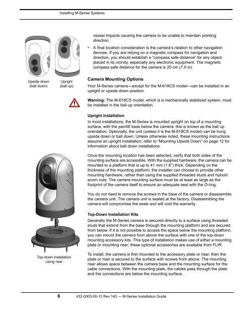
Upside down<br />
(ball down)<br />
Installing M-<strong>Series</strong> <strong>Systems</strong><br />
Upright<br />
(ball up)<br />
Top-down installation<br />
using riser<br />
vessel impacts causing the camera to be unable to maintain pointing<br />
direction.<br />
• A final location consideration is the camera’s relation to other navigation<br />
devices. If you are relying on a magnetic compass for navigation and<br />
direction, you should establish a “compass safe distance” for any object<br />
placed in its vicinity, especially any electronic equipment. The magnetic<br />
compass safe distance for the camera is 20 cm (7.9 in).<br />
Camera Mounting Options<br />
Your M-<strong>Series</strong> camera—except for the M-618CS model—can be installed in an<br />
upright or upside down position.<br />
Warning: The M-618CS model, which is a mechanically stabilized system, must<br />
be installed in the ball-up orientation.<br />
Upright <strong>Installation</strong><br />
In most installations, the M-<strong>Series</strong> is mounted upright on top of a mounting<br />
surface, with the pan/tilt base below the camera; this is known as the ball up<br />
orientation. Optionally, the unit (unless it is the M-618CS model) can be hung<br />
upside down or ball down. Unless otherwise noted, these mounting instructions<br />
assume an upright installation; refer to “Mounting Upside Down” on page <strong>12</strong> for<br />
information about ball down installations.<br />
Once the mounting location has been selected, verify that both sides of the<br />
mounting surface are accessible. With the supplied hardware, the camera can be<br />
mounted to a platform that is up to 41 mm (1.6”) thick. Depending on the<br />
thickness of the mounting platform, the installer can choose to provide other<br />
mounting hardware, rather than using the supplied threaded studs and nylock/<br />
acorn nuts. The camera mounting surface must be at least as large as the<br />
footprint of the camera itself to ensure an adequate seal with the O-ring.<br />
You do not need to remove the screws in the base of the camera or disassemble<br />
the camera unit. The camera unit is sealed at the factory. Disassembling the<br />
camera will compromise the seals and will void the warranty.<br />
Top-Down <strong>Installation</strong> Kits<br />
Generally the M-<strong>Series</strong> camera is secured directly to a surface using threaded<br />
studs that extend from the base through the mounting platform and are secured<br />
from below. If it is not possible to access the space below the mounting platform,<br />
you can mount the camera from above the surface with one of the top-down<br />
mounting accessory kits. This type of installation makes use of either a mounting<br />
plate or mounting riser; these optional accessories are available from <strong>FLIR</strong>.<br />
To install, the camera is first mounted to the accessory plate or riser, then the<br />
plate or riser is secured to the surface with screws from above. The mounting<br />
riser allows space between the camera base and the mounting surface for the<br />
cable connections. With the mounting plate, the cables pass through the plate<br />
and the connections are below the mounting surface.<br />
8 <strong>432</strong>-<strong><strong>00</strong>03</strong>-<strong>00</strong>-<strong>12</strong> <strong>Rev</strong> <strong>140</strong> — M-<strong>Series</strong> <strong>Installation</strong> Guide