432-0003-00-12 Rev 140 M-Series Installation ... - FLIR Systems
432-0003-00-12 Rev 140 M-Series Installation ... - FLIR Systems
432-0003-00-12 Rev 140 M-Series Installation ... - FLIR Systems

You also want an ePaper? Increase the reach of your titles
YUMPU automatically turns print PDFs into web optimized ePapers that Google loves.
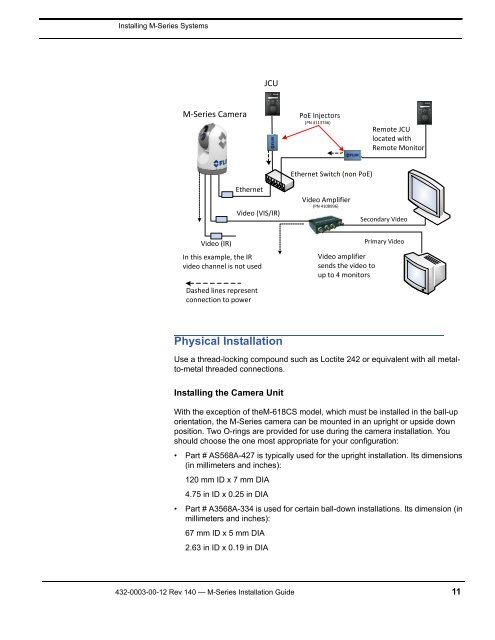
Installing M-<strong>Series</strong> <strong>Systems</strong><br />
M-<strong>Series</strong> Camera<br />
Video (IR)<br />
Ethernet<br />
JCU<br />
Video (VIS/IR)<br />
In this example, the IR<br />
video channel is not used<br />
Dashed lines represent<br />
connection to power<br />
Physical <strong>Installation</strong><br />
Use a thread-locking compound such as Loctite 242 or equivalent with all metalto-metal<br />
threaded connections.<br />
Installing the Camera Unit<br />
PoE Injectors<br />
(PN 4113746)<br />
Ethernet Switch (non PoE)<br />
Video Amplifier<br />
(PN 4108996)<br />
Video amplifier<br />
sends the video to<br />
up to 4 monitors<br />
Remote JCU<br />
located with<br />
Remote Monitor<br />
Secondary Video<br />
Primary Video<br />
With the exception of theM-618CS model, which must be installed in the ball-up<br />
orientation, the M-<strong>Series</strong> camera can be mounted in an upright or upside down<br />
position. Two O-rings are provided for use during the camera installation. You<br />
should choose the one most appropriate for your configuration:<br />
• Part # AS568A-427 is typically used for the upright installation. Its dimensions<br />
(in millimeters and inches):<br />
<strong>12</strong>0 mm ID x 7 mm DIA<br />
4.75 in ID x 0.25 in DIA<br />
• Part # A3568A-334 is used for certain ball-down installations. Its dimension (in<br />
millimeters and inches):<br />
67 mm ID x 5 mm DIA<br />
2.63 in ID x 0.19 in DIA<br />
<strong>432</strong>-<strong><strong>00</strong>03</strong>-<strong>00</strong>-<strong>12</strong> <strong>Rev</strong> <strong>140</strong> — M-<strong>Series</strong> <strong>Installation</strong> Guide 11