432-0003-00-12 Rev 140 M-Series Installation ... - FLIR Systems
432-0003-00-12 Rev 140 M-Series Installation ... - FLIR Systems
432-0003-00-12 Rev 140 M-Series Installation ... - FLIR Systems

You also want an ePaper? Increase the reach of your titles
YUMPU automatically turns print PDFs into web optimized ePapers that Google loves.
Installing M-<strong>Series</strong> <strong>Systems</strong><br />
As an alternative to the mounting O-ring, you can use a marine-grade sealant<br />
such as 3M 52<strong>00</strong> or the equivalent.<br />
Mounting Upright<br />
Caution: The cable connectors terminating the pigtail cables on the camera are<br />
not sealed connectors; therefore, appropriate sealing steps are needed to protect<br />
the connections and the camera.<br />
Caution: Before drilling holes, ensure you have first followed the steps outlined<br />
in the planning section (page 7). For example, it is important to test the unit at the<br />
planned installation location with typical vessel electronics active prior to<br />
mounting the camera.<br />
Using the template supplied with the camera as a guide, mark the location of the<br />
holes for mounting the camera. Make sure the template is oriented properly<br />
relative to the bow of the vessel; observe that the forward direction is reversed for<br />
the ball-down installation. If the template is printed, be sure it is printed to scale<br />
so the dimensions are correct. If you are using one of the top-down installation<br />
kits, the riser or plate itself should be used as a template for the location of the<br />
drill holes and cable access hole.<br />
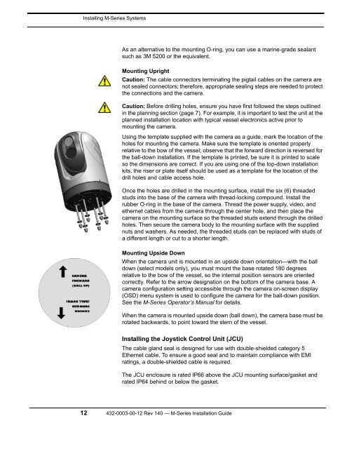
Once the holes are drilled in the mounting surface, install the six (6) threaded<br />
studs into the base of the camera with thread-locking compound. Install the<br />
rubber O-ring in the base of the camera. Thread the power supply, video, and<br />
ethernet cables from the camera through the center hole, and then place the<br />
camera on the mounting surface so the threaded studs extend through the drilled<br />
holes. Then secure the camera body to the mounting surface with the supplied<br />
nuts and washers. As needed, the threaded studs can be replaced with studs of<br />
a different length or cut to a shorter length.<br />
Mounting Upside Down<br />
When the camera unit is mounted in an upside down orientation—with the ball<br />
down (select models only), you must mount the base rotated 180 degrees<br />
relative to the bow of the vessel, so the internal position sensors are oriented<br />
correctly. Refer to the arrow designation on the bottom of the camera base. A<br />
camera configuration setting accessible through the camera on-screen display<br />
(OSD) menu system is used to configure the camera for the ball-down position.<br />
See the M-<strong>Series</strong> Operator’s Manual for details.<br />
When the camera is mounted upside down (ball down), the camera base must be<br />
rotated backwards, to point toward the stern of the vessel.<br />
Installing the Joystick Control Unit (JCU)<br />
The cable gland seal is designed for use with double-shielded category 5<br />
Ethernet cable. To ensure a good seal and to maintain compliance with EMI<br />
ratings, a double-shielded cable is required.<br />
The JCU enclosure is rated IP66 above the JCU mounting surface/gasket and<br />
rated IP64 behind or below the gasket.<br />
<strong>12</strong> <strong>432</strong>-<strong><strong>00</strong>03</strong>-<strong>00</strong>-<strong>12</strong> <strong>Rev</strong> <strong>140</strong> — M-<strong>Series</strong> <strong>Installation</strong> Guide