Product News - Embedded-Control-Europe.com
Product News - Embedded-Control-Europe.com
Product News - Embedded-Control-Europe.com
Create successful ePaper yourself
Turn your PDF publications into a flip-book with our unique Google optimized e-Paper software.
COTS<br />
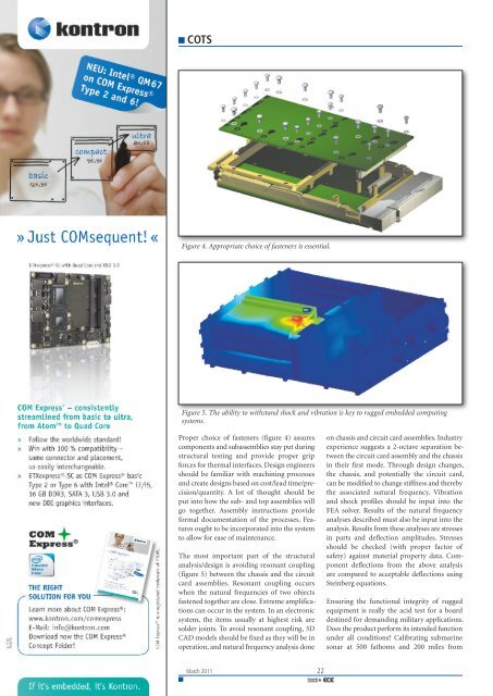
Figure 4. Appropriate choice of fasteners is essential.<br />
Figure 5. The ability to withstand shock and vibration is key to rugged embedded <strong>com</strong>puting<br />
systems.<br />
Proper choice of fasteners (figure 4) assures<br />
<strong>com</strong>ponents and subassemblies stay put during<br />
structural testing and provide proper grip<br />
forces for thermal interfaces. Design engineers<br />
should be familiar with machining processes<br />
and create designs based on cost/lead time/precision/quantity.<br />
A lot of thought should be<br />
put into how the sub- and top assemblies will<br />
go together. Assembly instructions provide<br />
formal documentation of the processes. Features<br />
ought to be incorporated into the system<br />
to allow for ease of maintenance.<br />
The most important part of the structural<br />
analysis/design is avoiding resonant coupling<br />
(figure 5) between the chassis and the circuit<br />
card assemblies. Resonant coupling occurs<br />
when the natural frequencies of two objects<br />
fastened together are close. Extreme amplifications<br />
can occur in the system. In an electronic<br />
system, the items usually at highest risk are<br />
solder joints. To avoid resonant coupling, 3D<br />
CAD models should be fixed as they will be in<br />
operation, and natural frequency analysis done<br />
March 2011 22<br />
on chassis and circuit card assemblies. Industry<br />
experience suggests a 2-octave separation between<br />
the circuit card assembly and the chassis<br />
in their first mode. Through design changes,<br />
the chassis, and potentially the circuit card,<br />
can be modified to change stiffness and thereby<br />
the associated natural frequency. Vibration<br />
and shock profiles should be input into the<br />
FEA solver. Results of the natural frequency<br />
analyses described must also be input into the<br />
analysis. Results from these analyses are stresses<br />
in parts and deflection amplitudes. Stresses<br />
should be checked (with proper factor of<br />
safety) against material property data. Component<br />
deflections from the above analysis<br />
are <strong>com</strong>pared to acceptable deflections using<br />
Steinberg equations.<br />
Ensuring the functional integrity of rugged<br />
equipment is really the acid test for a board<br />
destined for demanding military applications.<br />
Does the product perform its intended function<br />
under all conditions? Calibrating submarine<br />
sonar at 500 fathoms and 200 miles from


