An absolute electrometer for the physics laboratory
An absolute electrometer for the physics laboratory
An absolute electrometer for the physics laboratory

You also want an ePaper? Increase the reach of your titles
YUMPU automatically turns print PDFs into web optimized ePapers that Google loves.
F EATURES<br />
www.iop.org/journals/physed<br />
<strong>An</strong> <strong>absolute</strong> <strong>electrometer</strong> <strong>for</strong> <strong>the</strong><br />
<strong>physics</strong> <strong>laboratory</strong><br />
S Straulino and A Cartacci<br />
Dipartimento di Fisica dell’Università di Firenze, Via G Sansone, 1 50019 Sesto Fiorentino,<br />
Italy<br />
E-mail: straulino@fi.infn.it<br />
Abstract<br />
A low-cost, easy-to-use <strong>absolute</strong> <strong>electrometer</strong> is presented: two thin metallic<br />
plates and an electronic balance, usually available in a <strong>laboratory</strong>, are used.<br />
We report on <strong>the</strong> very good per<strong>for</strong>mance of <strong>the</strong> device that allows precise<br />
measurements of <strong>the</strong> <strong>for</strong>ce acting between two charged plates.<br />
Introduction<br />
The <strong>electrometer</strong> is a device which is used to<br />
measure electric potentials; it is <strong>absolute</strong> when<br />
<strong>the</strong> potentials are evaluated through <strong>the</strong> direct<br />
measurement of a <strong>for</strong>ce and consequently no<br />
previous calibration, using a known voltage,<br />
is necessary. The <strong>absolute</strong> <strong>electrometer</strong> was<br />
first proposed by Lord Kelvin (an interesting<br />
description of this instrument was given by<br />
Maxwell [1]). We realized an up-to-date version<br />
of <strong>the</strong> <strong>absolute</strong> <strong>electrometer</strong> with an electronic<br />
precision balance and two circular metallic plates.<br />
The classical <strong>absolute</strong> <strong>electrometer</strong><br />
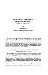
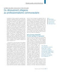
Lord Kelvin’s instrument is schematically sketched<br />
in figure 1: it can be imagined as a two-arm balance<br />
connected to a parallel-plate capacitor. The<br />
lower plate of <strong>the</strong> capacitor is fixed and attached to<br />
<strong>the</strong> table by means of an insulating rod. The upper<br />
plate, hung up by a wire and connected to <strong>the</strong> balance’s<br />
arm, is equilibrated using some weights on<br />
<strong>the</strong> opposite pan of <strong>the</strong> balance. The lower plate<br />
is taken to an unknown voltage. Then opposite<br />
charges appear on <strong>the</strong> facing plate because of electrostatic<br />
induction. Positive and negative charges<br />
generate a <strong>for</strong>ce that produces a small rotation of<br />
<strong>the</strong> balance’s arm. The previous equilibrium can<br />
GR P1<br />
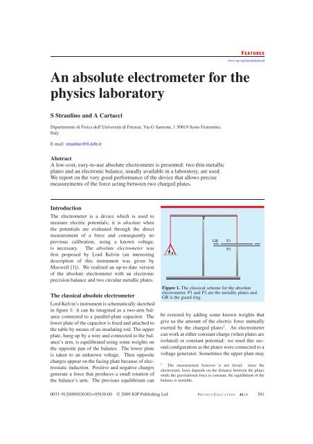
Figure 1. The classical scheme <strong>for</strong> <strong>the</strong> <strong>absolute</strong><br />
<strong>electrometer</strong>. P1 and P2 are <strong>the</strong> metallic plates and<br />
GR is <strong>the</strong> guard ring.<br />
be restored by adding some known weights that<br />
give us <strong>the</strong> amount of <strong>the</strong> electric <strong>for</strong>ce mutually<br />
exerted by <strong>the</strong> charged plates 1 . <strong>An</strong> <strong>electrometer</strong><br />
can work at ei<strong>the</strong>r constant charge (when plates are<br />
isolated) or constant potential: we used this second<br />
configuration as <strong>the</strong> plates were connected to a<br />
voltage generator. Sometimes <strong>the</strong> upper plate may<br />
1 The measurement however is not trivial: since <strong>the</strong><br />
electrostatic <strong>for</strong>ce depends on <strong>the</strong> distance between <strong>the</strong> plates<br />
while <strong>the</strong> gravitational <strong>for</strong>ce is constant, <strong>the</strong> equilibrium of <strong>the</strong><br />
balance is unstable.<br />
0031-9120/09/030301+05$30.00 © 2009 IOP Publishing Ltd P HYSICS E DUCATION 44 (3) 301<br />
P2
S Straulino and A Cartacci<br />
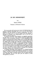
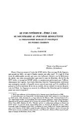
Figure 2. A photograph of <strong>the</strong> <strong>electrometer</strong>. The upper plate is sustained by two microscope slides, glued on <strong>the</strong><br />
disc and laid on a pair of adjustable <strong>laboratory</strong> jacks. The o<strong>the</strong>r disc is laid on <strong>the</strong> pan of <strong>the</strong> balance through an<br />
insulating support. The high-voltage generator is not shown in <strong>the</strong> picture.<br />
be surrounded by a guard ring, kept at <strong>the</strong> same potential<br />
as <strong>the</strong> internal plate: it can be used to reduce<br />
<strong>the</strong> fringing effects. Different aspects of <strong>the</strong> <strong>electrometer</strong><br />
have already been discussed within educational<br />
articles [2–4].<br />
For a calculation of <strong>the</strong> <strong>for</strong>ce acting between<br />
<strong>the</strong> plates, let us review some basic relationships of<br />
electromagnetism. The capacitance of a charged<br />
conductor body, far away o<strong>the</strong>rs, is defined as <strong>the</strong><br />
ratio between its charge Q and its potential V :<br />
C = Q<br />
V .<br />
In <strong>the</strong> case of a parallel-plate, infinitely large<br />
capacitor in vacuum, Q is <strong>the</strong> <strong>absolute</strong> value<br />
of <strong>the</strong> charge present on both plates and V <strong>the</strong><br />
potential difference between <strong>the</strong>m. In this case C<br />
can also be written by means of <strong>the</strong> geometrical<br />
characteristics of <strong>the</strong> capacitor in <strong>the</strong> following<br />
<strong>for</strong>m:<br />
S<br />
C = ε0 , (1)<br />
d<br />
S being <strong>the</strong> surface of each plate and d <strong>the</strong> distance<br />
between <strong>the</strong>m.<br />
The energy stored in <strong>the</strong> capacitor is given by<br />
W = 1<br />
2 CV2 = 1<br />
2 ε0<br />
S<br />
d<br />
V 2<br />
and <strong>the</strong> <strong>for</strong>ce is obtained by calculating <strong>the</strong><br />
derivative of <strong>the</strong> previous quantity with respect to<br />
d:<br />
F =−<br />
ε0SV 2<br />
2d 2<br />
. (2)<br />
The potential difference V can be written as<br />
�<br />
2 |F|<br />
V = d<br />
ε0S .<br />
When an insulating material is filling <strong>the</strong><br />
space between <strong>the</strong> plates, <strong>the</strong> <strong>for</strong>ce F depends on<br />
εr, <strong>the</strong> dielectric constant of <strong>the</strong> material. The<br />
<strong>for</strong>ce measured in <strong>the</strong> air will be, to an excellent<br />
approximation, <strong>the</strong> same as that measured in<br />
vacuum because εr = 1.0006 <strong>for</strong> <strong>the</strong> atmosphere<br />
in standard conditions.<br />
Construction and setup in our <strong>laboratory</strong><br />
We commissioned from a mechanical workshop<br />
several circular aluminium plates with identical<br />
diameters (300 mm) and various thicknesses (3,<br />
4, 5 mm). A couple of discs were selected <strong>for</strong><br />
<strong>the</strong> device on <strong>the</strong> basis of <strong>the</strong> best planarity 2 .<br />
A thin copper wire was attached to each plate<br />
<strong>for</strong> <strong>the</strong> electrical connections. The first disc was<br />
laid on a plastic support, laid in turn on <strong>the</strong> pan<br />
of <strong>the</strong> balance: it was electrically connected to<br />
ground. We set <strong>the</strong> plate horizontal by adjusting<br />
<strong>the</strong> screws on <strong>the</strong> balance’s base. The o<strong>the</strong>r disc<br />
was suspended by two insulating supports exactly<br />
above <strong>the</strong> first one, at a small distance d (figure 2).<br />
2 At first we used two stainless steel discs, 1 mm thick. We<br />
realized after a few measurements that <strong>the</strong>y were not planar,<br />
because <strong>the</strong>y were too thin (a good planarity—within 0.1 mm—<br />
is not easily achievable <strong>for</strong> thin metal plates). Then we used a<br />
light metal such as aluminium to fall within <strong>the</strong> range of <strong>the</strong><br />
balance (1500 g) with a greater thickness of <strong>the</strong> disc. Besides,<br />
<strong>the</strong> use of a non-ferrous material helps students by removing<br />
any source of misunderstanding about a supposed magnetic<br />
origin of <strong>the</strong> attraction between <strong>the</strong> plates.<br />
302 P HYSICS E DUCATION May 2009
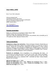
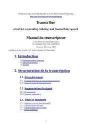
Figure 3. The height gauge used to determine <strong>the</strong><br />
positions of <strong>the</strong> discs.<br />
A potential difference produced by a highvoltage<br />
(up to 2000 V) DC generator was applied<br />
to <strong>the</strong> plates. The sensitivity of <strong>the</strong> balance<br />
(0.01 g) was enough <strong>for</strong> us to see visible effects<br />
when voltages were larger than about 100 V. <strong>An</strong><br />
electronic precision balance is suitable <strong>for</strong> this<br />
purpose as <strong>the</strong> pan is practically motionless and<br />
consequently <strong>the</strong> distance between <strong>the</strong> plates is<br />
always <strong>the</strong> same, allowing a direct determination<br />
of <strong>the</strong> <strong>for</strong>ce without any instability or oscillation 3 .<br />
A Plexiglass box covered <strong>the</strong> <strong>electrometer</strong>: it<br />
was intended not only <strong>for</strong> safety reasons (<strong>the</strong><br />
high voltage is obviously dangerous 4 )butalsoto<br />
avoid unexpected movements of <strong>the</strong> surrounding<br />
air possibly influencing <strong>the</strong> measurements. The<br />
distance between <strong>the</strong> plates was measured using<br />
a height gauge (figure 3), with a sensitivity of<br />
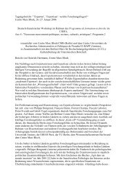
0.02 mm, at four equidistant points A, B, C, D on<br />
<strong>the</strong> disc (figure 4), to obtain a mean distance with<br />
a small level of uncertainty.<br />
3 The weight of both <strong>the</strong> lower disc and <strong>the</strong> plastic support<br />
can be automatically included as a tare. Readings are negative<br />
numbers, <strong>the</strong> electrostatic <strong>for</strong>ce being attractive.<br />
4 As a fur<strong>the</strong>r caution, <strong>the</strong> current output of <strong>the</strong> generator<br />
was limited to 100 μA. This does not represent a restrictive<br />
condition <strong>for</strong> <strong>the</strong> use of <strong>the</strong> <strong>electrometer</strong>, since in stationary<br />
conditions <strong>the</strong> nominal current flow is zero.<br />
<strong>An</strong> <strong>absolute</strong> <strong>electrometer</strong> <strong>for</strong> <strong>the</strong> <strong>physics</strong> <strong>laboratory</strong><br />
D<br />
A<br />
Figure 4. Labels on <strong>the</strong> disc to measure <strong>the</strong> distance<br />
from <strong>the</strong> o<strong>the</strong>r plate.<br />
Table 1. Three different distances from <strong>the</strong> upper and<br />
lower discs, as measured by <strong>the</strong> height gauge.<br />
Label Distance (mm) Mean (mm)<br />
No 1 A 18.30 18.4 ± 0.1<br />
B 18.40<br />
C 18.54<br />
D 18.30<br />
No 2 A 12.16 12.1 ± 0.2<br />
B 12.10<br />
C 11.90<br />
D 12.22<br />
No 3 A 6.14 6.1 ± 0.1<br />
B 6.04<br />
C 6.12<br />
D 6.10<br />
Results<br />
In this section we report some measurements taken<br />
with <strong>the</strong> device. The <strong>electrometer</strong> works very<br />
well, showing results that are always reproducible.<br />
We report three sets of measurements at different<br />
distances <strong>for</strong> voltages ranging from 0 to 2000 V. In<br />
table 1 <strong>the</strong> distances between <strong>the</strong> upper and lower<br />
discs are reported: from <strong>the</strong> measurements taken<br />
at different points we calculated <strong>the</strong> mean and <strong>the</strong><br />
maximum difference from <strong>the</strong> mean. In table 2 <strong>the</strong><br />
weight 5 measured by <strong>the</strong> balance <strong>for</strong> every voltage<br />
can be found.<br />
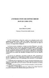
In figure 5 <strong>the</strong> weight is reported versus <strong>the</strong><br />
squared voltage and a law of direct proportionality<br />
can be verified. A linear interpolation of <strong>the</strong><br />
5 The <strong>for</strong>ce read on <strong>the</strong> balance was in gram-<strong>for</strong>ce while, using<br />
<strong>the</strong> international system of units, <strong>the</strong> <strong>for</strong>ce of equation (2) is<br />
expressed in newtons.<br />
May 2009 P HYSICS E DUCATION 303<br />
C<br />
B
S Straulino and A Cartacci<br />
weight (g)<br />
Table 2. Readings of <strong>the</strong> balance at various voltages <strong>for</strong> three distances between <strong>the</strong> plates.<br />
Voltage (V) 0 200 400 600 800 1000 1200 1400 1600 1800 2000<br />
No 1 Weight (g) 0 0 −0.01 −0.03 −0.06 −0.09 −0.13 −0.18 −0.24 −0.31 −0.38<br />
No 2 Weight (g) 0 −0.01 −0.04 −0.08 −0.15 −0.23 −0.33 −0.45 −0.58 −0.74 −0.91<br />
No 3 Weight (g) 0 −0.03 −0.14 −0.32 −0.57 −0.90 −1.30 −1.77 −2.31 −2.93 −3.61<br />
0<br />
–0.5<br />
–1.0<br />
–1.5<br />
–2.0<br />
–2.5<br />
–3.0<br />
d = 18.4 mm (fit)<br />
d = 11.8 mm (fit)<br />
–3.5<br />
d = 5.9 mm (fit)<br />
–4.0<br />
0 1 2 3 4<br />
squared voltage (kV 2 )<br />
Figure 5. The measured weight, reported as a<br />
function of <strong>the</strong> squared voltage <strong>for</strong> three different<br />
distances, and <strong>the</strong> linear fits. The experimental error<br />
bars are smaller than <strong>the</strong> point size. The dotted curves<br />
represent <strong>the</strong> <strong>the</strong>oretical behaviour if <strong>the</strong> measured<br />
distances are used. For <strong>the</strong> greatest distance, <strong>the</strong> two<br />
lines are superimposed.<br />
points allows an a posteriori determination of<br />
<strong>the</strong> distance of <strong>the</strong> plates that is written in <strong>the</strong><br />
graph. The agreement with <strong>the</strong> corresponding<br />
measured distances is quite good. In <strong>the</strong> figure<br />
<strong>the</strong> <strong>the</strong>oretical straight line corresponding to <strong>the</strong><br />
value of <strong>the</strong> measured distances is also shown.<br />
The small discrepancy between measured and<br />
fitted distances can be attributed to <strong>the</strong> fringing<br />
effects, which were not included in our analysis,<br />
and to <strong>the</strong> imperfect alignment of <strong>the</strong> plates. In<br />
figure 6 <strong>the</strong> difference of each measured weight<br />
from <strong>the</strong> interpolating straight line is reported.<br />
The instrument allows also a measurement of <strong>the</strong><br />
applied voltage through <strong>the</strong> value of <strong>the</strong> <strong>for</strong>ce<br />
(<strong>absolute</strong> <strong>electrometer</strong>). The discrepancy is of <strong>the</strong><br />
order of 2% <strong>for</strong> voltages greater than 1000 V (as<br />
measured weight – fitted weight (g)<br />
0.02<br />
0<br />
–0.02<br />
0.02<br />
0<br />
–0.02<br />
0.02<br />
0<br />
–0.02<br />
0 0.5 1.0 1.5 2.0<br />
0 0.5 1.0 1.5 2.0<br />
0 0.5 1.0 1.5 2.0<br />
voltage (kV)<br />
Figure 6. Differences between <strong>the</strong> measured weight<br />
and linear fit, reported as a function of <strong>the</strong> voltage,<br />
<strong>for</strong> <strong>the</strong> same measurements as in figure 5. <strong>An</strong><br />
uncertainty of 0.005 g (half <strong>the</strong> sensitivity of <strong>the</strong><br />
balance) is assumed <strong>for</strong> each point.<br />
can be deduced from table 2) and depends on <strong>the</strong><br />
uncertainty of <strong>the</strong> distance and <strong>the</strong> sensitivity of<br />
<strong>the</strong> balance. A better precision could be obtained<br />
by means of a more expensive balance with a<br />
sensitivity of 1 mg. In any case, <strong>the</strong> instrument<br />
is not designed <strong>for</strong> measuring an unknown voltage<br />
in our <strong>laboratory</strong> but as an experiment which can<br />
easily indicate <strong>the</strong> existence of <strong>the</strong> <strong>for</strong>ce between<br />
<strong>the</strong> plates and verify its dependence on <strong>the</strong> applied<br />
voltage.<br />
Note on <strong>the</strong> fringing effects<br />
The <strong>for</strong>mulae describing <strong>the</strong> parallel-plate capacitor<br />
that we have used, assume a constant electric<br />
field inside <strong>the</strong> capacitor, regardless of fringing<br />
effects. Many articles can be found in <strong>the</strong> literature<br />
(<strong>for</strong> example [1, 5, 6]) where <strong>the</strong> fringing effects<br />
are discussed and often a guard ring is introduced<br />
304 P HYSICS E DUCATION May 2009
in experimental devices to preserve <strong>the</strong> uni<strong>for</strong>mity<br />
of <strong>the</strong> field near <strong>the</strong> edges also.<br />
There<strong>for</strong>e we expected that <strong>the</strong> deviation<br />
from <strong>the</strong> ideal case might become significant <strong>for</strong><br />
increasing distances of <strong>the</strong> plates. However, in our<br />
measurements we find only a small discrepancy<br />
between <strong>the</strong> parallel-plate description and <strong>the</strong><br />
results. This matter has been discussed by<br />
Hale [4, 7]: he showed that <strong>the</strong> corrections due to<br />
<strong>the</strong> fringing effects are always quite small when<br />
measuring <strong>the</strong> <strong>for</strong>ce between facing plates. In<br />
fact <strong>the</strong> difference between <strong>the</strong> real capacitance<br />
and <strong>the</strong> ideal one (equation (1)) is approximately<br />
independent of <strong>the</strong> plate separation <strong>for</strong> a limited<br />
range of distances and barely affects <strong>the</strong> attractive<br />
<strong>for</strong>ce (equation (2)) connected with <strong>the</strong> derivative<br />
of <strong>the</strong> capacitance.<br />
Educational remarks<br />
The instrument described was included in <strong>the</strong><br />
<strong>physics</strong> <strong>laboratory</strong> of <strong>the</strong> OpenLab project of<br />
<strong>the</strong> Florence University, partially supported by<br />
<strong>the</strong> Italian Instruction Ministry in <strong>the</strong> context of<br />
<strong>the</strong> ‘Lauree Scientifiche’ project. Every year<br />
many exercises in <strong>the</strong> <strong>laboratory</strong> are organized.<br />
The high-school students who attend <strong>the</strong> activity,<br />
divided into small groups, assemble and use<br />
<strong>the</strong> apparatus under <strong>the</strong> supervision of university<br />
researchers. The <strong>absolute</strong> <strong>electrometer</strong> has been<br />
presented to some classes visiting this <strong>laboratory</strong>:<br />
it has proved to be of great educational interest in<br />
<strong>the</strong> high school. Students immediately perceive<br />
<strong>the</strong> presence of a <strong>for</strong>ce between <strong>the</strong> plates of <strong>the</strong><br />
capacitor and <strong>the</strong>y can appreciate <strong>the</strong> simplicity<br />
and <strong>the</strong> accuracy of <strong>the</strong> measurements. Usually<br />
in high-school laboratories qualitative experiments<br />
on <strong>the</strong> electric charge are per<strong>for</strong>med: here, in<br />
contrast, quantitative measurements can be easily<br />
taken. Feedback on <strong>the</strong> activity is usually obtained<br />
<strong>An</strong> <strong>absolute</strong> <strong>electrometer</strong> <strong>for</strong> <strong>the</strong> <strong>physics</strong> <strong>laboratory</strong><br />
from <strong>the</strong> teachers who are present in our <strong>laboratory</strong><br />
toge<strong>the</strong>r with <strong>the</strong>ir classes.<br />
Acknowledgment<br />
We wish to thank Professor Oscar Adriani and Dr<br />
Cecilia Gambi <strong>for</strong> fruitful discussions concerning<br />
<strong>the</strong> subject of this work.<br />
Received 8 January 2009, in final <strong>for</strong>m 13 February 2009<br />
doi:10.1088/0031-9120/44/3/011<br />
References<br />
[1] Maxwell J K 1873 A Treatise on Electricity and<br />
Magnetism (Ox<strong>for</strong>d: Clarendon)<br />
[2] Cross J D and Smalley C 1969 Electrical<br />
measurements with an electronic micro<strong>for</strong>ce<br />
balance J. Phys. E: Sci. Instrum. 2 633<br />
[3] Metz R N 1973 The <strong>absolute</strong> <strong>electrometer</strong> revisited<br />
Am.J.Phys.41 1170–5<br />
[4] Hale D P 1978 A measurement of electrostatic<br />
<strong>for</strong>ce Phys. Educ. 13 344–7<br />
[5] Wintle H J 1986 Capacitor edge corrections IEEE<br />
Trans. Electr. Insul. EI-21 361–3<br />
[6] Carlson G T and Illman B L 1994 The circular disk<br />
parallel plate capacitor Am. J. Phys.<br />
62 1099–105<br />
[7] Hale D P 1978 Fringe capacitance of a<br />
parallel-plate capacitor Phys. Educ. 13 446–8<br />
Samuele Straulino graduated at Florence<br />
University in 1999. In 2003 he was<br />
awarded a PhD in <strong>physics</strong> from Bologna<br />
University; his <strong>the</strong>sis was on cosmic-ray<br />
<strong>physics</strong>. Since 2004, thanks to a<br />
post-doctoral fellowship, he has been<br />
working on educational <strong>physics</strong> at<br />
Florence University.<br />
<strong>An</strong>namaria Cartacci was Associate<br />
Professor at Florence University until<br />
2002, where she taught elementary<br />
particle <strong>physics</strong>. She is <strong>the</strong> author of<br />
numerous papers in international<br />
journals. Now retired, she remains<br />
involved in <strong>physics</strong> popularization and is<br />
responsible <strong>for</strong> <strong>laboratory</strong> courses <strong>for</strong><br />
teachers working in high schools.<br />
May 2009 P HYSICS E DUCATION 305