Protocol Design and Implementation of Vehicular Ad-hoc Networks
Protocol Design and Implementation of Vehicular Ad-hoc Networks
Protocol Design and Implementation of Vehicular Ad-hoc Networks
Create successful ePaper yourself
Turn your PDF publications into a flip-book with our unique Google optimized e-Paper software.
<strong>Protocol</strong> <strong>Design</strong> <strong>and</strong> <strong>Implementation</strong> <strong>of</strong> <strong>Vehicular</strong><br />
<strong>Ad</strong>-<strong>hoc</strong> <strong>Networks</strong><br />
Ali Haroon Babri, Sayed Aziz, Khalid Liaqat <strong>and</strong> Muhammad Talha<br />
Electrical Engineering Dept, University <strong>of</strong> Engineering <strong>and</strong> Technology, Lahore<br />
Abstract- <strong>Vehicular</strong> ad-<strong>hoc</strong> networks (VANETs)<br />
incorporate vehicle-to-vehicle <strong>and</strong> vehicle-toinfrastructure<br />
communication to provide a host <strong>of</strong><br />
applications which aim to provide, among other<br />
things, a reduction in traffic congestion, accident<br />
detection <strong>and</strong> entertainment. In this paper, we<br />
describe a small scale experimental model in<br />
which we have implemented two major<br />
applications <strong>of</strong> VANETs i.e. Congestion detection<br />
<strong>and</strong> Emergency Notification. We first design the<br />
entire protocol for communication <strong>and</strong> then build<br />
the hardware modules - Roadside <strong>and</strong> vehicular<br />
modules, with the former planted at stationary<br />
locations <strong>and</strong> the later mounted on moving<br />
vehicles.<br />
Keywords – Vehicle to vehicle<br />
communication, Vehicle to infrastructure,<br />
congestion detection, emergency warning.<br />
I. INTRODUCTION<br />
<strong>Vehicular</strong> ad-<strong>hoc</strong> <strong>Networks</strong> (VANETs), a<br />
subset <strong>of</strong> wireless mesh networks, is a developing<br />
technology which aims to create a mobile network<br />
using cars as nodes [1]. A VANET behaves as an<br />
ordinary wireless network would with the<br />
additional challenge <strong>of</strong> the mobility <strong>of</strong> nodes [2].<br />
The network must be continuously reconfigured<br />
as vehicles move around, with some leaving <strong>and</strong><br />
others joining the network from time to time. A<br />
major issue with VANETs is that the technology<br />
must be st<strong>and</strong>ardised so as to enable vehicles to<br />
communicate with each other <strong>and</strong> with<br />
infrastructure according to a defined protocol.<br />
This initial difficulty is bound to pay dividends in<br />
the end with a vast multitude <strong>of</strong> potential<br />
© ICCIT 2012 718<br />
applications providing various services for the<br />
comfort <strong>and</strong> convenience <strong>of</strong> the driver <strong>and</strong><br />
passengers.<br />
<strong>Vehicular</strong> <strong>Networks</strong>, being a relatively new<br />
field with a very large potential for development<br />
<strong>and</strong> numerous possible applications, have<br />
attracted the attention <strong>of</strong> many researchers<br />
worldwide. Abdalla et al. [3] discuss current<br />
trends in VANETs, <strong>and</strong> an effective congestion<br />
control scheme was proposed in [4]. In [3] <strong>and</strong> [5]<br />
routing protocols for VANETs are discussed. The<br />
Car 2 Car Communication consortium, founded<br />
by leading European auto manufacturers aspires<br />
to establish a European st<strong>and</strong>ard that all<br />
manufacturers will conform to [6].<br />
II. SYSTEM OVERVIEW<br />
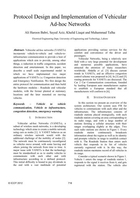
In this section we present an overview <strong>of</strong> the<br />
system architecture. Our system uses FM for<br />
vehicles to communicate with each other <strong>and</strong> the<br />
infrastructure. The infrastructure consists <strong>of</strong><br />
roadside stations placed strategically, with each<br />
roadside station covering an area corresponding to<br />
its radio range, <strong>and</strong> with a large number <strong>of</strong><br />
stations forming a cellular structure with their<br />
ranges overlapping slightly at the edges. Two<br />
such radio stations are shown in Figure 1. Every<br />
roadside station continuously broadcasts<br />
information about the region as well as its identity<br />
<strong>and</strong> prompts vehicles in range to establish contact<br />
with it. The Roadside Station then enters each<br />
vehicle that responds in its list <strong>of</strong> vehicles<br />
currently registered with it. In this way, the<br />
roadside station maintains record <strong>of</strong> all vehicles in<br />
its range.<br />
Consider a typical scenario shown in Figure 1.<br />
Vehicle 1 enters the range <strong>of</strong> roadside station 1,<br />
responds to the signal it receives from it, <strong>and</strong> gets<br />
registered with the station. The vehicle also
eceives information about the region it has just<br />
entered into such as the number <strong>of</strong> vehicles in the<br />
vicinity <strong>and</strong> whether there are any accidents<br />
nearby. If the vehicle finds the vehicle count in<br />
the region to be unacceptable, indicating<br />
congestion, it may decide whether to continue<br />
down the same path or to take an alternate route,<br />
shown by the curved arrow.<br />
Range <strong>of</strong> station 2<br />
Vehicle 2<br />
Vehicle 1<br />
Range <strong>of</strong> station 1<br />
Figure 1 – System Overview<br />
Roadside<br />
station 2<br />
Roadside<br />
station 1<br />
Congested area<br />
III. COMMUNICATION PROTOCOL<br />
A. Communication Overview<br />
The protocol for communication is a modified<br />
version <strong>of</strong> the Dual Channel <strong>Vehicular</strong><br />
Communication protocol described in [7]. We use<br />
two channels <strong>of</strong> the 434MHz unlicensed b<strong>and</strong> for<br />
communication, with ch1 (channel 1) at 433MHz<br />
<strong>and</strong> ch2 (channel 2) at 439.75MHz. These are the<br />
end points <strong>of</strong> the b<strong>and</strong>width available, <strong>and</strong> this<br />
widest possible separation eliminates interference<br />
between the two channels. Having two channels<br />
significantly reduces data collision – in our model<br />
ch1 is mainly used for broadcasting while<br />
communication <strong>and</strong> transfer <strong>of</strong> data between<br />
vehicles <strong>and</strong> roadside stations is done in ch2.<br />
Each RM (Roadside Module) <strong>and</strong> VM<br />
(<strong>Vehicular</strong> Module) is assigned a unique<br />
identification number - sID (station ID) <strong>and</strong> vID<br />
(vehicle ID) respectively. Each RM transmits its<br />
sID periodically. A vehicle responds to this by<br />
sending its vID to the station if it is not already<br />
registered with it, meaning that it has just come<br />
719<br />
into range. The RM then enters the vehicle in its<br />
list <strong>of</strong> vehicles currently registered with it <strong>and</strong><br />
sends an acknowledgement to the vehicle to<br />
inform it that it has registered.<br />
B. Framing <strong>of</strong> Data<br />
As opposed to the framing scheme proposed<br />
in [7], in our communication model, we use a<br />
somewhat different approach, <strong>and</strong> break down the<br />
data traffic into five basic data sets <strong>and</strong> we<br />
transmit each set <strong>of</strong> data in a unique frame. Each<br />
frame consists <strong>of</strong> 8 bits <strong>and</strong> is structured as<br />
follows (Figure 2):<br />
Valid E Type/TTL<br />
(1 bit) (1 bit) (2 bits)<br />
Figure 2 - Frame Format<br />
V data<br />
(2 bits)<br />
S data<br />
(2 bits)<br />
The first bit (MSB) is the valid bit. This bit is<br />
set upon transmission <strong>of</strong> a frame, <strong>and</strong> the receiver<br />
is notified <strong>of</strong> the arrival <strong>of</strong> new data when this bit<br />
changes from zero to one. The second field, E, is<br />
‘1’ if the frame is an E frame <strong>and</strong> ‘0’ otherwise.<br />
The next two bits <strong>of</strong> the frame identify one <strong>of</strong> the<br />
remaining four different types <strong>of</strong> frames, namely,<br />
SB, DR, VR <strong>and</strong> ACK <strong>and</strong> determine how the V<br />
data <strong>and</strong> S data fields are to be interpreted. If E =<br />
1, this field contains the TTL value <strong>of</strong> the E<br />
frame. A brief explanation <strong>of</strong> each <strong>of</strong> the five<br />
frames follows.<br />
The Station Broadcast (SB) frame [type=00]<br />
is transmitted by the RM every 0.1s. The V data<br />
field contains the number <strong>of</strong> vehicles registered to<br />
that Roadside Module <strong>and</strong> the S data field<br />
contains the station ID <strong>of</strong> that Roadside Module.<br />
The purpose <strong>of</strong> this frame is to broadcast the<br />
station ID <strong>of</strong> the RM regularly <strong>and</strong> prompt<br />
vehicles in range to establish contact with the RM<br />
upon reception <strong>of</strong> this frame.<br />
The Data Refresh (DR) frame [01] is<br />
transmitted by the Roadside Module every time it<br />
powers up <strong>and</strong> also after every 5 seconds. The V<br />
data <strong>and</strong> S data fields are the same as that <strong>of</strong> the<br />
SB frame, but the two frames differ in the way the<br />
vehicle responds upon receiving them.<br />
The Vehicle Response (VR) frame [10] is<br />
transmitted by Vehicle Modules to respond to a<br />
request made by a Roadside Module. The V data<br />
field contains the vehicle ID <strong>of</strong> the vehicle <strong>and</strong> the<br />
S data field contains the station ID <strong>of</strong> the RM it is<br />
currently registered with.
The Acknowledgement (ACK) frame [11] is<br />
transmitted by the Roadside Module to<br />
acknowledge reception <strong>of</strong> data from vehicles. The<br />
V data field contains the vehicle ID <strong>of</strong> the vehicle<br />
the frame is intended for <strong>and</strong> the S data field<br />
contains the station ID <strong>of</strong> the transmitting RM.<br />
The Emergency (E) frame [E=1] is generated<br />
by a vehicle when it encounters an emergency<br />
situation <strong>and</strong> is also retransmitted by other<br />
vehicles. The V data field contains the vehicle ID<br />
<strong>of</strong> the affected vehicle <strong>and</strong> the S data field<br />
contains the station ID <strong>of</strong> the RM the vehicle is<br />
registered to. The TTL field determines how<br />
many more times the E frame is to be forwarded.<br />
C. The <strong>Protocol</strong><br />
The Roadside Module is split into two parts or<br />
units – the Broadcasting Unit (BU) <strong>and</strong> the<br />
Responding Unit (RU). The Broadcasting Unit <strong>of</strong><br />
each RM broadcasts the SB frame continuously in<br />
ch1 (once every 0.1 seconds). When a vehicle<br />
enters the range <strong>of</strong> a Roadside Station for the first<br />
time, it listens at ch1 for the SB frame, <strong>and</strong> upon<br />
receiving it; it saves the sID <strong>of</strong> the station as the<br />
station it is currently registered to. The vehicle<br />
then transmits the VR frame in ch2. The RU <strong>of</strong> the<br />
station, always listening at this channel, receives<br />
the frame <strong>and</strong> enters the vID <strong>of</strong> the vehicle in its<br />
list <strong>of</strong> vehicles registered with the station. The RU<br />
then sends the ACK frame in the same channel<br />
(ch2) which informs the vehicle that it has<br />
successfully been registered, <strong>and</strong> this completes<br />
the registration process. If there is heavy traffic in<br />
the region, the RU being able to only process one<br />
request at a time, may not be able to respond to<br />
several VR frames arriving at the same instance.<br />
In this case, it will register only one vehicle <strong>and</strong><br />
send it an ACK. The rest <strong>of</strong> the vehicles will wait<br />
for a certain time for the ACK frame, <strong>and</strong> upon not<br />
receiving it will attempt to get registered again on<br />
subsequent SB frames. Vehicles that are already<br />
registered with a station ignore all SB frames it<br />
may transmit.<br />
The RU also broadcasts the DR frame once<br />
every 5 seconds as well as when it is powered up.<br />
The purpose <strong>of</strong> the DR frame is to refresh the<br />
vehicle list maintained by the roadside station <strong>and</strong><br />
remove entries <strong>of</strong> vehicles that have moved out <strong>of</strong><br />
range. Thus, the roadside station clears its list <strong>of</strong><br />
currently registered vehicles when it transmits a<br />
DR frame <strong>and</strong> awaits response from vehicles that<br />
are still in range. When a vehicle receives a DR<br />
720<br />
frame, in contrast to the SB frame, it only<br />
responds if it is already registered to the station.<br />
The response is to transmit a VR frame in ch2 <strong>and</strong><br />
wait for an ACK frame from the RU. If <strong>and</strong> ACK<br />
is not received, the vehicle will continue to<br />
retransmit the VR frame until it receives an<br />
acknowledgement.<br />
D. Emergency Notification<br />
If a vehicle encounters an emergency situation<br />
(i.e. has an accident), the vehicle transmits the E<br />
frame in both channels (ch1 <strong>and</strong> ch2). The frame<br />
contains the vID <strong>of</strong> the affected vehicle <strong>and</strong> the<br />
sID <strong>of</strong> the station it is registered with. The TTL<br />
field is given the binary value <strong>of</strong> ‘11’. Nearby<br />
vehicles, listening at ch2 when idle, receive the<br />
frame <strong>and</strong> rebroadcast it in the same channel<br />
(ch2). Due to a large number <strong>of</strong> vehicles that may<br />
be present in any given region, <strong>and</strong> given that<br />
every vehicle retransmits any E frame it may<br />
receive, a vehicle will receive multiple duplicate E<br />
frames. A simple check for this is for the vehicle<br />
module to maintain an emergency list containing a<br />
record <strong>of</strong> recently received E frames, with each<br />
entry expiring after 30s. Thus, whenever a vehicle<br />
receives an E frame, it first checks the vID <strong>of</strong> the<br />
frame against entries in the emergency list. If<br />
record <strong>of</strong> that E frame already exists, that frame is<br />
ignored. Otherwise, if the frame is determined to<br />
be original, the vID <strong>of</strong> the frame is entered in the<br />
emergency list <strong>and</strong> the frame retransmitted in ch2<br />
after first decrementing the TTL field. If the TTL<br />
value <strong>of</strong> a received E frame is zero then that frame<br />
is not retransmitted.<br />
The RU <strong>of</strong> the Roadside Module, always<br />
listening at ch2 also receives the Emergency<br />
frame. It sends an ACK frame back in the same<br />
channel (ch2) in response. The Roadside Module<br />
then, after having being informed <strong>of</strong> an<br />
emergency in its vicinity may then alert the<br />
respective emergency service via GSM though<br />
this is not implemented in the model.<br />
IV. HARDWARE DESIGN<br />
The basic building block <strong>of</strong> our system, which<br />
we shall call a “Unit”, is constructed using the<br />
following main components: An AVR ATmega8<br />
microcontroller <strong>and</strong> an RFM12B FSK transceiver.<br />
A jumper wire <strong>of</strong> 17.6cm serves as an antenna for<br />
the radio transceiver. The microcontroller is<br />
interfaced to the radio transceiver using SPI
(Serial Peripheral Interface). There are a total <strong>of</strong><br />
five connections between the two, as can be seen<br />
in Figure 3. The MOSI (Master Out, Slave In) <strong>and</strong><br />
MISO (Master In, Slave Out) pins <strong>of</strong> the<br />
microcontroller are connected to the SDI (Serial<br />
Data Input) <strong>and</strong> SDO (Serial Data Output) pins <strong>of</strong><br />
the RFM12 module respectively. These constitute<br />
the data lines providing two-way communication<br />
between the microcontroller <strong>and</strong> the FM<br />
transceiver. The nIRQ (Interrupt request output)<br />
pin <strong>of</strong> the RFM12 goes low when the FM module<br />
is ready signalling to the microcontroller that it is<br />
ready to receive further instructions or data. This<br />
pin is connected to the INT0 (interrupt-0) pin <strong>of</strong><br />
the microcontroller. The SCK (data clock, used to<br />
time the transfer) pin is connected to a general<br />
purpose pin <strong>of</strong> the microcontroller. We have used<br />
the bit-banging approach to transfer data from<br />
microcontroller to the FM module, <strong>and</strong> each bit is<br />
clocked into the module one at a time. The nSEL<br />
pin is chip select, <strong>and</strong> when it is made low the<br />
module is enabled.<br />
SDO SDI nIRQ SCK nSEL<br />
Data INT-0 Control<br />
VM Microcontroller<br />
7 segment display<br />
(VM-disp1)<br />
Radio transceiver<br />
7 segment display<br />
(VM-disp2)<br />
Antenna<br />
Emergency<br />
signal<br />
Figure 3 – Block diagram <strong>of</strong> the <strong>Vehicular</strong> Module<br />
The entire system consists <strong>of</strong> two types <strong>of</strong><br />
modules - the <strong>Vehicular</strong> Module <strong>and</strong> the Roadside<br />
Module. The block diagrams <strong>of</strong> both are shown in<br />
Figures 3 <strong>and</strong> 4 respectively. The vehicular<br />
module consists <strong>of</strong> a single Unit to which two<br />
seven segment displays have been attached<br />
(labelled VM-disp1 <strong>and</strong> VM-disp2). The<br />
Emergency signal provided to the microcontroller<br />
in the event <strong>of</strong> an emergency may be generated in<br />
any number <strong>of</strong> ways. In our model, we have used<br />
a simple switch to simulate an emergency event.<br />
The roadside module (also called the roadside<br />
station or station) is constructed using two units<br />
as shown in Figure 4.<br />
721<br />
Radio transceiver<br />
SDO SDI nIRQ SCK nSEL<br />
Data INT-0 Control<br />
BU<br />
Microcontroller<br />
7 segment display<br />
(RM-disp1)<br />
The microcontrollers in each unit are<br />
connected through the UART (Universal<br />
Asynchronous Receiver Transmitter) interface.<br />
The two Units in the RM are called the<br />
Broadcasting Unit (BU) <strong>and</strong> the Responding Unit<br />
(RU). The RM also includes two seven segment<br />
displays, connected as shown in Figure 4 <strong>and</strong><br />
labelled RM-disp1 <strong>and</strong> RM-disp2.<br />
V. DESIGN DETAILS<br />
A. The RFM12 module<br />
The RFM12, a picture <strong>of</strong> which is shown in<br />
Figure 5, is a low cost FSK transceiver IC with<br />
multiple integrated RF features. It supports a<br />
comm<strong>and</strong> interface which allows us to vary a<br />
number <strong>of</strong> parameters such as carrier frequency<br />
<strong>and</strong> data rate without any changes to hardware. A<br />
list <strong>of</strong> comm<strong>and</strong>s is given in the RF12<br />
programming guide [8].<br />
Figure 5 – RFM12<br />
Antenna Antenna<br />
Rx<br />
Data<br />
Interrupt<br />
lines<br />
Radio transceiver<br />
SDO SDI nIRQ SCK nSEL<br />
Data INT-0 Control<br />
RU<br />
Microcontroller<br />
Comm<strong>and</strong>s are input to the transceiver by the<br />
microcontroller through the SDI line. Each<br />
comm<strong>and</strong> is 2bytes long <strong>and</strong> is sent one bit at a<br />
time over one clock period using the bit-banging<br />
approach. With each bit that is sent to the FM<br />
module, a bit is also received at the same time.<br />
Thus, when a 2 byte comm<strong>and</strong> is sent to the<br />
Tx<br />
7 segment display<br />
(RM-disp2)<br />
Figure 4 – Block diagram <strong>of</strong> the Roadside Module
module, a 2 byte value is also received though it<br />
may not be used in some cases.<br />
When the system is first powered up, a<br />
function is called which initializes the RMF12<br />
module by giving it a number <strong>of</strong> comm<strong>and</strong>s to<br />
bring it to the desired settings <strong>and</strong> enabling all<br />
required features. To transmit a byte <strong>of</strong> data, the<br />
FM module is given the comm<strong>and</strong> “B8XXH”<br />
where XX is the byte to be transmitted. Before<br />
transmitting our data payload, we must first<br />
transmit the preamble “AAAAAAH” followed by<br />
the synchronization bit sequence “2DD4H” [8].<br />
When the module receives a byte <strong>of</strong> data, it stores<br />
it in its receiver FIFO register. To read this<br />
register, the module is given the comm<strong>and</strong><br />
B000H. The data will be in the lower byte <strong>of</strong> the<br />
two byte data received. The received data must be<br />
read immediately after receiving; otherwise the<br />
register will be overwritten if more data is<br />
received.<br />
B. <strong>Protocol</strong> Details<br />
The RFM12 module is only capable <strong>of</strong><br />
performing one function at a time; that is, it is<br />
unable to transmit <strong>and</strong> receive at the same time.<br />
Thus, it is only put into transmitting mode when<br />
some data is to be sent, <strong>and</strong> then shifted back to<br />
receiving or listening mode. Another point <strong>of</strong><br />
importance is the switching <strong>of</strong> the module<br />
between channels. With channel 1 at 433MHz <strong>and</strong><br />
channel 2 at 439.75MHz, The FM transceiver is<br />
tuned to listen at the channel where the next frame<br />
is expected to arrive.<br />
The Broadcasting Unit <strong>of</strong> the Roadside<br />
Module is programmed to transmit a DR frame<br />
followed by 49 SB frames with delays <strong>of</strong> 100ms<br />
between them <strong>and</strong> the cycle is repeated<br />
continuously. This results in a DR frame being<br />
transmitted once every 5 seconds, <strong>and</strong> at this<br />
moment, the BU triggers an interrupt on the<br />
Responding Unit. The RU then opens up the<br />
UART connection between it <strong>and</strong> the<br />
Broadcasting Unit <strong>and</strong> the BU obtains the vehicle<br />
count in the region from the RU over the<br />
connection. The BU then uses this updated value<br />
in the DR <strong>and</strong> SB frames it is broadcasting. The<br />
BU does not expect to receive anything so it<br />
remains in the transmitting mode. Also, all the<br />
frames it transmits are in ch1.<br />
It is the job <strong>of</strong> the Responding Unit <strong>of</strong> the<br />
Roadside Module to wait for vehicles to contact it,<br />
<strong>and</strong> when they do, to acknowledge their<br />
transmission. The RU keeps a one byte global<br />
722<br />
variable rx_frame which is initially initialized to<br />
zero. When the FM transceiver receives data, the<br />
nIRQ pin <strong>of</strong> the module goes low <strong>and</strong> this triggers<br />
an interrupt on the microcontroller. The Interrupt<br />
service routine calls a function which stores the<br />
received frame in the rx_frame variable. The RU<br />
only expects to receive frames in channel2.<br />
Therefore, it initially tunes to ch2 in the receiving<br />
mode <strong>and</strong> waits, continuously polling the valid bit<br />
<strong>of</strong> rx_frame. The valid bit going high indicates a<br />
frame being received, <strong>and</strong> the RU saves the<br />
required data from the frame before clearing it to<br />
make it ready for the next received frame. If the<br />
received frame is a VR frame, the RU will enter<br />
the transmission mode briefly to transmit the ACK<br />
frame (in ch2) <strong>and</strong> enter the vID <strong>of</strong> the vehicle in<br />
the array v_list. This array contains entries <strong>of</strong><br />
vehicles registered to the station. The RU will also<br />
trigger an interrupt on the BU signalling it to<br />
listen to the UART connection opened by the RU,<br />
over which the RU will send the updated vehicle<br />
count to the BU. It may be possible that the<br />
vehicle may not receive an ACK for some reason,<br />
in which case it will transmit the VR frame. The<br />
RU must detect <strong>and</strong> ignore duplicate VR frames.<br />
The RU treats E frames in a similar manner. It<br />
maintains an emergency list where it keeps<br />
records <strong>of</strong> vehicles facing an emergency. Each<br />
entry is valid only for 30s after which it is<br />
removed.<br />
The <strong>Vehicular</strong> Module is undoubtedly the<br />
most complex <strong>of</strong> the three. It must listen at both<br />
the channels for specific frames as well as<br />
properly h<strong>and</strong>le <strong>and</strong> forward Emergency frames.<br />
The VM initially listens at ch1 for the SB, DR or<br />
E frame <strong>and</strong> remains in this state for the majority<br />
<strong>of</strong> the time. To transmit the VR frame, the VM<br />
switches to ch2. It then starts a timer <strong>and</strong> waits for<br />
the ACK frame. If it is received before the timer<br />
overflows, the VM saves the sID <strong>of</strong> the station. As<br />
soon as an ACK is received, or the timer<br />
overflows, the VM will switch back to ch1 <strong>and</strong><br />
continue listening. If the vehicle receives an E<br />
frame, <strong>and</strong> the frame is found not to be a<br />
duplicate, the VM will enter the vID <strong>of</strong> the<br />
received frame in its emergency list. It will then<br />
check the TTL value <strong>of</strong> the frame, <strong>and</strong> if it is zero,<br />
it will take no further action. If the TTL value is<br />
non-zero, the VM will decrement it <strong>and</strong> transmit<br />
the modified E frame in ch1 where it will be<br />
received by other nearby vehicles <strong>and</strong><br />
retransmitted. If a vehicle has an accident it will
transmit an E frame in ch1 where is will be<br />
received <strong>and</strong> forwarded by nearby vehicles. It will<br />
also transmit an E frame in ch2 intended for the<br />
responding unit <strong>of</strong> the station. After transmitting,<br />
the VM will start a timer for 25ms <strong>and</strong> wait for an<br />
ACK from the RU. If it is not received within this<br />
time, it will continue to transmit the E frame until<br />
it receives an ack.<br />
VI. EXPERIMENTAL VERIFICATION<br />
The architectural <strong>and</strong> hardware design we<br />
have proposed in this paper was implemented<br />
using three vehicles <strong>and</strong> two roadside stations.<br />
The vehicular modules were strapped onto<br />
remote-controlled cars <strong>and</strong> the roadside stations<br />
simply placed on the ground. One major difficulty<br />
was the initial configuration <strong>of</strong> the RFM12<br />
module because <strong>of</strong> much <strong>of</strong> the available data<br />
being incorrect <strong>and</strong> the <strong>of</strong>ficial programming<br />
guide [8] containing many errors. However, this<br />
was resolved after extensive troubleshooting. We<br />
first strove to establish wireless contact between<br />
the modules <strong>and</strong> this was done by generating <strong>and</strong><br />
transmitting a r<strong>and</strong>om number sequence using any<br />
one module, <strong>and</strong> receiving <strong>and</strong> displaying the<br />
numbers at the other module. With this working<br />
as desired, we were satisfied that the FM module<br />
was configured correctly, meaning we could now<br />
proceed with testing the protocol.<br />
The following tests determine the working <strong>of</strong><br />
the protocol: (a) A vehicle comes into range <strong>of</strong> an<br />
RM. VM-disp1 on the vehicle will immediately<br />
show the sID <strong>of</strong> the station <strong>and</strong> VM-disp2 will<br />
show the vehicle count (indicating the amount <strong>of</strong><br />
congestion). This is the normal state <strong>of</strong> the<br />
displays <strong>of</strong> a vehicle. (b) A vehicle goes out <strong>of</strong><br />
range <strong>of</strong> an RM. An RM detects the leaving <strong>of</strong> a<br />
vehicle within 5 seconds <strong>of</strong> it leaving, <strong>and</strong> this is<br />
shown by the change in RM-disp2, which displays<br />
the vehicle count. (c) A vehicle has an accident.<br />
VM-disp2 <strong>of</strong> the affected vehicle will display the<br />
letter ‘E’. RM-disp1 will display the vID <strong>of</strong> the<br />
vehicle. VM-disp1 <strong>and</strong> VM-disp2 <strong>of</strong> nearby<br />
vehicles will show ‘E’ <strong>and</strong> the vID <strong>of</strong> the affected<br />
vehicle respectively for 5 seconds before reverting<br />
back to the normal state, described above. This<br />
effect spreads onto vehicles farther away as the E<br />
frame propagates.<br />
There was no need for an error checking<br />
scheme as the data is refreshed regularly. Our<br />
prototype system makes an effective platform for<br />
723<br />
further enhancements in future, for example, by<br />
exp<strong>and</strong>ing the frame size <strong>and</strong> increasing data<br />
volume to support more features. The security<br />
aspect was also neglected in this preliminary<br />
model, making the system vulnerable to attacks<br />
by malicious vehicles, possibly jamming the<br />
roadside station. However, further developments<br />
can make the system impervious to such attacks.<br />
VII. REFERENCES<br />
[1] A. Shastri, R. Dadhich, Ramesh C. Poonia.<br />
“Performance Analysis <strong>of</strong> On-Dem<strong>and</strong><br />
Routing <strong>Protocol</strong>s for <strong>Vehicular</strong> <strong>Ad</strong>-<strong>hoc</strong><br />
<strong>Networks</strong>,” International Journal <strong>of</strong> Wireless<br />
& Mobile <strong>Networks</strong> (IJWMN) Vol. 3, No. 4,<br />
pages 103-111, August 2011.<br />
[2] Yue Liu, Jun Bi <strong>and</strong> Ju Yang. "Research on<br />
<strong>Vehicular</strong> <strong>Ad</strong> Hoc <strong>Networks</strong>," Control <strong>and</strong><br />
Decision Conference. CCDC '09. Chinese,<br />
pp.4430-4435, June 2009.<br />
[3] Ghassan M. T. Abdalla, Mosa Ali Abu-<br />
Rgheff <strong>and</strong> Sidi Mohammed Senousi.<br />
“Current Trends in <strong>Vehicular</strong> <strong>Ad</strong> Hoc<br />
<strong>Networks</strong>,” Ubiquitous Computing <strong>and</strong><br />
Communication Journal, 1-9 (2007).<br />
[4] Bilal Munir Mughal, Asif Ali Wagan <strong>and</strong><br />
Halabi Hasbullah. “Efficient congestion<br />
control in VANET for safety messaging," In:<br />
4th International Symposium on Information<br />
Technology (ITSim'10), pages 654-659, June<br />
2010.<br />
[5] Lochert, C.; Hartenstein, H.; Tian, J.; Fussler,<br />
H.; Hermann, D.; Mauve, M.; , "A routing<br />
strategy for vehicular ad <strong>hoc</strong> networks in city<br />
environments," Intelligent Vehicles<br />
Symposium. Proceedings. IEEE, pp.156- 161,<br />
June 2003.<br />
[6] C2C-CC: CAR 2 CAR Communication<br />
Consortium. http://www.car-to-car.org/<br />
[7] Sumaya Iqbal, Shihabur Rahman Chowdhury,<br />
Chowdhury Syeed Hyder, Athanasios V.<br />
Vasilakos <strong>and</strong> Cheng-Xiang Wang.<br />
“<strong>Vehicular</strong> Communication: <strong>Protocol</strong> <strong>Design</strong>,<br />
Testbed <strong>Implementation</strong> <strong>and</strong> Performance<br />
Analysis,” In IWCMC '09 Proceedings <strong>of</strong> the<br />
2009 International Conference on Wireless<br />
Communications <strong>and</strong> Mobile Computing:<br />
Connecting the World Wirelessly, pages 410-<br />
415. 2009.<br />
[8] Hope Microelectronics CO.,LTD. RF12<br />
Programming guide, 2006.


