insights - Dresser-Rand
insights - Dresser-Rand
insights - Dresser-Rand

Create successful ePaper yourself
Turn your PDF publications into a flip-book with our unique Google optimized e-Paper software.
<strong>insights</strong><br />
Editorial Statement:<br />
“<strong>insights</strong>” is a periodical publication of the<br />
<strong>Dresser</strong>-<strong>Rand</strong> Company. Its editorial<br />
mission is to inform our readership in the<br />
areas of energy industries, as well as<br />
business, and world affairs that have an<br />
impact upon our mutual concerns.<br />
Comments, inquiries and suggestions<br />
should be directed to:<br />
Janet Ofano<br />
Communications Coordinator<br />
DRESSER-RAND <strong>insights</strong> Editorial Office<br />
P.O. Box 560<br />
Olean, New York 14760 USA<br />
Phone: (716) 375-3000<br />
FAX: (716) 375-3178<br />
10077 Grogan’s Mill Road, Suite 500<br />
The Woodlands, TX 77380 USA<br />
Phone: (281) 363-7650 FAX: (281) 363-7654<br />
www.dresser-rand.com<br />
©Copyright 2000 <strong>Dresser</strong>-<strong>Rand</strong> Company<br />
A PUBLICATION OF THE DRESSER-RAND COMPANY<br />
<strong>insights</strong><br />
VOLUME 3, NO. 2<br />
Featured in this issue of <strong>insights</strong>:<br />
New Magnum Valve: Reliability With A<br />
Common Element<br />
First Field Test Installation On Gulf Of Mexico Deepwater<br />
Platform For Multiphase Turbine Technology<br />
Compressed Air Energy Storage: A Technology<br />
Whose Time Has Arrived
<strong>insights</strong><br />
VOLUME 3, NO. 2<br />
CONTENTS<br />
1 Candid Visions:<br />
<strong>Dresser</strong>-<strong>Rand</strong>'s president, Vince Volpe, details advancements in technology to better serve<br />
expanding global marketplace.<br />
2 New Magnum Valve: Reliability With A Common Element<br />
<strong>Dresser</strong>-<strong>Rand</strong>’s Magnum valve establishes benchmarks for reliability, long life, and affordability.<br />
4 Configurator Cuts Cycle Time, Shortens Long-Range Planning<br />
<strong>Dresser</strong>-<strong>Rand</strong>’s on-line Product Configurator has cut equipment delivery time in half.<br />
6 First Field Test Installation On Gulf Of Mexico Deepwater Platform For Multiphase<br />
Turbine Technology<br />
MPPT installs Two-Phase Rotary Separator Turbine onto an offshore oil platform in the Gulf of Mexico.<br />
9 Expanded Scope Solutions Offer Single Source For <strong>Dresser</strong>-<strong>Rand</strong> Control Systems Clients<br />
Total project expertise meets client needs for single supplier.<br />
10 Compressed Air Energy Storage: A Technology Whose Time Has Arrived<br />
Innovative power generation method stores excess electricity during low peak periods,<br />
dramatically reducing the cost.<br />
13 Distant Equipment Monitoring At Your Fingertips; Models, Active Simulation Available On-Line<br />
<strong>Dresser</strong>-<strong>Rand</strong>’s clients are now making use of the system that allows them to monitor equipment and<br />
controls performance from anywhere in the world.<br />
14 Engineer’s Notebook: Performance Evaluation And Fluid Flow Analysis In Low Flow Stages Of<br />
Industrial Centrifugal Compressor<br />
<strong>Dresser</strong>-<strong>Rand</strong> engineers describe flow field and performance of centrifugal compressor stages.<br />
19 <strong>Dresser</strong>-<strong>Rand</strong> Expands Service Capabilities For Reciprocating Compressors And<br />
Integral Gas Engines<br />
New Applied Technology Department provides service and analysis for all process<br />
reciprocating compressors and integral gas engines.<br />
20 Global Visions:<br />
<strong>Dresser</strong>-<strong>Rand</strong> Wins Contract For Combined Cycle Power Generation<br />
Alliance With Liburdi Engineering To Extend Life Of Power Turbine Components<br />
<strong>Dresser</strong>-<strong>Rand</strong> Forms Alliance To Improve Air Quality In China<br />
Engeturb Offers Full Service For Latin American Clients<br />
<strong>Dresser</strong>-<strong>Rand</strong> Publishes Guide To Naval Steam Turbines, Compressors And Blowers<br />
<strong>Dresser</strong>-<strong>Rand</strong> Field Support Services Brochure Available<br />
www.dresser-rand.com<br />
For more information on <strong>Dresser</strong>-<strong>Rand</strong>, as well as technical articles and past issues of<br />
<strong>insights</strong> magazine, visit our website at www.dresser-rand.com.<br />
Editor's Note:<br />
In this issue of <strong>insights</strong>,<br />
the Candid Visions column is<br />
written by Vince Volpe, who<br />
was recently named president<br />
of <strong>Dresser</strong>-<strong>Rand</strong> Company.<br />
Volpe succeeds Dave Norton<br />
who announced his intention to<br />
leave <strong>Dresser</strong>-<strong>Rand</strong> after<br />
more than 30 years of service.<br />
To the average person, the<br />
new technology era consists of<br />
the Internet, mobile communications<br />
and buying stocks from<br />
an on-line broker, or having the<br />
capability to order just about<br />
anything from the vast world of<br />
merchandising dot coms.<br />
Indeed, those are nice things<br />
to be able to do, but little do<br />
most people realize that their<br />
new lifestyles are the result of<br />
industries who have taken<br />
great technological leaps that<br />
keep pushing the technology<br />
edge even further. The real<br />
advances, often overlooked by<br />
the public, are those made by<br />
the major industries of the<br />
world.<br />
In this issue of <strong>insights</strong>, we<br />
examine two major technology<br />
breakthroughs that <strong>Dresser</strong>-<br />
<strong>Rand</strong> has developed that will<br />
greatly aid our clients. The<br />
results include reduced costs<br />
for clients, reduced cycle time,<br />
and reduced downtime. Both<br />
innovations were introduced to<br />
the marketplace in the last<br />
12 months.<br />
At <strong>Dresser</strong>-<strong>Rand</strong> Control<br />
Systems in Houston we<br />
launched distant equipment<br />
monitoring through our Global<br />
Access MC system. The other<br />
is the Product Configurator,<br />
which enables our product<br />
engineers to make a firm bid<br />
within two to five days right in<br />
the client’s office – or from just<br />
about anywhere in the world.<br />
Internally, we have introduced<br />
our Enterprise Execution System<br />
(EES), which is a proprietary<br />
computer technology to<br />
customize project planning<br />
and execution. This allows us<br />
to continue our ongoing efforts<br />
to reduce cycle time and<br />
improve delivery time. (From<br />
1997 to 1999, <strong>Dresser</strong>-<strong>Rand</strong><br />
has reduced cycle time by<br />
45 percent, and improved ontime<br />
delivery from 55 percent to<br />
more than 90 percent.)<br />
The Configurator is a software<br />
package that allows our sales<br />
team to meet with clients to<br />
determine their needs and<br />
requirements. With a laptop<br />
computer our engineers, with<br />
crucial input from the client,<br />
can provide the client with not<br />
only a bid, but also a set of<br />
drawings and essential data,<br />
and be ready to manufacture<br />
as soon as the contract is<br />
signed. Imagine how that<br />
helps to speed up cycle time.<br />
Our engineers can access our<br />
base computer in Olean, New<br />
York, from anywhere in the<br />
world – from a platform in the<br />
North Sea to a liquid natural<br />
gas plant off the South China<br />
Sea. Further details on the<br />
Configurator can be found<br />
on page 4 of this issue.<br />
While the Configurator has<br />
far-reaching capabilities, so too<br />
does our Remote Access<br />
Monitoring. From any location<br />
anywhere – an oil refinery in<br />
China, a pipeline bringing<br />
natural gas from Siberia to<br />
western Europe – <strong>Dresser</strong>-<br />
<strong>Rand</strong> can now monitor<br />
equipment and controls<br />
performance, providing instant<br />
situation diagnosis and longterm<br />
equipment health<br />
analysis. Imagine how that<br />
vigilance and quickness can<br />
reduce or forestall downtime<br />
(see details on page 13).<br />
In the world of major equipment<br />
engineered to order,<br />
<strong>Dresser</strong>-<strong>Rand</strong> has taken the<br />
world of high technology and<br />
mobile communication to help<br />
our clients bring their essential<br />
products to market, to fuel an<br />
expanding economy. ■<br />
Vince Volpe<br />
President<br />
<strong>Dresser</strong>-<strong>Rand</strong> Company<br />
11
<strong>Dresser</strong>-<strong>Rand</strong> engineers have<br />
developed a new valve for all<br />
models of reciprocating<br />
compressors, incorporating<br />
an innovative design that<br />
establishes advanced benchmarks<br />
for reliability, long life,<br />
and affordability.<br />
The Magnum valve can be<br />
configured for a wide range of<br />
operating conditions and<br />
virtually any gas process.<br />
With a precision guided valve<br />
element and springs, the<br />
Magnum valve increases the<br />
reliability of moving parts for<br />
long-term operation.<br />
Backed by more than 100<br />
years of valve design and<br />
manufacturing leadership,<br />
<strong>Dresser</strong>-<strong>Rand</strong> developed<br />
the Magnum valve to<br />
provide clients with a highperformance<br />
valve that would<br />
also give the company a<br />
competitive advantage in the<br />
compressor valve market.<br />
Key to the success of the<br />
Magnum valve is the use of<br />
superior materials. “A highstrength<br />
thermoplastic known<br />
as PEEK ® (PolyEtherEther-<br />
Ketone) is used for the sealing<br />
2<br />
New Magnum Valve:<br />
Reliability With A<br />
Common Element<br />
element in the Magnum<br />
valve,” said Joel Sanford,<br />
supervisor of valve engineering<br />
for <strong>Dresser</strong>-<strong>Rand</strong>’s Painted<br />
Post, New York, operation.<br />
“This high-strength valve<br />
element can withstand high<br />
compressor speeds and<br />
pressure differentials while the<br />
streamlined flow path optimizes<br />
the effective flow area.”<br />
In addition to the PEEK<br />
sealing element, the Magnum<br />
valve can be manufactured<br />
using elements made of<br />
alternate materials for exotic<br />
services such as chlorine.<br />
After selecting PEEK,<br />
<strong>Dresser</strong>-<strong>Rand</strong> engineers<br />
began to concentrate on<br />
designing a reliable element<br />
geometry. Realizing the<br />
limitations of traditional<br />
element designs, they used<br />
finite element analysis (FEA)<br />
to develop the unique design<br />
of the Magnum valve’s sealing<br />
element.<br />
“Traditional poppet and plate<br />
designs have geometries that<br />
are subjected to bending under<br />
normal operating conditions,”<br />
Sanford said. “This bending<br />
induces tensile stresses in the<br />
element that can lead to<br />
fatigue failures in certain<br />
circumstances.” The Magnum<br />
valve element has been<br />
designed so that the stresses<br />
are compressive rather than<br />
tensile to improve reliability by<br />
reducing fatigue failures.<br />
After successfully testing the<br />
element in a high-pressure<br />
non-lube air compressor that<br />
delivered 3,200 psi of<br />
differential pressure at 300° F,<br />
it was proven that this unique<br />
design could survive in very<br />
harsh operating conditions.<br />
The Magnum valve also<br />
employs a unique grid pattern<br />
that balances seat and guard<br />
areas with the lift area. The grid<br />
pattern concept was enhanced<br />
using <strong>Dresser</strong>-<strong>Rand</strong>’s valve flow<br />
tester to optimize effective flow<br />
area (EFA).<br />
To ensure optimal performance<br />
and reliability, the<br />
design of the Magnum valve<br />
springs was given much<br />
consideration. “With the<br />
rugged design of the other<br />
components, it was critical for<br />
us to put a lot of thought and<br />
effort into the design of the<br />
springs, as they could have<br />
become the weak link,” said<br />
Derek Woollatt, senior staff<br />
engineer at <strong>Dresser</strong>-<strong>Rand</strong>’s<br />
Painted Post operation.<br />
To verify the spring design,<br />
<strong>Dresser</strong>-<strong>Rand</strong> used a valve<br />
endurance tester. “Conditions<br />
were set to an extreme value<br />
to produce rapid failures,”<br />
Woollatt said. “The severity of<br />
the test produced an initial<br />
failure rate of 34 percent.<br />
After the first modifications<br />
were made, a three percent<br />
failure rate was achieved, and<br />
with the final production<br />
design we successfully<br />
achieved a zero percent<br />
failure rate.”<br />
An added benefit of the<br />
Magnum valve is the proprietary<br />
Dynamic Valve Analysis<br />
(DVA) software used to<br />
custom design every Magnum<br />
valve. The DVA software<br />
enables <strong>Dresser</strong>-<strong>Rand</strong><br />
engineers to design the valve<br />
to meet specific application<br />
requirements.<br />
“By taking the basic pattern of<br />
the valve and machining it to<br />
any size and configuration,<br />
cost and cycle time are<br />
reduced because it takes less<br />
time to design and manufacture,”<br />
Sanford explained.<br />
“Additionally, machine<br />
tools are dedicated<br />
to manufacturing<br />
Magnum<br />
valves.<br />
Special tooling<br />
was developed, and<br />
processes were optimized.”<br />
Using a common element<br />
for all valves is cost effective<br />
because it increases interchangeability<br />
and availability of<br />
replacement parts, minimizes<br />
replacement parts, and<br />
reduces parts inventory for<br />
both <strong>Dresser</strong>-<strong>Rand</strong> and the<br />
client.<br />
A prototype design was made<br />
for testing in the <strong>Dresser</strong>-<strong>Rand</strong><br />
development laboratory.<br />
Three compressors and other<br />
special test rigs were used to<br />
prove the design’s worthiness.<br />
After more than a year of<br />
testing, <strong>Dresser</strong>-<strong>Rand</strong><br />
manufactured “development<br />
valves” that were reviewed<br />
and tested by clients under<br />
actual field conditions. Based<br />
on feedback from these tests,<br />
<strong>Dresser</strong>-<strong>Rand</strong> engineers and<br />
designers further refined the<br />
design of the valve.<br />
When the valve was released<br />
to the market, it had been<br />
installed in more than 100<br />
cylinders around the world in<br />
both lubricated and nonlubricated<br />
compressors, with<br />
gases ranging in molecular<br />
weight from 2 to 71, speeds<br />
from 327 to 1,000 RPM, and<br />
pressures ranging from 35 to<br />
4,000 psig.<br />
Originally, <strong>Dresser</strong>-<strong>Rand</strong><br />
engineers began their<br />
research as an effort to<br />
improve performance and<br />
reliability of existing valve<br />
designs, and to extend the<br />
application range to high<br />
speeds and high pressures<br />
at a lower cost. But one<br />
innovation led to another, and<br />
in the end it became the<br />
Magnum valve – a creative<br />
engineering design that has set<br />
new benchmarks for reliability,<br />
long life, and affordability for<br />
<strong>Dresser</strong>-<strong>Rand</strong> and its clients. ■<br />
Magnum Valve<br />
Literature Available<br />
A comprehensive brochure<br />
detailing information on<br />
<strong>Dresser</strong>-<strong>Rand</strong>’s new<br />
Magnum valve product line<br />
for process reciprocating<br />
compressors is now available.<br />
The field-tested valves have<br />
proven to be superior in<br />
reliability and performance.<br />
<strong>Dresser</strong>-<strong>Rand</strong> applied more<br />
than a century of design and<br />
manufacturing experience to<br />
create the Magnum valve and<br />
make it compatible with all<br />
models of reciprocating<br />
compressors and an extensive<br />
range of operating conditions<br />
and gas processes.<br />
The four-page brochure from<br />
<strong>Dresser</strong>-<strong>Rand</strong> describes the<br />
Magnum valve’s reliability and<br />
high-performance characteristics.<br />
A copy of the brochure may<br />
be obtained online at<br />
www.dresser-rand.com by<br />
using the “Contact D-R” form,<br />
or by emailing your request to<br />
info@dresser-rand.com.<br />
To request a brochure by<br />
telephone, call (U.S.)<br />
713-973-5353. ■<br />
3
Configurator Cuts Cycle<br />
Time, Shortens Long-<br />
Range Planning<br />
As part of an effort to cut<br />
equipment delivery times,<br />
<strong>Dresser</strong>-<strong>Rand</strong> has developed<br />
a technologically complex<br />
system that simplifies the<br />
proposal process, allowing<br />
the company to produce a<br />
proposal in two to five days in<br />
the client’s office.<br />
Called the “Product<br />
Configurator,” <strong>Dresser</strong>-<strong>Rand</strong><br />
product engineers can<br />
compile client needs to devise<br />
an engineered solution with<br />
drawings ready for manufacture.<br />
“We call it ‘building what<br />
we bid,’” said Allan Kidd,<br />
project manager, product<br />
configuration.<br />
“The Configurator is the<br />
starting block in a sprint to<br />
faster client solutions,” he<br />
explained. “It allows us to<br />
discuss with clients their<br />
exact needs and convert<br />
them into manufacturable<br />
information on the spot.”<br />
The Configurator is a software<br />
package written by <strong>Dresser</strong>-<br />
<strong>Rand</strong> engineers. It allows the<br />
regional business team (the<br />
product engineers, application<br />
engineers, etc.) to select and<br />
configure machinery and<br />
services, establish a price,<br />
and guarantee that it will build<br />
what it has bid. And it can<br />
actually be done in the client’s<br />
office within two to five days,<br />
depending on the project<br />
scope.<br />
“We can start building our<br />
equipment as soon as a<br />
contract is signed,” said Gary<br />
Jacobik, quality assurance<br />
manager on the Configurator<br />
development team.<br />
“There are no coordination<br />
meetings required, as the<br />
project application is developed<br />
with the client in the<br />
client's office. Normally it<br />
would take 10 weeks to<br />
complete the first issue of<br />
engineering documents, then<br />
meet with the client for<br />
coordination meetings.<br />
The time for preliminary<br />
engineering is totally eliminated<br />
with the Configurator.<br />
With the Configurator, we’re<br />
able to cut off at least six<br />
weeks, reducing lead time<br />
before manufacture by as<br />
much as 16 to 20 weeks.”<br />
Typical industry cycle time<br />
from quotation to delivery is<br />
12 to 14 months.<br />
With the Configurator and<br />
other timesaving solutions<br />
that <strong>Dresser</strong>-<strong>Rand</strong> has<br />
developed in recent years,<br />
delivery time is reduced to six<br />
months.<br />
Highly Engineered<br />
Products<br />
Because <strong>Dresser</strong>-<strong>Rand</strong>’s<br />
equipment is highly engineered<br />
– individual for not<br />
only each client, but also<br />
each client application –<br />
solutions for clients had been<br />
complex and time<br />
consuming. The Configurator,<br />
however, allows <strong>Dresser</strong>-<strong>Rand</strong><br />
to speed up the process.<br />
Informational fields are<br />
populated across a series of<br />
templates and modules. This<br />
allows the product team to<br />
quickly define the performance<br />
and configuration of<br />
<strong>Dresser</strong>-<strong>Rand</strong>’s entire line of<br />
turbo equipment and package<br />
services. The Configurator<br />
can delineate all of the turbo<br />
machinery features required.<br />
“We automate the creation of<br />
an entire project bill of<br />
materials and services,”<br />
Jacobik explained. “They're<br />
developed for each part of the<br />
compressor. A bill of materials<br />
is developed for each component.”<br />
The end result is that<br />
at the close of the initial<br />
meeting with a client, the<br />
<strong>Dresser</strong>-<strong>Rand</strong> product<br />
procurement team has a set<br />
of drawings, data, and details,<br />
coupled with a pricing<br />
structure that has all of the<br />
information that the client<br />
needs to make a decision. “In<br />
a matter of a few days in the<br />
client’s office, he knows<br />
everything he needs to know<br />
about a <strong>Dresser</strong>-<strong>Rand</strong><br />
solution,” Jacobik said.<br />
Although the Configurator is<br />
unrelated to the EDS<br />
Unigraphics computer aided<br />
drafting system <strong>Dresser</strong>-<strong>Rand</strong><br />
developed, “we’ve designed<br />
them so they shake hands,”<br />
Kidd said. “You can type<br />
information into the<br />
Configurator and it shows up<br />
on CAD.”<br />
Launched in 2000<br />
The Configurator was initially<br />
launched in January 2000,<br />
for pipeline booster (PDI)<br />
centrifugal compressors.<br />
DATUM centrifugal compressors,<br />
packaging, and gas<br />
turbine drive modules will be<br />
added this summer and will<br />
include lube oil systems, dry<br />
gas seal systems, and gas<br />
turbine modules. European<br />
modules will be released<br />
throughout 2000.<br />
The completion date for the<br />
entire Product Configurator<br />
System, including mechanical<br />
drive steam turbines and all<br />
reciprocating products for<br />
process and separable<br />
applications, is June 2001.<br />
Kidd estimates that the<br />
Configurator is 65 percent<br />
complete at this time. “We’re<br />
way ahead of schedule,”<br />
Kidd added. The deadline<br />
next year does not include<br />
expanders, axial compressors,<br />
or power turbines.<br />
With the Configurator, a<br />
regional business procurement<br />
team, which includes engineers<br />
with expertise in all<br />
areas of the equipment,<br />
meets with a client.<br />
“Typically, there will be four<br />
or five people on a specific<br />
project,” Jacobik explained.<br />
The servers for the Windowsbased<br />
Configurator are<br />
located in <strong>Dresser</strong>-<strong>Rand</strong>’s<br />
Olean, New York, facility. A<br />
business procurement team<br />
can access the server by<br />
laptop computer from<br />
anywhere in the world.<br />
“Providing remote access<br />
was the challenging part,”<br />
according to David Prince,<br />
president of Databranch,<br />
<strong>Dresser</strong>-<strong>Rand</strong>’s consultant.<br />
“<strong>Dresser</strong>-<strong>Rand</strong> is one of the<br />
first companies ever to do<br />
this,” Prince said. “This is truly<br />
global in scale and that’s<br />
what’s impressive about it.<br />
<strong>Dresser</strong>-<strong>Rand</strong> is a true leader<br />
in developing this technology<br />
and deploying it worldwide.”<br />
Client Reaction Positive<br />
Initial reactions from the half<br />
dozen clients who have<br />
witnessed the Configurator<br />
during the first four months of<br />
2000 have been very positive.<br />
“I spent some time with one<br />
client recently and I couldn’t<br />
tell who was more excited,<br />
him or us,” Kidd recalled.<br />
There are additional benefits<br />
to clients other than the cycle<br />
time cut from <strong>Dresser</strong>-<strong>Rand</strong>’s<br />
end. “Those clients that<br />
understand the principle of<br />
cycle time reduction are also<br />
interested in reducing their<br />
own cycle time,” Kidd<br />
explained. “We also shorten<br />
the client’s cycle time – from<br />
project concept to completion<br />
– by giving them more<br />
information sooner that's<br />
accurate and reliable upon<br />
receipt. We can sit with them<br />
while they’re going through<br />
their concept stage and, as<br />
a result, shorten their concept<br />
cycle time.”<br />
This has a dramatic impact on<br />
client satisfaction. “The clock<br />
starts ticking when they first<br />
start thinking about a project,<br />
long before they call us to help<br />
them with their energy<br />
solutions,” Kidd said. “This is<br />
significant when you consider<br />
some of the time saved from<br />
initial concept to plant start-up<br />
– say, an LNG plant in<br />
Malaysia, 300 to 400 days off.<br />
The Configurator allows our<br />
product engineer teams to<br />
move with alacrity and<br />
accuracy to fulfill client needs.”<br />
Kidd concedes that the<br />
Configurator and other efforts<br />
by <strong>Dresser</strong>-<strong>Rand</strong> to reduce<br />
cycle time give a whole new<br />
meaning to long-range<br />
planning. In fact, the long<br />
range just got shorter. ■<br />
4 5
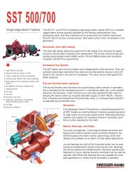
6<br />
First Field Test Installation On Gulf<br />
Of Mexico Deepwater Platform<br />
For Multiphase Turbine Technology<br />
Link <strong>Dresser</strong>-<strong>Rand</strong>’s durable<br />
and reliable machinery design<br />
and manufacturing capabilities<br />
with Kvaerner Process<br />
Systems’ unparalleled<br />
expertise in separation<br />
technology and what do you<br />
get? A unique multiphase<br />
turbine that separates gases<br />
and liquids and generates<br />
power from energy previously<br />
wasted in oil and gas<br />
production.<br />
Multiphase Power &<br />
Processing Technologies LLC<br />
(MPPT), formed in 1998, is a<br />
joint venture between<br />
Kvaerner Process Systems<br />
and <strong>Dresser</strong>-<strong>Rand</strong> Company.<br />
MPPT was created to<br />
develop and market proprietary<br />
multiphase turbines that<br />
separate gas and liquids,<br />
while generating power from<br />
pressure let-down operations.<br />
The biggest market is the<br />
offshore oil and gas industry.<br />
Offshore platforms possess<br />
the unique combination of<br />
high operating pressures,<br />
multiphase (gas, oil, and<br />
water) flow, and minimal<br />
operating space.<br />
MPPT’s equipment is smaller<br />
than conventional systems,<br />
and is based on biphase<br />
turbine technology, acquired<br />
from Douglas Energy<br />
Company of Placentia,<br />
California. Douglas Energy<br />
works with <strong>Dresser</strong>-<strong>Rand</strong> and<br />
Kvaerner as a consultant in<br />
the development and<br />
demonstration of the multiphase<br />
turbine technology.<br />
This equipment is designed to<br />
enable oil and gas producers<br />
to reduce the size of their<br />
production platforms and<br />
subsea modules, and to<br />
generate power needed for<br />
production, with no greenhouse<br />
emissions. This<br />
creates significant footprint,<br />
weight, and total installation<br />
cost savings.<br />
Turbine separators use high<br />
centrifugal forces (up to 5,000<br />
times the force of gravity)<br />
created by pressure letdown<br />
and a rotating drum to rapidly<br />
expel gas from liquid.<br />
Pressure letdown occurs in<br />
nozzles specially designed for<br />
two-phase flow expansion.<br />
Expansion energy of the gas<br />
flashing out of the solution is<br />
effectively transferred to a high<br />
velocity gas-liquid jet mixture<br />
that is used to spin a drum<br />
connected to an output shaft.<br />
The high centrifugal forces<br />
from the rotating drum and<br />
fluid result in effective separation<br />
of gas and liquid within<br />
two to three seconds – as<br />
opposed to 20 minutes in<br />
conventional gravity vessel<br />
separators. This enables<br />
more efficient compact<br />
separation, with lower fluid<br />
inventory (volume).<br />
Originally, the turbine<br />
separator was developed to<br />
separate water and steam<br />
and increase the total energy<br />
produced at a steam turbine<br />
facility in a geothermal<br />
application. The transfer<br />
of this technology from<br />
geothermal to offshore oil and<br />
gas was undertaken to meet<br />
the demanding needs for<br />
deepwater hydrocarbon<br />
production.<br />
An important milestone will<br />
be realized for MPPT this<br />
summer, with the installation<br />
of a full scale Two-Phase<br />
Rotary Separator Turbine<br />
(RST) on an offshore oil<br />
production platform. MPPT<br />
will install this Two-Phase RST<br />
skid package onto the Shelloperated<br />
Ram/Powell tension<br />
leg platform. This platform,<br />
submersed in more than<br />
3,200 feet of water in Viosca<br />
Knoll Block 956, is 125 miles<br />
southeast of New Orleans in<br />
the Gulf of Mexico.<br />
The Ram/Powell field test<br />
marks the turbine’s first<br />
installation into a live<br />
producing facility. “The future<br />
path of MPPT relies on the<br />
test at the Ram Powell<br />
platform,” said Hank Rawlins,<br />
project engineer for MPPT.<br />
The package will be field<br />
tested for three months.<br />
Design conditions are a liquid<br />
flow rate of 20,000 barrels of<br />
oil per day (BOPD) and a gas<br />
flow rate of 30 million standard<br />
ft 3 of gas per day (MMSCFD)<br />
at an inlet pressure of 1,250<br />
psig. Estimated power output<br />
will be 200 kilowatts at full<br />
flow conditions.<br />
During actual well flow<br />
conditions, the turbine will be<br />
required to handle fluctuating<br />
oil, gas, and water flow rates.<br />
Other constituents that may<br />
be present in the well fluids<br />
are produced solids (sand),<br />
scale, foam, wax,<br />
asphaltenes, and hydrates.<br />
Each of these conditions have<br />
been factored into the design<br />
of the turbine.<br />
The skid was built in the<br />
Kvaerner Process Systems<br />
shop in Perth, Australia.<br />
It is a self-contained, selfoperating<br />
skid complete with<br />
control, operating, monitoring,<br />
and testing equipment all<br />
wrapped into one package.<br />
The skid package is 20 ft.<br />
long, eight ft. wide and 10 ft.<br />
tall, and weighs 19 tons. It is<br />
designed to require minimal<br />
operator intervention, and has<br />
the capability of remote<br />
monitoring of turbine performance<br />
from <strong>Dresser</strong>-<strong>Rand</strong>’s<br />
Wellsville, New York, facility.<br />
The turbine that was<br />
developed for this package<br />
was originally tested at the<br />
Texaco-Humble flow test<br />
facility in 1997, and is suitable<br />
for operation with live oil and<br />
gas wells. Extensive factory<br />
testing was further performed<br />
at <strong>Dresser</strong>-<strong>Rand</strong>’s Wellsville<br />
facility, on the hydraulic, safety,<br />
operating, and control<br />
systems to ensure full<br />
mechanical reliability upon<br />
package commissioning in an<br />
offshore environment.<br />
<strong>Dresser</strong>-<strong>Rand</strong> was in charge<br />
of package, integration,<br />
assembly, and factory testing<br />
of the RST. The skid and the<br />
turbine were shipped to the<br />
<strong>Dresser</strong>-<strong>Rand</strong> facility in<br />
Wellsville in early spring for<br />
completion. Package<br />
integration involved installing<br />
the turbine into the package<br />
and finishing the piping,<br />
instrumentation, and control<br />
systems.<br />
“The purpose of the threemonth<br />
test is to show that the<br />
RST can efficiently separate oil<br />
and gas, and that we meet<br />
the predicted power output<br />
with full mechanical reliability,”<br />
stated Rawlins. ■<br />
7
Could your bid evaluations use<br />
a little wait reduction?<br />
WE GIVE YOU ANSWERS IN HOURS, NOT WEEKS.<br />
Now you can get custom energy conversion solutions in record<br />
time, without even doing an RFQ. Our new Product Configurator<br />
Software makes it possible. Its flexible design lets us work<br />
directly with your engineers to quickly and easily analyze<br />
various equipment scenarios. Then it generates complete<br />
specs, drawings and a bill of materials, so you’ll know exactly what you’re getting<br />
and what it will cost. We’ve streamlined the rest of our production process as<br />
well, cutting cycle times by months. To learn how you can save time and money<br />
while getting your new equipment on-line—and generating revenue—faster than<br />
ever before, give us a call. We’ll show you how we can lighten your load.<br />
North and<br />
Latin America:<br />
Tel: (713) 467-2221<br />
Fax: (713) 935-3490<br />
Europe, Middle East,<br />
Eurasia and North Africa:<br />
Tel: 33-235-25-5225<br />
Fax: 33-235-25-5367<br />
Asia-Pacific:<br />
Tel: 60-3-253-6633<br />
Fax: 60-3-253-2622<br />
E-mail: ad@dresser-rand.com<br />
©2000 <strong>Dresser</strong>-<strong>Rand</strong> Company<br />
Expanded Scope Solutions Offer<br />
Single Source For <strong>Dresser</strong>-<strong>Rand</strong><br />
Control Systems Clients<br />
In order to maintain a competitive<br />
edge, companies are<br />
continuously changing their<br />
business practices to remain<br />
up-to-date with current marketplace<br />
requirements, new<br />
technologies, and shareholder<br />
demands.<br />
In the past, clients would<br />
coordinate with several different<br />
suppliers to bring together the<br />
products and services that<br />
made up an entire project.<br />
Today this practice is obsolete.<br />
Companies are now focusing<br />
on single suppliers that can<br />
effectively provide the same<br />
products and services as<br />
several vendors had in the<br />
past in order to reduce<br />
procurement, management,<br />
installation, and start-up costs.<br />
With control system technology<br />
changing at such a rapid pace,<br />
what was state-of-the-art 10<br />
years ago may not be suitable<br />
for today’s monitoring and<br />
control requirements. In<br />
addition to producing the most<br />
advanced machinery control<br />
systems, <strong>Dresser</strong>-<strong>Rand</strong> has<br />
provided expanded scope<br />
solutions for more than<br />
40 years. These capabilities<br />
include site studies to determine<br />
the condition of equipment,<br />
retrofit replacement planning,<br />
engineering, training, project<br />
management, and equipment<br />
removal and installation.<br />
Past projects include supplying<br />
complete onshore and offshore<br />
control systems and auxiliaries<br />
for the compression of gas for<br />
process plants, oil recovery<br />
applications, and many other<br />
services. <strong>Dresser</strong>-<strong>Rand</strong> has<br />
also done complete retrofits of<br />
plant control and auxiliary<br />
systems.<br />
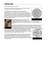
Control Building Project<br />
Expanded scope solutions vary,<br />
but one typical example<br />
demonstrates a retrofit project<br />
that <strong>Dresser</strong>-<strong>Rand</strong> completed<br />
on control and auxiliary<br />
systems for eight <strong>Dresser</strong>-<strong>Rand</strong><br />
25,000 hp offshore compression<br />
modules on two offshore<br />
platforms in Latin America.<br />
The control and electrical<br />
equipment had been in<br />
operation for more than<br />
18 years. Many of the<br />
replacement components were<br />
obsolete and no longer<br />
available, so the client was<br />
experiencing problems with the<br />
availability and reliability of the<br />
compression modules. The<br />
client needed a solution to this<br />
problem and with the help of<br />
<strong>Dresser</strong>-<strong>Rand</strong>, chose to retrofit<br />
the entire system.<br />
The solution involved the<br />
replacement of the control<br />
buildings, including HVAC and<br />
building pressurization equipment.<br />
<strong>Dresser</strong>-<strong>Rand</strong> replaced<br />
the motor control centers,<br />
generator control panels,<br />
automatic transfer switches,<br />
battery systems and chargers,<br />
inverters, gas turbine driven<br />
compression train control<br />
panels, gas turbine fuel valve<br />
and controls, fire detection and<br />
suppression systems, and gas<br />
detection systems. To reduce<br />
downtime for the client, the<br />
buildings were constructed<br />
and completely tested on shore<br />
before being placed on the<br />
platform as a complete<br />
assembly.<br />
<strong>Dresser</strong>-<strong>Rand</strong> completed the<br />
installation and interconnection<br />
of the new control buildings and<br />
finished up the project by<br />
putting the client’s new<br />
equipment on line.<br />
Turnkey Project<br />
On another platform – this one<br />
off the coast of Nigeria –<br />
<strong>Dresser</strong>-<strong>Rand</strong> performed a<br />
complete retrofit of controls for<br />
a compression system with<br />
three gas turbine drivers.<br />
This turnkey project required<br />
engineering expertise to<br />
determine how to integrate the<br />
new control panels into the<br />
client’s existing facility and<br />
operation buildings, remove the<br />
old control systems and install<br />
the new ones, and start-up the<br />
new system.<br />
The control system’s availability<br />
and reliability were increased by<br />
using redundant (hot standby)<br />
control system processors,<br />
which allow for maintenance<br />
and repair while the equipment<br />
is running. Removal of the old<br />
systems, installation of the new<br />
systems, and commissioning<br />
were executed in just 22 days.<br />
As more businesses seek<br />
total solutions from partnervendors<br />
for complete project<br />
management, <strong>Dresser</strong>-<strong>Rand</strong>’s<br />
expanded scope capabilities<br />
become increasingly valuable<br />
to clients, and integral to their<br />
long-term facilities management<br />
plans. ■<br />
8<br />
www.dresser-rand.com/go/innovation Compressors Concept Engineering<br />
Contract/Rental Compression Control Systems Expanders Field Repairs<br />
Gas & Steam Turbines Operation & Maintenance Process Audits Upgrades<br />
By offering expanded scope<br />
solutions and upgrades for<br />
compression and associated<br />
ancillary equipment, <strong>Dresser</strong>-<br />
<strong>Rand</strong> has uniquely positioned<br />
itself to provide total solutions<br />
to the oil, chemical, gas,<br />
and petrochemical industries<br />
through its innovative products<br />
and services.<br />
9
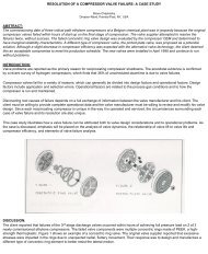
For nine years a prototype<br />
compressed air energy storage<br />
(CAES) plant in McIntosh,<br />
Alabama, has been producing<br />
up to 110 megawatts of<br />
electrical power within 14<br />
minutes of start-up during<br />
periods of high-peak demand.<br />
For nine years the concept has<br />
been proving itself over and<br />
over again, just waiting for the<br />
right market alignment.<br />
And that time is now.<br />
“It’s what our nationwide grid<br />
needs,” says Lee Davis, who<br />
has been manager at the<br />
McIntosh plant since the latter<br />
part of the CAES plant’s<br />
construction. “The electric<br />
industry ought to be excited,<br />
especially as the industry<br />
deregulates.”<br />
The McIntosh plant went on-line<br />
in May, 1991 for the Alabama<br />
10<br />
Compressed Air Energy Storage:<br />
A Technology Whose Time Has Arrived<br />
1.<br />
LEGEND<br />
1. High-pressure compressor<br />
2. Intermediate-pressure<br />
compressor<br />
3. Speed-increasing gear<br />
4. Turning gear<br />
5. Low-pressure compressor<br />
6. Clutch<br />
7. Motor/generator<br />
8. Clutch<br />
9. Low-pressure expander<br />
10. Low-pressure combustors<br />
11. High-pressure expander<br />
12. High-pressure combustors<br />
13. Turning gear<br />
14. Air throttle valve<br />
15. Air trip valve<br />
Electric Cooperative (AEC).<br />
AEC is a generation and<br />
transmission cooperative that<br />
serves member distribution<br />
cooperatives and municipalities<br />
in south central Alabama and<br />
most of the Florida Panhandle.<br />
Since 1991, construction of<br />
new electric generating plants<br />
has come to a standstill<br />
throughout most of the United<br />
States. “That’s why the grid is<br />
in such danger right now,”<br />
Davis says. He cited outages in<br />
Chicago last summer as a<br />
prime example of not having<br />
enough power at the right time<br />
in the right place. Davis thinks<br />
CAES plants are the solution.<br />
It works this way: during low<br />
electric usage periods in the<br />
night (off-peak periods) the AEC<br />
CAES plant compresses and<br />
stores air in an underground salt<br />
2.<br />
3.<br />
4.<br />
cavern. When electric power<br />
demand peaks during the day,<br />
the process is reversed. The<br />
compressed air is returned to<br />
the surface, heated by natural<br />
gas in combustors, and run<br />
through high-pressure and lowpressure<br />
expanders to power<br />
the motor/generator to produce<br />
electricity. It takes less than 15<br />
minutes to bring electric<br />
generation up to capacity.<br />
Using electrical energy to<br />
compress air during off-peak<br />
hours when the cost of<br />
electricity is at its lowest allows<br />
the utility to generate electricity<br />
from the CAES-stored air and<br />
sell it during peak periods. It<br />
uses its CAES plant to boost its<br />
power capabilities during peak<br />
daytime periods when demand<br />
for electric energy skyrockets.<br />
“We buy cheap and displace<br />
high-priced power to our<br />
cooperatives,” Davis explains.<br />
“Basically, I’m very much for the<br />
CAES concept,” Davis says.<br />
“Our load is primarily residential<br />
and CAES fits well with our load<br />
shape. We have a coal-fired<br />
plant 20 miles up the road.<br />
Excess electricity generated by<br />
the coal-fired plant during offpeak<br />
hours is used in McIntosh<br />
to compress air for storage.<br />
5.<br />
“Normal startup for us is 14<br />
minutes to 110 megawatts,” he<br />
says. “I can run down to 10<br />
megawatts. It’s a better<br />
regulating tool.” Control of the<br />
plant for power generation and<br />
compression requirements is<br />
accomplished via microwave<br />
signal by the dispatcher 120<br />
miles away from AEC’s<br />
corporate complex in<br />
Andalusia, Alabama.<br />
In addition, the equipment has<br />
“black start” capability. “Let’s<br />
say you have a blackout. You<br />
can start this equipment without<br />
any outside power,” says Ivan<br />
R. Lehman, product manager<br />
for <strong>Dresser</strong>-<strong>Rand</strong> Company in<br />
Wellsville, New York.<br />
Integral to the McIntosh CAES<br />
plant is <strong>Dresser</strong>-<strong>Rand</strong>, which built<br />
most of the machinery for the<br />
system. The company’s Olean,<br />
New York, operations manufactured<br />
the turbocompressors;<br />
Wellsville operations produced<br />
the gas turbine expanders and<br />
developed the controls; Painted<br />
Post, New York, operations<br />
manufactured the fuel gas<br />
compressors.<br />
“It’s one of the longest trains of<br />
equipment in the world,”<br />
Lehman says. The 140-foot<br />
train has a centrally located<br />
motor/generator with clutches<br />
at each end. On the motor<br />
side, a low-pressure<br />
compressor, intermediate<br />
compressor, and high-pressure<br />
compressor work to compress<br />
the air into the salt dome up to<br />
1,200 psig. Compressor<br />
intercoolers are used at each<br />
6.<br />
of the three compression<br />
stages to maintain equipment<br />
efficiency.<br />
And the equipment has come<br />
to meet expectations in<br />
McIntosh. “After undergoing a<br />
few design modifications, the<br />
<strong>Dresser</strong>-<strong>Rand</strong> equipment is<br />
now performing excellently for<br />
us,” Davis says of the CAES<br />
plant he manages.<br />
The equipment is from <strong>Dresser</strong>-<br />
<strong>Rand</strong>’s various product lines<br />
that have been time- and fieldtested<br />
for decades in various<br />
other applications. The product<br />
7.<br />
140'<br />
line includes single stage<br />
turbines, standard multistage<br />
turbines, packaged geared<br />
turbine generators and engineered<br />
turbine generators,<br />
centrifugal and axial compressors,<br />
gas turbines, and<br />
reciprocating compressors.<br />
Single stage turbines operate up<br />
to 2,500 kilowatts, and the<br />
standard multistage turbines<br />
operate up to 5,000 kilowatts.<br />
Engineered power generation<br />
units are up to 110 megawatts<br />
plus, with an inlet pressure up to<br />
2,000 psig and an inlet temperature<br />
up to 1,000° F (540° C).<br />
8.<br />
9.<br />
Turbine speeds are 2,500 to<br />
20,000 rpm and generate<br />
speeds for 50 cycle or 60 cycle<br />
applications. Packaged turbine<br />
generators come with three<br />
condensing packages and two<br />
back-pressure packages.<br />
AEC used an existing underground<br />
salt dome for<br />
compressed air storage. “We<br />
solution-mined it for 629 days,”<br />
Davis recalls. That created the<br />
space for 19 million cubic feet of<br />
compressed air. For the solution<br />
mining, fresh water was<br />
pumped in to dissolve the salt.<br />
10.<br />
11.<br />
The solution was pumped out to<br />
a nearby chemical manufacturer<br />
that uses brine in its processing.<br />
<strong>Dresser</strong>-<strong>Rand</strong>’s Broken Arrow<br />
facility supplied the portable<br />
compressors that provided the<br />
initial charge for the solutionmined<br />
cavern.<br />
The McIntosh plant uses<br />
existing salt domes, but hard<br />
rock caverns and aquifers can<br />
also be employed. “<strong>Dresser</strong>-<br />
<strong>Rand</strong> is negotiating with a<br />
prospective client with an aquifer<br />
that has a capacity in excess of<br />
230 million cubic feet, compared<br />
to McIntosh's salt cavern of<br />
19 million cubic feet,” says<br />
David Hargreaves, <strong>Dresser</strong>-<br />
<strong>Rand</strong>’s director of business<br />
development.<br />
While the CAES plant has<br />
performed reliably and met<br />
AEC’s needs and requirements<br />
for the last nine years, the<br />
concept otherwise has sat idle<br />
throughout the world since its<br />
beginning. The time is now ripe<br />
for CAES units to become key<br />
components of utilities and<br />
independent power producers.<br />
“We’re involved in several<br />
projects, in the development<br />
stage of issuing proposals,”<br />
Lehman says. And the<br />
company is fielding inquiries<br />
12.<br />
Continued on page 12<br />
13.<br />
14.<br />
11<br />
15.
SPEED RPM<br />
Compressed Air Energy<br />
Storage: A Technology<br />
Whose Time Has Arrived<br />
Continued from page 11<br />
from all parts of the world,<br />
including projects in the United<br />
States, Middle East, Far East,<br />
and Asia.<br />
“There has been a growing<br />
power need around the world,”<br />
Lehman explains. “Utilities have<br />
traditionally met their requirements<br />
for large blocks of power<br />
during peak periods by adding<br />
gas turbine/generators. But the<br />
climbing cost of natural gas and<br />
new emission regulations,<br />
coupled with the long leadtimes<br />
for gas turbines are now<br />
forcing them to rethink their load<br />
management tactics.”<br />
Or, as Davis, the manager of<br />
the McIntosh plant put it, “The<br />
gas turbines had been so<br />
cheap.” But times have<br />
changed over the last nine<br />
years. “Gas turbines are now<br />
very expensive, and right now<br />
because of high demand for<br />
them, you can’t even buy a gas<br />
turbine.”<br />
Gas/turbine generators also<br />
face another problem,<br />
according to Hargreaves.<br />
Output decreases as altitude<br />
START-UP FOR POWER GENERATION<br />
GENERATION<br />
360<br />
3000<br />
240<br />
1800<br />
1200<br />
600<br />
12<br />
0<br />
1<br />
SPE<br />
POWER<br />
EMERGENCY<br />
START<br />
POWER<br />
NORMAL<br />
START<br />
2 3 4 5 6 7 8 9 10 11 12 13<br />
TIME IN MINUTES<br />
and ambient temperatures rise.<br />
“A simple-cycle gas turbine will<br />
put out 85 megawatts at ISO<br />
conditions,” Hargreaves<br />
explains. “The heat rate is<br />
10,500 BTUs per kilowatt hour,<br />
which comes to a cost of<br />
three-plus cents a kilowatt hour.<br />
When the temperature goes up<br />
outside, the turbine loses<br />
capacity. Air that goes into the<br />
front of the turbine becomes<br />
less dense. At 95 degrees the<br />
gas turbine is providing 74<br />
megawatts, and it begins to<br />
take more energy to compress<br />
air. The CAES unit will produce<br />
its rated power in all ambients.”<br />
A CAES unit, on the other<br />
hand, uses less energy. “The<br />
compressor system we use is<br />
intercooled,” Hargreaves says.<br />
“It takes 10 to 15 percent less<br />
power and uses nighttime offpeak<br />
electricity to do<br />
compression. In essence,<br />
CAES is a battery.” He<br />
estimates that CAES-generated<br />
power is produced at a cost of<br />
two cents per kilowatt hour.<br />
CAES equipment is engineered<br />
in modular trains capable of<br />
producing 100 to 135<br />
megawatts of power. As few<br />
as two modules upwards to<br />
more than 15 modules are<br />
being considered per location<br />
to meet future expected local<br />
110<br />
100<br />
90<br />
80<br />
70<br />
60<br />
50<br />
40<br />
30<br />
20<br />
10<br />
POWER MW<br />
demands. CAES is uniquely<br />
qualified to provide reliable<br />
power on a flexible basis to<br />
meet all power requirements<br />
from “intermediate and peak”<br />
demand, including spinning<br />
reserve and standby. <strong>Dresser</strong>-<br />
<strong>Rand</strong> is currently discussing<br />
four-module CAES plants with<br />
START-UP FOR COMPRESSION MODE<br />
360<br />
3000<br />
240<br />
1800<br />
1200<br />
600<br />
SPEE<br />
This Alabama CAES facility, built by <strong>Dresser</strong>-<strong>Rand</strong>, has been<br />
performing reliably since 1991.<br />
0 1 2 3 4 5 6 7 8 9 10<br />
TIME IN MINUTES<br />
110<br />
100<br />
90<br />
80<br />
70<br />
60<br />
50<br />
40<br />
30<br />
20<br />
10<br />
POWER MW<br />
SPEED RPM START-UP FOR COMPRESSION MODE<br />
EXPANDER<br />
POWER<br />
MOTOR<br />
POWER<br />
independent power producers<br />
as merchant plants. “That’s<br />
enough to produce over 500<br />
megawatts of power at one<br />
site,” Hargreaves says.<br />
“Merchant plants merchandise<br />
electricity for anyone who needs<br />
it,” Hargreaves explains. “It’s<br />
like the spot gas market.” It’s<br />
an offshoot of the continuing<br />
deregulation of the utility<br />
industry.<br />
<strong>Dresser</strong>-<strong>Rand</strong> is sitting in the<br />
driver’s seat for future CAES<br />
plants. It is the only company<br />
with an enviable track record,<br />
meeting the peak load periods<br />
of the AEC on a daily basis.<br />
Clearly, storing excess electricity<br />
generated during low peak<br />
periods is the ideal answer.<br />
And CAES has proven for the<br />
past nine years to perform with<br />
unmatched reliability. ■<br />
Distant Equipment Monitoring At Your<br />
Fingertips; Models, Active Simulation<br />
Available On-Line<br />
Instant situation diagnosis and<br />
long-term equipment health<br />
analysis are now at the<br />
fingertips of <strong>Dresser</strong>-<strong>Rand</strong><br />
clients anywhere in the world<br />
who have signed on for remote<br />
monitoring and control for the<br />
operation of rotating equipment<br />
systems.<br />
With remote monitoring through<br />
its Global Access MC<br />
system, available since January<br />
2000, <strong>Dresser</strong>-<strong>Rand</strong> clients are<br />
now making use of this system<br />
that allows them to monitor<br />
equipment and controls<br />
performance from anywhere,<br />
said Tim Walker, Marketing<br />
Engineer for <strong>Dresser</strong>-<strong>Rand</strong><br />
Control Systems in Houston.<br />
Remote monitoring is available<br />
through <strong>Dresser</strong>-<strong>Rand</strong>’s Global<br />
Access MC system via Internet,<br />
direct phone line, or by satellite<br />
link. Other than a personal<br />
computer, no special equipment<br />
is necessary. “If they have a<br />
computer and a net browser,<br />
they don’t need any other<br />
equipment,” Walker said.<br />
Clients interested in the system<br />
can log onto a static demonstration<br />
model on the<br />
company's web site at dresserrand.com<br />
and the Global<br />
Access MC demonstration link<br />
on the Controls page and<br />
navigate through the fixed<br />
model.<br />
The model contains areas for<br />
comments and for requests<br />
for additional information.<br />
A <strong>Dresser</strong>-<strong>Rand</strong> representative<br />
will contact the user and<br />
provide a password for access<br />
to the company's active<br />
dynamic system on simulation<br />
at the Control Systems’ product<br />
development laboratory in<br />
Houston, Walker said.<br />
Remote monitoring holds vast<br />
potential for both clients and<br />
<strong>Dresser</strong>-<strong>Rand</strong>, Walker said.<br />
“It facilitates the monitoring of<br />
clients’ equipment. We’re<br />
looking at reducing or eliminating<br />
on-site service personnel,<br />
which will very likely have a<br />
major, favorable impact on cost<br />
and the feasibility of long-term<br />
service agreements.”<br />
Remote monitoring provides<br />
immediate turn-around for<br />
solving problems. “Historically,<br />
the client and <strong>Dresser</strong>-<strong>Rand</strong><br />
would go to quite a bit of<br />
expense and time to even<br />
evaluate a problem. With<br />
Global Access MC, that difficulty<br />
is eliminated. We can evaluate<br />
the situation before a technician<br />
gets on a plane. Equipment<br />
and control engineers can<br />
examine the data in counsel<br />
with the client’s staff experts.<br />
“We can see some things, and<br />
log some events. We’re all<br />
looking at the same data and<br />
making a determination whether<br />
maintenance or replacement is<br />
required. We can determine<br />
whether we need a mechanic<br />
or a control system technician.”<br />
The remote monitoring system<br />
allows <strong>Dresser</strong>-<strong>Rand</strong> to expand<br />
its Asset Management business<br />
by offering better, faster service<br />
for clients’ heavy capital<br />
equipment. It also gives<br />
<strong>Dresser</strong>-<strong>Rand</strong> the timely<br />
informational wherewithal<br />
to provide more accurate<br />
projections of equipment health<br />
and maintenance schedules.<br />
Benefits to the user are<br />
immediate. The continuous<br />
acquisition of data through<br />
<strong>Dresser</strong>-<strong>Rand</strong>’s Global Access<br />
MC system provides equipment<br />
operators with access to<br />
temperature and vibration<br />
displays, comprehensive analog<br />
summaries and status lists,<br />
surge control displays, current<br />
and historical alarms, and<br />
current and historical trends of<br />
all analog signals.<br />
The Global Access MC<br />
server on the control<br />
system includes<br />
Windows NT ® with remote<br />
access enabled, web server<br />
software, and a 56k modem.<br />
The remote PC requires<br />
Windows 95/98 or NT ® ,<br />
Netscape Navigator ® 4.07 or<br />
higher, or Microsoft Explorer ®<br />
4.01 or higher, and a 56k<br />
modem. Connection between<br />
the server and the remote PC<br />
can be by phone line, Internet,<br />
or satellite.<br />
“There are ways to provide<br />
security through dedicated<br />
phone line or local area<br />
network,” Walker said.<br />
“Offshore platforms and remote<br />
sites have satellite links and<br />
microwave repeaters.”<br />
From offshore platforms, to<br />
pipelines, to processing plants<br />
— all are candidates for remote<br />
monitoring and control through<br />
Global Access MC. ■<br />
13
Performance Evaluation<br />
And Fluid Flow Analysis In<br />
Low Flow Stages Of<br />
Industrial Centrifugal<br />
Compressor<br />
by Yuri I. Biba, David A. Nye<br />
and Zheji Liu <strong>Dresser</strong>-<strong>Rand</strong><br />
Company, Olean, New York<br />
Editors Note: This paper<br />
was presented at the 8th<br />
International Symposium of<br />
Transport Phenomena and<br />
Dynamics of Rotating<br />
Machinary (ISROMAC-8),<br />
6-30 March 2000.<br />
Abstract<br />
A comparative study of the flow<br />
field and performance of<br />
centrifugal compressor stages<br />
is presented for low volume<br />
flows and high-pressure<br />
applications. Two different<br />
impeller designs and stage<br />
configurations are considered<br />
and modeled using commercial<br />
Computational Fluid Dynamics<br />
(CFD) codes. Internal stage<br />
designs are evaluated by<br />
qualitative and quantitative flow<br />
analysis with the goal being to<br />
obtain more efficient stages.<br />
The resulting improved<br />
configurations are implemented<br />
into one of <strong>Dresser</strong>-<strong>Rand</strong>’s<br />
compressors. Computational<br />
and experimental results are<br />
discussed and conclusions are<br />
made regarding the existing<br />
model, as well as future<br />
improvements, both in<br />
modeling and design concepts.<br />
Nomenclature<br />
D 2 – overall impeller diameter<br />
D 5 – diffuser outlet diameter<br />
Q 0 – volumetric flow at stage<br />
inlet<br />
u 2 – impeller speed at overall<br />
diameter<br />
� – low coefficient,<br />
�=4Q 0 /(�u 2 D 2 2 )<br />
� - polytropic efficiency<br />
� - polytropic head coefficient<br />
Introduction<br />
Centrifugal compressor<br />
impellers for low flow coefficients<br />
� are subjects of specific<br />
interest due to their application<br />
in process industry and gas<br />
Figure 1. Cross Section of Last Three Stages of a High-Pressure<br />
Centrifugal Compressor.<br />
14<br />
injection markets. In these<br />
applications such impellers are<br />
often used in the last stages at<br />
high-pressure levels.<br />
A systematic study of low flow<br />
compressor stages has been<br />
presented by Casey et al.,1990.<br />
It is noticed that a simple<br />
dissipation loss model was<br />
unable to predict, with any<br />
certainty, which of the impellers<br />
of different design would have<br />
the best performance.<br />
Extensive experimental studies<br />
for all impellers are necessary to<br />
identify the most efficient one.<br />
Impeller maximum efficiency<br />
drops rapidly with the decrease<br />
of design volume flow (Balje,<br />
1981) making it very difficult to<br />
improve stage efficiency for<br />
lower flow values. That general<br />
trend has not changed with<br />
years of extensive development<br />
efforts by major turbomachinery<br />
manufacturers (Dalbert et al.,<br />
1999). <strong>Dresser</strong>-<strong>Rand</strong> has been<br />
using CFD to design new, more<br />
efficient, families of low flow<br />
impellers to apply in the last<br />
stages of high-pressure<br />
compressors.<br />
Figure 2. Stage Performance at Various � and D 5 /D 2<br />
Calculated by STGPERF.<br />
Recent progress in CFD code<br />
development and decreased<br />
computing cost make more<br />
detailed computational analysis<br />
possible. At the same time,<br />
experimental testing remains<br />
very expensive and will likely<br />
need to be reduced. CFD<br />
modeling or a Virtual Test Rig<br />
(VTR) approach is routinely<br />
used, while experimental testing<br />
remains a final verification tool.<br />
<strong>Dresser</strong>-<strong>Rand</strong> has implemented<br />
the VTR concept since the<br />
company began its use of<br />
CFD software. CFD has been<br />
routinely used to compare<br />
analytical predictions with test<br />
results to augment test data and<br />
validate predictions (Sorokes<br />
and Koch,1996).<br />
Many issues need to be<br />
addressed before a sufficient<br />
level of confidence is gained to<br />
assess performance change via<br />
CFD studies. Part of this<br />
responsibility is certainly part of<br />
the VTR study, where the effects<br />
of grid density, windage, leakage,<br />
surface roughness, frame size,<br />
etc. will need to be addressed.<br />
However, full confidence can<br />
really only be gained through<br />
calibration and comparison with<br />
test data. This test data can<br />
originate from extended scope<br />
instrumentation on production<br />
rigs or improved Single Stage<br />
Test Rig (SSTR) testing. While<br />
the VTR is being developed, the<br />
new stages can be optimized<br />
Figure 3. Typical CFD Grid Arrangement.<br />
using CFD to assess additional<br />
design improvements.<br />
Background<br />
It was decided to implement<br />
a new design for the last three<br />
stages of a multistage highpressure<br />
barrel compressor.<br />
Flow coefficients � for these<br />
stages are 0.0146, 0.0117 and<br />
0.0097, respectively. These<br />
three stages (Figure 1) were<br />
selected to replace original<br />
impellers that are characterized<br />
by relatively small backsweep<br />
and narrow flow passages.<br />
The existing designs are replaced<br />
by the new impellers with wider<br />
passages and a significantly<br />
larger blade backsweep angle.<br />
The intent of the design was to<br />
reduce flow velocity and loading<br />
throughout the stage, make the<br />
impeller exit flow more uniform to<br />
reduce stage losses, and<br />
produce slightly less head than<br />
the original design.<br />
Preparatory study was<br />
performed to determine the<br />
optimum diffuser size. This<br />
study used <strong>Dresser</strong>-<strong>Rand</strong>’s<br />
proprietary semi-empirical, onedimensional<br />
analytical code<br />
STGPERF. A number of cases<br />
were run on STGPERF to<br />
investigate the influence of the<br />
diffuser radius ratio. This ratio<br />
was varied between 1.25 and<br />
1.49 for stages with flow<br />
coefficients from 0.0032 to<br />
0.0275. Efficiency plots are<br />
shown in Figure 2. The results<br />
showed that for a stage<br />
F=0.0275, the peak efficiency<br />
was achieved at the larger<br />
diffuser radius ratio. For the<br />
lowest flow stage, peak<br />
efficiency was achieved at the<br />
lower value of diffuser radius<br />
ratio, with indications that even<br />
lower values of radius ratio may<br />
be beneficial. For a stage � =<br />
0.0069 STGPERF predicts a<br />
neutral influence of diffuser radius<br />
ratio on peak efficiency.<br />
The conclusion drawn from the<br />
investigation is that higher flow<br />
stages require larger radius ratio<br />
vaneless diffusers than smaller<br />
flow stages. The positive<br />
influence of vaned diffuser<br />
systems in lower specific flow<br />
stages does not change that<br />
conclusion; in fact, it may expand<br />
this conclusion. A vaned diffuser<br />
tends to move the stage with<br />
neutral influence of diffuser radius<br />
ratio to a larger � value and also<br />
tends to move the minimum<br />
diffuser ratio to a lower value.<br />
As in the existing design, an<br />
impeller with a flow coefficient<br />
0.0275 is chosen as the parent<br />
impeller of the whole family.<br />
Each impeller with a flow<br />
coefficient less than 0.0275 (but<br />
greater that 0.0077) can be<br />
obtained from the parent impeller<br />
by a proper meridional contour<br />
cut. The parent impeller is<br />
included in the analysis because<br />
it is the only low flow wheel of<br />
existing design that had been<br />
tested in the SSTR until this time.<br />
The main focus of the current<br />
work revolves around past and<br />
present stage configurations in<br />
a CFD study comparing<br />
performance of the original and<br />
new stages. The operating<br />
conditions chosen are for a single<br />
wheel speed under typical SSTR<br />
conditions: inlet pressure 30 psia,<br />
inlet temperature<br />
100° F, and nitrogen as the<br />
working gas. A description of the<br />
SSTR can be found in the work<br />
of Sorokes and Welch,1992.<br />
The stages compared have<br />
significantly different stationary<br />
component configurations, which<br />
are not necessarily optimum.<br />
The two fundamental differences<br />
that should be noted in this<br />
discussion are the shorter radius<br />
ratio used in the new design<br />
versus a larger radius ratio<br />
used as the current standard.<br />
In addition, due to the high<br />
backsweep used in the new<br />
impeller designs Low Solidity<br />
Diffusers (LSD) are required,<br />
whereas the old design is better<br />
served using a vaneless diffuser.<br />
Therefore, the new and old low<br />
flow configurations should be<br />
compared as a stage for any<br />
proposed adjustments to overall<br />
compressor performance.<br />
Continued on page 16<br />
Figure 4. Velocity Field Colored by Mach Number at Design Flow,<br />
� = 0.0275, New Design.<br />
15
Performance Evaluation<br />
And Fluid Flow Analysis In<br />
Low Flow Stages Of.....<br />
Continued from page 15<br />
It must be noted that the<br />
CFD results should only be<br />
compared directly with other<br />
CFD results, since the modeling<br />
does not completely capture all<br />
physical reality (disk friction,<br />
leakage, etc.).<br />
Figure 5. Velocity Field Colored<br />
by Mach Number at Design<br />
Flow, � = 0.0275, Old Design.<br />
CFD Analysis<br />
Obtained flow fields are<br />
analyzed to identify possible<br />
flow separation or other specific<br />
areas of losses (like flow nonuniformity)<br />
that may cause<br />
decreased efficiency or<br />
insufficient head rise.<br />
The stage grid consists of four<br />
parts: vaneless radial inlet region<br />
(not shown), impeller, LSD<br />
including one-half of the return<br />
bend, and return channel with the<br />
remaining portion of the return<br />
bend, as shown in Figure 3.<br />
A commercial CFD code CFX-<br />
Tascflow ® ‚ a product of AEA<br />
Technology Engineering<br />
Software, was used for the<br />
stage analysis. Three “frozen<br />
rotor” interfaces were applied to<br />
attach grid regions; the total<br />
number of nodes is approximately<br />
150,000. One blade<br />
passage was considered for<br />
each component, with<br />
16<br />
circumferentially periodic<br />
boundary conditions. Mass<br />
flow boundary was utilized at<br />
the stage outlet, while averaged<br />
flow angle and stagnation<br />
pressure and temperature were<br />
imposed at the inlet.<br />
For the parent impeller stage<br />
(� = 0.0275) at design flow,<br />
separation is not apparent in the<br />
stationary components or<br />
impeller (Figure 4). Flow velocity<br />
Figure 6. Velocity Field Colored<br />
by Mach Number at 62% of<br />
Design Flow, � = 0.0275,<br />
New Design.<br />
remains relatively high in the<br />
inlet region due to leading edge<br />
incidence effects and blade<br />
thickness blockage. However,<br />
the relative Mach number<br />
increase is not as high as that<br />
observed in the old impeller<br />
(Figure 5). Impeller loading<br />
decreases around trailing edge,<br />
thus minimizing the wake<br />
originating from the suction side<br />
of the blade, and making the<br />
flow field behind the impeller<br />
more uniform. Most of the<br />
head is generated by approximately<br />
60 percent of the blade<br />
in the mid-passage region.<br />
At 78 percent mass flow, no<br />
recirculation zones were found<br />
in the impeller. A low-energy<br />
region, mainly near the shroud<br />
surface, occurred at the suction<br />
side midway through the blade<br />
passage, but the high exit<br />
backsweep does not allow<br />
the wake to spread.<br />
A small local recirculation zone<br />
occurs near the hub at the<br />
trailing edge of the suction side<br />
of the LSD vane, but the wake<br />
is relatively small due to the<br />
higher velocity flow coming from<br />
the pressure side.<br />
At even lower mass flow<br />
(62 percent of design value), a<br />
small separation zone with a<br />
recirculation was found at the<br />
hub-suction corner of the<br />
Figure 7. Velocity Field Colored<br />
by Mach Number at Design<br />
Flow, � = 0.0117, New Design.<br />
impeller blade passage (Figure 6).<br />
High velocities were observed at<br />
the impeller inlet on the suction<br />
side of the blade, resulting from<br />
incidence and flow turning<br />
around the leading edge. In the<br />
mid and exit part of the blade<br />
passage a low-energy zone can<br />
be seen at the suction side, but<br />
without separation.<br />
A local separation zone<br />
occurred at the hub-suction side<br />
of the LSD vane near the trailing<br />
edge that results in a wake flow<br />
region in the return bend<br />
entrance.<br />
At overload (120 percent design<br />
mass flow), impeller flow was<br />
without separation, but flow with<br />
a higher relative Mach number is<br />
found at the inlet, both on the<br />
suction and pressure sides of<br />
the blade. The latter is due to<br />
incidence effects and the<br />
corresponding turning required<br />
around the leading edge. For<br />
this flow case the LSD region<br />
has a strong recirculation zone<br />
on the pressure side of the<br />
blade, and the resulting wake<br />
washes out only in the second<br />
half of the return bend.<br />
For smaller stages (� = 0.0146<br />
and lower), the flow field in the<br />
impeller and diffuser looks similar<br />
to that in the parent stage, both<br />
at design and off-design points.<br />
The separation zone is found in<br />
Figure 8. Static Pressure Field<br />
in the Impeller and LSD At<br />
Design Flow, � = 0.0275,<br />
New Design, Mid-Span.<br />
the LSD region at the low flow<br />
condition on the suction side of<br />
the vane, close to the trailing<br />
edge and shroud surface.<br />
Figure 7 illustrates the flow field<br />
in the newly designed impeller<br />
with a flow coefficient of 0.0117.<br />
Static pressure plot in the<br />
impeller and the LSD mid-span<br />
region is shown in Figure 8.<br />
At low flow, the recirculation<br />
eddy is washed out in the LSD<br />
quickly enough to smooth the<br />
velocity profile in the return<br />
bend. A typical low velocity<br />
zone in the impeller was located<br />
at the outlet on the suction side<br />
of the blade, becoming more<br />
severe toward the shroud<br />
surface. In addition, the wake<br />
entering the diffuser from the<br />
impeller is not very strong.<br />
A CFD model was built to<br />
analyze the flow in the<br />
discharge volute. As shown in<br />
Figure 9, about 400,000 nodes<br />
were used to mesh the return<br />
Figure 9. Volute Grid for CFD Model.<br />
Figure 10. Volute Static Pressure Contour Plot.<br />
Figure 11. Comparison of Normalized Optimum Efficiency and<br />
Head Coefficient at Best Efficiency Point for New and Old Design<br />
Impellers and Stages.<br />
bend, the volute, and the<br />
discharge nozzle. A commercial<br />
code Star-CD ® from<br />
Computational Dynamics Ltd.<br />
was used to run this model.<br />
A mass flow rate boundary<br />
condition was applied to the<br />
inlet, at the entrance to the<br />
return bend. At the exit of the<br />
discharge nozzle, an outflow<br />
boundary condition was applied.<br />
Figure 10 shows the static<br />
pressure distribution computed<br />
by the CFD model. The flow field<br />
in the volute was uniform with no<br />
major loss regions.<br />
Performance Comparison<br />
Figure 11 shows peak efficiency<br />
and polytropic head coefficient<br />
at peak efficiency based on the<br />
CFD results and SSTR. The first<br />
item that should be noted is that<br />
CFD overpredicts the test data<br />
for low flow coefficients, while<br />
underpredicting data at higher<br />
values of flow coefficients. The<br />
underlying causes for these<br />
differences are most likely due to<br />
influences external to the main<br />
flow path which were not<br />
modeled (e.g. friction in the<br />
impeller cavity and leakage),<br />
as well as numerical sources<br />
(e.g. grid dependency), and<br />
turbulence modeling. There are<br />
several other items of interest<br />
that should be noted from<br />
Figure 11. First, the impeller<br />
efficiency curves predicted by<br />
CFD track relatively closely to<br />
one another, although the new<br />
impeller appears to exhibit<br />
slightly lower efficiency in the<br />
lower flow capacity stages.<br />
On a stage basis the new<br />
stages appear to exhibit a near<br />
constant peak efficiency across<br />
the entire flow range. The older<br />
stage peak efficiencies follow<br />
more closely to the empirical<br />
curve.<br />
An alternative presentation of<br />
the peak efficiency and head<br />
coefficient at peak efficiency is<br />
shown in Figure 12. The CFD<br />
data shown on this plot are<br />
normalized by maximum values<br />
of peak efficiency and head<br />
coefficient, while the empirical<br />
data were normalized to agree<br />
with the CFD results for the old<br />
stage with � = 0.0275. These<br />
results demonstrate more clearly<br />
the differences in curve shape<br />
and relative performance of the<br />
stage designs. Clearly, the new<br />
stage shows significant<br />
improvement in performance<br />
when compared to the old<br />
stage. The actual level of<br />
improvement cannot be<br />
determined without further<br />
calibration of the predictions<br />
with empirical data.<br />
Head coefficient � curves<br />
(shown in Figures 11 and 12)<br />
correspond to the peak<br />
efficiency operating points.<br />
The results indicate higher head<br />
levels at peak efficiency for both<br />
the current (“old”) impeller and<br />
stage designs. The results also<br />
imply better pressure recovery in<br />
the stationary components for<br />
the new design, based on the<br />
comparison of � for the impeller<br />
and stage curves.<br />
The general shape of the CFD<br />
predicted curves for � are<br />
relatively flat with a peak in the<br />
0.010 – 0.015 flow coefficient<br />
range, while the empirical curve<br />
and SSTR data suggest an<br />
increasing trend for � with flow<br />
coefficient. The reason for this<br />
discrepancy most likely lies in<br />
the lack of leakage and external<br />
secondary flow path windage<br />
losses; internal flow path<br />
roughness may also be a factor.<br />
In addition, previous comparison<br />
with SSTR data indicates that<br />
the CFD results appear to<br />
underestimate the impeller<br />
slip factor.<br />
Figure13 illustrates individual<br />
stage performance along a<br />
speed line. The new stage with<br />
� = 0.0146 exhibits the typical<br />
curve shape expected with<br />
LSD’s higher peak efficiency<br />
with slightly shorter range.<br />
Continued on page 18<br />
17
Performance Evaluation<br />
And Fluid Flow Analysis In<br />
Low Flow Stages Of.....<br />
Continued from page 17<br />
Relative peak efficiency<br />
adjustments for STGPERF were<br />
suggested based on the CFD<br />
results obtained, assuming that<br />
the difference in head and<br />
efficiency between the new<br />
stage design and the original<br />
design may be identical to the<br />
actual change in performance<br />
of the physical machine.<br />
Comparison With<br />
Production Test<br />
The one-dimensional analysis<br />
code STGPERF was modified<br />
based on the aforementioned<br />
CFD results to ensure performance<br />
prediction for stages<br />
with newly designed low flow<br />
impellers. Based on stageby-stage<br />
calculations, the overall<br />
compressor performance was<br />
predicted at test conditions and<br />
compared with test results.<br />
Intermediate test data were<br />
gathered between stages<br />
where total pressure and<br />
temperature probes were<br />
installed in the return bend area.<br />
Comparison of newly predicted<br />
and tested data for the entire<br />
compressor is shown in Figure<br />
14. The results demonstrate<br />
very good agreement of head<br />
coefficient and relatively good<br />
agreement of efficiency values.<br />
The discrepancy does not<br />
exceed 2.5 percent and is<br />
greater at low flow capacity<br />
conditions.<br />
Conclusions<br />
The proposed new stage<br />
design demonstrated improved<br />
efficiency compared to the<br />
previous design that made new<br />
geometric configuration<br />
successful in a high-pressure<br />
compressor and for similar<br />
applications. It should be noted<br />
that when applying the newly<br />
designed low flow stages,<br />
operating range is reduced due<br />
to utilization of LSD’s. Additional<br />
18<br />
design improvements are<br />
possible, e.g. adjusting impeller<br />
leading edge position and/or<br />
changing the number of blades,<br />
optimizing return channel/bend<br />
geometry, etc.<br />
The efficiency improvement has<br />
been predicted by a series of<br />
CFD calculations at various flow<br />
capacity values and verified<br />
experimentally by testing the<br />
compressor with the newly<br />
designed changes. Qualitative<br />
agreement between computational<br />
and test data has been<br />
obtained. Quantitatively, the<br />
CFD calculations slightly<br />
over-predict the performance.<br />
This discrepancy is caused by<br />
numerous factors not being<br />
taken into account in the<br />
computational model and CFD<br />
tools such as secondary losses<br />
in labyrinth seal passages,<br />
surface roughness, inlet and<br />
intermediate flow non-uniformity,<br />
transient effects, turbulence<br />
modeling, near-wall flow<br />
resolution, etc. Some of these<br />
effects represent a challenge for<br />
CFD methods to predict them<br />
accurately. At its current level of<br />
development CFD cannot be<br />
used for direct performance<br />
predictions. However, CFD is<br />
an excellent tool for providing<br />
data for relative dimensionless<br />
comparison and analysis of<br />
the impact of design and flow<br />
parameters on performance of<br />
centrifugal compressor<br />
components.<br />
For practical reasons, it is<br />
possible to define a set of key<br />
parameters that will allow a<br />
designer to perform a parametric<br />
study of the impact on<br />
stage performance using CFD.<br />
Results of that study, together<br />
with available test data, can be<br />
used to tune the existing<br />
models implemented in a<br />
semi-empirical 1D code (like<br />
<strong>Dresser</strong>-<strong>Rand</strong>’s STGPERF)<br />
to enable it to predict stage<br />
and overall compressor<br />
performance with accuracy.<br />
Ultimately, this parametric<br />
approach will also make the<br />
1D code more generic in nature<br />
(i.e., able to analyze the full<br />
range of stage geometry) as<br />
well as open the doors to its<br />
application as an inverse design<br />
tool that could be used to tailor<br />
stage design to operating<br />
specific conditions.<br />
In current conditions of rising<br />
research and production<br />
test costs, the problem of<br />
calibration of CFD codes for<br />
turbomachinery becomes a<br />
key factor in performance<br />
prediction. Consequently,<br />
<strong>Dresser</strong>-<strong>Rand</strong> continuously<br />
strives to develop its test and<br />
computational programs,<br />
including both SSTR rigs and<br />
expanding CFD capabilities. ■<br />
Figure 12. Comparison of Normalized Optimum Efficiency and<br />
Head Coefficient at Best Efficiency Point for New and Old Design<br />
Stages. Alternative Normalization.<br />
Figure 13. Comparison of CFD-based Performance Curves for<br />
New and Old Stages at � = 0.0146.<br />
Figure 14. Comparison Between Tested and Predicted Overall<br />
Compressor Performance Characteristics.<br />
<strong>Dresser</strong>-<strong>Rand</strong> Expands Service<br />
Capabilities For Reciprocating<br />
Compressors And Integral Gas Engines<br />
<strong>Dresser</strong>-<strong>Rand</strong> has announced<br />
the formation of an expanded<br />
engineered solutions operation<br />
to provide expert analysis and<br />
service for all makes of process<br />
reciprocating compressors and<br />
integral gas engines, including<br />
non-<strong>Dresser</strong>-<strong>Rand</strong> equipment.<br />
The new operation, the Applied<br />
Technology Department,<br />
located in Grove City,<br />
Pennsylvania, is an extension of<br />
<strong>Dresser</strong>-<strong>Rand</strong>’s Engineered<br />
Solutions group based in<br />
Painted Post, New York.<br />
Applied Technology is headed<br />
by George Elefteriou, project<br />
manager, who joined <strong>Dresser</strong>-<br />
<strong>Rand</strong> in March, after more than<br />
25 years experience with<br />
Cooper Energy Services.<br />
Elefteriou brings to <strong>Dresser</strong>-<br />
<strong>Rand</strong> a team of engineers and<br />
technicians with a combined<br />
150 years of experience in field<br />
service and engineering.<br />
The group reports to Fred<br />
Tanneberger, vice president of<br />
Engineered Solutions for<br />
<strong>Dresser</strong>-<strong>Rand</strong> Product Services<br />
in Painted Post.<br />
“Our clients will be able to<br />
upgrade or revamp their<br />
existing equipment – regardless<br />
of make or model – with the<br />
most advanced engineered<br />
components and assemblies,”<br />
Tanneberger said. “We’re not<br />
replicating parts, but instead,<br />
providing the latest technology<br />
and designs for improved<br />
efficiency and reliability of<br />
operation.”<br />
Formation of Applied<br />
Technology is a direct response<br />
to clients’ desire to have one<br />
supplier work on all of their<br />
equipment. It also expands<br />
<strong>Dresser</strong>-<strong>Rand</strong>’s expertise as a<br />
single source supplier to the<br />
industry. During the past 100<br />
years, <strong>Dresser</strong>-<strong>Rand</strong> has<br />
shipped more than 8,000<br />
process reciprocating compressors<br />
and 9,000 integral gas<br />
engines. This vast experience<br />
as an equipment manufacturer,<br />
combined with extensive<br />
experience in field service,<br />
benefits <strong>Dresser</strong>-<strong>Rand</strong>’s clients<br />
by providing advanced<br />
capabilities for technology and<br />
total solutions capabilities,<br />
including:<br />
- Site Audits<br />
- Field Analysis and Problem<br />
Solving<br />
- Equipment Upgrades<br />
- Complete Revamps<br />
- Remanufactured Units<br />
- Field Installation and Service<br />
- Total Solutions<br />
“There are no restrictions on the<br />
makes or models of equipment<br />
that we can service,” says<br />
Elefteriou. “As an OEM, we<br />
understand the challenges of<br />
the equipment. And no other<br />
company has this range of<br />
manufacturing experience<br />
combined with <strong>Dresser</strong>-<strong>Rand</strong>’s<br />
technical support and extensive<br />
field service organization.”<br />
For information on <strong>Dresser</strong>-<br />
<strong>Rand</strong>’s Applied Technology<br />
services for reciprocating<br />
compressors and integral gas<br />
engines, contact a D-R sales<br />
representative; call <strong>Dresser</strong>-<br />
<strong>Rand</strong> at (724) 450-2081;<br />
or send an email to:<br />
george_k_elefteriou@dresser<br />
-rand.com. ■<br />
19
<strong>Dresser</strong>-<strong>Rand</strong> Wins<br />
Contract For Combined<br />
Cycle Power Generation<br />
Arizona Public Service/<br />
Pinnacle West Energy has<br />
awarded <strong>Dresser</strong>-<strong>Rand</strong> a<br />
contract for a 45 megawatt<br />
steam turbine generator set to<br />
be installed in Phoenix, at the<br />
Pinnacle West Energy<br />
combined cycle plant.<br />
The steam turbine generator<br />
set will be delivered in October<br />
2000, with plant start-up<br />
scheduled for June 2001.<br />
<strong>Dresser</strong>-<strong>Rand</strong> will provide onsite<br />
training for APS/Pinnacle<br />
West Energy associates,<br />
installation, and start-up for<br />
the project.<br />
“This project reflects a great<br />
opportunity for <strong>Dresser</strong>-<strong>Rand</strong><br />
to further demonstrate our<br />
ability in the steam turbine<br />
power generation market,”<br />
said Doug Gewand, product<br />
manager for Large Steam<br />
Turbines at <strong>Dresser</strong>-<strong>Rand</strong>.<br />
Alliance With Liburdi<br />
Engineering To Extend Life<br />
Of Power Turbine<br />
Components<br />
<strong>Dresser</strong>-<strong>Rand</strong> and Liburdi<br />
Engineering Limited have<br />
entered into an alliance<br />
agreement to provide<br />
advanced component repair<br />
and rejuvenation services for<br />
<strong>Dresser</strong>-<strong>Rand</strong>’s complete line<br />
of power turbines.<br />
According to company<br />
officials, Liburdi Engineering’s<br />
experience in advanced repair<br />
processes for turbine blades<br />
and vanes, coupled with<br />
<strong>Dresser</strong>-<strong>Rand</strong>’s turbine design<br />
expertise and Power Turbine<br />
Life Extension program, will<br />
permit clients to safely and<br />
economically extend the<br />
operating life of their power<br />
turbines beyond the original<br />
“design” life.<br />
Joe Liburdi, president of Liburdi<br />
Engineering, stated, “This<br />
alliance will allow us to quickly<br />
introduce proven repair<br />
technologies and provide<br />
<strong>Dresser</strong>-<strong>Rand</strong>’s [turbine] users<br />
with the combined benefit of<br />
component life extension and<br />
OEM support.”<br />
Walt Nye, executive vice<br />
president of <strong>Dresser</strong>-<strong>Rand</strong>’s<br />
Product Services organization,<br />
commented, “Liburdi<br />
Engineering’s expertise in<br />
component repair, combined<br />
with our design knowledge,<br />
allows us to economically and<br />
safely develop repair and<br />
rejuvenation processes that<br />
extend the operating life of<br />
power turbine components.<br />
We have the opportunity to offer<br />
our clients a choice between<br />
new and refurbished parts.<br />
“We’re committed to<br />
supporting our products, and<br />
we’ll continue to develop<br />
product upgrades, repair<br />
techniques, and support<br />
services that benefit our<br />
clients.” ■<br />
<strong>Dresser</strong>-<strong>Rand</strong> Forms<br />
Alliance To Improve Air<br />
Quality In China<br />
Engeturb Offers Full<br />
Service For Latin<br />
American Clients<br />
<strong>Dresser</strong>-<strong>Rand</strong> recently<br />
acquired controlling interest in<br />
Engeturb to provide a full line<br />
of products and services for its<br />
Latin American client base.<br />
Engeturb’s steam product line<br />
has remained viable<br />
throughout its ten-year<br />
association with <strong>Dresser</strong>-<br />
<strong>Rand</strong>. The company will<br />
maintain its current steam<br />
turbine product line to serve<br />
the Latin American steam<br />
turbine generator market<br />
under 20 megawatts.<br />
Engeturb’s Campinas facility,<br />
65 miles north of Sao Paulo,<br />
Brazil, brings <strong>Dresser</strong>-<strong>Rand</strong>’s<br />
worldwide total of service<br />
centers to 23, which includes<br />
another Latin American-based<br />
service center in Maracaibo,<br />
Venezuela.<br />
The facility is making a<br />
transition to a fully integrated<br />
<strong>Dresser</strong>-<strong>Rand</strong> service center.<br />
When completed, it will<br />
provide total energy conversion<br />
solutions and services<br />
throughout Latin America<br />
for all reciprocating, centrifugal,<br />
and steam turbine product<br />
lines.<br />
<strong>Dresser</strong>-<strong>Rand</strong> Publishes<br />
Guide To Naval Steam<br />
Turbines, Compressors<br />
And Blowers<br />
To better serve its marine<br />
industry clients, <strong>Dresser</strong>-<strong>Rand</strong><br />
has published a comprehensive<br />
guide to the steam<br />
turbines, compressors and<br />
blowers it supplies to the U.S.<br />
Navy. The eight-page<br />
brochure describes the<br />
innovative engineering, reliable<br />
equipment, and total solution<br />
capabilities used to meet the<br />
Navy’s shipboard compression<br />
and turbine drive requirements.<br />
The nuclear-powered CVN 77,<br />
the Navy’s next aircraft carrier,<br />
will have eight <strong>Dresser</strong>-<strong>Rand</strong><br />
turbines. The four low-pressure<br />
and four high-pressure turbines<br />
will be driving the carrier’s four<br />
propellers.<br />
A copy of the Naval Steam<br />
Turbines, Compressors and<br />
Blowers brochure may be<br />
obtained online at<br />
www.dresser-rand.com by<br />
using the “Contact D-R” form,<br />
or by emailing your request to<br />
info@dresser-rand.com.<br />
To request a brochure by<br />
telephone, call (U.S.)<br />
713-973-5353. ■<br />
<strong>Dresser</strong>-<strong>Rand</strong> Field<br />
Support Services Brochure<br />
Available<br />
<strong>Dresser</strong>-<strong>Rand</strong> has published a<br />
comprehensive guide to the<br />
field support services it offers<br />
around the world. The fourpage<br />
brochure describes how<br />
the field support service<br />
organization provides solutions<br />
and services for every phase<br />
of operation, from design,<br />
installation, and financing to<br />
training and service.<br />
As one of the many solutions<br />
provided by <strong>Dresser</strong>-<strong>Rand</strong>, field<br />
support includes ‘round-theclock’<br />
reliability. With 160<br />
service representatives in more<br />
than 20 strategic locations<br />
around the world, field service<br />
personnel can be dispatched<br />
to a site to provide routine<br />
maintenance or emergency<br />
service needs.<br />
A copy of the Field Support<br />
Services brochure may<br />
be obtained online at<br />
www.dresser-rand.com by<br />
using the “Contact D-R” form,<br />
or by emailing your request<br />
to info@dresser-rand.com.<br />
To request a brochure by<br />
telephone, call (U.S.)<br />
713-973-5353. ■<br />
Since 1957, <strong>Dresser</strong>-<strong>Rand</strong><br />
has designed, manufactured,<br />
tested, and shipped more than<br />
2,000 megawatts of steam<br />
turbine power, specifically for<br />
electric power generation.<br />
Although the primary focus of<br />
the agreement is the repair<br />
and rejuvenation of power<br />
turbine components, Liburdi<br />
Engineering’s expertise also<br />
will allow <strong>Dresser</strong>-<strong>Rand</strong> to<br />
offer new repair procedures<br />
for other product lines.<br />
Liburdi Engineering is a world<br />
<strong>Dresser</strong>-<strong>Rand</strong> and Jinan Diesel<br />
Engine Co., Ltd. (JDEC) of<br />
China recently entered an<br />
alliance to provide fueling<br />
station equipment to the<br />
compressed natural gas (CNG)<br />
industry in China. The two<br />
companies will cooperate<br />
exclusively to produce CNG<br />
compressor packages and<br />
market them throughout China.<br />
Claudio Jose N. Oliveira is<br />
the general manager of the<br />
Campinas facility, located at<br />
Rua Altino Arantes 1010,<br />
13051-110, Campinas – SP,<br />
Brazil. Please email inquiries to<br />
engeturb@aleph.com.br, or<br />
phone 011-55-19-227-2060. ■<br />
APS is Pinnacle West’s major<br />
subsidiary. It generates, sells,<br />
and delivers electricity and<br />
energy-related products and<br />
services to wholesale and retail<br />
customers in the western<br />
United States. Pinnacle West<br />
was recently added to the<br />
S&P 500 index. ■<br />
leader in gas turbine component<br />
repair, and a pioneer in<br />
gas turbine blade and vane<br />
rejuvenation techniques,<br />
possessing such technologies<br />
as LAWSTM automated<br />
welding systems, LPMTM<br />
powder metallurgy, and<br />
advanced coating and<br />
rejuvenation processes.<br />
<strong>Dresser</strong>-<strong>Rand</strong> will provide its<br />
compressor packaging<br />
technology to JDEC, a<br />
subsidiary of China National<br />
Petroleum Corp., and allow<br />
JDEC to package the<br />
compressors.<br />
The alliance will provide<br />
equipment and services to<br />
the CNG industry that will help<br />
meet the national goals of<br />
20<br />
improving air quality and living<br />
standards in China. ■<br />
21