Compressed Air Energy Storage – one promising technology in the ...
Compressed Air Energy Storage – one promising technology in the ...
Compressed Air Energy Storage – one promising technology in the ...
You also want an ePaper? Increase the reach of your titles
YUMPU automatically turns print PDFs into web optimized ePapers that Google loves.
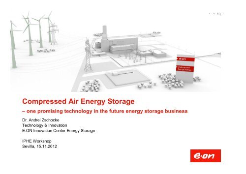
<strong>Compressed</strong> <strong>Air</strong> <strong>Energy</strong> <strong>Storage</strong><br />
<strong>–</strong> <strong>one</strong> <strong>promis<strong>in</strong>g</strong> <strong>technology</strong> <strong>in</strong> <strong>the</strong> future energy storage bus<strong>in</strong>ess<br />
Dr. Andrei Zschocke<br />
Technology & Innovation<br />
E.ON Innovation Center <strong>Energy</strong> <strong>Storage</strong><br />
IPHE Workshop<br />
Sevilla, 15.11.2012
<strong>Energy</strong> storage technologies at E.ON<br />
2<br />
Proven Technology - Potential for improvement - New Technology<br />
Availability, Specification, Cost Effectiveness, Acceptance, Dimension<br />
Battery Capacitor<br />
Heat Fly wheel<br />
Pumped <strong>Storage</strong> P.<br />
(A) CAES<br />
Power to Gas to Grid<br />
or to Caverns or to Power
E.ON Gas <strong>Storage</strong> is <strong>the</strong> host<strong>in</strong>g unit for <strong>in</strong>novation<br />
<strong>in</strong> energy storage bus<strong>in</strong>ess<br />
Key figures<br />
work<strong>in</strong>g gas <strong>in</strong> bill. m³<br />
Germany and Austria:<br />
E.ON Gas <strong>Storage</strong> GmbH<br />
Status 8,5<br />
Projects 1,3<br />
Hungary: E.ON Földgáz <strong>Storage</strong><br />
Status 4,2<br />
Projects 0,0<br />
UK: E.ON Gas <strong>Storage</strong> UK<br />
Status 0,2<br />
Projects 0,0
Estimated development status of<br />
storage technologies (selection)<br />
4<br />
ic<br />
a<br />
l<br />
n<br />
a<br />
h<br />
c<br />
m<br />
e<br />
a<br />
l<br />
m<br />
ic<br />
c<br />
h<br />
e<br />
l<br />
m<br />
a<br />
r<br />
t<br />
h<br />
e<br />
Research & Development<br />
A-CAES CAES+<br />
CAES<br />
o<strong>the</strong>r<br />
PEM<br />
Elektrolysis<br />
PCM<br />
Redox-Flow<br />
undergr.<br />
H 2<br />
Li-Ion<br />
Salt<br />
Bus<strong>in</strong>ess<br />
Na S<br />
Alkali<br />
Elektrolyis<br />
PSP<br />
Water<br />
Plumb<br />
undergr.<br />
CH 4
Compar<strong>in</strong>g <strong>the</strong> energy content<br />
5<br />
Vessel, 150.000 t hard coal, 540 GWh el<br />
Gas <strong>Storage</strong>: 260 GWh<br />
Hydrogen storage: 84 GWh<br />
Waldeck:<br />
PSP<br />
4,3 GWh<br />
total<br />
6 h<br />
CAES Huntorf 0,9 GWh<br />
5 d<br />
1,4 h<br />
Assumption:<br />
over which a<br />
Period<br />
MW generation<br />
800<br />
plant can be fueled<br />
17 d<br />
- for hydrogen and UGS respectively small size<br />
caverns of 300.000 m 3 volume (=Huntorf),<br />
-Efficiency gas generation: 0,6<br />
35 d
Which <strong>technology</strong> fits best to which problem?<br />
-don’t compare “apples with pears”<br />
Capacity<br />
H 2<br />
CAES<br />
PHS<br />
Efficiency (Power to Power)<br />
Battery<br />
� Capacity<br />
� Power<br />
� Ramp-up time<br />
� Efficiency<br />
� Availability<br />
� Costs<br />
� Acceptance<br />
� …and 50 more!
Costs<br />
The general concept of CAES<br />
Huntorf<br />
(1978)<br />
Efficiency<br />
Our goal<br />
McIntosh<br />
(1992)<br />
CAESplus<br />
60 % 70 %
Huntorf as diabatic CAES is state of <strong>the</strong> art<br />
c<br />
o<br />
m<br />
p<br />
e<br />
r<br />
s<br />
io<br />
n<br />
a<br />
t<br />
h<br />
e<br />
n<br />
a<br />
t<br />
.<br />
g<br />
a<br />
s<br />
o<br />
n<br />
n<br />
s<br />
p<br />
a<br />
e<br />
x<br />
600-1000 m depth<br />
i<br />
Huntorf
Huntorf as diabatic CAES is state of <strong>the</strong> art<br />
Huntorf
Huntorf CAES <strong>–</strong> Key figures<br />
In operation s<strong>in</strong>ce 1978<br />
Power 290 MW<br />
Production time 4h<br />
Efficiency 42%<br />
Ramp up time 10 m<strong>in</strong>.<br />
Ramp up time, warm start 6 m<strong>in</strong>.<br />
<strong>Air</strong> production rate 417 kg/s<br />
Compression power 60 MW<br />
Depth of Cavern 650 m<br />
Cavern pressure 43-70 bar<br />
Start per year 100-200<br />
10<br />
Diabatic system <strong>–</strong> compression waste heat is not used<br />
Note: ideal cavern depth for CAES is<br />
shallower than for <strong>the</strong> purpose of<br />
underground gas storage<br />
Comparison of <strong>the</strong> two CAES sites<br />
Huntorf McIntosh<br />
Power 290 MW 110 MW<br />
Prod. Period 4 h 26 h
<strong>Energy</strong> streams of <strong>the</strong> diabatic system<br />
Diabatic CAES Comparison of diabat with adiabat<br />
Compression<br />
Power 67 MW<br />
Cool<strong>in</strong>g<br />
65 MW<br />
Electric Power<br />
293 MW<br />
Gas 456 MW<br />
Loss of Heat<br />
172 MW<br />
Diabat Adiabat<br />
Compress. 70 MW 150 MW<br />
Load time 10 h 10 h<br />
Compression <strong>Energy</strong> 700 MWh 1500 MWh el<br />
Production <strong>Energy</strong> 1000 MWh el 1000 MWh el<br />
<strong>Storage</strong> Vol. 324 000 m 3 416000 m 3<br />
11
Adiabatic CAES (A-CAES)<br />
C<br />
o<br />
m<br />
p<br />
e<br />
r<br />
s<br />
io<br />
n<br />
o<br />
n<br />
i<br />
n<br />
s<br />
p<br />
a<br />
E<br />
x
Cavern<br />
CAESplus concept<br />
Atm.<br />
40°C / 80 bara<br />
Heat storage<br />
LP<strong>–</strong>Comp. HP<strong>–</strong>Comp.<br />
> 400°C, 80 bar<br />
Motor<br />
Gen<br />
HP - Exp.<br />
Adiabatic<br />
stage<br />
Gen<br />
Gas<br />
Exhaust<br />
GT
Low Temperature CAES (LT CAES)<br />
C<br />
o<br />
m<br />
p<br />
e<br />
r<br />
s<br />
io<br />
n<br />
o<br />
n<br />
n<br />
s<br />
p<br />
a<br />
E<br />
x<br />
600-1000 m depth<br />
i<br />
to use water as heat storage<br />
Allows<br />
medium.<br />
Requires more compression stages.
The Challenge: Which is <strong>the</strong> appropriate heat storage?<br />
<strong>in</strong>sulation<br />
steel l<strong>in</strong>er<br />
(airtight)<br />
ground surface<br />
± 0 m<br />
40 m<br />
36 m<br />
4 m<br />
re<strong>in</strong>forced concrete<br />
3 m 1 m<br />
4 m<br />
symmetric axis<br />
10<br />
m<br />
9 m<br />
5 m<br />
22 m<br />
foundation<br />
re<strong>in</strong>forced concrete<br />
active cool<strong>in</strong>g<br />
−4 −4 m<br />
Pressure tank concrete<br />
Oil or molten salt
Occurrence of salt deposits <strong>in</strong> Europe as geographical<br />
constra<strong>in</strong> for cavern based CAES<br />
� Potential for w<strong>in</strong>d power matches partly<br />
with <strong>the</strong> occurrence of salt deposits.<br />
� It complements geographically<br />
pumped hydro.<br />
� Potential is very high, however, <strong>the</strong>re is a<br />
geographical constra<strong>in</strong>.<br />
Artificial pressure tanks<br />
are <strong>the</strong> alternative.<br />
16
Which is <strong>the</strong> best CAES concept?<br />
Today Choices for tomorrow<br />
Diabatic CAES<br />
Huntorf, McIntosh<br />
HT Adiabatic CAES<br />
heat storage<br />
CAESplus<br />
Gas fir<strong>in</strong>g, heat storage<br />
LT adiabatic CAES<br />
Low temperature, adiabatic<br />
CCGT with CAES<br />
Comb<strong>in</strong><strong>in</strong>g everyth<strong>in</strong>g<br />
1. Large scale solutions require salt caverns.<br />
2. High temperature requires <strong>in</strong>novative comp<strong>one</strong>nts.<br />
3. Low temperature solutions can use water as storage medium.<br />
4. High temperature solutions are <strong>the</strong> choice to co-fire gas.<br />
Identification of <strong>the</strong> „best“ design<br />
5-10 MW<br />
pilot<br />
-Spot market<br />
-Balanc<strong>in</strong>g market<br />
-Structur<strong>in</strong>g RE
Fur<strong>the</strong>r example: E.ON PtG-Pilot "Falkenhagen"<br />
Key Parameters<br />
� Power: 2 MW el<br />
� Hydrogen production: 360 m³/h<br />
� Fed <strong>in</strong>to <strong>the</strong> local gas grid (ONTRAS)<br />
� Planned start of operation Q3/2013<br />
� Owner is E.ON Gas <strong>Storage</strong><br />
Goals<br />
� Demonstration of <strong>the</strong> process cha<strong>in</strong><br />
� Optimize operational concept<br />
(fluctuat<strong>in</strong>g power from w<strong>in</strong>d vs.<br />
chang<strong>in</strong>g gas feed)<br />
� Ga<strong>in</strong> experience <strong>in</strong> <strong>technology</strong>, costs,<br />
consent<strong>in</strong>g<br />
18<br />
Meter<strong>in</strong>g<br />
pipel<strong>in</strong>e<br />
connection<br />
voltage<br />
Low<br />
supply<br />
Control<br />
Power supply<br />
Electrolysis
Thank you for your attention!
Summary<br />
<strong>Energy</strong> storage is needed to <strong>in</strong>tegrate <strong>in</strong>termittent<br />
renewable energy generation.<br />
CAES has <strong>the</strong> potential to be a competitive solution<br />
among batteries, power to gas, pumped storage plants<br />
and o<strong>the</strong>rs. Different technologies render different<br />
services on spot and reserve markets.<br />
CAES can also be built for decentralized applications. Which of<br />
variants is best, is not clear today.<br />
Decentralized storage plants are widely accepted <strong>in</strong> <strong>the</strong><br />
public


