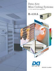
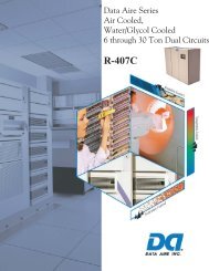
Data Aire Series Air Cooled, Water/Glycol Cooled 6 through 30 ton ...
Data Aire Series Air Cooled, Water/Glycol Cooled 6 through 30 ton ...
Data Aire Series Air Cooled, Water/Glycol Cooled 6 through 30 ton ...

You also want an ePaper? Increase the reach of your titles
YUMPU automatically turns print PDFs into web optimized ePapers that Google loves.
OPTIONS<br />
Energy Saver Coil - The environmental control units shall be provided with an Energy Saver Coil. The Energy Saver Coil shall<br />
be an integral part of the unit and will be capable of providing the total cooling capacity. Whenever the incoming water/glycol<br />
temperature is below the setpoint of the water changeover thermostat, Energy Saver cooling shall be available.<br />
The Energy Saver shall operate in the following range: Return air setpoint plus deadband plus 2 degrees.<br />
The Energy Saver shall operate providing there is a need for cooling. The valve shall open at setpoint plus deadband. The valve<br />
shall modulate as long as the space is between setpoint plus deadband plus 2 degrees. If the temperature falls below the deadband<br />
minus setpoint, the valve shall close and the space shall be considered satisfi ed. While still in Energy Saver with the valve modulating,<br />
if the temperature goes beyond setpoint plus deadband plus 2 degrees, the Energy Saver valve shall close and mechanical<br />
(DX) cooling shall begin.<br />
The Energy Saver Coil shall include 3-way pressure control valves on the condenser circuits and 3-way valve on the economy coil.<br />
Common piping for the energy coil and condensers shall be provided.<br />
Energy Saver/Compressor Supplement - Units with Energy Saver shall be provided with compressor supplement if the Energy<br />
Saver is not suffi cient as a stand alone system. When the incoming water/glycol temperature is below the setpoint of the water<br />
changeover thermostat, the Energy Saver shall be enabled (even if there is no call for cooling). Upon a call for cooling (setpoint<br />
plus deadband), the valve shall open proportionally - 10% for each 0.1° above setpoint plus deadband. The compressor shall<br />
come on at setpoint plus deadband plus 1.3° (the valve shall be 100% open at this point). The compressor shall go off at setpoint<br />
plus 1.3° The valve shall close proportionally - 10% for each 0.1° below setpoint. An air discharge sensor shall be factory<br />
mounted.<br />
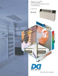
Auxiliary Chilled <strong>Water</strong> Coil - Units shall be provided with an Auxiliary Chilled <strong>Water</strong> Coil. The existing chilled water loop<br />
shall be utilized with the Auxiliary Chilled water coil. Units shall operate using the chilled water for cooling. Upon a loss of<br />
water fl ow or an increase in room temperature the system shall bring on compressor (DX) cooling. Separate piping shall be provided<br />
for the chilled water coil and refrigeration connections.<br />
Remote Temperature and Humidity Sensors - Units shall be provided with remote temperature and humidity sensors. Sensors<br />
shall be provided in a plastic case for remote mounting. 25 feet of shielded cable shall be provided for fi eld wiring.<br />
Disconnect - The environmental control unit shall include a nonautomatic disconnect switch mounted in the high voltage section<br />
of the electrical panel. The operating mechanism shall prevent access to the high voltage electrical components until switched<br />
to the “OFF” position. The operating mechanism shall protrude <strong>through</strong> the decorative door.<br />
Smoke Detector - The environmental control unit shall be provided with a smoke detector. The smoke detector shall be mounted<br />
with the sensing element in the return air stream. When the smoke detector is activated, it shall immediately shut down the<br />
unit.<br />
Condensate Pump - Units shall be provided with condensate pumps. Pumps shall be factory mounted/wired or shipped loose<br />
for fi eld installation and shall include sump, motor, and automatic control. The pumps shall be rated for 1<strong>30</strong> GPH @ 20 foot<br />
maximum head (40 GPH @ 20 feet with check valve).<br />
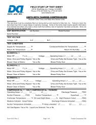
Tandem Scroll Compressors - Provide units with tandem hermetic scroll compressors with two step modulation for stage control.<br />
Each circuit shall contain two scroll compressors. Modulation shall allow one or both compressors (per circuit) to run depending<br />
upon the load of the system, resulting in part-load effi ciency equal to full load effi ciency.<br />
67