microprocessor based digital alarm system alert - Medical Gas Experts
microprocessor based digital alarm system alert - Medical Gas Experts
microprocessor based digital alarm system alert - Medical Gas Experts

You also want an ePaper? Increase the reach of your titles
YUMPU automatically turns print PDFs into web optimized ePapers that Google loves.
MICROPROCESSOR BASED<br />
DIGITAL ALARM SYSTEM<br />
ALERT- 2<br />
Installation and Maintenance Manual v4.0
Table of Contents<br />
USER RESPONSIBILITY .................................................................. 4<br />
INTRODUCTION ............................................................................... 5<br />
FEATURES ................................................................................... 6<br />
DESCRIPTION OF THE ALARM ...................................................... 7<br />
SHIPMENT DETAILS .................................................................... 7<br />
THE ALARM BACK BOX............................................................... 7<br />
THE FRAME/MODULE ASSEMBLY ............................................. 7<br />
DESCRIPTION OF MODULES ......................................................... 8<br />
COMMON TO ALL ALARMS......................................................... 8<br />
SYSTEM POWER SUPPLY. ..............................................................8<br />
ANNUNCIATOR MODULE. ...............................................................8<br />
BLANK MODULE. ..............................................................................9<br />
AREA ALARM ............................................................................... 9<br />
AREA DISPLAY MODULE. ................................................................9<br />
SENSOR MODULE. ...........................................................................9<br />
MASTER ALARM ......................................................................... 10<br />
MASTER STATUS MODULE. ...........................................................10<br />
COMPUTER INTERFACE MODULE. ...............................................10<br />
INSTALLATION ................................................................................ 11<br />
THE ALARM BOX ........................................................................ 11<br />
LOCAL SENSOR ONLY ...................................................................11<br />
STANDING PRESSURE TEST .........................................................11<br />
FRAME/MODULE ASSEMBLY .................................................... 11<br />
SENSOR ...................................................................................... 12<br />
LOCAL ..............................................................................................12<br />
REMOTE ...........................................................................................12<br />
WIRING ............................................................................................. 13<br />
SYSTEM POWER SUPPLY ......................................................... 13<br />
ANNUNCIATOR MODULE ........................................................... 13<br />
SENSOR MODULE ...................................................................... 14<br />
LOCAL ..............................................................................................14<br />
REMOTE ...........................................................................................14<br />
AREA DISPLAY MODULE ........................................................... 15<br />
MASTER STATUS MODULE ....................................................... 15<br />
COMPUTER INTERFACE MODULE ........................................... 15<br />
CLOSING THE FRAME/MODULE ASSEMBLY ........................... 15<br />
FIELD ADJUSTMENTS.................................................................... 16
Alert - 2 Series<br />
ANNUNCIATOR MODULE .........................................................................16<br />
THE AREA DISPLAY MODULE ....................................................................... 17<br />
PRESSURE ONLY .............................................................................. 17<br />
HIGH / LOW <strong>alarm</strong> set point adjustments .......................................... 17<br />
PSI / KPA / BAR selection ............................................................... 18<br />
VACUUM ONLY ................................................................................... 18<br />
LOW vacuum <strong>alarm</strong> set-point adjustment ......................................... 18<br />
InchHg / KPA / BAR selections ......................................................... 19<br />
COMMON SETTINGS FOR PRESSURE AND VACUUM ......................... 20<br />
Repeat Alarm Enable/Disable .......................................................... 20<br />
SETTING FACTORY DEFAULT ....................................................... 20<br />
SETTING GAS IDENTIFICATION SWITCHES ........................................ 21<br />
MASTER STATUS MODULE ........................................................... 22<br />
REPEAT ALARM ................................................................................. 22<br />
SIGNAL INPUT SELECTION ................................................................. 20<br />
MAINTENANCE MODE ........................................................................ 22<br />
TROUBLE SHOOTING GUIDE ...................................................... 24<br />
TABLE OF ERROR CODES ................................................................ 26<br />
MODEL NUMBERS AND SPARE PARTS ...................................................... 27<br />
DIMENSIONS ............................................................................................... 30<br />
APPENDIX A - WIRING - POWER SUPPLY ................................................... 32<br />
APPENDIX B - WIRING - ANNUNCIATOR ..................................................... 33<br />
APPENDIX C - WIRING - AREA LOCAL SENSOR .......................................... 34<br />
APPENDIX D - WIRING - AREA REMOTE SENSOR ...................................... 35<br />
APPENDIX E - WIRING - AREA to MASTER .................................................. 36<br />
APPENDIX F - WIRING - ABNORMAL CONDITION ....................................... 37<br />
APPENDIX G - WIRING - AREA SLAVE.......................................................... 38<br />
APPENDIX H - WIRING - MASTER MODULE ................................................ 39<br />
APPENDIX I - WIRING - COMPUTER INTERFACE MODULE ........................ 40<br />
APPENDIX J - WIRING - MASTER TO SLAVE ............................................... 41<br />
APPENDIX K - TECHNICAL SPECIFICATION ............................................... 42<br />
Model Number of this Manual: A2-MAN-ALM-ENG JUNE-2000<br />
Page: 3
Amico Microprocessor Based Alarm<br />
USER RESPONSIBILITY<br />
The information contained in this Installation and Operation Maintenance<br />
Manual, pertains only to the ALERT-2 <strong>microprocessor</strong> <strong>based</strong> <strong>digital</strong> <strong>alarm</strong>.<br />
This product will perform to conformity with the descriptions contained in this<br />
manual, when assembled, operated, maintained and serviced in accordance<br />
with the installation instructions provided.<br />
The <strong>alarm</strong> must be checked periodically. Parts that are broken, missing,<br />
worn, distorted or contaminated, must be replaced immediately. Should such<br />
repair or replacement become necessary, please contact Amico Corporation<br />
or their distributors.<br />
All <strong>alarm</strong>s should not be repaired, or altered without prior written or verbal<br />
approval of Amico Corporation or it’s distributors. Failure to comply will void<br />
all warranty on the <strong>alarm</strong>.<br />
Statements in this manual preceded by the words WARNING, CAUTION,<br />
DANGER and NOTE are of special significance. Please read these sections<br />
carefully.<br />
Page: 4<br />
WARNING: denotes steps which can prevent injury.<br />
CAUTION: denotes steps which can prevent damage to equipment.<br />
DANGER: denotes steps which can prevent electrical shock to equipment<br />
or to prevent serious injury and/or death.
INTRODUCTION<br />
Alert - 2 Series<br />
The AMICO medical gas <strong>alarm</strong> <strong>system</strong> (ALERT-2) incorporates the latest<br />
<strong>microprocessor</strong> technology for <strong>alarm</strong> and surveillance <strong>system</strong>s. The <strong>alarm</strong><br />
has been designed to provide user flexibility and reliability. This manual will<br />
enable the customer to install, use and maintain the <strong>alarm</strong> properly.<br />
All <strong>Gas</strong>es or Vacuum are displayed with large red LED’s for clear visibility. To<br />
facilitate the monitoring function by hospital personnel, a trend bar is provided<br />
to show the direction of the gas/vacuum pressure. Under normal<br />
operation, the gas trend indicator will be in the GREEN - OK position. If the<br />
gas pressure approaches <strong>alarm</strong> condition, the trend indicator will display a<br />
YELLOW - Caution indicator. If an <strong>alarm</strong> condition occurs, a RED - Alarm<br />
indicator will be displayed and the buzzer will sound.<br />
There are two buttons located on the front face of the Annunciator module.<br />
They are the: “PUSH TO TEST” and “ALARM SILENCE” buttons. The function<br />
of the “Push to Test” button is to verify that the buzzer and all the <strong>alarm</strong><br />
LED’s are in normal working condition. The function of the “Alarm Silence”<br />
button is to silence an <strong>alarm</strong> that has occurred.<br />
A master status module monitors source equipment such as: Oxygen, Nitrous<br />
Oxide, Air compressors, Vacuum pumps, Air dryers, high/low pressure<br />
switches, etc. This module can be connected to a “Building Management<br />
System”, with a piggy-back computer interface board, that attaches to the<br />
master module.<br />
Page: 5
Amico Microprocessor Based Alarm<br />
Page: 6<br />
FEATURES INCLUDE:<br />
n Individual Microprocessor on each display, sensor and master<br />
module.<br />
n <strong>Gas</strong> specific sensors can be mounted locally or remote, up to 5,000<br />
feet, [1,500m] utilizing 22 gauge twisted pair (2 shielded wires).<br />
n DISS gas specific sensor housed in a tamper proof enclosure.<br />
n True <strong>digital</strong> LED display and trend indicator for each service monitored.<br />
n Illuminated LED display that is visible at an angle or in dim lighting<br />
conditions.<br />
n PSI, kPa or BAR display (switch selected).<br />
n Self diagnostic circuitry with error display for problem identification.<br />
n Highly accurate Solid State Pressure piezo-resistive transducer.<br />
n Adjustable repeat <strong>alarm</strong> (1 to 60 minutes/or off).<br />
n Dry contacts for remote monitoring of High and Low <strong>alarm</strong> status on<br />
the display module.<br />
n Modules are factory mounted on a hinged frame assembly for ease<br />
of installation and maintenance.<br />
n Field programmable push buttons for adjustment of HI and LOW<br />
set-points on display module.<br />
n Area <strong>alarm</strong>s available in 1 to 6 display modules.<br />
n Master <strong>alarm</strong>s available in 10 to 60 points.<br />
n Area Modules can be intermixed with Master Modules to create a<br />
combination <strong>alarm</strong>.<br />
n Built-In relay for remote annunciator applications.<br />
n Area Module indication for calibration (flashing bar graph).
DESCRIPTION OF THE ALARM<br />
SHIPMENT DETAILS<br />
When you receive an ALERT-2 series <strong>alarm</strong> from Amico Corporation, the<br />
package will consist of two main sections; the Alarm Back Box and the<br />
Frame/Module Assembly. The Frame/Module assembly will be preconfigured,<br />
with the appropriate display modules, <strong>based</strong> upon the customer’s<br />
specifications<br />
THE ALARM BACK BOX<br />
The Alarm Back Box contains the System Power Supply with an ON/OFF<br />
switch, a built-in fuse, terminal blocks and a voltage selector switch (115<br />
VAC, or 220 VAC). The back box also incorporates the pipe stubs for applications<br />
that require locally (in box) mounted sensors.<br />
THE FRAME/MODULE ASSEMBLY<br />
The Frame/Module Assembly consists of the frame and all the modules that<br />
are pre-assembled to the customers specification. The hinged frame is<br />
designed to swing down from the back box to facilitate installation and servicing<br />
of the <strong>alarm</strong>. This design will reduce installation time and eliminate the<br />
risk of improper installation since all the modules are connected and tested at<br />
the factory.<br />
Alert - 2 Series<br />
Page: 7
Amico Microprocessor Based Alarm<br />
Page: 8<br />
DESCRIPTION OF MODULES<br />
The ALERT-2 <strong>alarm</strong> is divided into (7) main modules:<br />
COMMON TO ALL ALARMS<br />
1. SYSTEM POWER SUPPLY.<br />
The System Power Supply has been pre-installed into the back box<br />
assembly. This unit contains the voltage selector switch that enables the<br />
voltage to be set to 115 VAC/60 Hz or 220 VAC/50 Hz. The System Power<br />
Supply converts the AC voltage supply to the <strong>alarm</strong> into two voltages: 5<br />
VDC (regulated) required by the <strong>microprocessor</strong> hardware and 12 VDC<br />
(unregulated) required by the buzzer and the LED’s. This unit also contains<br />
the main ON/OFF power switch, the transformer, the heat sink, the<br />
main fuse and fuse cover, the rectifying circuitry, the terminal blocks and<br />
the low voltage DC power cable for connecting this unit to the annunciator<br />
module. The System Power Supply can be easily removed and reinstalled<br />
by unscrewing it from the back box.<br />
2. ANNUNCIATOR MODULE.<br />
The Annunciator Module contains the buzzer, a “Power On” LED, the<br />
“PUSH TO TEST” and the “ALARM SILENCE” buttons. The function of the<br />
“PUSH TO TEST” button is to verify that the buzzer and all the LED’s are<br />
in working condition. An <strong>alarm</strong> will be heard when this button is pushed<br />
and all the LED’s will light up. When the button is released, the <strong>alarm</strong> will<br />
silence. The “ALARM SILENCE” button is used to silence an <strong>alarm</strong> that<br />
has occurred. This module also contains a fail-safe relay that deenergizes<br />
when the buzzer is activated. This relay can be used with the<br />
“Amico remote buzzer”, for applications requiring a remote audible <strong>alarm</strong>,<br />
for connection to an other Amico Alarm or a Building Management<br />
System.<br />
3. BLANK MODULE.<br />
The Blank Module is used as a filler board for future provisions of the<br />
<strong>alarm</strong>.
AREA ALARM<br />
4. AREA DISPLAY MODULE.<br />
The Area Display Module provides a <strong>digital</strong> display of the actual<br />
pressure/vacuum of a gas being monitored. In addition a gas<br />
trend indicator bar with HIGH and LOW <strong>alarm</strong>s are displayed.<br />
The trend bar has three coloured LED’s: GREEN for Normal<br />
condition, YELLOW for Caution condition, and RED for high and<br />
low Alarm conditions.<br />
Each display module contains a gas specific colour coded label<br />
(USA or ISO colours are available). A space is also provided, at<br />
the base of the module, to identify the location that the display<br />
module monitors. The display module is field adjustable for<br />
pressure/vacuum settings, repeat <strong>alarm</strong>, and units of measure.<br />
Whenever the module is in calibration mode, the bargraph is<br />
flashing, indicating the calibration mode. Dry contacts for high<br />
and low <strong>alarm</strong>s are available for remote monitoring of each<br />
module.<br />
5. SENSOR MODULE.<br />
The Sensor Module contains the transducer which converts the pressure/<br />
vacuum pressure source into a <strong>digital</strong> signal that is displayed on the<br />
display module. The sensor module is housed in a white ABS plastic<br />
fire rated enclosure to reduce the risk of tampering. Each sensor is<br />
clearly labelled and colour coded for the gas or vacuum being monitored.<br />
The sensor module contains a gas specific DISS fitting to<br />
ensure correct connection of the proper sensor to the respective gas.<br />
Each sensor has been factory calibrated for the specific gas shown<br />
on the sensor housing. If it is not connected to the appropriate gas<br />
display module, an error message (E02) will be displayed.<br />
MASTER ALARM<br />
Alert - 2 Series<br />
Page: 9
Amico Microprocessor Based Alarm<br />
Page: 10<br />
6. MASTER STATUS MODULE.<br />
Each Master Status Module will continuously monitor up to 10 signals<br />
from source equipment and pressure switches. If any of the signals being<br />
monitored go into an <strong>alarm</strong> condition, a red LED will illuminate and the<br />
audible <strong>alarm</strong> will sound. The module has a slow and a rapid flashing LED<br />
rate. The last <strong>alarm</strong> condition always flashes at a rapid rate, while the<br />
previously acknowledged <strong>alarm</strong>s always flash at a slow rate.<br />
PLEASE NOTE: Contacts located on back of module are Dry Contacts<br />
only. DO NOT apply any voltage.<br />
7. COMPUTER INTERFACE MODULE.<br />
The Computer Interface Module is a piggyback board that fits on top of the<br />
master status module. This module plugs into the status module via a<br />
connector, located at the bottom end of the status module. There are four<br />
mounting screws provided to secure this module to the status module.<br />
This module provides dry contacts for interface to a “Building Management<br />
System”. The module is “Fail-Safe”, closed circuit monitoring.
INSTALLATION<br />
THE ALARM BOX<br />
Install the back-box to the studs of the wall at the desired height.<br />
Ensure that the box is securely in place. The mounting brackets are<br />
adjustable to suit the thickness of the wall. MAKE SURE the box is<br />
parallel, squared and flush with the finished wall surface, to ensure<br />
that the frame assembly will fit properly.<br />
FOR LOCAL SENSOR ONLY<br />
If the sensors are to be mounted locally (inside the back box), the pipe<br />
stubs must be connected to the pipeline. Using silver-brazing techniques,<br />
connect each pipe stub to it’s appropriate gas or vacuum while<br />
ensuring that the bottom of the pipe stub is wrapped with a damp cloth.<br />
BE CAREFUL not to damage the DISS check-valve by overheating the<br />
lower portion of the copper pipe. When the brazing of pipe stubs has<br />
been completed, the <strong>system</strong> can be pressure tested.<br />
STANDING PRESSURE TEST<br />
Perform a standing pressure test on the piping <strong>system</strong> as per NFPA -<br />
99 “Health Care Facilities” or CSA-Z305.1 “Nonflammable <strong>Medical</strong> <strong>Gas</strong><br />
Piping Systems”. Inspect all joints for leaks and make certain each gas<br />
is piped to a correspondingly labelled gas service.<br />
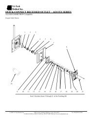
FRAME/MODULE ASSEMBLY<br />
1. Remove the frame/module assembly from its protective box.<br />
2. Mount the frame/module assembly<br />
by lining up the screw holes<br />
located at the bottom of the frame<br />
hinges with those located on the<br />
bottom of the box.<br />
3. With a screwdriver, attach the<br />
frame assembly into the back box<br />
assembly using the screws<br />
provided with the frame. Attach<br />
the guide wires located on the<br />
frame to the back box, to prevent<br />
the frame assembly from opening<br />
more than 90 degrees. Opening<br />
the frame will expose the inner<br />
circuitry of the frame/module<br />
assembly.<br />
Alert - 2 Series<br />
Page: 11
Amico Microprocessor Based Alarm<br />
Page: 12<br />
CAUTION: The <strong>microprocessor</strong> circuitry on the ALERT-2 <strong>alarm</strong> contains<br />
sophisticated integrated semiconductors. If it becomes necessary<br />
to remove a module, PLEASE hold the boards by the edges. DO NOT<br />
TOUCH any of the components on the board. Static discharge can<br />
cause the modules to malfunction, or become damaged.<br />
SENSOR<br />
LOCAL (In the Back Box)<br />
1. Locate the gas specific<br />
sensor module to be installed.<br />
2. In the back box, there are<br />
colour coded gas labels<br />
located under the DISS<br />
Demand check valves. Each<br />
label identifies where each<br />
sensor module is to be<br />
placed.<br />
3. The sensor module contains<br />
a gas specific DISS fitting.<br />
Push the sensor module<br />
hex-nut and nipple adapter<br />
up into the demand checkvalve.<br />
With a wrench, tighten the nut so that it makes a good<br />
seal.<br />
NOTE: Pressure on sensors are not to exceed<br />
250psi for Pressure and Vacuum sensors<br />
400psi for Nitrogen<br />
sensors.<br />
REMOTE (Outside the Back<br />
Box)<br />
1. Connect a Tee (supplied<br />
by others) to the pipeline<br />
with a 1/4" NPT female<br />
connection that will accept<br />
the DISS Demand checkvalve.<br />
2. Locate the gas specific<br />
sensor module to be installed.<br />
3. Thread the DISS Demand check-valve into the correct gas pipe<br />
line.
4. The sensor module contains a gas specific DISS fitting. Push the<br />
sensor module hex-nut and nipple adapter up into the demand<br />
check-valve. With a wrench, tighten the nut so that it makes a<br />
good seal.<br />
WIRING<br />
SYSTEM POWER SUPPLY<br />
TURN OFF THE POWER SWITCH, BEFORE CHANGING ANY MOD-<br />
ULES AND/OR DISCONNECTING ANY CABLES, OR ELSE THE<br />
FUSE WILL BLOW TO PROTECT THE CIRCUITRY.<br />
1. Ensure that the ON/OFF switch is in the OFF position. Also ensure<br />
that the voltage selector switch is set to the correct voltage position<br />
(115 VAC or 220 VAC).<br />
2. Through the top left side of the back box, bring in the AC power<br />
wires. Knockouts are provided for making conduit connections to<br />
the box. All wiring is to be installed according to local and national<br />
codes.<br />
3. Connect the AC power to the terminal blocks as shown in the<br />
wiring diagram in Appendix A.<br />
ANNUNCIATOR MODULE<br />
1. The Annunciator Module has a female receptacle located at the<br />
top right side of the board (J1).<br />
2. Connect the DC power cable from the System Power Supply into<br />
the receptacle connection located on the annunciator module. The<br />
connector is keyed and can only be plugged in one way, (Appendix<br />
B).<br />
Alert - 2 Series<br />
Page: 13
Amico Microprocessor Based Alarm<br />
Page: 14<br />
SENSOR MODULE<br />
LOCAL (In the Back Box)<br />
1. The sensor module is provided with a 20" [0.5m] twisted<br />
pair of wires. One wire is red (positive) and the other wire is<br />
black (negative). Connect the wires to the display module<br />
as shown in Appendix C. Take the red wire from the sensor<br />
and attach it to terminal “Sensor +”on the display module.<br />
Take the black wire from the sensor and attach it to terminal<br />
“Sensor -”. The terminal block on the display module is<br />
clearly marked for proper connection of the sensor wires.<br />
2. Repeat the above procedures with the remaining sensor<br />
modules.<br />
REMOTE (Outside the Back Box)<br />
NOTE:<br />
1. The sensor module is provided with a 20" [0.5m] twisted<br />
pair of wires. Connect the wires to a junction box (not<br />
supplied) located near the sensor as per the wiring diagram<br />
in Appendix D.<br />
2. Connect a shielded twisted pair cable from the junction box<br />
to the back box assembly. Knockouts are provided throughout<br />
the <strong>alarm</strong> back box. Up to 5,000 feet [1,500m] of 22<br />
Gauge shielded twisted pair cable can be used.<br />
3. Connect the red wire from the cable to the terminal on the<br />
display module marked ”Sensor +”. Connect the black wire<br />
to terminal “Sensor -”.<br />
4. Repeat the above procedures with the remaining sensor<br />
modules using the wiring diagram in Appendix D.<br />
When remote sensors are used, a shielded twisted pair<br />
cable is required (BELDEN #8760 or equivalent, supplied<br />
by others). Ensure that the proper gas sensor module is<br />
connected to it’s corresponding area display module,<br />
otherwise an error message (E02) will be displayed on the<br />
Area Display module.
AREA DISPLAY MODULE<br />
1. If the dry contacts for High and Low <strong>alarm</strong> are to be used for remote<br />
monitoring, connect the wires to the appropriate terminals, C, NO or<br />
NC, using the diagram in Appendix C or D.<br />
2. See Appendix H for contact rating.<br />
MASTER STATUS MODULE<br />
1. Pull the remote signal wires into the <strong>alarm</strong> panel. Make the connections<br />
to the terminal blocks located on the side of the status module.<br />
The wiring is fail-safe normally closed (NC) connections from the<br />
source equipment. The signal level is 5 VDC.<br />
2. Make the appropriate wiring connections as per the wiring diagram<br />
in APPENDIX E.<br />
3. ENSURE that the unused terminals in the master module are<br />
jumpered. If this is not done, the terminals that have not been<br />
jumpered will go into <strong>alarm</strong>.<br />
COMPUTER INTERFACE MODULE<br />
1. Pull the remote signal wires from the “Building management <strong>system</strong>”<br />
into the <strong>alarm</strong> panel. Make the connections to the terminal<br />
blocks located on the side of the module. The wiring is fail-safe<br />
normally open, held closed, dry contacts to the monitoring equipment.<br />
2. Make the appropriate wiring connections as per wiring diagram in<br />
Appendix F.<br />
CLOSING THE FRAME/MODULE ASSEMBLY<br />
1. Swing up the frame assembly, ensuring that the stopper wires are<br />
folded into the back box.<br />
2. Screw in the frame module to the top of the back box assembly by<br />
using the screws provided with the frame/module assembly. The<br />
<strong>alarm</strong> is now ready for use!<br />
Alert - 2 Series<br />
Page: 15
Amico Microprocessor Based Alarm<br />
FIELD ADJUSTMENTS<br />
THE ANNUNCIATOR MODULE<br />
NOISE LEVEL CONTROL<br />
Page: 16<br />
Factory Default: 90 Decibles<br />
To decrease noise level:<br />
1. Locate jumper at J5. Move jumper to:<br />
LVL1 = 90 dBa.<br />
LVL2 = 80 dBa.<br />
LVL3 = 70 dBa.<br />
CONTROL OF REMOTE ALARM BUZZER<br />
Factory Default: Normal Condition<br />
To silence remote <strong>alarm</strong> buzzer when silencing the<br />
annunciator module:<br />
1. Locate jumper at J6. Move jumper to:<br />
NORM =<br />
Remote <strong>alarm</strong> buzzer will silence when annunciator<br />
module is silenced.<br />
ALRM =<br />
Remote <strong>alarm</strong> will not silence when annunciator<br />
module is silenced. The buzzer will only silence<br />
when <strong>alarm</strong> condition has been cleared.<br />
LVL1<br />
LVL2<br />
LVL3 J5<br />
SILENCE<br />
TEST<br />
J6<br />
ALRM<br />
NORM
THE AREA DISPLAY MODULE<br />
A dip switch is located on the back of<br />
the display module which is used to<br />
identify the gas of the display<br />
module. The dip-switch contains ten<br />
switch settings.<br />
PRESSURE ONLY<br />
Factory Default:<br />
High = 60 Psi, Low = 40 Psi<br />
Repeat time = 30 min.<br />
Alert - 2 Series<br />
During Programming the “Trend Bar”<br />
will Flash!<br />
1. Set switch #6, #7 and #8 to the ON<br />
position.<br />
2. The LED will display (HI-), followed by the current set point.<br />
Indicating the <strong>system</strong> is ready to accept a new High set point.<br />
Adjust set point, using the “UP” and “DOWN” push buttons, to the<br />
desired value.<br />
3. Set switch #7 to the OFF position.<br />
4. The LED will display (LO-), followed by the current set point.<br />
Indicating the <strong>system</strong> is ready to accept a new Low set point.<br />
Adjust set point, using the “UP” and “DOWN” push buttons, to the<br />
desired value.<br />
5. Set switch #8 to the OFF position.<br />
6. The LED will display (I-I-), followed by the current set point.<br />
Indicating the <strong>system</strong> is ready to accept a new Repeat time set<br />
point. Adjust set point using the “UP” and “DOWN” push buttons,<br />
to the desired value. [(Display dd=Disabled) Range from 1 to 99<br />
Minutes]<br />
7. Set switch #6 to the OFF position.<br />
When you have completed step #7, the display module will automatically<br />
go into a “RESET” mode.<br />
This will store the data that you<br />
had entered.<br />
Page: 17
Amico Microprocessor Based Alarm<br />
Page: 18<br />
PSI / kPa / BAR selection<br />
Factory Default - PSI<br />
For PSI mode, set the switch #4 to the ON position. The LED<br />
PSI indicator located next to the GAS pressure reading will<br />
illuminate.<br />
For kPa mode, set the switch #4 to the OFF position and<br />
switch #9 to the ON position. The LED kPa indicator located<br />
next to the GAS pressure reading will illuminate.<br />
For BAR set the switch #4 to the OFF and the switch #9 to the<br />
OFF position. The LED kPa indicator located next to the GAS<br />
pressure reading will illuminate. (There is no separate indicator<br />
for BAR).<br />
VACUUM ONLY<br />
Vacuum <strong>alarm</strong> set-point adjustment<br />
Factory Default:<br />
High = 30”Hg, Low = 12”Hg<br />
Repeat time = 30 min.<br />
During Programming the “Trend Bar” will Flash!<br />
1. Set switch #6, #7 and #8 to the ON position.<br />
2. The LED will display (HI-), followed by the current set point.<br />
Indicating the <strong>system</strong> is ready to accept a new High set<br />
point. Do not adjust this set point since the High set point is<br />
not used.<br />
3. Set switch #7 to the OFF position.<br />
4. The LED will display (LO-), followed by the current set point.<br />
Indicating the <strong>system</strong> is ready to accept a new Low set<br />
point. Adjust set point, using the “UP” and “DOWN” push<br />
buttons, to the desired value.<br />
5. Set switch #8 to the OFF position.<br />
6. The LED will display (I-I-), followed by the current set point.<br />
Indicating the <strong>system</strong> is ready to accept a new Repeat time<br />
set point. Adjust set point using the “UP” and “DOWN” push<br />
buttons, to the desired value.<br />
[(Display dd=Disabled) Range from 1 to 99 Minutes]<br />
PSI<br />
KPA<br />
BAR
InchHg<br />
KPA<br />
BAR<br />
7. Set switch #6 to the OFF position.<br />
Alert - 2 Series<br />
When you have completed step #7, the display module will<br />
automatically go into a “RESET” mode. This will store the data<br />
that you had entered.<br />
InchHg / KPA / BAR selections<br />
Factory Default - InchHg<br />
For InchHg mode, set the switch #4 to the ON position. The<br />
LED indicating InHg located next to the VACUUM source<br />
reading will illuminate.<br />
For KPA mode, set the switch #4 to the OFF position and the<br />
switch #9 to the ON position. The LED indicating KPA located<br />
next to the VACUUM source reading will illuminate.<br />
For BAR mode, the KPA indicating source must be changed to<br />
BAR by use of a label. Set the switch #4 to the OFF and the<br />
switch #9 to the OFF position. The LED indicating BAR located<br />
next to the VACUUM source reading will illuminate.<br />
COMMON SETTINGS FOR PRESSURE AND VACUUM<br />
Repeat Alarm Enable/Disable<br />
Factory Default - Disable<br />
Disable<br />
Set switch #5 to the OFF position to disable the<br />
repeat <strong>alarm</strong>.<br />
NOTE: When the repeat <strong>alarm</strong> function is disabled,<br />
the <strong>alarm</strong> will not repeat.<br />
Page: 19
Amico Microprocessor Based Alarm<br />
Page: 20<br />
Enable<br />
Enable Mode: (Factory Default 30 min, when enabled).<br />
Set switch #5 to the ON position.<br />
Note: The Module with the Lowest set Repeat Time is<br />
the one that controls the Repeat Time. For example if<br />
one Module is set for 5min and one for 30min and both<br />
are Repeat Alarm enabled, the Alarm will now Repeat<br />
every 5min.<br />
SETTING FACTORY DEFAULT<br />
To quickly reset the module (Pressure or Vacuum) to the factory<br />
default settings as follows:<br />
- Pressure: High set-point 60 Psi, Low set-point 40 Psi.<br />
- Nitrogen & HP Air: High set-point 195 Psi, Low set-point 140 Psi.<br />
- Vacuum: Low set-point 12 inchHg.<br />
- No Repeat <strong>alarm</strong>, but set for 30 min..<br />
1. Set switch #8 to the ON position.<br />
2. Turn the power off (wait 5 seconds) then back on.<br />
3. Set switch #8 to the OFF position.<br />
The module is now in the default mode.
SETTING GAS IDENTIFICATION SWITCHES<br />
Alert - 2 Series<br />
NOTE: DO NOT TAMPER WITH SWITCHES #1, 2 AND 3 ON<br />
THE DIP-SWITCH. TAMPERING WITH THESE POSITIONS<br />
WILL RESULT IN AN ERROR MESSAGE BEING<br />
DISPLAYED (EO2) AND WILL DISABLE THE ELECTRICAL<br />
INTERLOCK FROM THE GAS SPECIFIC SENSOR.<br />
CHANGES TO THESE SWITCHES SHOULD ONLY BE<br />
DONE BY PROPERLY TRAINED PERSONNEL, WHEN<br />
CIRCUIT BOARDS HAVE TO BE CHANGED IN THE FIELD.<br />
Switches # 1, 2 and 3 are used for the gas identification of the<br />
display module. These will be set at the factory and should not<br />
be tampered with in the field.<br />
CHART OF GAS SPECIFIC SETTINGS OF DIP-SWITCHES<br />
Page: 21
Amico Microprocessor Based Alarm<br />
MASTER STATUS MODULE<br />
REPEAT ALARM<br />
Factory Default - Disable<br />
Disable Set switch #1 to the OFF position.<br />
Set switch #2 to the OFF position.<br />
Page: 22<br />
Enable 5 min Set switch #1 to the ON position.<br />
Set switch #2 to the OFF position.<br />
Enable 15 min Set switch #1 to the OFF position.<br />
Set switch #2 to the ON position.<br />
Enable 30 min Set switch #1 to the ON position.<br />
Set switch #2 to the ON position.<br />
SIGNAL INPUT SELECTION<br />
Factory Default - Normally Closed as per NFPA 99 and CSA Z305.1<br />
The Amico <strong>alarm</strong> can detect field devices in the Normally<br />
Open or Normally Closed position.<br />
For Normally Closed Set switch #3 to the OFF position<br />
For Normally Open Set switch #3 to the ON position<br />
MAINTENANCE MODE<br />
Factory Default - Disabled<br />
The Maintenance (or Latch) mode is used to allow hospital personnel<br />
to identify loose wiring or faulty source equipment. By putting the<br />
master module into “Latch” mode, any <strong>alarm</strong>s received; even transient<br />
ones, will be latched-on so that maintenance personnel can<br />
identify the source of the problem. The Maintenance mode will disable<br />
the automatic reset, if a fault condition has been rectified. The <strong>alarm</strong><br />
indicator can only be turned-off by pushing the “<strong>alarm</strong> silence” button<br />
on the annunciator module twice. The “Maintenance” LED will illuminate<br />
whenever the maintenance mode is enabled.
Disable Set switch #4 to the OFF position.<br />
Enable Set switch #4 to the ON position.<br />
Alert - 2 Series<br />
Page: 23
Amico Microprocessor Based Alarm<br />
Page: 24<br />
TROUBLE SHOOTING GUIDE<br />
NOTE: Ensure that the power is turned off before changing any modules!<br />
SYMPTOM CAUSE CORRECTIVE ACTION<br />
1. An error code appears on one<br />
or more display modules.<br />
2. No power on the <strong>alarm</strong>. (No<br />
LED’s illuminated).<br />
a. The Microprocessor detected<br />
a fault and has shutdown.<br />
b. Faulty wire connection between<br />
the sensor and display<br />
module.<br />
a. AC power not available.<br />
b. Fuse is blown.<br />
c. DC power plug not connected<br />
to the annunciator module.<br />
d. Defective Ribbon cable.<br />
1. Turn power switch to OFF position.<br />
Wait for at least 5 seconds<br />
before turning on the power. The<br />
program will reset itself.<br />
2. Check error codes at the end of<br />
this section.<br />
1. Ensure that the ON/OFF switch<br />
on the power supply module is<br />
turned ON .<br />
2. AC wiring not connected.<br />
3. Check the building electrical<br />
breaker to ensure that the power<br />
is ON.<br />
4. Check the voltage at the terminal<br />
block above the transformer. Ensure<br />
that 115VAC or 220 VAC is<br />
being supplied.<br />
1. Check the fuse. The fuse is located<br />
on the upper-right corner<br />
of the <strong>system</strong> power supply.<br />
Replace the fuse if it is defective.<br />
See Appendix H.<br />
1. Ensure that the DC power plug is<br />
firmly in it’s socket on the annunciator<br />
module.<br />
2. Replace System Power Supply<br />
unit if all the above steps fail to<br />
resolve the problem.<br />
1. Replace the ribbon cable.
Alert - 2 Series<br />
SYMPTOM CAUSE CORRECTIVE ACTION<br />
3. Power light on the annunciator<br />
module is ON but LED’s on<br />
other modules are not on.<br />
4. No audible <strong>alarm</strong> and LED’s<br />
are not illuminating.<br />
5. Audible signal will not silence.<br />
6. Alarm condition exists but<br />
LED’s are not illuminating.<br />
a. DC power cable is not connected<br />
to the annunciator<br />
module.<br />
a. DC power cable is disconnected<br />
or loose.<br />
a. Faulty display module.<br />
b. Connection of the DC power<br />
cable from <strong>system</strong> power supply<br />
to annunciator module is<br />
loose.<br />
c. Faulty annunciator module.<br />
a. Display module not properly<br />
calibrated.<br />
1. Ensure that the DC power cable<br />
is firmly in it’s socket on the<br />
annunciator module.<br />
2. Ensure that the module(s) on<br />
the Frame/Module assembly<br />
are all connected to the ribboncable.<br />
3. Replace the annunciator module.<br />
1. Ensure that the DC power cable<br />
from the <strong>system</strong> power supply<br />
is connected to the annunciator<br />
module snugly.<br />
2. Depress “PUSH TO TEST” button.<br />
If the LED’s come on and<br />
there is no audible, replace the<br />
annunciator module. If this<br />
does not work, try solutions to<br />
problem #2.<br />
1. Disconnect the ribbon cable<br />
from the back of the faulty display<br />
module(s) and replace the<br />
module(s).<br />
1. Disconnect the DC power cable<br />
from the annunciator module<br />
and then reconnect. If audible<br />
<strong>alarm</strong> still persists, replace<br />
the System Power Supply unit.<br />
1. Replace annunciator module.<br />
1. Ensure that the <strong>system</strong> was<br />
properly ordered.<br />
Factory default settings:<br />
Hi Pressure 60 Psi.<br />
Low Pressure 40 Psi.<br />
Low Vacuum 12 inHg.<br />
Page: 25
Amico Microprocessor Based Alarm<br />
SYMPTOM CAUSE CORRECTIVE ACTION<br />
7. <strong>Gas</strong> reading incorrect.<br />
Page: 26<br />
b. Faulty display module.<br />
a. Loose connection of DISS fittings.<br />
b. Sensor module is not properly<br />
wired to the display module.<br />
c. Defective sensor.<br />
d. The ribbon-cable not properly<br />
connected to the display module.<br />
e. Defective display module.<br />
2. If calibration is required, refer<br />
to setting HIGH and LOW calibration<br />
procedure on page 14.<br />
1. Replace the display module.<br />
1. Ensure that the sensor module<br />
is properly connected to the<br />
DISS demand check-valve.<br />
1. Ensure that the sensor module<br />
is properly wired to the display<br />
module by using wiring diagram<br />
in Appendix C or D.<br />
2. Replace the sensor module.<br />
1. Pull out the ribbon cable and<br />
connect it back in again, while<br />
ensuring that it is seated properly.<br />
1. Replace the display module.<br />
ERROR CODE MESSAGES ON THE DISPLAY MODULE<br />
SYMPTOM CAUSE CORRECTIVE ACTION<br />
E01<br />
E02<br />
E03<br />
E04<br />
E05<br />
E06<br />
No sensor is connected.<br />
Sensor and Display Module mismatched.<br />
The High set-point was set below<br />
the Low set-point or vice versa.<br />
Incorrect type of Sensor connected,<br />
(i.e. 250 psi sensor on a<br />
100 Psi range).<br />
Communication error in the<br />
twisted pair cable between the<br />
Sensor and the Display Module.<br />
Cable between the sensor and<br />
display module shorted out or reversed<br />
polarity.<br />
Connect a sensor.<br />
Ensure that the Sensor and Display<br />
Module are for the same gas.<br />
Recalibrate the High and Low<br />
setpoint to proper values.<br />
Connect the correct Sensor to the<br />
matching Display Module.<br />
Check twisted pair cable and connections<br />
and replace if defective.<br />
Reverse polarity or replace cable<br />
if defective.
Area Alarm<br />
1 MODULE=<br />
A2AL-E-X<br />
2 MODULES=<br />
A2AL-E-XX<br />
3 MODULES=<br />
A2AL-E-XXX<br />
MODEL NUMBERS<br />
Example:<br />
4 <strong>Gas</strong>es, English ISO, Local Pressure Sensors, Oxygen, Vacuum, <strong>Medical</strong><br />
Air and Nitrous Oxide = A2AL-E-OVA2<br />
Master Alarm<br />
10 Functions=<br />
A2M-E-10<br />
20 Functions=<br />
A2M-E-20<br />
30 Functions=<br />
A2M-E-30<br />
Example:<br />
2 Modules, English (20 Functions) = A2M-E-20<br />
Combination Alarm<br />
A2AL-E-XXXX<br />
4 MODULES=<br />
A2AL-E-XXXX<br />
5 MODULES=<br />
A2AL-E-XXXXX<br />
6 MODULES=<br />
A2AL-E-XXXXXX<br />
A2M-E-20<br />
40 Functions=<br />
A2M-E-40<br />
50 Functions=<br />
A2M-E-50<br />
60 Functions=<br />
A2M-E-60<br />
Alert - 2 Series<br />
Type of sensor:<br />
L = Local sensors<br />
R = Remote sensors<br />
Language and colour:<br />
E = English - ISO<br />
F = French - ISO<br />
U = English - NFPA<br />
The X defines the <strong>Gas</strong>:<br />
Oxygen = O<br />
<strong>Medical</strong> Air = A<br />
Vacuum = V<br />
Nitrous Oxide = 2<br />
Nitrogen = N<br />
Carbon Dioxide = C<br />
Evacuation = E<br />
Master Module = M<br />
The fourth letter<br />
defines the language:<br />
E = English<br />
F = French<br />
Use the Model number for the Area Alarm and add “M” for each Master module.<br />
Example: 3 <strong>Gas</strong>es, English ISO, Local Pressure Sensors, Oxygen, Vacuum, <strong>Medical</strong> Air and 2<br />
Master Modules = A2AL-E-OVAMM.<br />
Page: 27
Amico Microprocessor Based Alarm<br />
Model Number Description<br />
Page: 28<br />
SPARE PARTS NUMBERS<br />
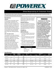
A2-MAN-ALM-ENG .... Alert-2 <strong>alarm</strong> manual English<br />
A2P-ANNU-CB ........... Annunciator circuit board assembly<br />
A2P-ANNU-E ............. Annunciator module English Alert-2<br />
A2P-ANNU-F .............. Annunciator module French Alert-2<br />
A2P-POWER-V2 ........ Power supply module Alert-2<br />
A2P-AREA-E-AIR ....... Area <strong>alarm</strong> module ISO-AIR Eng. Alert-2<br />
A2P-AREA-E-CO2 ..... Area <strong>alarm</strong> module ISO-CO2 Eng. Alert-2<br />
A2P-AREA-E-EVA ..... Area <strong>alarm</strong> module ISO-EVA Eng. Alert-2<br />
A2P-AREA-E-N2O ..... Area <strong>alarm</strong> module ISO-N2O Eng. Alert-2<br />
A2P-AREA-E-NIT ....... Area <strong>alarm</strong> module ISO-NIT Eng. Alert-2<br />
A2P-AREA-E-OXY ..... Area <strong>alarm</strong> module ISO-OXY Eng. Alert-2<br />
A2P-AREA-E-VAC ..... Area <strong>alarm</strong> module ISO-VAC Eng. Alert-2<br />
A2P-AREA-U-AIR ...... Area <strong>alarm</strong> module USA - AIR Alert-2<br />
A2P-AREA-U-OXY ..... Area <strong>alarm</strong> module USA - OXY Alert-2<br />
A2P-AREA-U-VAC ..... Area <strong>alarm</strong> module USA - VAC Alert-2<br />
A2P-AREA-CB-AIR .... Area circuit board assembly - AIR<br />
A2P-AREA-CB-CO2 ... Area circuit board assembly - CO2<br />
A2P-AREA-CB-EVA ... Area circuit board assembly - EVA<br />
A2P-AREA-CB-N2O ... Area circuit board assembly - N2O<br />
A2P-AREA-CB-NIT .... Area circuit board assembly - NIT<br />
A2P-AREA-CB-OXY .. Area circuit board assembly - OXY<br />
A2P-AREA-CB-VAC ... Area circuit board assembly - VAC<br />
A2P-SENS-E-AIR ....... Sensor module ISO-AIR Eng. Alert-2<br />
A2P-SENS-E-CO2 ..... Sensor module ISO-CO2 Eng. Alert-2<br />
A2P-SENS-E-EVA ..... Sensor module ISO-EVA Eng. Alert-2<br />
A2P-SENS-E-N2O ..... Sensor module ISO-N2O Eng. Alert-2<br />
A2P-SENS-E-NIT ....... Sensor module ISO-NIT Eng. Alert-2<br />
A2P-SENS-E-OXY ..... Sensor module ISO-OXY Eng. Alert-2<br />
A2P-SENS-E-VAC ..... Sensor module ISO-VAC Eng. Alert-2<br />
A2P-SENS-U-AIR ...... Sensor module USA-AIR Eng. Alert-2<br />
A2P-SENS-U-OXY ..... Sensor module USA-OXY Eng. Alert-2<br />
A2P-SENS-U-VAC ..... Sensor module USA-VAC Eng. Alert-2
Model Number Description<br />
Alert - 2 Series<br />
A2P-MAST-E-AME ..... Master <strong>alarm</strong> module - English 10 points<br />
A2P-MAST-E-ISO ...... Master <strong>alarm</strong> module - ISO English10 points<br />
A2P-MAST-F-AME ..... Master <strong>alarm</strong> module - French 10 points<br />
A2P-MAST-CB ........... Master circuit board Assembly Alert-2<br />
A2P-MAST-CB-ISO .... Master circuit board Assembly ISO Alert-2<br />
A2P-BLANK ............... Alert-2 <strong>alarm</strong> module blank (filler)<br />
A2P-BOXASS-4 ......... Alarm back box Assembly 4-station Alert-2<br />
A2P-BOXASS-7 ......... Alarm back box Assembly 7-station Alert-2<br />
A2P-COMP-10 ........... Computer interface Module English 10-pts.<br />
A2P-FRMASS-4 ......... Alarm frame assembly 4-station Alert-2<br />
A2P-FRMASS-7 ......... Alarm frame assembly 7-station Alert-2<br />
A2P-PIPE ................... Pressure module pipe assembly (Alert-2)<br />
A2P-RIBBON-4 .......... Ribbon cable assembly 4-station Alarm<br />
A2P-RIBBON-7 .......... Ribbon cable assembly 7-station Alarm<br />
Page: 29
Amico Microprocessor Based Alarm<br />
Page: 30<br />
DIMENSIONS<br />
Area Alarm
DIMENSIONS<br />
Master Alarm<br />
Alert - 2 Series<br />
Page: 31
Amico Microprocessor Based Alarm<br />
Page: 32<br />
APPENDIX - A<br />
Wiring Diagram - Auto-Switching<br />
Power Supply<br />
'& 3 &<br />
&<br />
$<br />
0<br />
$& 6<br />
9 9
$<br />
0<br />
APPENDIX - B<br />
Wiring Diagram - Annunciator<br />
K1<br />
U2 U5<br />
SILENCE TEST<br />
U4<br />
ISO NORM<br />
U3<br />
2 $ $<br />
NO NC COM GND +12V<br />
J1<br />
CH +1<br />
CH -<br />
NO NC COM GND +12V<br />
U1<br />
+<br />
-<br />
7 $<br />
0 0<br />
% 0 6<br />
2<br />
7 $<br />
5<br />
9'&<br />
'& 3<br />
3 6<br />
127(<br />
5<br />
5<br />
9<br />
9<br />
Alert - 2 Series<br />
Page: 33
Amico Microprocessor Based Alarm<br />
Page: 34<br />
APPENDIX - C<br />
Wiring Diagram - Area Display Module - Local Sensor
APPENDIX - D<br />
Alert - 2 Series<br />
Wiring Diagram - Area Display Module - Remote Sensor<br />
Note:<br />
For multiple sensors a<br />
multi-conductor twisted<br />
pair cable can be used.<br />
Page: 35
Amico Microprocessor Based Alarm<br />
Page: 36<br />
APPENDIX - E<br />
Wiring Diagram - Area Module to Master Module
APPENDIX - F<br />
Wiring Diagram - Abnormal Condition<br />
Alert - 2 Series<br />
Page: 37
Amico Microprocessor Based Alarm<br />
Page: 38<br />
APPENDIX - G<br />
Wiring Diagram - Area Slave
APPENDIX - H<br />
Wiring Diagram - Master Module<br />
Alert - 2 Series<br />
' &<br />
1 9<br />
Page: 39
Amico Microprocessor Based Alarm<br />
Page: 40<br />
APPENDIX - I<br />
Diagram - Computer Interface Module<br />
'<br />
% 0 6<br />
& &<br />
1& $<br />
5<br />
9'& $<br />
0<br />
0<br />
&<br />
,<br />
0<br />
CH 10C<br />
H 9C<br />
H 8C<br />
H 7C<br />
H 6C<br />
H 5C<br />
H 4C<br />
H 3C<br />
H 2C<br />
H 1<br />
U2<br />
U 4<br />
U1 U2<br />
U 4<br />
U 3<br />
CH 10C<br />
H 9C<br />
H 8C<br />
H 7C<br />
H 6C<br />
H 5C<br />
H 4C<br />
H 3C<br />
H 2C<br />
H 1<br />
+ + + + + + + + + +<br />
1<br />
2<br />
3<br />
4<br />
O N<br />
S 1
APPENDIX - J<br />
Wiring Diagram - Master to Slave Module<br />
Alert - 2 Series<br />
Page: 41
Amico Microprocessor Based Alarm<br />
Page: 42<br />
APPENDIX - K<br />
Technical Specification<br />
Supply Voltage: 90 to 240VAC - 50 to 60 Hz<br />
Current Draw: 1 Amp.Max.<br />
Fuse (1/4 * 1-1/4): Fast Blow 1 Amp.<br />
Cable requirement:<br />
Area Display Module to Remote Sensor:<br />
Distance: Maximum 5,000 feet [1,500 m]<br />
Cable: Belden # 8451 or equivalent.<br />
#22 gauge shielded, twisted pair. (For multiple<br />
sensors a multi-conductor twisted pair cable can be<br />
used).<br />
Signal: 13 VDC, 75 mA Maximum.<br />
Master Module to Source equipment:<br />
Distance: Maximum 10,000 feet [3,000 m]<br />
Cable: Minimum #22 gauge wire (does not have to be<br />
shielded, twisted pair).<br />
Signal: 5 VDC, < 5 µA.<br />
Computer Interface Board:<br />
Output: Dry Contacts NC, open on Alarm.<br />
Rating: 24 VDC - 0.1 Amps.
Amico Corporation<br />
21-121 Granton Drive, Richmond Hill, Ontario, L4B 3N4, Canada<br />
Tel.(905) 764-0800, Fax.(905) 764-0862Web Site: http://www.amico.com