You also want an ePaper? Increase the reach of your titles
YUMPU automatically turns print PDFs into web optimized ePapers that Google loves.
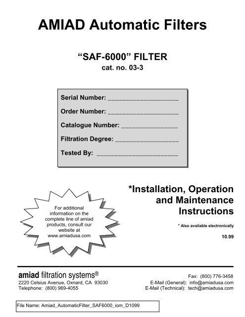
<strong>AMIAD</strong> <strong>Automatic</strong> <strong>Filters</strong><br />
<strong>“SAF</strong>-<strong>6000”</strong> FILTER<br />
cat. no. 03-3<br />
Serial Number: ____________________<br />
Order Number: ____________________<br />
Catalogue Number: ________________<br />
Filtration Degree: __________________<br />
Tested By: _______________________<br />
For additional<br />
information on the<br />
complete line of amiad<br />
products, consult our<br />
website at<br />
www.amiadusa.com<br />
*Installation, Operation<br />
and Maintenance<br />
Instructions<br />
* Also available electronically<br />
10.99<br />
amiad filtration systems ® Fax: (800) 776-3458<br />
2220 Celsius Avenue, Oxnard, CA 93030 E-Mail (General): info@amiadusa.com<br />
Telephone: (800) 969-4055 E-Mail (Technical): tech@amiadusa.com
TABLE OF CONTENTS<br />
Technical specifications ....................................................................................3<br />
Safety instructions ...........................................................................................4<br />
Dimensional and recommended installation drawing .........................................5<br />
Description and filter operation...................................................................... 6-7<br />
Installation ........................................................................................................8<br />
Maintenance.....................................................................................................9<br />
Disassembling and reassembling............................................................ 10 - 11<br />
Parts schedule ................................................................................................12<br />
Parts drawing Section 1 ...............................................................................13<br />
Parts drawing - Section 2................................................................................14<br />
Parts drawing - Section 3................................................................................15<br />
Appendix A "PLC" Control system, Type "D" ........................................ 16 - 21<br />
Appendix B "RELAY" Control system, Type "C".................................... 22 - 26<br />
With any inquiry please quote Filter Serial Number, located on the filter housing.<br />
2<br />
amiad filtration systems
TECHNICAL SPECIFICATIONS<br />
General<br />
Maximum flow rate 400 m 3 /h 1760 USgpm<br />
3<br />
Consult manufacturer for optimum flow<br />
depending on filtration degree & water quality.<br />
Min. working pressure 2.0 bar 30 psi or lower if pressure is increased for flushing<br />
Max. working pressure 10 bar 150 psi 16 bar = 240 psi upon request<br />
Filter area 6000 cm 2 930 in 2<br />
Inlet/Outlet diameter 150, 200, 250 mm Flange standards as per request.<br />
Filter housing 350 mm 14" Epoxy-coated steel, or other on request.<br />
Max. working temperature 80 0 C 176 0 F<br />
Weight 150 mm = 240 Kg 6" = 528 lb.<br />
Flushing Data<br />
200 mm = 245 Kg 8" = 340 lb.<br />
250 mm = 260 Kg 10" = 572 lb.<br />
Exhaust valve 50 mm 2"<br />
Flushing cycle time 40 seconds 40 seconds<br />
Wasted water per cycle 280 liter 74 gallon at 2 bar = 30 psi<br />
Minimum flow for flushing 25 m 3 /h 110 USgpm at 2 bar = 30 psi<br />
Control and Electricity<br />
Control voltage 24V AC (12V or 24V DC upon request)<br />
Electric motor 1/3 HP 50 / 60 Hz, 25 / 30 Gear output R.P.M.<br />
Rated operation Voltage 3 phase<br />
Single phase<br />
DC<br />
220 / 380 / 440 V, 50 / 60 Hz<br />
110 / 220 V, 50 / 60 Hz<br />
12V or 24V (upon request)<br />
Current consumption 0.8 Amp. (with 3 phase 380 / 440 V)<br />
Construction Materials<br />
Filter Housing and Lid Epoxy-coated carbon steel 37-2 (Stainless Steel 316 available on request).<br />
Screens Stainless Steel 316<br />
Cleaning mechanism Stainless Steel 316, POM<br />
Exhaust valve Epoxy-coated cast iron, Natural Rubber<br />
Seals Synthetic Rubber, Teflon<br />
Control Aluminum, Brass, Stainless Steel, PVC<br />
Standard Filtration Degrees<br />
Stainless Steel Weavewire Screen<br />
micron 500 300 200 130 100 80 50 25 10<br />
mm 0.5 0.3 0.2 0.13 0.1 0.08 0.05 0.02 0.01<br />
mesh 30 50 75 120 155 200 300 450 600<br />
amiad filtration systems
SAFETY INSTRUCTIONS<br />
General<br />
1. Prior to installation or any treatment given to the filter, read carefully the installation and operation instructions.<br />
2. While treating the filter all conventional safety instructions should be observed in order to avoid danger to the<br />
workers, the public or to property in the vicinity.<br />
3. Please note, the filters enters into a flushing mode automatically, without prior warning.<br />
4. No changes or modification to the equipment are permitted without a written notification given by the manufacturer<br />
or by its representative, on the manufacturer behalf.<br />
Installation<br />
1. Install the filter according to the installation instructions detailed in this manual.<br />
2. Make sure to leave enough clearance so as to enable easy access for future treatments and safe maintenance<br />
operations.<br />
3. Electric wiring should be performed by an authorized electrician only, using standardized and approved<br />
components.<br />
4. Install main power disconnect cut-off switch close to the control panel.<br />
5. If the control panel is installed far away and there is no eye contact with the filter, a power disconnect cut-off switch<br />
should be installed near each filter unit.<br />
6. Installation of the filter should be performed so as to avoid direct water splashing on the electrical components or<br />
on the control panel.<br />
7. Extra safety devices should be installed on hot water applications to avoid skin burn danger.<br />
Operation, Control and Maintenance<br />
1. Disconnect the filter from power supply before maintenance or treatment.<br />
2. Loosening or unscrewing bolts should be done only after the pressure in the filter had been released.<br />
3. Avoid splashing and water leaking so as to minimize slipping electrifying danger or damage to the equipment<br />
caused by moisture.<br />
4. Always open and close valves slowly and gradually.<br />
5. Remove grease and fat material residues in order to avoid slipping.<br />
6. After treatment has been completed, re-assemble the protection covers of the drive mechanism.<br />
7. Manual cleaning of filter element using high water pressure or steam, should be performed in accordance with the<br />
cleaning system instructions and without endangering the operator or his vicinity.<br />
8. Manual cleaning of filter element using acid or other chemical agents, should be performed in accordance with the<br />
relevant material safety instructions and without endangering the operator or his vicinity.<br />
Use of Lifting Equipment<br />
1. While using lifting equipment, make sure that the filter or the lifted part is chained securely and in a safe manner.<br />
2. Do not leave lifted equipment if there is no necessity. Avoid working below lifted equipment.<br />
3. Ware a safety helmet while using lifting equipment.<br />
4<br />
amiad filtration systems
DIMENSIONAL DRAWING AND RECOMMENDED INSTALLATION<br />
Key:<br />
Dimensions in mm (inches)<br />
1. 8" SAF-6000<br />
2. 8" inlet butterfly valve<br />
3. 8" by-pass valve (option)<br />
4. 8" downstream valve (recommended)<br />
5. 8" non-return check valve (recommended)<br />
* Minimum distance required for maintenance.<br />
5<br />
amiad filtration systems
DESCRIPTION OF FILTER OPERATION<br />
Filtering process:<br />
The SAF-6000 is a sophisticated yet easy-to-operate automatic filter, with a self -cleaning mechanism driven by an electric motor.<br />
The SAF-6000 is designed to work with various types of screens in filtration degrees from 500 to 10 micron, and is available in 6",8"<br />
and 10" inlet/outlet diameter.<br />
The water enters through the inlet pipe into the coarse screen from outside in, and through the fine screen from inside out. The<br />
"filtration cake" accumulates on the fine screen surface and causes head loss to develop.<br />
The coarse screen is designed to protect the cleaning mechanism from large dirt particles. It should not accumulate large quantities<br />
of suspended solids and is not cleaned automatically.<br />
Self-cleaning process:<br />
The SAF-6000 will start the self -cleaning process when the pressure differential across the screen reaches a pre-set value or a<br />
predetermined lapse of time.<br />
Cleaning of the filter element is carried out by the suction scanner which rotates in a spiral movement while removing the filtration<br />
cake from the screen and expels it out through the exhaust valve.<br />
The rotation of the scanner is operated by a 2-way (fwd/rev) drive unit that is attached to the scanner by a threaded shaft which<br />
provides the linear movement.<br />
The exhaust valve is activated for the duration of the cleaning cycle by a 3-way solenoid. During the self-cleaning process, which<br />
takes approximately 35 seconds, filtered water continues to flow downstream.<br />
Different modes of filtration:<br />
The filtration system may be found in one of the following modes:<br />
1. Filtering mode: This is the normal function condition. Flushing is not occurring and the power light on the control board is lit.<br />
2. Flushing mode: A mode in which the flushing process is in progress. The motor and exhaust valve are operating according to<br />
the program.<br />
3. Continuous flushing mode: It is possible to activate the self-cleaning mechanism continuously by changing the switch near the<br />
timer in the control board to "CONT." position.<br />
4. Malfunction mode: During malfunction mode the self-cleaning operation is stopped, the malfunction light on the control board is<br />
turned on and an external output is activated with 24V AC.<br />
6<br />
amiad filtration systems
The filtration system may enter a malfunction mode in the following cases:<br />
1. When there is a continuous signal from the pressure differential switch for a duration of more than the pre-set time. This means<br />
that the self-cleaning process is not successful.<br />
2. When the motor protector was activated, either manually or due to over load.<br />
3. A malfunction in the limit switches.<br />
Initiation of self-cleaning:<br />
The filter will enter the self-cleaning process as a result of any of the following causes:<br />
1. A signal from the Pressure Differential Switch (PDS) - The PDS which is situated on the filter body, sends an electric signal<br />
when the pressure differential across the screen reaches the pre-set value (usually 0.5 bar =7 psi). The control board registers<br />
the signal and operates the flushing process according to its program.<br />
2. Manually pressing the "TEST" push button at the control board.<br />
3. The TIMER installed in the control board allows operation of self-cleaning process at time intervals that can be set up,<br />
independent from the head loss factor. The timer resets after every flushing cycle.<br />
4. A signal from Continual flushing switch - This switch in the control board allows operation in continuous flushing mode; meaning,<br />
the filter is flushing itself all the time regardless of flow rate or water quality.<br />
Control system:<br />
Two types of control boards are available: PLC Type and Relay Type. See Appendix A or B for details.<br />
7<br />
amiad filtration systems
INSTALLATION<br />
Design recommendations:<br />
1. If flow increases and pressure drops dramatically for a long period of time during network filling -up, it is recommended that a<br />
pressure sustaining valve is installed downstream. The pressure sustaining valve will ensure a controlled filling-up of the line.<br />
2. If continual water flow is essential even during maintenance period, it is recommended that a manual or automatic by-pass is<br />
installed, and the isolating valves will be used to isolate each filter unit.<br />
3. In places where there is an expected temporary worsening of water quality, it is possible to operate an emergency flushing<br />
program. In order to do so, a hydraulic controlled valve has to be installed downstream. For details, please consult the<br />
manufacturer.<br />
Installation instructions:<br />
1. Install the filter horizontally in a way which will allow convenient approach and enough space to dismantle the filter for<br />
maintenance purposes.<br />
2. Ensure the direction of flow according to the arrows marked on the filter housing.<br />
3. It is recommended to install a mechanical non-return valve downstream of the filter.<br />
4. Connect a minimum of 2" pipe to the exhaust valve. The exhaust pipe should be designed so that it creates minimal resistance<br />
to flow of 25 m3/h (110 USgpm).<br />
5. If the system is designed to operate with working pressure higher than 6 bar (85 psi), it is recommended that a manual valve is<br />
installed on the exhaust pipe, in order to enable regulation of the flushing flow rate.<br />
6. The user should arrange suitable lighting at the area of the filter to enable good visibility and safe maintenance.<br />
7. The user should arrange suitable platforms and safety barriers to enable easy access to the filter without climbing on pipes and<br />
other equipment.<br />
IMPORTANT !!<br />
• Prevent static back pressure or reverse flow through the filter.<br />
• Install a manual or a hydraulic valve downstream of the filter.<br />
Electric wiring:<br />
1. Install the control board in a dry and protected place (It is possible to order a special control board for out-door installation).<br />
2. Power connection to the control board:<br />
a. Connect a three-phase voltage source through a semi-automatic switch, or 16 Amp. fuse to the L1 L2 L3 inlet at the<br />
terminal strip in the control board.<br />
b. Earth the control board.<br />
3. Power connection to the motor: Connect the drive unit to the control panel by means of a 4 x 2.5mm (12 or 14 AWG) wire in<br />
flex-conduct. Use a long enough cable to allow removal of the drive unit and placing it near the filter for maintenance, without<br />
having to disconnect it from the cable. (It is recommended that this installation meets or exceeds local or national electrical<br />
codes, this is a "high" voltage connection).<br />
4. Control wiring: Connect between the control junction box and the control board by means of 6 x 1.5 mm 2 (16 AWG) wire in flexconduct.<br />
The numbers on the terminals in the board and in the junction box are identical.<br />
Start-up and first operation<br />
1. Make sure all the electric wiring is correct, according to the drawings supplied with the control board itself. The electrical<br />
drawings in this manual are for reference only.<br />
2. Switch the control & 24V circuit breakers and the motor protector to ON. The motor will start operating*.<br />
The suction scanner shaft should turn clockwise and move towards the filter housing until it reaches limit switch "A". If the motor<br />
rotates in the opposite direction, disconnect the electricity immediately and change the direction of the motor rotation by<br />
changing between two phases.<br />
The motor must stop when the magnetic disc reaches limit switch "A" and causes it to operate.<br />
3. Operate a "dry" flushing cycle by pressing on the "TEST" push button. Make sure all flushing stages occur as described in the<br />
filter description chapter of this manual.<br />
4. Open the inlet valve to the filter, while the outlet valve remains closed or with an open by-pass valve (This will keep the flow in<br />
the filter at a minimum), and operate a flushing cycle.<br />
Make sure the exhaust valve opens and all stages of the flushing cycle are carried out. Attend to leakages, if any.<br />
Close the 1/4" valve at the low pressure point of the pressure differential switch for 5 seconds. The PDS hand will move to the<br />
red area and the filter will start the flushing process. Open the 1/4" valve.<br />
5. Gradually open the outlet valve and/or close the by-pass valve. Operate the filter at the designed hydraulic conditions.<br />
6. Set the timer for 6-8 hours.<br />
7. Check and re-tight all bolts after the first week of operation.<br />
* When using Control board type "C" (Relay type) it is necessary to press the "Test" push button in order to start the motor<br />
operation for the first time.<br />
8<br />
amiad filtration systems
MAINTENANCE<br />
General inspection<br />
In order to check the proper operation of the filter, close the low pressure 1/4" valve to the pressure differential switch for a period of<br />
5 seconds. This will initiate the self-cleaning cycle: Check that the exhaust valve opens, that the scanner moves forwards, and<br />
when it reaches limit switch "B" - verify that the exhaust valve closes.<br />
Weekly maintenance<br />
1. Check that the filter operates properly, following a general inspection.<br />
2. Clean the 3/4" filter (close the 3/4" valve and operate a flushing cycle in order to release pressure and then open the bowl).<br />
3. Check that there is grease on the drive shaft, and drive bushing. Add grease if necessary.<br />
4. Take care of any leakage from the scanner shaft. If necessary, tighten the sealing nut (32) or replace the sealing nut internal Oring<br />
(32.1)<br />
Changing the sealing nut internal O-ring:<br />
1. Close the inlet valve to the filter and release the pressure.<br />
2. If the Suction Scanner is in the outer position, operate a flushing cycle and bring it to the inner position.<br />
3. Remove the Split pin (34) and pull out the connecting pin (33).<br />
4. Operate a flushing cycle.<br />
5. Stop the motor operation when the drive shaft reaches half way of its movement. The drive shaft is now separated from the<br />
Suction Scanner.<br />
6. Unscrew the sealing nut (32).<br />
7. Remove the used internal O-ring and clean the O-ring seat.<br />
8. Insert a new O-ring (32.1)<br />
9. Tighten the sealing nut (32).<br />
10. Re-connect the drive shaft to the suction scanner shaft.<br />
11. Operate the control board and open the filter inlet valve.<br />
Maintenance prior to long term cessation of filter operation<br />
The following must be done if the filter will not operate for more than a month.<br />
1. Operate flushing cycle (If possible, with a closed downstream valve).<br />
2. Disconnect the control board from the power.<br />
3. Release pressure from the filter.<br />
4. Grease the drive shaft and the drive bushing.<br />
5. Clean the 3/4" control filter.<br />
6. Clean the coarse screen through the service port.<br />
Maintenance prior to re-operation<br />
1. Connect the control board to the mains.<br />
2. Check proper operation of the filter.<br />
3. Grease the drive shaft and the drive bushing.<br />
4. If necessary change the sealing nut internal O-ring.<br />
IMPORTANT !!<br />
THE DRIVE SHAFT MUST BE LUBRICATED WITH HEAVY-DUTY, WATER RESISTANT GREASE, THAT WILL NOT OXIDIZE.<br />
(SHELL, DARINA EP-2 OR SIMILAR).<br />
Cleaning the coarse screen:<br />
1. Close the filter inlet valve.<br />
2. Release pressure from the filter by<br />
operating a flushing cycle.<br />
3. Remove the service lid (47) by<br />
disconnecting the bolts (48) from the nuts<br />
(48.3)<br />
4. Clean the coarse screen:<br />
To remove large particles, insert your<br />
hand into the coarse screen area.<br />
To remove fine particles and organic<br />
matter, rinse the screen. Afterwards,<br />
partially open the inlet valve and let water<br />
flow out.<br />
9<br />
amiad filtration systems
DISMANTLING AND ASSEMBLING THE FILTER COMPONENTS<br />
Prior to opening the filter it is recommended to operate a flushing cycle by pressing<br />
FINE SCREEN<br />
Dismantling:<br />
1. Close the filter inlet and outlet valves and release the pressure.<br />
2. Press the "TEST" push button and disconnect the power when the scanner is in the middle of its track (When the limit switch<br />
disc is half-way between the two limit switches).<br />
3. Release the lid bolts (7) from their nuts.<br />
4. Locate the centering sleeves (8), remove them from their holes and remove the lid (5).<br />
5. Remove the seal (10) from the screen (11) and pull it out of the filter housing.<br />
6. Remove the second seal from the screen.<br />
Assembly:<br />
1. Put the screen seal (10) on one end of the<br />
screen (11).<br />
2. Insert the screen (11) into the filter<br />
housing (14). Make sure the screen is<br />
correctly positioned, all the way in.<br />
3. Put the second seal (10) on the other end<br />
of the screen.<br />
4. Assemble the lid on the filter housing.<br />
Make sure the screen and seal are<br />
correctly positioned in the lid seating.<br />
5. Insert the centering sleeves (8) into two<br />
opposite holes in the lid flange.<br />
6. Insert bolts (7) with the discs on the lid<br />
side.<br />
7. Place the discs and the nuts on bolts (7)<br />
on the housing side. Do not tighten them<br />
yet.<br />
8. Tighten the bolts (7) in a controlled and<br />
balanced method.<br />
9. Open the filter inlet and outlet valves and<br />
operate the control board.<br />
10. Check proper operation of the filter.<br />
SUCTION SCANNER<br />
Dismantling:<br />
1. Begin the dismantling procedure as per 1-4 in the chapter<br />
"dismantling the fine screen".<br />
2. Partially release the tightening nut (32).<br />
3. Pull out the drive shaft connecting pin (33) by first removing the split<br />
pin (34).<br />
4. Pull the suction scanner (9) in a spiral movement out of the filter<br />
housing.<br />
Assembly:<br />
1. Insert the suction scanner (9) into the screen (11). Make sure that<br />
the scanner shaft (9.3) passes through the tightening nut (32).<br />
2. Insert the suction shaft (9.3) into the drive shaft (35). Make sure the<br />
holes in the above shafts are parallel.<br />
3. Insert the connecting pin (33) to the parallel hole of the suction shaft<br />
(9.3) and the drive shaft (35) and lock it with the split pin (34).<br />
4. Put the screen seal (10) on the end of the screen.<br />
5. Continue to assemble the parts as per 4-10 in the chapter<br />
"Assembling the fine screen".<br />
10<br />
9.3 9<br />
amiad filtration systems
DRIVE SHAFT HOUSING AND COARSE SCREEN<br />
Dismantling:<br />
1. Close the inlet and outlet valves of the filter<br />
and release pressure.<br />
2. Disconnect power supply from the control<br />
board.<br />
3. Remove the cover from the drive shaft<br />
housing (45) by unscrewing the wing nuts<br />
(53.5). Pull out the plug from the solenoid<br />
coil, remove the limit switch sling (50) from<br />
the drive shaft housing by unscrewing the<br />
bolts (51).<br />
4. Carefully put the limit switch sling near the<br />
filter to avoid any damage to the electrical<br />
wires.<br />
5. Disconnect the pilot tube (40.3) from the<br />
solenoid valve (41) and connector (40.2).<br />
6. Disconnect the drain pipe from the exhaust<br />
valve.<br />
7. Remove the drive unit (37) from the drive<br />
shaft housing (24) by unscrewing the nuts<br />
(26.4) from the bolts (26). By doing so the<br />
drive shaft key (36) will be pulled out.<br />
8. Pull out the connecting pin (33) by first<br />
removing the split pin (34).<br />
9. Turn the drive shaft (35) using a suitable<br />
spanner in order to release it from the<br />
scanner shaft (9.3).<br />
10. Partially release the tightening nut (32).<br />
11. Dismantle the drive shaft housing (24) from<br />
the filter housing (14) by unscrewing the<br />
bolts (25).<br />
12. Pull out the flushing chamber (19) and the<br />
coarse screen (18).<br />
Assembly:<br />
1. Insert the coarse screen (18) into its place in the filter housing.<br />
2. Apply some grease on the O-ring (22) and insert the flushing chamber into its place. Make sure the scanner pipe enters into its<br />
bearing (23).<br />
3. Install the drive shaft housing (24) into the filter housing (14) with the bolts (25) and tighten them.<br />
4. Connect the drive shaft (35) to the scanner shaft by using the connecting pin (33) and split pin (34).<br />
5. Make sure that the drive shaft key (36) is fitted properly in the gear box. Thread the drive shaft through the drive unit and note<br />
that the drive shaft groove is adjusted in accordance with the drive shaft key.<br />
6. Connect the drive unit (37) to the drive shaft housing (24) with the bolts (26) and tighten them.<br />
7. Connect the pilot tube between the solenoid valve (41) and the connector (40.2).<br />
8. Assemble the limit switch sling in its place and push in the plug of the solenoid coil.<br />
9. Connect the drain pipe to the exhaust valve (42).<br />
10. Operate the control board and make sure the filter is operating properly.<br />
11. Open the inlet and outlet valves and recheck filter operation.<br />
11<br />
amiad filtration systems
PARTS SCHEDULE<br />
Refer to drawing on pages 14 & 15<br />
No. Description Cat. No.<br />
1 Tightening plug - leading shaft 53-3074-1022<br />
2 Tightening plug - seal 81-41-4000-0128<br />
3 leading shaft 53-3074-1032<br />
4 Upper bearing insert 53-3074-1026<br />
5 Housing lid 13-3077-1100<br />
7 Bolt M20 x 80 (x12) 85-1112-20-080<br />
7.1 Washer M20 (x12) 85-1311-12-000<br />
7.2 Washer M20 (x12) 85-1311-12-000<br />
7.3 Nut M20 (x12) 85-1212-20-000<br />
8 Centering sleeve (x 2) 63-3074-0011<br />
9 Suction scanner 13-3074-5000<br />
9.1 Lower bearing insert 53-3074-0141<br />
9.2 Scanner nozzle (x 4) 53-3074-0132<br />
9.3 Suction scanner shaft 53-3074-7143<br />
9.4 Slotted Spring pin 5 X 50 84-32-10-0011<br />
9.5 Slotted Spring pin 3 X 30 84-32-10-0018<br />
10 Screen seal (x 2) 81-41-4300-0201<br />
11 Fine screen 81-13-1000-0XXX *<br />
12 Lid seal 81-41-4000-0459<br />
13 Three-Way Valve 63-1073-1006<br />
13.1 L-Connector 5/16" x 1/4" 82-13-0692-0504<br />
13.2 1/4" Brass Bushing 82-13-1204-0404<br />
13.3 L-Connector 5/16" x 1/4" 82-13-0692-0504<br />
13.4 Pressure Gauge 84-40-00-0001<br />
13.5 L-Connector 1/4"M X 1/4"F 82-12-0125=0404<br />
13.6 Copper Tube 5/16" 82-13-0000-0050<br />
13.7 L-Connector 5/16" x 1/4" 82-13-0692-0504<br />
14 Filter housing 13-3XX7-11XX *<br />
15 Electrical junction box 13-3074-6000<br />
15.1 Bolt M5 x 16 (x 4) 85-2142-05-016<br />
15.2 Nut M5 (x 4) 85-2212-05-000<br />
15.3 Washer M5 85-2312-05-000<br />
16 Pressure differential switch 84-31-10-0001 *<br />
16.1 Connector 5/16" x 1/8" 82-13-0682-0502<br />
16.2 Connector 5/16" x 1/8" 82-13-0682-0502<br />
16.3 L-Connector 5/16" x 1/4" 82-13-0692-0504<br />
16.4 Copper Tube 5/16" (H.P.) 82-13-0000-0050<br />
16.5 Copper Tube 5/16" (L.P.) 82-13-0000-0050<br />
16.6 L-Connector 5/16" x 1/4" 82-13-0692-0504<br />
16.7 Manometer valve 1/4" 82-32-9002-1000<br />
16.8 P.D.S enclosure 53-3074-1040<br />
16.9 Bolt M5 x 16 (x 2) 85-2142-05-016<br />
16.10 Washer M5 85-2312-05-000<br />
16.11 Nut M5 (x 2) 85-2212-05-000<br />
16.12 Cable Connector - PG-7 84-87-00-0007<br />
17 Drive shaft housing seal 81-41-4000-0448<br />
18 Coarse screen 53-3074-2020<br />
No. Description Cat. No.<br />
19 Flushing chamber 13-3074-7010<br />
20 Bolt M10 x 30 (x2) 85-2112-10-030<br />
20.1 St. St. washer M10 (x 2) 85-2312-10-000<br />
22 Sealing flange O-ring 81-41-4100-0460<br />
23 Sealing flange 63-3074-7024<br />
24 Drive shaft housing 53-3074-0010<br />
25 Bolt M16 x 70 (x 8) 85-1112-16-070<br />
25.1 Washer M16 (x 8) 85-1311-16-000<br />
25.2 Washer M16 (x 8) 85-1311-16-000<br />
25.3 Nut M 16 (x 8) 85-1212-16-000<br />
26 Bolt M8 x 40 (x4) 85-1112-08-040<br />
26.1 Washer M8 (x4) 85-1312-08-000<br />
* Catalog number might differ according to filter diameter, flange standard or electric specifications.<br />
12<br />
No. Description Cat. No.<br />
26.2 Washer M8 (x4) 85-1312-08-000<br />
26.3 Spring washer M8 (x4) 85-1321-05-000<br />
26.4 Nut M8 85-1212-08-000<br />
27 Magnetic disc Locking Ring 84-32-10-0102<br />
28 Magnetic disc 84-32-10-0101<br />
29 St.St. Bolt M6 X 35 (X3) 85-2112-06-035<br />
29.1 St.St. Washer M6 (X3) 85-2312-06-000<br />
29.2 St.St. Washer M6 (X3) 85-2312-06-000<br />
29.3 St.St. Lock nut M6 (X3) 85-2232-06-000<br />
30 Drive bushing 53-3074-1021<br />
31 Sealing rope set- scanner shaft 53-3074-1051<br />
32 Sealing rope tightening nut 53-3074-7033<br />
32.1 Sealing Nut Internal O-Ring 81-41-4100-0020<br />
33 connecting pin 53-3074-0142<br />
34 Split pin 63-0403-0003<br />
35 Drive shaft 53-3074-7031<br />
36 Drive shaft key 53-3074-1025<br />
37 Drive unit (motor and gear) 53-3074-3500<br />
38 3/4" Angle 83-3225-0073-0000<br />
39 3/4" Ball valve 82-32-0007-1000<br />
40 3/4" Control filter 0.2 mm 01-0702-1131-8020<br />
40.1 Raccord connector 3/4" x 1/4" 53-0500-901<br />
40.2 L-Connector 5/16" x 1/4" 82-13-0692-0504<br />
40.3 Copper tube 5/16" 82-13-0000-0050<br />
41 Solenoid valve 82-21-0024-0001 *<br />
41.1 L-Connector 5/16" x 1/8" 82-13-0692-0502<br />
41.2 L-Connector 5/16" x 1/4" 82-13-0692-0504<br />
41.3 connector 1/4" x 1/4" 52-0100-002<br />
42 2" Exhaust valve 82-31-0023-0000<br />
42.1 connector 5/16" x 1/4" 82-13-0682-0504<br />
42.2 Copper tube 5/16" (drain) 82-13-0000-0050<br />
45 Drive shaft housing cover 13-3074-1120<br />
47 6" Blind flange 83-0116-0600-0001<br />
47.1 6" Seal 81-41-4000-0443<br />
48 Bolt M16 x 60 (x 8) 85-1112-16-060<br />
48.1 Washer M16 (x 8) 85-1311-16-000<br />
48.2 Washer M16 (x 8) 85-1311-16-000<br />
48.3 Nut M 16 (x 8) 85-1212-16-000<br />
49 Magnetic limit switch (x 2) 84-32-10-0103<br />
50 Limit switch sling 53-3074-7021<br />
51 St.St. Bolt M6 X 15 (X 2) 85-2112-06-015<br />
51.1 St.St. Washer M6 (X2) 85-2312-06-000<br />
51.2 St.St. Washer M6 (X2) 85-2312-06-000<br />
51.3 St.St. Lock nut M6 (X2) 85-2232-06-000<br />
52 St.St. Bolt M3 X 10 (X 4) 85-2112-03-010<br />
52.1 St.St. Washer M3 (X8) 85-2312-03-000<br />
52.2 St.St. Lock nut M3 (X4) 85-2232-03-000<br />
52.3 Limit Switch Seat (X2) 63-2074-1015<br />
52.4 St.St. Bolt M6 X 15 (X 2) 85-2112-06-015<br />
52.5 St.St. Washer M6 (X2) 85-2312-06-000<br />
52.6 St.St. Lock nut M6 (X2) 85-2232-06-000<br />
53 Bolt M6 x 60 (x 2) 85-2112-06-060<br />
53.1 Washer M6 (x 2) 85-2312-06-000<br />
53.2 Washer M6 (x 2) 85-2312-06-000<br />
53.3 Nut M6 (x 2) 85-2212-06-000<br />
53.4 Washer M6 (x 2) 85-2312-06-000<br />
53.5 Wing nut (x 2 ) 85-2242-06-000<br />
54 Drive Shaft Cover 53-3074-0020 *<br />
54.1 Socket Set Screw M6X45 (X4) 85-2132-06-045<br />
amiad filtration systems
PARTS DRAWING Section 1<br />
13<br />
amiad filtration systems
PARTS DRAWING Section 2<br />
14<br />
amiad filtration systems
PARTS DRAWING Section 3<br />
15<br />
amiad filtration systems
APPENDIX A.<br />
"PLC" CONTROL SYSTEM (TYPE "D" SAF SERIES)<br />
Description of control panel components:<br />
1. Pilot lights:<br />
Yellow - lights ON when power is on.<br />
Red - lights ON when the control panels enters malfunction mode.<br />
2. Push buttons:<br />
TEST Manual operation of a flushing cycle.<br />
RESET - clears the malfunction mode.<br />
3. Flushing counter:<br />
Counts the flushing cycles that occurred. Used for follow-up on the system operation.<br />
4. Timer T1 (0-30 hours):<br />
Allows timed flushing cycles. The timer is reset with each flushing cycle.<br />
To cancel timed flushing, set selector SW1 to "PRESS. ONLY".<br />
Changing the switch to "CONT." will cause the filter to flush continuously regardless of pressure differential or<br />
time.<br />
5. Motor protector:<br />
This switch protects the motor in case of short-circuit or overload. It is important to set amperage according to the<br />
label of the motor. When this switch is tripped, the fault light will blink.<br />
6. Contactors CU and CD:<br />
Controls direction of motor rotation.<br />
7. Transformer:<br />
Electric supply to the various control components.<br />
8. 2 x 6 Amp. and 1 x 4 Amp. Circuit breakers:<br />
Short-circuit protection for the control system.<br />
9. PLC:<br />
A Programmable Logic Controller responsible for the control panel operation according to a preset program.<br />
Stages of cleaning cycle:<br />
1. The exhaust valve opens to atmosphere.<br />
2. Five seconds delay.<br />
3. The motor starts rotating the suction scanner shaft until it reaches limit switch "B" (T.L.S).<br />
4. The exhaust valve closes.<br />
The suction scanner remains at limit switch B until the next flushing cycle. In the next flushing cycle, it will move<br />
from L.S B to L.S "A" (B.L.S).<br />
In some versions of control panels, the suction scanner automatically returns to position "A" at the end of the<br />
flushing cycle. In this case the flushing cycle always begins from L.S. "A" (B.L.S).<br />
NOTE: The limit switches are wired as Normally Closed contacts (NC). Therefore, when the "Limit Switch Plate"<br />
reaches the limit switch, the contact opens and the PLC receives "NO SIGNAL".<br />
Requests for flushing cycle:<br />
a. PDS (Pressure Differential Switch)<br />
b. Timer 0-30 Hr.<br />
c. TEST button activation<br />
d. Continuous flushing<br />
16<br />
amiad filtration systems
PDS operation:<br />
The PDS constantly monitors the pressure differential between the inlet and outlet of the "SAF" filter.<br />
When the PDS senses a preset value (usually 0.5 bar=7 PSI) there is a delay of three (3) seconds before the flush<br />
cycle begins. At the end of the cleaning cycle, if the pressure differential signal remains, the filter will continue to<br />
clean itself for 15 minutes before entering into malfunction mode.<br />
Timer operation:<br />
Flush according to time is available through a built in timer. It is possible to preset the intervals between flush cycles,<br />
regardless of the pressure differential.<br />
The recommended default is between 6-8 hours.<br />
In order to cancel the timer operation, simply turn the timer selector SW1 to its middle position.<br />
"TEST" operation:<br />
The "TEST" button activates a manual self -cleaning cycle, in order to test the filter operation.<br />
Continuous flushing:<br />
The filter flushes continuously regardless of pressure differential or time. It is recommended that this mode be used<br />
for a limited duration only - in order to overcome extreme dirt load situations.<br />
Malfunction modes:<br />
The system recognizes two malfunction modes:<br />
1) Mechanical fault<br />
2) Clogging fault (DP Fault).<br />
Mechanical fault:<br />
Occurs under any of the following conditions:<br />
a. The over load motor protector is tripped.<br />
Find and correct the fault reason, clear the fault mode by pressing the O.L. motor protector to the ON position.<br />
b. Limit switch failure.<br />
The motor has been activated and there is no signal from a limit switch for more than 35 seconds. The problem<br />
might be with one of the limit switches or the drive mechanism. Find and correct the fault, clear the fault mode by<br />
pressing the RESET push-button.<br />
c. Both limit switches signal "OPEN" simultaneously.<br />
This may be a result of a limit switch failure, wrong wiring or wiring break off.<br />
Find and correct the fault, clear the fault mode by pressing the RESET push-button.<br />
d. The motor is rotates in the wrong direction.<br />
The PLC recognizes this mode in case that CD (contactor down) is ON and a signal is received from limit switch<br />
The following procedure will rectify this situation:<br />
Manually activate whichever Contactor forces the driveshaft disk to rotate towards the halfway point between the<br />
two limit switches. (Pressing the plastic bridge on the contactor with a small screwdriver can do this).<br />
Turn off power to the control panel and reverse any two phases to change direction of rotation. (In a DC<br />
controller, reverse the two wires to the motor).<br />
Power up the controller and press the RESET button.<br />
Note: Pressing the RESET button or turning power off and then back on without performing the above<br />
mentioned instructions will NOT release the system from a fault condition!<br />
In a mechanical fault mode, the fault light blinks.<br />
17<br />
amiad filtration systems
Clogging fault (DP Fault):<br />
DP fault occurs when there is a continuous PDS signal for more than 15 minutes.<br />
In this case the flushing cycle stops, the fault light turns on and the fault output is activated. The fault output of 24<br />
VAC can activate an alarm system, automatic bypass, pump shut-off, etc.<br />
The controller will also enter a DP fault when the filter is both in a mechanical fault mode and also receives a flush<br />
request.<br />
In order to clear the malfunction mode, press the "RESET" button.<br />
Bridging positions 7A and 7B at the terminal strip will cause the controller to ignore the PDS malfunction; meaning,<br />
the filter will continue the cleaning cycle as long as the PDS sends a signal. After 15 minutes, the red light will be lit<br />
but the fault output will not be activated. Disconnecting the bridge between 7A and 7B will clear the fault mode and<br />
the filter will return to normal operation.<br />
General information<br />
1. When power is first turned on, the PLC will check limit switch "A" to be sure it is "OPEN", if not the motor will<br />
operate to move the "Limit Switch Plate" until it reaches the limit switch.<br />
2. The flushing counter will operate at the end of each cleaning cycle. Reset the counter by pressing its red button.<br />
3. PAUSE: Bridging positions 6A and 6B on the terminal strip pauses the cleaning cycle immediately. This function<br />
applies only for special applications. Please consult the manufacturer or an authorized dealer for further<br />
information.<br />
4. "END OF CYCLE" PULSE: (Output O/1, terminals 10 & 11). A free potential output, which signals at the end of<br />
each flushing cycle for 5 seconds. With this pulse it is possible to connect multiple controllers in series to allow<br />
sequential flushing. In this case, connect terminals 10 & 11 to PDS inlet in the next controller of the series.<br />
If one of the filters in the series is in malfunction mode the signal will be automatically transmitted to the next filter<br />
in line.<br />
5. "FLUSHING ON" SIGNAL: (Output O/1 + Input I/9 = ON, terminals 10 & 11) This configuration allows the<br />
integration of a downstream pressure regulating valve or peripheral pump operation during the flushing cycle.<br />
Output O/1 is activated one second before the beginning of the flushing cycle. This short delay allows a timer and<br />
relay (optional) to activate the PAUSE circuit (input I/6) for the duration required by the downstream valve or the<br />
peripheral pump.<br />
Both optional features of output O/1 may also be used for information transmitting to a remote control center.<br />
NOTE: Extra features to the control panel are available according to specific requirements. These features must be<br />
defined in advance.<br />
Startup Procedure:<br />
1. Check and verify that wiring between the filter and the control panel is done according to the provided wiring<br />
diagram.<br />
2. Verify that the "Limit Switch Plate" is located halfway between the two limit switches and that the motor protector<br />
(Over Load) is switched off.<br />
3. Switch "ON" all circuit breakers (except the motor O.L.).<br />
4. Set selector SW1 to the middle position (PD only).<br />
5. Switch on the motor O.L. and watch the rotation direction of the motor. If the motor rotates counterclockwise i.e.<br />
the suction scanner moves upward (outward the filter), stop it immediately by turning the O.L. to the off position.<br />
Change the motor direction by switching between two phases.<br />
If the motor rotates clockwise i.e. the suction scanner moves downward (inward the filter), let it continue until it<br />
reaches the lower limit switch and stops.<br />
6. Press the "TEST" push button and verify that the filter is functioning according to the above description.<br />
7. Open the water supply and pressurize the system. It is highly recommended that first "wet" operation is done<br />
with static pressure and no flow i.e. the outlet valve is open and the by-pass of the system is open.<br />
8. Operate a flushing cycle by pressing the test push-button. Verify that everything is working properly as<br />
described above.<br />
9. Operate a flushing cycle by closing the 1/4" Manometer Valve of the PD switch for 5 seconds.<br />
10. If everything is functioning as described, open the outlet valve of the filter, and gradually close the by-pass<br />
valve.<br />
11. Set T1 to 4 - 8 hours and turn selector SW1 to the upper position (PD & Time). Follow and monitor the<br />
functioning of the filtration system, change T1 setting if required.<br />
18<br />
amiad filtration systems
Wiring Diagram<br />
19<br />
amiad filtration systems
Electrical Diagram (page 1 power)<br />
The following diagrams are for reference only. With any inquiry, please refer to the electrical diagrams inside the<br />
control panel cabinet.<br />
20<br />
amiad filtration systems
Electrical Diagram (page 2 Control)<br />
21<br />
amiad filtration systems
APPENDIX B.<br />
"RELAY" CONTROL SYSTEM (TYPE "C" - SAF SERIES)<br />
Description of control panel components:<br />
1. Pilot lights:<br />
Yellow - lights ON when power is on.<br />
Red - lights ON when the control panels enters malfunction mode.<br />
2. Push buttons:<br />
TEST - Manual operation of a flushing cycle.<br />
RESET - clears the malfunction mode.<br />
3. Timer T0 (0-10 seconds):<br />
PD delay timer. This timer should be set to 3-5 seconds.<br />
4. Timer T1 (0-30 hours):<br />
Allows timed flushing cycles. The timer is reset with each flushing cycle. To cancel timed flushing, set selector<br />
SW1 to "PRESS. ONLY".<br />
Changing the switch to "CONT." will cause the filter to flush continuously regardless of pressure differential or<br />
time.<br />
5. Timer T2 (0-10 X 0.1 Hr.):<br />
PD fault timer. This timer should be set to 3 X 0.1 Hr. = 18 minutes.<br />
6. Motor protector:<br />
This switch protects the motor in case of short-circuit or overload. It is important to set amperage according to<br />
the label of the motor. When this switch is tripped, the fault light will turn on.<br />
7. Contactors CU and CD:<br />
Controls direction of motor rotation.<br />
8. Transformer:<br />
Electric supply to the various control components.<br />
9. 2 x 6 Amp. and 1 x 4 Amp. Circuit breakers:<br />
Short-circuit protection for the control system.<br />
10. "DP", "LSU", "LSD" and "F" Pilot relays:<br />
The relays are used to carry out the control panel activities<br />
Stages of cleaning cycle:<br />
1. The exhaust valve opens to atmosphere.<br />
2. The motor starts rotating the suction scanner shaft until it reaches limit switch "B" (Top L.S).<br />
3. The exhaust valve closes.<br />
The suction scanner remains at limit switch B until the next flushing cycle. In the next flushing cycle, it will move<br />
from L.S B to L.S "A" (Bottom L.S).<br />
NOTE: The limit switches are wired as Normally Closed contacts (NC). Therefore, when the "Limit Switch Plate"<br />
reaches the limit switch, the contact opens and the relay is de-energized.<br />
Requests for flushing cycle:<br />
a. PDS (Pressure Differential Switch)<br />
b. Timer 0-30 Hr.<br />
c. TEST button activation<br />
d. Continuous flushing<br />
22<br />
amiad filtration systems
PDS operation:<br />
The PDS constantly monitors the pressure differential between the inlet and outlet of the "SAF" filter.<br />
When the PDS senses a preset value (usually 0.5 bar=7 PSI) there is a delay of three seconds (T0) before the flush<br />
cycle begins. At the end of the cleaning cycle, if the pressure differential signal remains, the filter will continue to<br />
clean itself for the time duration preset at T2 (recommended 18 minutes) before entering into malfunction mode.<br />
Timer operation:<br />
Flush according to time is available through a built in timer. It is possible to preset the intervals between flush cycles,<br />
regardless of the pressure differential.<br />
The recommended default is between 6-8 hours.<br />
In order to cancel the timer operation, simply turn the timer selector SW1 to its middle position.<br />
"TEST" operation:<br />
The "TEST" button activates a manual self-cleaning cycle, in order to test the filter operation.<br />
Continuous flushing:<br />
The filter flushes continuously regardless of pressure differential or time. It is recommended that this mode be used<br />
for a limited duration only - in order to overcome extreme dirt load situations.<br />
Malfunction modes:<br />
The filter will enter into a malfunction mode under the following conditions:<br />
1. When the motor protector is activated due to over load or short circuit in the motor.<br />
2. When the PDS transmits a continuous signal for a longer period than it was preset at T2.<br />
3. Both limit switches signal "OPEN" simultaneously.<br />
This may be a result of limit switch failure, wrong wiring or wiring break off.<br />
When the filter has entered a malfunction mode, a red light is lit on the control panel door, flushing stops and fault<br />
outputs are activated.<br />
Fault output No. 1 in positions F/1 & 2 at the terminal strip is "Dry Contact", suitable for connecting to an external<br />
control system.<br />
Fault output No. 2 in positions F/3 & 4, supplies 24 V AC in order to activate a solenoid for an automatic by-pass,<br />
main inlet valve or relay of a pump.<br />
In order to cancel malfunction mode, push the "RESET" push button.<br />
PLEASE NOTE:<br />
In case that power supply is connected while the suction scanner does not touch any of the two limit<br />
switches, the motor will start only when the next signal for flushing is received.<br />
Startup Procedure:<br />
1. Check and verify that wiring between the filter and the control panel is done according to the provided wiring<br />
diagram.<br />
2. Verify that the "Limit Switch Plate" is located halfway between the two limit switches and that the motor protector<br />
(Over Load) is switched off.<br />
3. Switch "ON" all circuit breakers (except the motor O.L.).<br />
4. Set selector SW1 to the middle position (PD only).<br />
5. Switch on the motor O.L., press the TEST push-button and watch the rotation direction of the motor. If the motor<br />
rotates counterclockwise i.e. the suction scanner moves upward (outward the filter), stop it immediately by<br />
turning the O.L. to the off position. Change the motor direction by switching between two phases.<br />
If the motor rotates clockwise i.e. the suction scanner moves downward (inward the filter), let it continue until it<br />
reaches the lower limit switch and stops.<br />
6. Press the "TEST" push button and verify that the filter is functioning according to the above description.<br />
7. Open the water supply and pressurize the system. It is highly recommended that first "wet" operation is done<br />
with static pressure and no flow i.e. the outlet valve is open and the by-pass of the system is open.<br />
8. Operate a flushing cycle by pressing the test push-button. Verify that everything is working properly as<br />
described above.<br />
9. Operate a flushing cycle by closing the 1/4" Manometer Valve of the PD switch for 5 seconds.<br />
10. If everything is functioning as described, open the outlet valve of the filter, and gradually close the by-pass<br />
valve.<br />
11. Set T1 to 4 - 8 hours and turn selector SW1 to the upper position (PD & Time). Follow and monitor the<br />
functioning of the filtration system, change T1 setting if required.<br />
23<br />
amiad filtration systems
Wiring Diagram<br />
24<br />
amiad filtration systems
Electrical Diagram (page 1 power)<br />
The following diagrams are for reference only. With any inquiry, please refer to the electrical diagrams inside the<br />
control panel cabinet.<br />
25<br />
amiad filtration systems
Electrical Diagram (page 2 Control)<br />
26<br />
amiad filtration systems


