
You also want an ePaper? Increase the reach of your titles
YUMPU automatically turns print PDFs into web optimized ePapers that Google loves.
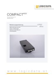
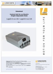
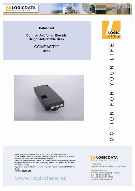
<strong>Data</strong>sheet<br />
Control Unit for an Electric<br />
Height-Adjustable Desk<br />
COMPACT eco<br />
Rev 0<br />
Subject to change without notice. Errors and omissions excepted.<br />
<strong>LOGICDATA</strong> cannot accept responsibility for incorrect operation or use of<br />
the products other than for the intended purpose.<br />
Under the warranty terms, <strong>LOGICDATA</strong> shall replace or repair any products<br />
that prove defective at the time of delivery. <strong>LOGICDATA</strong> shall not assume<br />
any further liability.<br />
If you have any questions or special requests, please contact <strong>LOGICDATA</strong><br />
direct.<br />
2012 <strong>LOGICDATA</strong>
Contents<br />
1. Features .............................................................................................................. 3<br />
2. Type and Dimensions .......................................................................................... 4<br />
<strong>3.</strong> <strong>Technical</strong> <strong>Data</strong> .................................................................................................... 5<br />
<strong>3.</strong>1 Pin assignments ........................................................................................... 6<br />
<strong>3.</strong>1.1 Motor socket .......................................................................................... 7<br />
<strong>3.</strong>1.2 Handset socket ..................................................................................... 7<br />
<strong>3.</strong>1.3 Logic Connector DATA ......................................................................... 8<br />
<strong>3.</strong>2 Functionality ................................................................................................. 8<br />
<strong>3.</strong>3 Intelligent System Protection (ISP) - Anti Pinch ........................................... 9<br />
<strong>3.</strong>4 Type Label ................................................................................................. 10<br />
4. Accessories ....................................................................................................... 11<br />
5. Order Code ........................................................................................................ 11<br />
6. Final Disposal .................................................................................................... 11<br />
7. Standards .......................................................................................................... 12<br />
8. Manufacturer Information .................................................................................. 12<br />
Page 2 / 12
1. Features<br />
High efficient switch mode power supply (SMPS)<br />
Low standby power consumption, low field emission<br />
Control units with US and EU input voltage available<br />
ISP (Intelligent System Protection)<br />
Enhanced Drive Comfort<br />
Safety area<br />
Low speed area<br />
InBox Diagnosis<br />
LogicConnector DATA for sensors and cascading<br />
Additional functions are available, depending on the handswitch model used<br />
(e.g. saving desktop positions, adjusting the desktop to saved positions, etc.)<br />
A wide selection of <strong>LOGICDATA</strong> handswitches is available for the control units<br />
Caution: do not open the device! Risk of electric shock!<br />
WARNING<br />
Avoid damaging the AC plug and power cord. Never operate this unit if the power<br />
cord is damaged. Use only the provided power cord.<br />
Connect the plug only to an electrical source matching the type label.<br />
Never operate this unit until the control box is mounted and fully installed.<br />
Never operate the control box until it is mounted and fully installed.<br />
CAUTION<br />
Do not open this unit. Uninsulated parts within the product‘s enclosure may expose<br />
you to dangerous voltage. Servicing may only be carried out by qualified personnel.<br />
Contact <strong>LOGICDATA</strong>.<br />
To prevent fire or shock hazard, do not expose this device to rain or moisture.<br />
Unplug the power cord before cleaning this unit. Only use a soft cloth, avoid abrasive<br />
cleaners.<br />
If you are not using the device for a long period of time, it is recommended to unplug<br />
the power cord.<br />
If strange smells or fume occur, unplug the power cord immediately. Contact<br />
<strong>LOGICDATA</strong>.<br />
Page 3 / 12
Note: information about usage of the COMPACT eco can be found in the<br />
user manual which is valid for the firmware version of the COMPACT eco .<br />
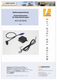
2. Type and Dimensions<br />
6,8<br />
2,8<br />
264<br />
252<br />
1) Dimensions in mm; Tolerances according to DIN ISO 2768-1 c<br />
1)<br />
Page 4 / 12<br />
42<br />
13<br />
A drill template can be found in the Mounting<br />
Instructions, available as separate document.<br />
45<br />
103<br />
5<br />
37
<strong>3.</strong> <strong>Technical</strong> <strong>Data</strong><br />
General<br />
Supply voltage EU: 207-254,4V / 50Hz<br />
US: 90-127V / 50-60Hz<br />
Nominal voltage EU: 230V / 50Hz<br />
US: 120V / 60Hz<br />
Standby power, primary (typical) ≤0,3 W<br />
Operating voltage for internal and external 5VDC 10% 250mA<br />
electronics and Hall sensors<br />
Precision of Motor current measurement<br />
@ 100% Output Voltage and 4-8A per Motor<br />
Page 5 / 12<br />
±15%<br />
Ambient temperature 0-30°C<br />
Relative humidity (for operation) 5-85% (non condensing)<br />
Storage and transport temperature -40-85°C<br />
Relative humidity (for storage) 5-90% (non condensing)<br />
Protection class (with earth terminal) I<br />
IP class IP 20<br />
Dimensions (L x B x H) [mm] 264 x 103 x 37<br />
COMPACT-e-3<br />
Switching cycles<br />
Depicted currents are sums over all motor<br />
channels<br />
1)<br />
Hi Power cycle:<br />
20s UP: 19A@20V 380W<br />
20s DOWN: 7A@33V 231W<br />
Pause: 9min<br />
Normal cycle 1/9:<br />
30s UP: 15A@24V 360W<br />
30s DOWN: 7A@33V 231W<br />
Pause: 9min<br />
Normal cycle 2/18:<br />
2min move: 7A@33V 231W<br />
Pause: 18min<br />
Max. current per motor channel 8A<br />
Maximum sum current restricted<br />
according to values shown above<br />
Weight (typical) 523g<br />
1) Dimensions in mm; Tolerances according to DIN ISO 2768-1 c
COMPACT-e-2<br />
Switching cycles<br />
Depicted currents are sums over all motor<br />
channels<br />
Page 6 / 12<br />
Hi Power cycle:<br />
20s UP: 15A@20V 300W<br />
20s DOWN: 4A@33V 132W<br />
Pause: 9min<br />
Normal cycle 1/9:<br />
30s UP: 12A@24V 288W<br />
30s DOWN: 4A@33V 132W<br />
Pause: 9min<br />
Normal cycle 2/18:<br />
2min move: 4A@33V 132W<br />
Pause: 18min<br />
Max. current per motor channel 8A<br />
Maximum sum current restricted<br />
according to values shown above<br />
Weight (typical) 418g<br />
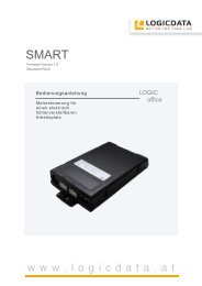
<strong>3.</strong>1 Pin assignments<br />
S<br />
D<br />
1<br />
� Motor socket 1 (M1)<br />
� Motor socket 2 (M2)<br />
� Motor socket 3 (M3)<br />
S Handswitch socket (HS)<br />
P Mains socket<br />
F Functional earth, cable lug for earthing the desk frame (6,3x0,8mm lug)<br />
D Logic Connector DATA for sensors and cascading<br />
2<br />
3<br />
Danger: it is not allowed to connect self constructed products to<br />
<strong>LOGICDATA</strong> motor controls. To prevent damage of the unit, use only<br />
components suitable for <strong>LOGICDATA</strong> motor controls.<br />
P<br />
F
<strong>3.</strong>1.1 Motor socket<br />
Danger: to prevent damage of the unit, use only motors/ motor cables<br />
suitable for <strong>LOGICDATA</strong> motor controls.<br />
Pin Description<br />
Motor+ / Motor - Power supply lines for motors<br />
Hallsensor 1,2 Sensor input lines for hall sensors<br />
+5V, GND Power supply lines (e.g. for hall sensors)<br />
SYN Reserved<br />
Limit Switch 1,2 Digital sensor input lines for limit switches<br />
7 6<br />
3 1<br />
5 2 4<br />
8 7 6 5<br />
1 2 3 4<br />
Danger: the maximum load for the 5V circuit is 250mA, this means that<br />
the combined load on all interfaces must not exceed this value!<br />
<strong>3.</strong>1.2 Handset socket<br />
(pin alignment according to DIN 45329)<br />
1 Hallsensor1 5 Hallsensor 2, Limit switch 1<br />
2 +5V 6 SYN<br />
3 Limit Switch2 7 Ground<br />
4 Motor+ 8 Motor-<br />
1 RxD 5 HS2<br />
2 HS3 6 TxD<br />
3 HS1 7 +5V<br />
4 HS4 Shell Ground<br />
Danger: to prevent damage of the unit, use only handswitches suitable<br />
for <strong>LOGICDATA</strong> motor controls.<br />
Pin Description<br />
TxD / RxD Pins for communication<br />
(<strong>LOGICDATA</strong> communication protocol)<br />
+5V, GND Power supply lines for handswitch<br />
HS X Parallel handswitch input lines<br />
Danger: the maximum load for the 5V circuit is 250mA, this means that<br />
the combined load on all interfaces must not exceed this value!<br />
Page 7 / 12
Note: please contact <strong>LOGICDATA</strong> for information about the coding of<br />
the parallel handswitch input lines!<br />
<strong>3.</strong>1.3 Logic Connector DATA<br />
8 7 6 5<br />
1 2 3 4<br />
Danger: to prevent damage of the unit, use only accessories suitable for<br />
<strong>LOGICDATA</strong> motor controls.<br />
Danger: be sure that the connector is plugged in correctly in the socket!<br />
Danger: when components like sensors shall be disconnected from the<br />
LogicConnector DATA, be sure to unlock the 8pin connector on the cable<br />
properly! There is a fixing hook on this connector which must be pressed.<br />
Pin Description<br />
TxD / RxD Pins for communication<br />
(<strong>LOGICDATA</strong> communication protocol)<br />
+5V, GND Power supply lines<br />
Signal 1,2 Digital I/O lines<br />
Signal 3,4 Analogue input lines<br />
Danger: the maximum load for the 5V circuit is 250mA, this means that<br />
the combined load on all interfaces must not exceed this value!<br />
<strong>3.</strong>2 Functionality<br />
1 RxD 5 Signal 2<br />
2 GND 6 Signal 1<br />
3 Signal 3 7 +5V<br />
4 Signal 4 8 TxD<br />
Table height display with configurable offset<br />
Compatibility to all <strong>LOGICDATA</strong> handsets<br />
Motor Auto-detection<br />
Plug detection<br />
Configurable stop conditions (overtemperature, overcurrent, timeout, limit<br />
switches)<br />
Configurable reset conditions<br />
Hall sensor configuration per motor group (one, two or differential Hall sensors)<br />
Up to 6 memory positions (depending on handset)<br />
ISP (Intelligent system protection) with drive back function<br />
Page 8 / 12
<strong>3.</strong>3 Intelligent System Protection (ISP) - Anti Pinch<br />
Pay attention to the following instructions if you are using the new anti-pinch feature<br />
ISP ( = Intelligent System Protection).<br />
To ensure optimal operation of the anti-pinch function during downwards travel, a<br />
mechanical braking system has to be integrated in the motor.<br />
Without such a braking system you have to expect decreased stop sensitivity<br />
under load. However, when the table is unloaded, the anti-pinch function will<br />
operate satisfyingly. Notice that the stop sensitivity is considerably influenced by<br />
mechanical construction of the table, motor and ambient conditions.<br />
The anti-pinch function drastically reduces the risk of injuries. However, we point<br />
out that we cannot be held liable in the case of mal operation, because the antipinch<br />
function interacts with mechanics, motor activity and electronics.<br />
Danger: systems containing the <strong>LOGICDATA</strong> Control Unit with antipinch<br />
function will reduce the risk of injury. Be aware that <strong>LOGICDATA</strong><br />
cannot completely eliminate this risk.<br />
Note: the ISP-sensitivity and the ISP-cutoff value depend on the whole<br />
system (mechanical and electrical components). To evaluate the ISPcapability<br />
of a height adjustable table, please contact <strong>LOGICDATA</strong>!<br />
Page 9 / 12
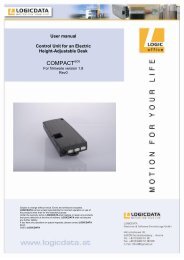
<strong>3.</strong>4 Type Label<br />
The following figure shows the type label and its location on the control box housing.<br />
Note: specifications on the type label are dependent on the version of<br />
the COMPACT eco control box (see technical data).<br />
Text alignment<br />
on the type plate<br />
Page 10 / 12
4. Accessories<br />
<strong>LOGICDATA</strong> offers a wide range of optional accessories. Please contact<br />
<strong>LOGICDATA</strong> to get a catalogue with all <strong>LOGICDATA</strong> products.<br />
5. Order Code<br />
COMPACT-e-N-n-x-y-z<br />
6. Final Disposal<br />
-> EU<br />
-> US<br />
-> Customer code<br />
-> Standard =<br />
„LD“<br />
Motor type (optional)<br />
Number of used motors (optional,<br />
depending on parameters)<br />
2…..up to 2 motors, LogicConnector DATA not activated<br />
2L…up to 2 motors, LogicConnector DATA activated<br />
3…..up to 3 motors, LogicConnector DATA activated<br />
Heed following disposal instructions when disposing of the COMPACT eco control box:<br />
Note: the COMPACT eco motor control box is electrical or electronic<br />
equipment according to directive 2002/96/EC and is therefore marked<br />
with the symbol depicted on the left.<br />
Note: ensure eco-friendly disposal of all the control unit components<br />
(separate the plastic and electronic parts for collection).<br />
Also ensure eco-friendly disposal of all the other components (drives,<br />
cables, etc.).<br />
Page 11 / 12
7. Standards<br />
Europa<br />
DIN EN 60335-1:2002 + A11:2004 + A1:2004 + A12:2006 + A2:2006 + A13:2008<br />
+ A14:2010<br />
DIN EN 61000-6-3*VDE 0839-6-3: 2007 09<br />
DIN EN 61000-6-2*VDE 0839-6-2: 2006 03<br />
DIN EN 61000-3-2:2006<br />
DIN EN 61000-3-3:2007<br />
SELV according to EN60335-1<br />
USA und Kanada<br />
cULus 60950-1 2 nd Edition Issue Date 2007-03-27<br />
CSA C22.2 60950-1-07<br />
Australien<br />
IEC 60335-1:2006<br />
DIN EN 61000-6-3*VDE 0839-6-3: 2007 09<br />
DIN EN 61000-6-2*VDE 0839-6-2: 2006 03<br />
Note: this product is RoHS compliant according to directive 2002/95/EC!<br />
Note: this product is REACH compliant according to directive<br />
2006/121/EC (Edict 1907/2006)<br />
8. Manufacturer Information<br />
<strong>LOGICDATA</strong><br />
Electronic & Software Entwicklungs GmbH<br />
Wirtschaftspark 18<br />
A-8530 Deutschlandsberg<br />
Page 12 / 12<br />
Tel.: +43 (0)3462 5198 0<br />
Fax: +43 (0)3462 5198 530<br />
Email: office@logicdata.at<br />
www.logicdata.at