2. COMPACT - LOGICDATA
2. COMPACT - LOGICDATA
2. COMPACT - LOGICDATA

Create successful ePaper yourself
Turn your PDF publications into a flip-book with our unique Google optimized e-Paper software.
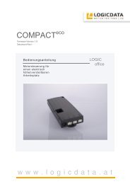
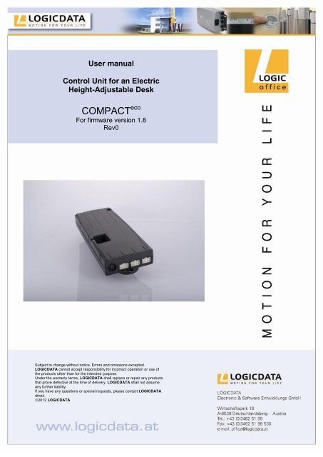
User manual<br />
Control Unit for an Electric<br />
Height-Adjustable Desk<br />
<strong>COMPACT</strong> eco<br />
For firmware version 1.8<br />
Rev0<br />
Subject to change without notice. Errors and omissions excepted.<br />
<strong>LOGICDATA</strong> cannot accept responsibility for incorrect operation or use of<br />
the products other than for the intended purpose.<br />
Under the warranty terms, <strong>LOGICDATA</strong> shall replace or repair any products<br />
that prove defective at the time of delivery. <strong>LOGICDATA</strong> shall not assume<br />
any further liability.<br />
If you have any questions or special requests, please contact <strong>LOGICDATA</strong><br />
direct.<br />
2012 <strong>LOGICDATA</strong>
Contents<br />
1. Preface ................................................................................................................ 4<br />
1.1 Intended use ................................................................................................ 4<br />
1.2 <strong>COMPACT</strong> eco control unit functionality ......................................................... 4<br />
1.3 Target group and previous knowledge ......................................................... 5<br />
1.4 Symbols used in safety instructions ............................................................. 5<br />
1.5 ISP (Intelligent System Protection) ............................................................... 6<br />
1.6 Package contents ......................................................................................... 7<br />
1.7 Unpacking .................................................................................................... 7<br />
1.8 Safety instructions ........................................................................................ 7<br />
1.8.1 General safety instructions .................................................................... 8<br />
1.8.2 Important notes for OEMs ................................................................... 10<br />
1.9 Important note for service ........................................................................... 10<br />
<strong>2.</strong> <strong>COMPACT</strong> eco installation instructions ................................................................ 11<br />
3. Commissioning .................................................................................................. 12<br />
3.1 <strong>COMPACT</strong> sockets .................................................................................... 12<br />
3.2 Commissioning procedure .......................................................................... 13<br />
3.<strong>2.</strong>1 Connect drives .................................................................................... 13<br />
3.<strong>2.</strong>2 Connect handswitch ............................................................................ 13<br />
3.<strong>2.</strong>3 Connect optional components ............................................................. 13<br />
3.<strong>2.</strong>4 Connect mains supply ......................................................................... 14<br />
3.<strong>2.</strong>5 System configuration (example) .......................................................... 15<br />
4. Operating the <strong>COMPACT</strong> eco control unit ........................................................... 16<br />
4.1 Basic functions ........................................................................................... 16<br />
4.1.1 Upward desktop movement................................................................. 16<br />
4.1.2 Downward desktop movement ............................................................ 17<br />
4.2 Advanced functions .................................................................................... 17<br />
4.<strong>2.</strong>1 Saving a desktop position ................................................................... 17<br />
4.<strong>2.</strong>2 Adjusting the desktop to a saved position ........................................... 18<br />
4.<strong>2.</strong>3 Changing the desktop height displayed .............................................. 19<br />
4.<strong>2.</strong>4 Manual reset ....................................................................................... 20<br />
4.<strong>2.</strong>5 Enabling limit position calibration ........................................................ 21<br />
4.<strong>2.</strong>6 Limit position calibration ...................................................................... 22<br />
4.3 Software-dependent functions .................................................................... 23<br />
4.3.1 Slow speed ranges .............................................................................. 23<br />
4.3.2 Safety area .......................................................................................... 23<br />
4.3.3 Container- and Shelf-Stop positions .................................................... 24<br />
4.3.4 Plug detection ..................................................................................... 25<br />
4.3.5 Drive Back ........................................................................................... 26<br />
4.3.6 Anti-Pinch configuration ...................................................................... 26<br />
4.3.7 Duty cycle monitoring .......................................................................... 27<br />
4.3.8 Change the displayed desktop position (cm or inch) ........................... 28<br />
4.3.9 Reset control unit to factory settings ................................................... 29<br />
4.3.10 Cascading ........................................................................................... 29<br />
4.3.11 Change number of drives .................................................................... 30<br />
Page 2 / 41
5. Appendix ........................................................................................................... 32<br />
5.1 Possible faults and remedies ..................................................................... 32<br />
5.2 Error messages on the handswitch display ................................................ 33<br />
5.3 Error indication with LEDs .......................................................................... 35<br />
5.4 Click codes ................................................................................................. 37<br />
5.5 Drill template .............................................................................................. 38<br />
6. Further information ............................................................................................ 40<br />
6.1 End of life disposal ..................................................................................... 40<br />
6.2 Technical data ............................................................................................ 40<br />
6.3 Optional products ....................................................................................... 40<br />
6.4 Manufacturer .............................................................................................. 40<br />
Page 3 / 41
1. Preface<br />
Dear Customer,<br />
Thank you for choosing a <strong>COMPACT</strong> eco control unit for electric height-adjustable<br />
desks from <strong>LOGICDATA</strong> Electronic & Software Entwicklungs GmbH. You are<br />
now in possession of a state-of-the-art product that complies with all the relevant<br />
safety requirements.<br />
1.1 Intended use<br />
<strong>COMPACT</strong> eco control units may only be used for the intended purpose, i.e. to control<br />
electric height-adjustable desks. Only motors that meet <strong>LOGICDATA</strong> specifications<br />
may be used to drive the lifting devices. The control units must be installed, put into<br />
operation and their function checked by qualified personnel. Using them to control<br />
other motors or installing them in products other than electric height-adjustable desks<br />
is only permissible with the prior written consent of <strong>LOGICDATA</strong>. Their basic<br />
function is upward and downward adjustment of the desktop, which can be controlled<br />
with all the handswitches available.<br />
1.2 <strong>COMPACT</strong> eco control unit functionality<br />
The <strong>COMPACT</strong> eco control units incorporate the following features (the availability of<br />
some of the features depends on the handswitch used):<br />
High efficient switch mode power supply (SMPS)<br />
Low standby power consumption, low field emission<br />
Control units with US and EU input voltage available<br />
Up to 2 motor groups<br />
ISP (Intelligent System Protection)<br />
Enhanced Drive Comfort<br />
Safety area<br />
Container- and Shelf-Stop<br />
Low speed area<br />
InBox Diagnosis<br />
LogicConnector DATA for sensors and cascading<br />
Additional functions are available, depending on the handswitch model used<br />
(e.g. saving desktop positions, adjusting the desktop to saved positions, etc.)<br />
A wide selection of <strong>LOGICDATA</strong> handswitches is available for the control units<br />
Page 4 / 41
1.3 Target group and previous knowledge<br />
This user manual addresses the following people:<br />
Technicians who assemble and put electric height-adjustable desks into operation<br />
(by installing motors and control units, configuring control units, etc.)<br />
Furniture assembly, service and maintenance personnel who put electric heightadjustable<br />
desks into operation in showrooms or at the customer’s<br />
The following is required for installing, operating and configuring electric heightadjustable<br />
desks with <strong>COMPACT</strong> eco control units:<br />
Basic mechanical and electrical skills (with suitable qualifications)<br />
Reading the user manual<br />
1.4 Symbols used in safety instructions<br />
This user manual contains safety instructions with symbols drawing your attention to<br />
possible dangers and residual risks. They indicate the following:<br />
Danger: this warning symbol advises you of imminent danger to people’s<br />
lives and health.<br />
Failure to observe this warning may result in health problems, serious<br />
injuries and damage to property.<br />
Caution: this warning advises you of possible dangers from electric<br />
current.<br />
Failure to observe this warning may cause injuries and damage to<br />
property.<br />
Note: this symbol advises you of important information that must be<br />
noted for operating the <strong>COMPACT</strong> eco control unit safely.<br />
Danger: this warning advises you of a possible risk of body parts being<br />
trapped or pinched in exceptional cases.<br />
Failure to observe this warning may result in health problems, serious<br />
injuries and damage to property.<br />
Note: you must read the user manual.<br />
Page 5 / 41
1.5 ISP (Intelligent System Protection)<br />
ISP is an electronic state-of-the-art protection system developed by <strong>LOGICDATA</strong>. It<br />
also substantially reduces the risk of fingers being trapped or pinched.<br />
Danger: in spite of ISP being in place, there may still be a risk of<br />
pinching in exceptional cases, as it is not only the control unit, but also<br />
the interaction between the mechanical and electronic systems that is<br />
responsible for cutting out the motor. In addition, the mechanical<br />
components, motor and ambient conditions all affect cut-out sensitivity.<br />
As the control unit manufacturer, <strong>LOGICDATA</strong> cannot therefore<br />
eliminate this residual risk completely or accept any liability.<br />
Note: the ISP-sensitivity and the ISP-cutoff value depend on the whole<br />
system (mechanical and electrical components). To evaluate the ISPcapability<br />
of a height adjustable table, please contact <strong>LOGICDATA</strong>!<br />
Please note the following for maximizing ISP functionality:<br />
To ensure the best possible pinch protection, a mechanical brake must be fitted that<br />
is applied when the electric height-adjustable desk moves down.<br />
Note: without a mechanical brake, cut-out sensitivity may be reduced<br />
under load. However, if there is no load on the desktop, ISP will function<br />
properly even without a brake.<br />
Note: as soon as ISP has stopped the electric height-adjustable desk<br />
from moving, you can then only adjust the desktop in the opposite<br />
direction (the safety feature initially prevents you from adjusting the desk<br />
in the same direction as triggered it).<br />
Page 6 / 41
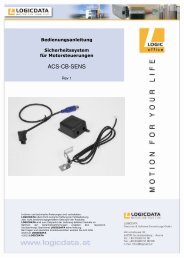
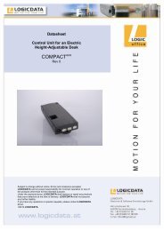
1.6 Package contents<br />
The <strong>COMPACT</strong> eco control unit is supplied together with the following components as<br />
standard:<br />
Figure 1: Package contents<br />
� <strong>COMPACT</strong> eco control unit<br />
1.7 Unpacking<br />
1<br />
Note: power cords can be ordered separately.<br />
The <strong>COMPACT</strong> eco control unit comes packed in a cardboard box. Some components<br />
are also sealed in plastic film. To unpack, proceed as follows:<br />
1. Remove the cardboard and plastic film from the control unit components.<br />
<strong>2.</strong> Check the package contents.<br />
3. Dispose of the packaging materials.<br />
4. Keep the user manual at hand for the operators.<br />
Note: ensure eco-friendly disposal of the packaging materials (separate<br />
the plastic parts and cardboard for collection).<br />
1.8 Safety instructions<br />
This user manual contains safety instructions that draw your attention to any possible<br />
risks, thus enabling safe operation of the <strong>COMPACT</strong> eco control unit. Please observe<br />
these warnings and instructions at all times.<br />
In this section you will find general safety instructions that do not refer to any<br />
particular steps or procedures. You will find the work-specific safety instructions in<br />
the relevant section of the manual. Additional warnings are given on the<br />
<strong>COMPACT</strong> eco control unit itself.<br />
Page 7 / 41
1.8.1 General safety instructions<br />
Note: you must read the user manual carefully before installing or<br />
operating the <strong>COMPACT</strong> eco control unit.<br />
Caution: do not open the <strong>COMPACT</strong> eco control unit under any<br />
circumstances. There is a danger of electric shock.<br />
Caution: the <strong>COMPACT</strong> eco control unit is not designed for continuous<br />
operation. Changing the desktop position without interruption must not<br />
exceed the duty cycle indicated on the nameplate.<br />
Caution: the <strong>COMPACT</strong> eco control unit may only be operated with mains<br />
voltage as specified on the type plate.<br />
<strong>COMPACT</strong> eco control units are also available for the mains voltages used<br />
in other countries.<br />
Caution: only use the power cord supplied with the control unit. Check<br />
that it is not damaged. Do not ever operate the <strong>COMPACT</strong> eco control unit<br />
if the power cord is damaged.<br />
Danger: it is not allowed to connect self constructed products to<br />
<strong>LOGICDATA</strong> motor controls. To prevent damage of the unit, use only<br />
components suitable for <strong>LOGICDATA</strong> motor controls.<br />
Caution: before connecting and disconnecting handswitches, you must<br />
unplug the power cord.<br />
Caution: in the event of a malfunction (e.g. if the control unit keeps<br />
adjusting the desk because a movement key has jammed), please<br />
unplug the unit immediately.<br />
Danger: do not expose the <strong>COMPACT</strong> eco control unit to moisture, drips<br />
or splashes.<br />
Danger: when changing the desktop position (especially without using<br />
pinch protection), there is a risk of pinching. You must therefore ensure<br />
that no people or objects are located in the hazardous area or can reach<br />
into it.<br />
Page 8 / 41
Danger: when changing the desktop position, there may in exceptional<br />
cases be a risk of pinching in spite of the safety features. You must<br />
therefore always ensure that no people or objects are located in the<br />
hazardous area or reach into it.<br />
Danger: do not modify or make any changes to the control unit, the<br />
controls themselves or handswitches.<br />
Danger: do not operate the <strong>COMPACT</strong> eco control unit in a potentially<br />
explosive atmosphere.<br />
Danger: in the event of a fault (motor or component), whenever the<br />
desktop attempts to adjust the height it may move slightly before the<br />
safety cut-out is triggered. Please note that there is a potential risk of<br />
pinching in this case.<br />
Danger: intelligent system protection (ISP) is not enabled during all<br />
resets (see chapter 4.<strong>2.</strong>4) and limit position calibration (see chapter<br />
4.<strong>2.</strong>6). Please note that there is a potential risk of pinching in this case.<br />
Danger: this device is not intended for use by individuals (including<br />
children) with limited physical, sensory or mental abilities or with a lack of<br />
experience and/or lack of expertise, unless they are supervised by a<br />
person responsible for their safety or have received instructions from that<br />
person on how to use the control unit.<br />
Danger: children must be supervised at all times to ensure that they do<br />
not play with the control unit.<br />
Danger: if the control unit’s power cord is damaged, it must be replaced<br />
by the manufacturer or customer service or similarly qualified person in<br />
order to prevent any risks.<br />
Note: only clean the <strong>COMPACT</strong> eco control unit with a dry or slightly moist<br />
cloth. Before cleaning, you must always unplug the power cord.<br />
Note: in case of a mains power breakdown or if the power cord is<br />
plugged off during the movement of the drives, a manual reset of the<br />
<strong>COMPACT</strong> eco may be necessary!<br />
Page 9 / 41
1.8.2 Important notes for OEMs<br />
What we mean by OEMs are companies that purchase <strong>COMPACT</strong> eco control units<br />
from <strong>LOGICDATA</strong> and install them in their own products (e.g. electric heightadjustable<br />
desks).<br />
Note: for reasons of EU conformity and product safety, we advise you to<br />
provide users of your products with a manual in the relevant EU<br />
language.<br />
Note: when you ship your finished products, enclose a user manual<br />
containing all the safety instructions that consumers need to handle your<br />
product safely.<br />
Note: the user manual for your finished product must contain the<br />
following note: you must read the user manual before you operate the<br />
product (electric height-adjustable desk).<br />
Advise your customers that the user manual must be kept at hand in<br />
close proximity to the product (electric height-adjustable desk).<br />
Danger: conduct a risk analysis of your product (electric heightadjustable<br />
desk) so that you can respond to any potential residual risks<br />
(e.g. by changing design features or adding notes to the user manual<br />
and/or placing warnings on your product).<br />
Note: ensure that no unauthorized individuals (e.g. small children,<br />
people under the influence of drugs, etc.) can tamper with your product<br />
or the control unit.<br />
1.9 Important note for service<br />
Danger: only use original spare parts. Parts may only be replaced by<br />
qualified service technicians, otherwise the warranty/guarantee shall be<br />
null and void.<br />
Danger: in the event of a fault, please contact customer service<br />
immediately. Only original spare parts may be used for repairing the<br />
control units. Parts may only be replaced by qualified service<br />
technicians, otherwise the warranty/guarantee shall be null and void.<br />
Page 10 / 41
<strong>2.</strong> <strong>COMPACT</strong> eco installation instructions<br />
Mount the <strong>COMPACT</strong> eco control unit on the underside of the desktop. You will need<br />
the following tools for mounting:<br />
Cross-tip screwdriver<br />
Pencil<br />
Drill (for drilling holes)<br />
Caution: the power cord must be unplugged while the <strong>COMPACT</strong> eco<br />
control unit is being mounted.<br />
To mount the <strong>COMPACT</strong> eco control unit, proceed as follows:<br />
Note: we recommend using the drill template to help with mounting. You<br />
will find the template in section 5.50. If you do not wish to use it, please<br />
follow the mounting instructions carefully.<br />
1. Position the control unit where you want it under the desktop.<br />
<strong>2.</strong> Mark the drill holes with a pencil.<br />
Figure 2: Step 2<br />
3. Pre-drill these two holes.<br />
4. Attach the control unit with 2 screws by using these two holes.<br />
5. Tighten the two screws properly.<br />
Note: <strong>LOGICDATA</strong> recommends lens head screws DIN7981C 4,8xL<br />
with a lens head diameter of 9,5mm. The length L of the screw should fit<br />
to the used desktop. The tightening torque depends on the wood, but<br />
2Nm shall not be exceeded.<br />
Page 11 / 41
3. Commissioning<br />
Commissioning involves the procedures required to ensure that the height of an<br />
electric height-adjustable desk can be adjusted with the <strong>COMPACT</strong> eco control unit.<br />
Requirements for commissioning:<br />
The <strong>COMPACT</strong> eco control unit must be mounted (as described in section 2)<br />
The table legs for adjusting the desktop must be mounted<br />
Danger: only qualified technicians may commission the control unit.<br />
Qualified technicians have the necessary electrical engineering training<br />
and are familiar with this user manual.<br />
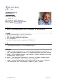
3.1 <strong>COMPACT</strong> sockets<br />
The <strong>COMPACT</strong> eco control unit (<strong>COMPACT</strong>-3 can drive three motors) has the<br />
following sockets:<br />
Figure 3: Sockets<br />
S<br />
D<br />
1<br />
� Motor socket 1 (M1)<br />
� Motor socket 2 (M2)<br />
� Motor socket 3 (M3)<br />
S Handswitch socket (HS)<br />
P Mains socket<br />
F Functional earth, cable lug for earthing the desk frame (6,3x0,8mm lug)<br />
D Logic Connector DATA for sensors and cascading<br />
2<br />
3<br />
Danger: it is not allowed to connect self constructed products to<br />
<strong>LOGICDATA</strong> motor controls. To prevent damage of the unit, use only<br />
components suitable for <strong>LOGICDATA</strong> motor controls.<br />
Page 12 / 41<br />
P<br />
F
Note: the clamp next to the mains socket is used as a connector for a<br />
functional earth. This clamp is used for example to deflect electrostatic<br />
charge from the electric height-adjustable desk. The connector cannot<br />
carry out the function of a protective conductor!<br />
This clamp is also marked with the symbol on top of the housing.<br />
3.2 Commissioning procedure<br />
Caution: the power cord must be unplugged while the <strong>COMPACT</strong> eco<br />
control unit is being commissioned.<br />
To commission a <strong>COMPACT</strong> eco control unit, proceed as follows.<br />
3.<strong>2.</strong>1 Connect drives<br />
Plug the motor cables into the relevant 8-pin motor sockets (M1, M2, and M3).<br />
Note: when connecting the motor cables, you must strictly adhere to the<br />
sequence M1, M2, M3.<br />
Danger: during commissioning a system with single-end-limit switches<br />
(connection of upper and lower signal limit switches in series) or when<br />
changing a motor on such a system, the motors must not be extended to<br />
their highest position. (upper limit switch active)<br />
3.<strong>2.</strong>2 Connect handswitch<br />
Plug the handswitch into the 7-pin socket (HS).<br />
Note: you can choose from a wide range of <strong>LOGICDATA</strong> handswitches<br />
for the <strong>COMPACT</strong> eco control unit. Information about available<br />
handswitches can be found in the latest product catalogue and on the<br />
website www.logicdata.at .<br />
3.<strong>2.</strong>3 Connect optional components<br />
If your control unit has an earthing cable lug, attach a cable to a metal part of the<br />
desk.<br />
If your control unit has a LogicConnector DATA, you can connect accessories like<br />
sensors.<br />
Page 13 / 41
Note: to determine whether the LogicConnector DATA is activated,<br />
please compare the product name on the nameplate with the order code<br />
which is shown in the appropriate datasheet.<br />
Danger: when components like sensors shall be disconnected from the<br />
LogicConnector DATA, be sure to unlock the 8pin connector on the cable<br />
properly! There is a fixing hook on this connector which must be pressed.<br />
3.<strong>2.</strong>4 Connect mains supply<br />
Caution: before you plug in the power cord, check the following again:<br />
The mains supply voltage must be as specified on the type plate<br />
All the components must be plugged into the right sockets<br />
The earthing cable must be connected<br />
When the power cord is plugged in, the <strong>COMPACT</strong> eco control unit is<br />
operational.<br />
Note: in case of a mains power breakdown or if the power cord is<br />
plugged off during the movement of the drives, a manual reset of the<br />
<strong>COMPACT</strong> eco may be necessary!<br />
Page 14 / 41
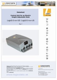
3.<strong>2.</strong>5 System configuration (example)<br />
The figure below shows the socket assignment for a configuration example. This<br />
configuration consists of:<br />
� 1 <strong>COMPACT</strong>-e-3 control unit<br />
� 3 motors (hidden in the table legs)<br />
� HSF-MDF-4M4-LD handswitch<br />
Figure 4: Configuration example<br />
2<br />
Page 15 / 41<br />
3<br />
1
4. Operating the <strong>COMPACT</strong> eco control unit<br />
To ensure safe operation of the <strong>COMPACT</strong> eco control unit, please observe the<br />
following safety instructions:<br />
Note: in case of a mains power breakdown or if the power cord is<br />
plugged off during the movement of the drives, a manual reset of the<br />
<strong>COMPACT</strong> eco may be necessary!<br />
Caution: keep children away from electric height-adjustable desks,<br />
control units and handswitches. There is risk of injury and electric shock.<br />
Caution: unplug the power cord during a thunderstorm or if you do not<br />
intend to use the desk for a longer period. The control unit might<br />
otherwise be damaged by power surges.<br />
4.1 Basic functions<br />
Note: the <strong>COMPACT</strong> eco control unit offers an extensive range of<br />
functions. The availability of some functions depends however on the<br />
handswitch used.<br />
This section describes the basic functions available with every<br />
handswitch designed for use with <strong>COMPACT</strong> eco control units.<br />
Note: the 2 basic functions upward and downward movement are<br />
available for both motorgroups separately. Please read the manual of the<br />
used handswitch to see which buttons are linked to which motor group!<br />
4.1.1 Upward desktop movement<br />
This function enables you to adjust the desktop upwards. To change its position,<br />
proceed as follows:<br />
Press the desktop up key.<br />
Keep pressing the key until the required desktop height is reached.<br />
Note: the desktop will continue moving upwards until you release the key<br />
or the maximum height is reached.<br />
Page 16 / 41
4.1.2 Downward desktop movement<br />
This function enables you to adjust the desktop downwards. To change its position,<br />
proceed as follows:<br />
Press the desktop down key.<br />
Keep pressing the key until the required desktop height is reached.<br />
Note: the desktop will continue moving downwards until you release the<br />
key or the minimum height is reached.<br />
4.2 Advanced functions<br />
Note: you can only use the following functions of the <strong>COMPACT</strong> eco<br />
control unit if you have a handswitch with memory position keys and a<br />
memory key.<br />
4.<strong>2.</strong>1 Saving a desktop position<br />
This function allows you to save a defined desktop height .One desktop height can<br />
be saved per memory position key. To save a position, proceed as follows:<br />
1.<br />
<strong>2.</strong><br />
3.<br />
Note: if you are switching on the <strong>COMPACT</strong> eco control unit for the first<br />
time, all the saved positions are set to the lowest desktop height<br />
(minimum desktop position).<br />
Adjust the desktop to the position you want to save.<br />
The display will show the desktop height (e.g. 73cm).<br />
Press the memory key.<br />
The display will read S –.<br />
Press the required memory position key (e.g. 2).<br />
The display will read S <strong>2.</strong><br />
4. The set desktop position will now be saved to the selected memory<br />
position key.<br />
You will hear an audible double click and after about 2 seconds the<br />
saved desktop position will be displayed.<br />
Note: using saved desktop positions is only available for handswitches<br />
with memory keys. The design of the memory position keys varies,<br />
depending on the handswitch model used.<br />
Page 17 / 41
Note: it is software parameter dependent which motor group can<br />
save/recall memory positions. If both motor groups are capable of saving<br />
memory positions, the current position of both groups will be stored<br />
(even if they are different). When recalling a stored position in this case,<br />
both groups start their movement at the same time, even if their<br />
movement direction is different.<br />
4.<strong>2.</strong>2 Adjusting the desktop to a saved position<br />
You can use this function to adjust the desktop to a saved height. To change to a<br />
saved position, proceed as follows:<br />
Note: availability of the double click function depends on the software<br />
configuration of the control unit.<br />
Option A (without double click function)<br />
1.<br />
Press the required memory position key (e.g. 2) and hold it down.<br />
The desktop will move until it reaches the saved position. If you<br />
release the key before the saved position is reached, the desktop will<br />
stop and the saved desktop position will not be reached.<br />
<strong>2.</strong> The desktop has reached the saved position. Now release the<br />
memory position key.<br />
The display will read the current (saved) desktop position.<br />
Option B (with double click function)<br />
1.<br />
Double click the required memory position key (e.g. 2).<br />
<strong>2.</strong> After the double click, the desktop will automatically adjust to the saved<br />
position.<br />
The display will show the current (saved) desktop position.<br />
Danger: when you change the desktop position automatically<br />
(especially without using pinch protection), there is a higher risk of<br />
pinching. You must therefore ensure that no people or objects are<br />
located in the hazardous area or reach into it.<br />
Note: if you press another key while the desktop is changing<br />
automatically to a saved position, it will stop immediately. You then<br />
have to reactivate automatic desktop adjustment to a preset position.<br />
Page 18 / 41
4.<strong>2.</strong>3 Changing the desktop height displayed<br />
This function enables you to change the height shown on the display, but not the<br />
actual position of the desktop. Proceed as follows:<br />
1.<br />
Press the memory key.<br />
<strong>2.</strong><br />
3.<br />
4.<br />
The display will read S –.<br />
Press the desktop down key (down arrow) for approx. 5<br />
seconds.<br />
The display will start flashing.<br />
Adjust the height displayed by pressing the desktop down<br />
(down arrow) or desktop up key (up arrow).<br />
Press the memory key.<br />
The height display is now set to the new desktop position<br />
entered.<br />
Note: please note that this procedure does not alter the actual position of<br />
the desktop. It only changes the height displayed.<br />
Note: this function is only available for handswitches with integrated<br />
display.<br />
Note: this function is available for both motorgroups separately. Please<br />
read the manual of the used handswitch to see which buttons are linked<br />
to which motor group!<br />
Page 19 / 41
4.<strong>2.</strong>4 Manual reset<br />
When the actual desktop position no longer corresponds to the height displayed or<br />
you wish to use a configured control unit on another identical electric heightadjustable<br />
desk, you have to reset the lowest desktop position to the minimum<br />
height.<br />
1.<br />
Press the desktop down key.<br />
Keep pressing it until the desktop has reached the lowest position<br />
(programmed desktop position).<br />
<strong>2.</strong><br />
Press the desktop down key again and keep pressing it.<br />
After about 5 seconds, the desktop will slowly move further down<br />
until it reaches the absolutely lowest desktop position possible.<br />
3. Release the desktop down key. The electric height-adjustable<br />
desk can now be used again normally.<br />
Danger: intelligent system protection (ISP) is not enabled during all<br />
resets and limit position calibration. Please note that there is a potential<br />
risk of pinching in this case.<br />
Note: this function is available for both motorgroups separately. Please<br />
read the manual of the used handswitch to see which buttons are linked<br />
to which motor group!<br />
Page 20 / 41
4.<strong>2.</strong>5 Enabling limit position calibration<br />
The service technician enables limit position calibration during the commissioning<br />
procedure.<br />
1.<br />
<strong>2.</strong><br />
3.<br />
Note: availability of the S 7 function depends on the parameters set for<br />
the control unit. A handswitch with display and memory keys is<br />
necessary.<br />
Note: this function is only available for motor group 1!<br />
Press the keys memory position 1, 2 and desktop up<br />
at the same time. Keep the key combination pressed<br />
for about 10 seconds. Then release the keys.<br />
The display will show S1.<br />
Press the desktop up key until the display reads S 7.<br />
The display will show S 7.<br />
Press the memory key.<br />
Note: after starting the menu, the display will read S and any number,<br />
for instance S 1. The number depends on the parameters of the control<br />
unit.<br />
Page 21 / 41
4.<strong>2.</strong>6 Limit position calibration<br />
The limit positions must be calibrated during commissioning after the control unit has<br />
been installed.<br />
Note: there is the option of having all the settings required for<br />
commissioning carried out at the factory.<br />
Note: a handswitch with display and memory keys is necessary.<br />
To calibrate the limit positions, proceed as follows:<br />
1.<br />
<strong>2.</strong><br />
068 flashes on the display.<br />
Note:<br />
068 is shown if the handswitch display is set up to show<br />
the height in centimetres.<br />
If the display is set up to show the height in inch, the<br />
display shows 027 in this step!<br />
Press the desktop down key until the desktop reaches<br />
the lowest position.<br />
3. Set the current desktop height on the display.<br />
4.<br />
5.<br />
Press memory position key 1 to increase the desktop<br />
position displayed (movement locked in every<br />
direction).<br />
Press memory position key 2 to decrease the desktop<br />
position displayed (movement locked in every<br />
direction).<br />
Press the memory key.<br />
088 will flash on the display.<br />
Note:<br />
088 is shown if the handswitch display is set up to show<br />
the height in centimetres.<br />
If the display is set up to show the height in inch, the<br />
display shows 035 in this step!<br />
Press the desktop up key until the desktop reaches the<br />
highest position.<br />
Page 22 / 41
6. Set the current desktop height on the display.<br />
7.<br />
Press memory position key 1 to increase the desktop<br />
position displayed.<br />
Press memory position key 2 to decrease the desktop<br />
position displayed.<br />
Press the memory key. The display will show the<br />
current desktop position (display no longer flashing).<br />
Danger: intelligent system protection (ISP) is not enabled during all<br />
resets and limit position calibration. Please note that there is a potential<br />
risk of pinching in this case.<br />
4.3 Software-dependent functions<br />
Note: prior to shipping, the <strong>COMPACT</strong> eco control unit is parameterized<br />
with the software. The following functions are only available if the control<br />
unit has been configured accordingly.<br />
4.3.1 Slow speed ranges<br />
This function (low speed area) automatically slows down the desktop during<br />
adjustment before it reaches the following positions:<br />
Highest and lowest desktop positions<br />
All saved positions (for example: memory-positions, container-stop-position)<br />
4.3.2 Safety area<br />
This function triggers a safety stop at a defined desktop position (configured with the<br />
software). The safety stop functions as follows:<br />
1.<br />
Press the desktop down key (and hold it down). The desktop will<br />
move to the start of the safety area.<br />
<strong>2.</strong> The desktop movement will stop just before the safety area.<br />
3.<br />
Press the desktop down key again. The desktop will then move to<br />
the lowest position.<br />
Note: you cannot save desktop positions in safety areas.<br />
Note: this function is available for both motorgroups separately. Please<br />
read the manual of the used handswitch to see which buttons are linked<br />
to which motor group!<br />
Page 23 / 41
4.3.3 Container- and Shelf-Stop positions<br />
These 2 features can be used to limit the movement area of the desktop (e.g. if a<br />
container is placed underneath the desktop). A container stop position can be<br />
defined in the lower half of the movement area, a shelf stop position in the upper half.<br />
If a container stop position is set, this position will be the lower limit position. If a shelf<br />
stop position is set, this position will be the new upper limit position. To store a<br />
container stop / shelf stop position, go on as shown below:<br />
1.<br />
<strong>2.</strong><br />
or<br />
Move the desktop to the position where the container stop/ shelf<br />
stop position shall be stored. Do so by pressing the desktop down<br />
or desktop up key until you reach the desired position.<br />
Note:<br />
A container stop position can only be stored in the lower half of the<br />
movement area and a shelf stop in the upper half.<br />
Press S for 10 seconds. The <strong>COMPACT</strong> eco will click twice when the<br />
container stop position is stored.<br />
Note: These steps have to be done for a container stop and a shelf stop<br />
position separately!<br />
To deactivate the container stop/ shelf stop position go on as shown below:<br />
1.<br />
<strong>2.</strong><br />
or<br />
Move the desktop to any position in the lower half to deactivate the<br />
container stop. / Move the desktop to any position in the upper half<br />
to deactivate the shelf stop.<br />
Do so by pressing the desktop down or desktop up key until you<br />
reach the desired position.<br />
Press S for 10 seconds. The <strong>COMPACT</strong> eco will click once when the<br />
container stop position is deactivated.<br />
Note: These steps have to be done for a container stop and a shelf stop<br />
position separately!<br />
Note: this function is only available for motor group 1!<br />
Page 24 / 41
4.3.4 Plug detection<br />
The <strong>COMPACT</strong> eco control unit can detect whether a motor is plugged into the<br />
relevant socket. In addition, the control unit detects whether a motor has been<br />
replaced (the availability of this function depends on the type of the control and the<br />
used drives).<br />
If a motor is missing or if it is replaced, the <strong>COMPACT</strong> eco will click three times.<br />
Additionally the corresponding error code will be displayed if the handswitch is<br />
equipped with a display (For the error code list, see chapter 5.2).<br />
To rectify the plug detection error, a manual reset is necessary (see chapter 4.<strong>2.</strong>4).<br />
In addition to the plug detection, the <strong>COMPACT</strong> eco is able to auto-detect the number<br />
of drives. This feature will be activated every time a motor is connected to or<br />
disconnected from the <strong>COMPACT</strong> eco , also at the first use of the control unit. To<br />
operate the <strong>COMPACT</strong> eco after such an event again, go on as shown below:<br />
1. Possible situations:<br />
<strong>2.</strong><br />
A motor is connected to the <strong>COMPACT</strong> eco<br />
A motor is disconnected from the <strong>COMPACT</strong> eco<br />
First use of the <strong>COMPACT</strong> eco<br />
The error code E70 is shown on the display.<br />
3. Disconnect the mains supply of the <strong>COMPACT</strong> eco and<br />
wait at least 5 seconds.<br />
4. Connect the mains supply of the <strong>COMPACT</strong> eco again.<br />
5. Make a manual reset (see chapter 4.<strong>2.</strong>4)<br />
Note: the functionality of the auto-detection is depending on the motor<br />
group settings in the software parameters of the <strong>COMPACT</strong> eco . Please<br />
contact <strong>LOGICDATA</strong> for further information!<br />
Note: a handswitch with display is necessary to show the error code.<br />
Page 25 / 41
4.3.5 Drive Back<br />
Note: the function Drive Back is only active, if a pinch protection system<br />
(ISP, switches or pinch protection strips) is available and activated in<br />
software!<br />
After a safety function is triggered by ISP, the desktop automatically moves a defined<br />
distance in the opposite direction. This immediately prevents any possible risk of<br />
pinching.<br />
Danger: in spite of ISP being in place, there may still be a risk of<br />
pinching in exceptional cases, as it is not only the control unit, but also<br />
the interaction between all the components in the electric heightadjustable<br />
desk that is responsible for cutting out the motor. In addition,<br />
the mechanical components, motor and ambient conditions all affect cutout<br />
sensitivity.<br />
As the control unit manufacturer, <strong>LOGICDATA</strong> does not have an effect<br />
on this residual risk and cannot therefore accept any liability.<br />
Please follow the safety instructions in the manual and treat our product<br />
with due care.<br />
4.3.6 Anti-Pinch configuration<br />
If the pinch protection device ACS-CB-SENS is attached to the <strong>COMPACT</strong> eco , the<br />
risk of pinches is decreased. To activate the ACS-CB-SENS, go on as shown below:<br />
1. Possible situations:<br />
<strong>2.</strong><br />
An ACS-CB-SENS is attached to the<br />
<strong>COMPACT</strong> eco<br />
An ACS-CB-SENS is attached to the<br />
<strong>COMPACT</strong> eco again after an error.<br />
First use of the <strong>COMPACT</strong> in combination with<br />
ACS-CB-SENS<br />
The error code E71 is shown on the display.<br />
3. Be sure that the ACS-CB-SENS is attached to the<br />
<strong>COMPACT</strong> eco properly.<br />
4. Disconnect the mains supply of the <strong>COMPACT</strong> eco and<br />
wait at least 5 seconds.<br />
5. Connect the mains supply of the <strong>COMPACT</strong> eco again.<br />
Page 26 / 41
To deactivate the ACS-CB-SENS, go on as shown below:<br />
1. Possible situation:<br />
<strong>2.</strong><br />
An ACS-CB-SENS is disconnected from the<br />
<strong>COMPACT</strong><br />
The error code E71 is shown on the display.<br />
3. Be sure that the ACS-CB-SENS is disconnected from<br />
the <strong>COMPACT</strong> eco .<br />
4.<br />
Press and hold the desktop up key until the desktop<br />
reaches the highest position.<br />
5. The <strong>COMPACT</strong> eco clicks three times to confirm that the<br />
ACS-CB-SENS configuration is deactivated.<br />
Danger: in spite of ACS-CB-SENS being in place, there may still be a<br />
risk of pinching in exceptional cases, as it is not only the control unit, but<br />
also the interaction between all the components in the electric heightadjustable<br />
desk that is responsible for cutting out the motor. In addition,<br />
the mechanical components, motor and ambient conditions all affect cutout<br />
sensitivity.<br />
As the control unit manufacturer, <strong>LOGICDATA</strong> does not have an effect<br />
on this residual risk and cannot therefore accept any liability.<br />
Please follow the safety instructions in the manual and treat our product<br />
with due care.<br />
Danger: deactivating the ACS-CB-SENS causes a higher risk of<br />
pinching. Other anti-pinch mechanisms like ISP stay active.<br />
As the control unit manufacturer, <strong>LOGICDATA</strong> does not have an effect<br />
on this residual risk and cannot therefore accept any liability.<br />
Please follow the safety instructions in the manual and treat our product<br />
with due care.<br />
4.3.7 Duty cycle monitoring<br />
Duty cycle monitoring means that when the control unit has been operating for a<br />
defined period, it is switched off for a set time (e.g. after 2 minute of continuous<br />
operation, the control unit is automatically disabled for the next 18 minutes).<br />
Page 27 / 41
4.3.8 Change the displayed desktop position (cm or inch)<br />
With this function it is possible to change the displayed desktop position from<br />
centimetres to inches or the other way around. The desktop position itself is not<br />
affected by this function.<br />
1.<br />
<strong>2.</strong><br />
3.<br />
Press the keys memory position 1, 2 and desktop up<br />
at the same time. Keep the key combination pressed<br />
for about 3 seconds. Then release the keys.<br />
The display will read S and any number, for instance<br />
S 1.<br />
Press the desktop up key until the display reads S 5.<br />
The display will show S 5.<br />
Press the memory key.<br />
If the display was set to centimetres, it will be changed<br />
to inches now.<br />
If the display was set to inches, it will be changed to<br />
centimetres now.<br />
Note: after starting the menu, the display will read S and any number,<br />
for instance S 1. The number depends on the parameters of the control<br />
unit.<br />
Page 28 / 41
4.3.9 Reset control unit to factory settings<br />
With this function you can reset the control unit to its factory settings. Mit dieser<br />
Funktion kann die <strong>COMPACT</strong> eco auf Werkseinstellungen zurückgesetzt werden.<br />
1.<br />
<strong>2.</strong><br />
3.<br />
Press the keys memory position 1, 2 and desktop up<br />
at the same time. Keep the key combination pressed<br />
for about 3 seconds. Then release the keys.<br />
The display will read S and any number, for instance<br />
S 1.<br />
Press the desktop up key until the display reads S 0.<br />
The display will show S 0.<br />
Press the memory key.<br />
The control unit will be reset to its factory settings. The<br />
control unit is now in the same state as it is when the<br />
commissioning is done.<br />
Note: after starting the menu, the display will read S and any number,<br />
for instance S 1. The number depends on the parameters of the control<br />
unit.<br />
4.3.10 Cascading<br />
Cascading enables you to operate up to 12 motors synchronously by connecting<br />
multiple control units.<br />
Note: It has to be set in advance by parameter if a control unit will be<br />
used for cascading and how many control units are parts of the<br />
cascaded system. Deviation to the behaviour of a single motor control is<br />
possible.<br />
Note: If 2 motor groups are used, the 2 groups will move to memory<br />
positions successively. That means that the first motor group will move to<br />
a memory position at first, and afterwards the motors of the second<br />
motor group will move to their memory position.<br />
Note: For more information on cascading see the user manual<br />
“cascading of motor control units”.<br />
Page 29 / 41
4.3.11 Change number of drives<br />
It is possible to adjust the number of drives which can be controlled by a<br />
<strong>COMPACT</strong> eco . A <strong>COMPACT</strong>-3 can control one, two or three, a <strong>COMPACT</strong>-2 one or<br />
two motors according to the chosen settings.<br />
Note: factory provided settings are 3 drives for <strong>COMPACT</strong>-3 and<br />
2 drives for <strong>COMPACT</strong>-2<br />
Danger: only qualified technicians may use this function! An incorrect<br />
number of drives can cause damages of the table!<br />
Note: a handswitch with display and memory keys is necessary.<br />
To change the settings, proceed as follows:<br />
1.<br />
<strong>2.</strong><br />
3.<br />
4.<br />
or<br />
Press the keys memory position 1, 2 and desktop up<br />
at the same time. Keep the key combination pressed<br />
for about 3 seconds. Then release the keys.<br />
The display will show S 1.<br />
Press the desktop up key until the display reads S 8.<br />
The display will show S 8.<br />
Press the memory key.<br />
The display will show the current number of drives<br />
(1, 2 or 3)<br />
Press the desktop down key to decrease the number<br />
of drives. The minimum number is 1 drive.<br />
Press the desktop up key to increase the number of<br />
drives. The maximum number is according to the<br />
control unit:<br />
2 drives for <strong>COMPACT</strong>-2 or<br />
3 drives for <strong>COMPACT</strong>-3<br />
The display will show the chosen number of drives.<br />
Page 30 / 41
5.<br />
6.<br />
Press the memory key to confirm the setting.<br />
If 000 flashes on the display, a reset is necessary. This<br />
procedure is explained in section 4.<strong>2.</strong>4.<br />
If 068 flashes on the display, a calibration is necessary.<br />
This procedure is explained in section 4.<strong>2.</strong>6.<br />
Note:<br />
068 is shown if the handswitch display is set up to show<br />
the height in centimetres.<br />
If the display is set up to show the height in inch, the<br />
display shows 027 in this step!<br />
Note: the menu timeout is 10s, this means that the menu will close<br />
automatically without storing new settings if the user does not press a<br />
key for 10s<br />
Note: after starting the menu, the display will read S and any number,<br />
for instance S 1. The number depends on the parameters of the control<br />
unit.<br />
Note: this function is not available for controls with activated cascading<br />
function.<br />
Page 31 / 41
5. Appendix<br />
In this section you will find detailed information on the following topics:<br />
Possible faults and remedies<br />
Error messages on the handswitch display<br />
Error indication with LEDs<br />
Click codes<br />
Page 32 / 41
Drill template<br />
5.1 Possible faults and remedies<br />
Drives not working<br />
Possible cause Remedy<br />
Power cord is not connected Plug the power cord into the control unit<br />
Drives are not connected Plug the motor cables into the control unit<br />
Poor plug contact Plug the motor cables, power cord and<br />
handswitch in properly<br />
Control unit is defective Contact customer service<br />
Handswitch is defective Replace the handswitch<br />
Drives only operating in one direction<br />
Possible cause Remedy<br />
Mains power breakdown or mains Manual Reset*)<br />
power is plugged off during<br />
movement<br />
Control unit is defective Contact customer service<br />
Handswitch is defective Replace the handswitch<br />
Drive is defective Contact customer service<br />
*) If movement is only possible downwards<br />
Control unit or handswitch not working<br />
Possible cause Remedy<br />
Power cord is not connected Plug the power cord into the control unit<br />
Handswitch is not connected Plug in the handswitch<br />
Control unit is defective Contact customer service<br />
Power cord is defective Contact customer service<br />
Handswitch is defective Replace the handswitch<br />
Poor plug contact Connect the plugs properly<br />
Page 33 / 41
5.2 Error messages on the handswitch display<br />
The display reads HOT.<br />
Cause Remedy<br />
The <strong>COMPACT</strong> eco control unit is<br />
fitted with overheating protection.<br />
Overheating has caused it to stop<br />
the control unit.<br />
The display reads E + an error code.<br />
Cause Remedy<br />
There is an internal fault in the<br />
<strong>COMPACT</strong> eco control unit.<br />
Wait until the control unit has cooled down<br />
and HOT is no longer displayed. The<br />
<strong>COMPACT</strong> eco control unit is then operational<br />
again.<br />
Proceed as indicated in the following error<br />
list.<br />
Code Description Remedy<br />
00 Internal Error Channel 1 Unplug power cord and contact the<br />
01 Internal Error Channel 2 customer service.<br />
02 Internal Error Channel 3<br />
12 Defect Channel 1<br />
Unplug the control unit.<br />
13 Defect Channel 2<br />
Fix the external short circuit.<br />
Or<br />
Plug in the correct motor to the motor<br />
socket that shows the error.<br />
14 Defect Channel 3<br />
Start the control unit again.<br />
24 Overcurrent motor M1 Remove jammed objects from the driving<br />
25 Overcurrent motor M2 area.<br />
26 Overcurrent motor M3 Desk might be overloaded � remove load<br />
48 Overcurrent motor group 1 from desktop.<br />
49 Overcurrent motor group 2 Contact customer service.<br />
60 Collision protection<br />
62 Overcurrent control unit<br />
Page 34 / 41
Code Description Remedy<br />
36 Plug detection in M1 motor Plug in the correct motor to the motor<br />
socket<br />
socket that shows the error.<br />
37 Plug detection in M2 motor Reset all motors.<br />
socket<br />
38 Plug detection in M3 motor<br />
socket<br />
61 Actuator changed<br />
55 Synchronization lost motor Remove load from desktop.<br />
group 1<br />
Reset all motors;<br />
56 Synchronization lost motor If error occurs after reset again, contact<br />
group 2<br />
customer service<br />
67 High voltage Unplug power cord and contact the<br />
customer service.<br />
70 Motor configuration changed See chapter 4.3.4<br />
71 Anti-Pinch configuration See chapter 4.3.6 to activate or deactivate<br />
changed<br />
the anti-pinch configuration<br />
81 Internal error Make a manual reset.<br />
Unplug power cord and plug it in again<br />
after a few seconds.<br />
If this error occurs frequently, unplug the<br />
power cord and contact the customer<br />
service.<br />
Danger: the PowerFail detection identifies mains power breakdowns<br />
and saves all relevant data before the voltage falls below a critical<br />
threshold.<br />
In some exceptional cases this storage is not possible and the error E81<br />
is shown on the handswitch display (if available) and the <strong>COMPACT</strong> eco<br />
clicks three times.<br />
To rectify this error, a manual reset is necessary (see chapter 4.<strong>2.</strong>4).<br />
Page 35 / 41
5.3 Error indication with LEDs<br />
Depending on the version, the <strong>COMPACT</strong> eco is equipped with LEDs to indicate errors<br />
even if a handswitch without display is used. These LEDs are placed on the housing<br />
top over the handswitch socket and each motor socket.<br />
Figure 5: LEDs on <strong>COMPACT</strong><br />
Control box LED Motor channel LEDs<br />
If a LED is permanently on or blinking, please check the following table for error<br />
descriptions and remedies.<br />
Error Code:<br />
Control box LED is blinking<br />
Description:<br />
Internal Error<br />
Page 36 / 41<br />
Remedy:<br />
Make a manual reset.<br />
Unplug power cord and plug it in again<br />
after a few seconds.<br />
Unplug power cord and contact the<br />
customer service.
Error Code:<br />
Control box LED is on<br />
Description:<br />
Reset necessary<br />
Error Code:<br />
A Motor channel LED is blinking<br />
Description:<br />
Short circuit motor channel<br />
(the LED over the affected channel is<br />
blinking)<br />
Page 37 / 41<br />
Remedy:<br />
Make a manual reset.<br />
Note: The LED is still on while the reset<br />
movement or if reset is not completed. It<br />
is deactivated when the reset is finished.<br />
Remedy:<br />
Unplug the control unit.<br />
Fix the external short circuit.<br />
Start the control unit again.
Error Code:<br />
A Motor channel LED is on<br />
Description:<br />
Motor is missing<br />
(the LED over the affected channel is<br />
blinking)<br />
5.4 Click codes<br />
Page 38 / 41<br />
Remedy:<br />
Plug in the correct motor to the motor<br />
socket that shows the error.<br />
Reset all motors.<br />
When the control unit is switched on the <strong>COMPACT</strong> eco uses its relays to inform the<br />
user acoustically about the system state and the reason why the control unit was<br />
switched off before. The table below shows which number of clicks corresponds to<br />
certain information.<br />
Number of clicks State information<br />
2x Normal operation: No problems detected<br />
1x Emergency operation:<br />
The system is in Safe-State, movement is not possible.<br />
Check LED indication and/or error numbers on the display of<br />
the handswitch.<br />
3x – 6x Last shutdown incomplete / Forced reset:<br />
Check LED indication and/or error numbers on the display of<br />
the handswitch.
5.5 Drill template<br />
Cut out the drill template and mark the drill holes on the desktop.<br />
Note: place this drill template with the depicted side up on the position<br />
where the <strong>COMPACT</strong> eco shall be mounted!<br />
Page 39 / 41
6. Further information<br />
6.1 End of life disposal<br />
When you no longer require the <strong>COMPACT</strong> control unit, please note the following for<br />
disposal:<br />
Note: the <strong>COMPACT</strong> motor control box is electrical or electronic<br />
equipment according to directive 2002/96/EC and is therefore marked<br />
with the symbol depicted on the left.<br />
Note: ensure eco-friendly disposal of all the control unit components<br />
(separate the plastic and electronic parts for collection).<br />
Also ensure eco-friendly disposal of all the other components (drives,<br />
cables, etc.).<br />
Note: this product is RoHS compliant according to directive 2002/95/EC!<br />
Note: this product is REACH compliant according to directive<br />
2006/121/EC (Edict 1907/2006)<br />
6.2 Technical data<br />
Note: you can find the technical data of your control unit in the<br />
appropriate datasheet.<br />
6.3 Optional products<br />
Note: information about available optional products can be found in the<br />
latest product catalogue and on the website www.logicdata.at .<br />
6.4 Manufacturer<br />
<strong>LOGICDATA</strong><br />
Electronic & Software Entwicklungs GmbH<br />
Wirtschaftspark 18<br />
8530 Deutschlandsberg - Austria<br />
Page 41 / 41<br />
Tel: +43 (0)3462 5198 0<br />
Fax: +43 (0)3462 5198 530<br />
E-mail: office@logicdata.at<br />
http://www.logicdata.at