
Create successful ePaper yourself
Turn your PDF publications into a flip-book with our unique Google optimized e-Paper software.
Yagi �<br />
(Patented)<br />
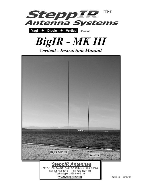
BigIR - MK III<br />
Vertical - Instruction Manual<br />
Dipole<br />
�<br />
Vertical<br />
BigIR MK III<br />
SmallIR<br />
<strong>SteppIR</strong> <strong>Antennas</strong><br />
2112 -116th Ave NE, Suite 2-5, Bellevue, WA 98004<br />
Tel: 425-453-1910 Fax: 425-462-4415<br />
Tech Support: 425-891-6134<br />
www.steppir.com<br />
Revision 02/22/08
<strong>SteppIR</strong> - Why Compromise?<br />
The <strong>SteppIR</strong> antenna was originally conceived to solve the problem of covering the six ham<br />
bands (20m, 17m, 15m, 12m, 10m and 6m) on one tower without the performance sacrifices<br />
caused by interaction between all of the required antennas.<br />
Yagis are available that cover 20 meters through 10 meters by using interlaced elements or<br />
traps, but do so at the expense of significant performance reduction in gain and front to back<br />
ratios. With the addition of the WARC bands on 17m and 12m, the use of interlaced elements<br />
and traps has clearly been an exercise in diminishing returns.<br />
Obviously, an antenna that is precisely adjustable in length while in the air would solve the frequency<br />
problem, and in addition would have vastly improved performance over existing fixed<br />
length yagis. The ability to tune the antenna to a specific frequency, without regard for bandwidth,<br />
results in excellent gain and front to back at every frequency.<br />
The <strong>SteppIR</strong> design was made possible by the convergence of determination and high tech<br />
materials. The availability of new lightweight glass fiber composites, Teflon blended thermoplastics,<br />
high conductivity copper-beryllium and extremely reliable stepper motors has allowed<br />
the <strong>SteppIR</strong> to be a commercially feasible product.<br />
The current and future <strong>SteppIR</strong> products should produce the most potent single tower antenna<br />
systems ever seen in Amateur Radio! We thank you for using our <strong>SteppIR</strong> antenna for your<br />
ham radio endeavors.<br />
Warm Regards,<br />
Mike Mertel<br />
Michael (Mike) Mertel - K7IR<br />
President<br />
<strong>SteppIR</strong> <strong>Antennas</strong> - BigIR 2
<strong>SteppIR</strong> <strong>Antennas</strong> - BigIR 3<br />
<strong>SteppIR</strong> Design<br />
Currently, most multi-band antennas use traps, log cells or interlaced elements as a means to cover several<br />
frequency bands. All of these methods have one thing in common–they significantly compromise<br />
performance. The <strong>SteppIR</strong> antenna system is our answer to the problem. Resonant antennas must<br />
be made a specific length to operate optimally on a given frequency.<br />
So, instead of trying to “trick” the antenna into thinking it is a different length, or simply adding more<br />
elements that may destructively interact, why not just change the antenna length? Optimal performance<br />
is then possible on all frequencies with a lightweight, compact antenna. Also, since the <strong>SteppIR</strong><br />
can control the element lengths, a long boom is not needed to achieve near optimum gain and front to<br />
back ratios on 20 - 10 meters.<br />
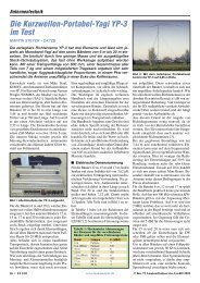
Each antenna element consists of two spools of flat copper-beryllium tape conductor (.54” Wide<br />
x .008” Thick) mounted in the element housing unit. The copper-beryllium tape is perforated to allow<br />
a stepper motor to drive them simultaneously with sprockets. Stepper motors are well known for their<br />
ability to index very accurately, thus giving very precise control of each element length. In addition,<br />
the motors are brushless and provide extremely long service life.<br />
Copper-Beryllium Tape<br />
The copper-beryllium tape is driven out into a hollow fiberglass elements support tube (see below),<br />
forming an element of any desired length up to the limit of each specific antenna model (a vertical uses<br />
only one side). The fiberglass elements support tubes (poles) are telescoping, lightweight and very durable.<br />
When fully collapsed, each one measures approximately 48” in length. Depending on the<br />
model, their may be additional extensions added to increase the overall element length.<br />
The ability to completely retract the copper-beryllium antenna elements, coupled with the collapsible<br />
fiberglass poles makes the entire system easy to disassemble and transport.<br />
The antenna is connected to a microprocessor-based controller (via 22 gauge conductor cable)<br />
that offers numerous functions including dedicated buttons for each ham band, continuous<br />
frequency selection from 40m to 6m (depending on the model). There are also 17 ham and 6<br />
non-ham band memories and you can select a 180° direction reversal* or bi-directional*<br />
mode and it will adjust in just about 3 seconds (* yagi only).<br />
Boom<br />
Element Support Tube Stepper Drive Motor Copper Beryllium Tape<br />
Unit Housing Element
Topic<br />
<strong>SteppIR</strong> <strong>Antennas</strong> - BigIR 4<br />
Table of Contents<br />
<strong>SteppIR</strong> - Why Compromise ? 2<br />
<strong>SteppIR</strong> Design 3<br />
Table of Contents 4<br />
BigIR vertical components 5<br />
Installing the BigIR 5<br />
Prepare the Telescoping Fiberglass Element Support Tubes 8<br />
Installation of the Rain Cap 10<br />
Attach the Telescoping Element Support Tube (pole) to the Element Support Tube<br />
Extensions<br />
Optional (1-1) External Balun 12<br />
Mounting the Antenna (ground) 13<br />
Guy Wire Layouts 14<br />
Installing the 80m Coil to an existing BigIR 15<br />
Radial systems for elevated and ground mounted vertical antennas 16<br />
Using a vertical in or on salt water 20<br />
Control Cable Schematic 21<br />
<strong>SteppIR</strong> Notes 22<br />
<strong>SteppIR</strong> Warranty 23<br />
Page<br />
11
A<br />
E<br />
A<br />
E<br />
B<br />
Glue Kit<br />
<strong>SteppIR</strong> <strong>Antennas</strong> - BigIR 5<br />
D<br />
C<br />
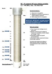
• Lay the element housing unit (EHU), Figure 1 - C, and element support tube extensions<br />
(EST) Figure 1 - A flat on their sides. There will be a 3/4” diameter piece of plastic pipe<br />
protruding out the end of the EST with a coupler attached to it (Figure 5).<br />
• Firmly glue in (using the PVC primer/glue supplied) the 89” section of 3/4” diameter<br />
plastic pipe (Figure 1 - E), that also has a coupler attached to one end.<br />
• Next glue in the second section of 3/4” diameter plastic pipe (Figure 1 - E) with the inside<br />
chamfered ends.<br />
NOTE: If you need to take the antenna apart in the future you can cut the 3/4” diameter<br />
plastic pipe (after homing the copper) a minimum of 1 in. above the coupler and<br />
when you are ready to reinstall the plastic pipe glue in a new coupler.<br />
• Now install the two section of the EST extension tube (Figure 1 - A). The first section<br />
goes firmly onto the EHT tube and the second EST goes on to the end of the first section.<br />
(Figure 7 and Figure 9)<br />
Warning: Be certain that the metal coupler on the extension ESTs firmly bottom out.<br />
Figure 3<br />
Installing the BigIR Vertical<br />
Rubber<br />
Boots<br />
Tape<br />
A: Extension EST’s D: 24” x 1.5” OD Aluminum Mounting Tube<br />
B: 18’ Telescoping Fiberglass Pole E: Diverter Extensions<br />
C: Element Housing Unit (EHU) F: Rain Cap G: Guy Hardware<br />
G<br />
F<br />
Figure 5<br />
Manuals
Figure 7<br />
Figure 9<br />
<strong>SteppIR</strong> <strong>Antennas</strong> - BigIR 6
<strong>SteppIR</strong> <strong>Antennas</strong> - BigIR 7<br />
Prepare the 18 ft Telescoping Fiberglass Element Support Tubes<br />
Locate:<br />
• Dark green fiberglass telescoping poles (Figure 11)<br />
• One black rubber boots with clamps<br />
• One roll of black electrical tape<br />
• One roll of black silicone self-curing tape<br />
• Your tape measure<br />
Note: The black band on the first two pole sections provides extra strength in<br />
potential high wind conditions.<br />
Telescope the pole to full length by pulling each section out firmly in a twisting<br />
motion until it is extended as far as possible. Each segment is tapered and<br />
should lock securely in place when fully extended. The pole must be at least<br />
17 feet 8 inches in length as measured from the butt end of the pole to the tip (Figure<br />
11). Verify the length for the pole before installation or wrapping the joints.<br />
If the pole comes up a little short (1/2” to 1”) try collapsing the pole and starting over,<br />
this time aggressively “jerk” each section out instead of twisting. The pole cannot be<br />
damaged and you may gain a minimum of 1/2” or more. If you have trouble collapsing<br />
the pole try carefully striking one end on a piece of wood or other similar surface<br />
placed on the ground.<br />
At the factory when we quality check the poles to verify that they meet minimum<br />
length we hold the butt (large) end and whip it like we were casting a fishing pole<br />
with considerable force. This procedure can produce a significant difference in the<br />
extended length of some poles as a last resort if nothing else works.<br />
DO BE CAREFUL !!!<br />
Figure 11<br />
17’ 8” min<br />
Rubber Boot<br />
Electrical Tape<br />
Silicone Tape<br />
10’
<strong>SteppIR</strong> <strong>Antennas</strong> - BigIR 8<br />
Warning: Make sure to remove the black rubber plug from the base section of the telescoping element<br />
support tubes (pole). This is a shipping plug for handling convenience and will seriously<br />
damage the copper-beryllium strips and drive mechanisms if not removed.<br />
There is a foam plug glued in the small end of the dark green telescoping pole. This<br />
plug allows the pole to breath preventing the buildup of condensation inside. Do<br />
NOT remove, block, cover, plug, cap or in any way inhibit air flow through this foam<br />
plug filter.<br />
Figure 13 Figure 15<br />
Next wrap each joint on the fiberglass pole with the all weather electrical tape, see Figure 13. Each<br />
joint should have at least the full width of the tape on both sides of the joint.<br />
Exception: On joints with reinforcing rings, the tape must continue further so it extends a minimum<br />
of 3/4” beyond the metal ring and onto the fiberglass pole.<br />
Apply one complete wrap of electrical tape around the fiberglass tube as you begin, and then work<br />
your way across the joint and back using half overlap wraps, so that the entire area is seamlessly covered.<br />
Carefully stretch and smooth the tape with your finger as you apply, and especially when you<br />
change directions - this will help avoid ripples and have the tape lie as smoothly as possible. At the<br />
end of the run, cut the tape with a knife or scissors and press the end onto the pole. Then run your hand<br />
over the tape a couple of times to firm up the bonding.
<strong>SteppIR</strong> <strong>Antennas</strong> - BigIR 9<br />
Recommended Lengths for Silicone Tape Wrapping<br />
A B C<br />
Figure 17<br />
A -<br />
B -<br />
C -<br />
18 in / 46 cm<br />
16 in / 41 cm<br />
11 in / 28 cm<br />
Next, you will weatherproof and UV protect each joint with the black self-curing silicone tape see Figure<br />
15. It is important that you pre-cut the silicone tape to the recommended lengths. If<br />
you do so, you will have more than enough for each joint. Refer to Figure 17 for proper<br />
lengths for each joint. (With the BigIR their will be more than enough tape)<br />
IMPORTANT: Per the manufactures specifications the silicone tape has a shelf life of 12<br />
months before it is used and should be stored in a cool dry environment. Silicone tape<br />
will not stick to just any surface. It only bonds to itself. Be sure to remove all the<br />
connector protector residue from your hands before handling silicone tape, as that<br />
residue will cause the silicone wrap not to adhere to itself in places. Take care to keep<br />
the silicone wrap free of dirt or debris. Also, this tape MUST be cut. Do not tear it.<br />
Wash your hands before completing the following steps.<br />
Position the black silicone tape about 1/2” to the right of the black electrical tape and wrap one layer,<br />
continually stretching the silicone tape a minimum of 100 % its original length, completely around the<br />
pole so the tape fully overlaps itself. Then slowly wrap the silicone tape to the left using half overlap<br />
wraps, extending about 1/2” beyond the black electrical tape. When you reach the end, wrap one layer<br />
completely around the pole so the tape fully overlaps itself just as you did at the beginning of the wrap.<br />
If you are stretching the tape correctly you will get about two layers of tape at each joint. As before,<br />
carefully stretch and lay the tape down as smooth as possible. The final joint should look like Figure<br />
15.<br />
Important: After the silicone tape has been applied, be sure to rub each wrap with your hand<br />
several times to ensure that it is flat and has adhered to itself.
<strong>SteppIR</strong> <strong>Antennas</strong> - BigIR 10<br />
Installation of the Rain Cap<br />
On the tip of the pole you will install a black cap (Figure 19) with a piece of tubing passing<br />
through it. The purpose of this vent cap is to keep the rain out, yet still allow air flow through<br />
the foam plug into the telescoping pole.<br />
Warning: Press the cap on approximately 1-1/8” (Figure 20). Do NOT press the cap down so<br />
hard as to crimp (damage) the cross tube preventing the pole from properly venting.<br />
Figure 19<br />
Rain Cap & Vent<br />
Push On<br />
1.125<br />
Figure 20
<strong>SteppIR</strong> <strong>Antennas</strong> - BigIR 11<br />
Attach the Telescoping Element Support Tube (pole) to the Element Support Tube Extensions<br />
NOTE: The pole was tested at the factory prior to shipping, however in the event the pole just won’t<br />
fit sanding it is okay.<br />
Locate the rubber boot.<br />
• Place the narrow end of a rubber boot onto the butt end of the EST (pole). Slide it about 6” out<br />
onto the EST (Figure 21-A).<br />
• Insert the butt end of that EST into the extension tube until the raised black ring is approximately<br />
1/2 in. above the extension tube (Figure 21-B).<br />
• Push the rubber boot firmly onto the extension tube until the screw clamp is past the aluminum ring<br />
and will clamp down onto the fiberglass (Figure 21-C).<br />
• The upper screw clamp should be past the raised black ring to get the proper seal on the telescoping<br />
pole (Figure 21-C).<br />
• Firmly tighten both stainless steel screw clamps. Then test the connection by pulling and twisting<br />
it. There should be no slippage at the joints.<br />
NOTE: You should re-tighten each clamp a second time (at<br />
least 30 minutes after the first time you tightened them)<br />
before raising the antenna to the tower, to be sure that<br />
there has been no cold flowing of the PVC material on<br />
the rubber boot.<br />
A<br />
B<br />
Figure 21<br />
C
Coax<br />
Optional (1-1) External Balun<br />
Note: If you have purchased the optional balun now is a good time to install it.<br />
A balun is an electrical circuit used to help resolve the inherent problem of feeding an antenna<br />
with an electrically unbalanced (coax) feed line. It is intended to present an infinite<br />
impedance to any RF current that might otherwise flow on the outer conductor (shield) of the<br />
coax producing radiation from the line. This current, if high enough, can cause heat buildup<br />
and potential damage to the radio as well as a distorted radiation pattern.<br />
Balun Installation<br />
To install the balun (Figure 25) we suggest that you<br />
mount it as shown in Figure 27. There are two holes<br />
in the base of the balun that will line up with two<br />
screws in the end of the element housing unit next to<br />
the SO-239 connector. Remove these two screws and<br />
reinstall them through the balun then connect the PL-<br />
259 as shown in Figure 27. Your feed line will then<br />
plug into the SO-239 in the center of the balun.<br />
Figure 25<br />
<strong>SteppIR</strong> <strong>Antennas</strong> - BigIR 12<br />
Ferrite<br />
Toroidal<br />
Core<br />
Radio<br />
Antenna<br />
Figure 23<br />
Optional External Balun<br />
Why is it Optional ?:<br />
In the normal configuration, ground mounted<br />
with 12 or more radials, the ground will bleed/<br />
drain the unwanted RF signal from the coax<br />
shield.<br />
When Should You Use A Balun ?:<br />
• When elevating the base of a vertical<br />
antenna above the ground<br />
• When only a few radials are used<br />
• When the coax run is shorter than the radials<br />
• When the ground condition is poor<br />
• Unusual SWR readings on one band<br />
Figure 27<br />
Balun Mounted on BigIR
<strong>SteppIR</strong> <strong>Antennas</strong> - BigIR 13<br />
Mounting the Antenna (ground)<br />
The BigIR comes with a 1.5” OD aluminum mounting post, 2 feet in length (Figure 1 - D). If<br />
using guy wires, the antenna can be mounted directly into the ground without concrete (the guy<br />
wires will “lock” the antenna in place) but you want to ensure that the mounting pole does not<br />
shift or settle over time, using concrete to secure it in the ground is a good way to eliminate the<br />
potential for this problem. Position the mounting pole (machined end up) so that the bottom of<br />
the element housing is 8 to 10 inches above the ground (Figure 29).<br />
At this point you want to decide on your guy configuration and mount the guy bracket (s) and<br />
attach the guy wires before erecting the antenna (Figure 35, 36 & 37).<br />
• No Guy Wires 70 mph<br />
• One set of guy wires 90 mph<br />
• Two sets of guy wires (optional bracket) 110 mph<br />
• High wind guy set (optional complete kit) 125 mph<br />
• Anchor radius for guys = 11 ft minimum<br />
One guy wire connects to one side of the guy bracket and two guy wires connect to the other<br />
side of the guy bracket using the two security snaps (Figure 31).<br />
With the mounting post is in place and level and your guy assembly mounted, you are ready to<br />
erect the antenna. Now slide the small end of the flexible coupler (rubber boot) to the mounting<br />
post (Figure 41). This coupler is used to keep the antenna from potentially “twisting” in high<br />
winds. Pick up the antenna at the base (Figure 33) and slide the antenna housing onto the<br />
mounting pole until it firmly bottoms out. Place the larger end of the flexible coupler over the<br />
antenna housing tube (a small amount of bar soap or other lubricant will help the process).<br />
Tighten clamps on the coupler and secure the guy wires.<br />
Now you are ready to connect the radials! We recommend<br />
using a lug connector (crimped & soldered) at the end of<br />
your radials, and then tightening the lug onto the connector Ground Radials (4 - 16’ - 16 ga wires)<br />
(ground) post shown in Figure 39. If you purchased the op-<br />
Figure 28<br />
tional radial kits (Figure 28), you will notice there are 4<br />
wires per set (ground radials), all soldered and crimped to a lug connector.<br />
EHU<br />
Figure 29<br />
8 to 10 in.<br />
Guy Wires (3)<br />
Security<br />
Snap (2)<br />
Figure 31<br />
Figure 33
Ground Mounting:<br />
<strong>SteppIR</strong> <strong>Antennas</strong> - BigIR 14<br />
Recommended Radials<br />
• Min. of 8 - 16 foot radials<br />
Elevated Mounting:<br />
Figure 35<br />
Anchor<br />
Figure 39<br />
Anchor<br />
Antenna<br />
• Min. of 2 pre band trimmed to .1 x frequency<br />
Anchor<br />
Single Guy<br />
Configuration Figure 37 Double Guy<br />
Configuration<br />
Guy @ 11ft<br />
Above Ground<br />
Bracket (Supplied)<br />
Warning:<br />
A 11 ft radius and an even spread (120<br />
deg) are the minimum dimensions required,<br />
when positioning the guy anchors,<br />
to achieve the stated wind ratings<br />
Ground<br />
Second Guy @ 15ft<br />
Above Ground<br />
Bracket (optional)<br />
Figure 36<br />
First Guy @ 7.5ft<br />
Above Ground<br />
Bracket (Supplied)<br />
Mounting<br />
Tube<br />
Flexible<br />
Coupler<br />
Figure 41<br />
Figure 43<br />
8 to in. 10
<strong>SteppIR</strong> <strong>Antennas</strong> - BigIR 15<br />
Installing the 80m Coil to an existing BigIR<br />
The 80m coil back plate will have 4 of its 8 holes that will align with 4 of the holes in your<br />
element housing unit (EHU).<br />
Remove the 4 bolts already in these 4 holes.<br />
Install the new bolts, spacers and coil to your element housing and tighten the new Nylok<br />
nuts as shown in (Figure 45 & Figure 47).<br />
4 SS bolts with<br />
Nylok nuts<br />
Figure 45<br />
4 Nylon Spacers<br />
Figure 47
<strong>SteppIR</strong> <strong>Antennas</strong> - BigIR 16<br />
All vertical monopoles need some form of counterpoise in which antenna image currents flow<br />
to work efficiently. This counterpoise usually consists of a system of radial wires placed either<br />
on the ground or elevated above ground.<br />
This is not an in depth publication but simply a general guide on installing and using the <strong>SteppIR</strong><br />
verticals. There is much more information available in various publications if you need it.<br />
The ARRL Antenna Handbook is a good source for additional information.<br />
By following a few simple guidelines, you can obtain excellent performance from vertical antennas<br />
mounted on the ground or elevated above the ground. There are a number of verticals<br />
available that say “no radials required”, but they do have “radials”, in the form of a shortened,<br />
tuned counterpoise system. As you might expect, you pay a price for such a small counterpoise<br />
system - less efficiency.<br />
As you will see in the following pages, you can get fairly high efficiency with a relatively modest<br />
radial system that will far outperform small counterpoise systems. It should be noted that<br />
counterpoise systems are only good for curing near field losses caused by losses from the earth,<br />
which is a poor conductor of RF, even with good soil. There is nothing you can do about far<br />
field losses that reduce the signal strength and low angle radiation, except get to some saltwater.<br />
We briefly discuss salt water locations later on in this article.<br />
PROS<br />
Ground Mount or Elevate?<br />
Ground Mounting:<br />
• The radials can be any length and they work<br />
on all frequencies<br />
• Easy to mount<br />
• Easy access<br />
• Lower visual profile<br />
• Eight to twelve 0.1 wavelength radials gives<br />
60% - 65% efficiency (one set of 8 - 12 radials<br />
cut to 0.1 wavelength at lowest frequency)<br />
CONS<br />
• Takes 120 radials to equal an elevated<br />
vertical with 2 resonant radials (90% efficient)<br />
• Surrounding objects can reduce signal<br />
strength
<strong>SteppIR</strong> <strong>Antennas</strong> - BigIR 17<br />
PROS<br />
• + 90% efficient with two wavelength�<br />
.25<br />
radials<br />
• Antenna is generally more “in the clear”,<br />
so surrounding objects don’t cause as<br />
much attenuation<br />
• A peaked metal roof will make a very good<br />
all-frequency radial system<br />
Elevated Mounting:<br />
Ground Mounting:<br />
CONS<br />
• Requires two .25 wavelength radials for<br />
each band of operation (radials interact, so<br />
spacing will affect length)<br />
• Mounting is generally more involved<br />
• Visually higher profile<br />
• Must be mounted high enough that people<br />
won’t walk into it<br />
• Needs to be about .2 wavelengths high to<br />
get an ideal 50 ohm match<br />
• Radials need at least a 20° slope to get a<br />
good match<br />
• Involves adjusting and fine tuning the radial<br />
lengths<br />
If you chose to ground mount the vertical, pick a spot that will allow you the best chance of<br />
spreading your radials evenly around the antenna, and away from trees and other objects if possible.<br />
Mount the antenna within one foot of ground if possible, the closer to ground the better.<br />
Next, you will need to determine how much effort and wire you are willing to invest in this installation.<br />
The tradeoffs are as follows:<br />
1. More radials equals higher efficiency (see Graph 1)<br />
2. More short radials are generally better than a few long ones<br />
3. If only a few radials are going to be used, they need not be very long<br />
4. If you have very good earth (very few of us actually do), you can obtain good performance<br />
with very few radials.<br />
Graph 1<br />
% Efficiency<br />
100<br />
80<br />
60<br />
40<br />
20<br />
0<br />
0 15 30 45 60 75 90 105 120<br />
Number of Radials<br />
Number of radials
Four radials are what we consider to be the absolute minimum in average soil. How much you<br />
have to gain with a good radial system depends on how good your earth is. Most of us have<br />
poor earth conditions, so the radial system is important. The worse the earth is, the more can<br />
be gained with radials. Graph 2 shows a graph produced by Brian Edward (N2MF) that illustrates<br />
the relative signal gain you get with the radials and varying length over poor earth. With<br />
better earth, the gain difference between 4 radials and 120 radials will be about 2.5 dB, as opposed<br />
to 4 dB with poor earth.<br />
Graph 2<br />
<strong>SteppIR</strong> <strong>Antennas</strong> - BigIR 18<br />
If you are restricted to .1 wavelength radials there is not much advantage to using more than<br />
about 24 radials. You can see from Graph 3 that if more radials are used there is a huge advantage<br />
to making them longer.<br />
If you cannot lay the radials out in a symmetrical radial pattern, don’t worry too much - it will<br />
distort your omni-directional pattern slightly but won’t reduce your efficiency very much. Lay<br />
the radials out in the best manner possible given your situation. There are various ways to accomplish<br />
laying a radial system, including turning corners, etc. Good results are limited only to<br />
your creative energy and determination! Be aware that very high voltages can exist at the ends<br />
of radials, so be certain that no one can come into contact with them. It is a good idea to use<br />
insulated wire to protect from corrosion, and don’t bury the radials any deeper than necessary,<br />
one to three inches is sufficient.<br />
Graph 3<br />
Relative Gain<br />
3.6<br />
3<br />
2.4<br />
1.8<br />
1.2<br />
0.6<br />
0<br />
-0.6<br />
-1.2<br />
0 0.06 0.12 0.18 0.24 0.3 0.36 0.42 0.48 0.54 0.6<br />
Sufficient Radial Length (wavelength)<br />
0.48<br />
0.4<br />
0.32<br />
0.24<br />
0.16<br />
0.08<br />
Radil Length in Wave length<br />
N=120<br />
0<br />
0 15 30 45 60 75 90 105 120<br />
N=48<br />
N=24<br />
N=12<br />
N=4<br />
Radial length in wavelength<br />
Number of Radials (N)<br />
Number of radials<br />
N=96<br />
120 Radials<br />
96 Radials<br />
48 Radials<br />
24 Radials<br />
12 Radials<br />
4 Radials
<strong>SteppIR</strong> <strong>Antennas</strong> - BigIR 19<br />
Elevated Mounting:<br />
You can elevate a vertical just a few feet from the ground (4 feet for 20m, 8 feet for 40m) and<br />
get fairly good performance with just 2 radials (elevated as well) per band of operation. The<br />
problem is you won’t have a very good match to 50 ohms, and the close proximity of the earth<br />
will degrade the signal - especially if it is poor earth. For ideal matching, we recommend .2<br />
wavelength (about 15 feet on 20m and 30 feet on 40m) at the lowest planned frequency of operation<br />
As the height decreases below .2 wavelength, the ground losses start to increase, unless<br />
you have very good ground. When a vertical is raised off the ground the impedance drops fairly<br />
rapidly from 36 ohms (Over perfect ground or with many radials it will be close to 36 ohms,<br />
over real ground it is generally 40– 60 ohms) to about 22 ohms when .3 wavelength is reached.<br />
This would make a pretty poor match to 50 ohms, so a couple of tricks are in order. Once you<br />
elevate a vertical, two radials are all you really need. It is important that you try to keep a 180°<br />
angle between the two (opposed, directly in line) for the best pattern. Spread the radials out as<br />
far as possible to reduce interaction, if they are less than a foot apart it can be difficult to get a<br />
good match on all bands. To facilitate a match to 50 ohms you can angle the radials downward,<br />
this raises the impedance of the antenna as you increase the angle downward. Graph 4 shows<br />
the approximate relationship of radial angle to impedance:<br />
Graph 4<br />
Radial Droop Angle Antenna Impedance<br />
0° = 22 Ohms<br />
10° = 28 ohms<br />
20° = 35 ohms<br />
30° = 47 ohms<br />
40° = 53 ohms<br />
50° = 55 ohms<br />
Note: above 50° results in diminishing returns
<strong>SteppIR</strong> <strong>Antennas</strong> - BigIR 20<br />
Can’t get enough droop angle to achieve a good match? Simply adjust the antenna element<br />
slightly longer than the factory 1/4 wavelength (up to 20% longer) settings and the impedance<br />
will rise. This will cause the radials to be too long, so they may need to be pruned a bit. Be<br />
aware that increasing the antenna 2% to 3% longer may require radials to be 5% to 7% shorter.<br />
Once you have a good match, replace the factory default values by saving the new antenna (to<br />
do this you will use the “create, modify” feature in the setup mode).<br />
When the vertical is elevated you can get away with just one resonant radial, however, the pattern<br />
won’t be omni-directional. You will have -12 dB to 15 dB null in one direction<br />
Using a Vertical in on or Near Salt Water:<br />
If you are lucky enough to have a dock over salt water, a vertical can offer unparalleled performance<br />
for low angle DX. Simply mount the vertical to the dock and attach two radials per<br />
band of operation. They can be stapled right to the dock if it is non-metallic. Mounting the<br />
vertical in ground flooded by salt water a couple of times per day can be equally effective.<br />
Proximity to the ocean improves the far field loss of a vertical and allows very low angle radiation<br />
- get as close to the water as possible to enhance performance.<br />
Due to the fact that RF does not penetrate more than 2 inches into the water, direct coupling (a<br />
wire in the water) is difficult. Objects like metal floats or boats, providing they are large<br />
enough, can make good grounds in salt water. If you are using a metal boat or large metal object,<br />
corrosion is no longer a problem because the large surface capacitively couples to the water.<br />
When using a small metal float (3 ft x 3 ft is just enough to “connect” to salt water), you<br />
want to be certain that the metal does not corrode over time. For long term immersion, Monel<br />
is a good (but fairly expensive ) choice.
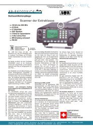
CoilAntena<br />
1<br />
13<br />
234567891012<br />
1415161718192021232425Solder Side of the Plug<br />
<strong>SteppIR</strong> <strong>Antennas</strong> - BigIR 21<br />
Solder Drain to<br />
Conector Case<br />
Male 25 Pin Dsub.<br />
5678 1234<br />
4 Pin Weather Prof Plug<br />
Drain BlackRedGrenWhite BlackRedGrenWhite Solder<br />
4 Conductor<br />
To the Antenna<br />
4 Conductor with lugs<br />
to the Optional 80M coil<br />
(If Ordered)<br />
Asemble over cable before soldering (to antena only)<br />
Shield<br />
2 3 4 1 2 1 3 4 pin pinout viewed<br />
from the solder side Black Red GrenWhite<br />
4<br />
Warning: A miswired cable can<br />
damage the controller.<br />
(2) - 4 Conductor Cables<br />
(BigIR + 80m Coil to Controller)<br />
Drawing 1
<strong>SteppIR</strong> <strong>Antennas</strong> - BigIR 22
<strong>SteppIR</strong> <strong>Antennas</strong> - BigIR 23<br />
www.steppir.com<br />
L i m i t e d W a r r a n t y<br />
These products have a limited warranty against manufacturer's<br />
defects in materials or construction for two (2) years from date of<br />
sale. Do not modify this product or change physical construction<br />
without the written permission of <strong>SteppIR</strong> <strong>Antennas</strong> Inc. This<br />
limited warranty is automatically void if the following occurs:<br />
improper installation, unauthorized modifications, physical abuse or<br />
damage from severe weather, beyond the manufacturer's control.<br />
Manufacturer's responsibility is strictly limited to repair, or<br />
replacement of defective components. The shipping instructions<br />
will be issued to the buyer for defective components, and shipping<br />
charges will be paid for by the buyer to the manufacturer. The<br />
manufacturer assumes no further liability.
Yagi �<br />
Dipole<br />
�<br />
www.steppir.com<br />
Vertical<br />
<strong>SteppIR</strong> Antenna Information Web Sites(as of 4/09/07)<br />
http://steppir.com/<br />
http://groups.yahoo.com/group/steppir/