
You also want an ePaper? Increase the reach of your titles
YUMPU automatically turns print PDFs into web optimized ePapers that Google loves.
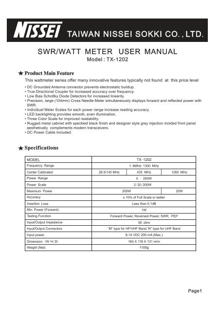
TAIWAN NISSEI SOKKI CO LTD<br />
SWR SWR/ / WATT METER USER <strong>MANUAL</strong><br />
Product Main Feature<br />
Model : <strong>TX</strong>-<strong>1202</strong><br />
., .<br />
This wattmeter series offer many innovative features typically not found at this price level<br />
DC Grounded Antenna connector prevents electrostatic buildup.<br />
True Directional Coupler for increased accuracy over frequency.<br />
Low Bias Schottky Diode Detectors for increased linearity.<br />
Precision, large (104mm) Cross Needle Meter simultaneously displays forward and reflected power with<br />
SWR.<br />
Individual Meter Scales for each power range increase reading accuracy.<br />
LED backlighting provides smooth, even illumination.<br />
Three Color Scale for improved readability.<br />
Rugged metal cabinet with speckled black finish and designer style grey injection molded front panel<br />
aesthetically complements modern transceivers.<br />
DC Power Cable Included.<br />
Specifications<br />
MODEL<br />
Frequency Range<br />
Power Range<br />
Power Scale<br />
Maximum Power<br />
Accuracy<br />
Insertion Loss<br />
Min. Power (Forward)<br />
Testing Function<br />
Input/Output Impedance<br />
Input/Output Connectors<br />
Input power<br />
Dimension ( W/ H/ D)<br />
Weight (Net)<br />
<strong>TX</strong>-<strong>1202</strong> 1. 6MHz-1300 MHz<br />
Center Calibrated 28.5/145 MHz 435 MHz<br />
1260 MHz<br />
200W<br />
0 - 200W<br />
2/ 20/ 200W<br />
± 10% of Full Scale or better<br />
Less than 0.1dB<br />
1W<br />
Forward Power, Reversed Power, SWR, PEP<br />
50 ohm<br />
“M” type for HF/VHF Band, “ N” type for UHF Band<br />
9-14 VDC 200 mA (Max.)<br />
184 X 118 X 131 m/m<br />
1100g<br />
20W<br />
Page1
Front Panel<br />
Rear Panel<br />
9<br />
1 2<br />
6<br />
PEP<br />
LED OFF<br />
7<br />
8<br />
AVG<br />
ON<br />
5<br />
UHF<br />
HF 70cm UHF<br />
VHF<br />
25cm<br />
Forward /Reverse Pwr /SWR Measurement<br />
Caution<br />
10<br />
100<br />
3<br />
4<br />
<br />
A. Set the RANGE switch to the proper meter multiplier (X1, X10, X100) for the<br />
expected power level of the intended measurement.<br />
B. In <strong>TX</strong>-<strong>1202</strong>, it corrosponds to 2/20/200 watts forward and 0.5/5/50 watts<br />
reflected full scale (Fwd : Ref =4:1)<br />
C. Select the frequency needed (HF/VHF/UHF amateur bands)<br />
D. Set the radio transceiver to transmit mode and read the scale corresponding<br />
to the RANGE selected<br />
E. When switch to 'AVG', the meter reads average RF power.When switch to<br />
'PEP', the meter reads Peak Envelope Power for use withSSB and AM<br />
transmissions. In this mode, there will be a slow rise and decay time.<br />
F. Push LED ON/OFF button when LED light is needed<br />
1. Indicator Display : Indicates FWD/REV power in watts and VSWR ratio<br />
2. AVG/PEP (elliptical) push botton : Select AVG (out) or PEP (depressed)<br />
3. Frequency switch : Select frequency measured<br />
4. Range switch : Selects RF power range multiplier x1 x10 x100<br />
5.LED ON/OFF button (elliptical) : Turn LED lamp<br />
6. Zero adjust screws of analog cross needle meter<br />
<br />
7. <strong>TX</strong> connector : Coax connector to transmitter 50 ohm RF output<br />
8. ANT connector : Coax connector to 50 ohm antenna system<br />
9.13.8V DC connection (via power supply) : LED illumination<br />
Note1:Watch out the LED wire must be correctly connected, black/<br />
white to '+', Black to '-'. Wrong connection burn LED)<br />
Note2:DCpower is only required to run the meter backlight. This<br />
meter will function w/o DC power in the AVG mode, even when<br />
switch off.<br />
<br />
1. Since the meter movement is very sensitive, avoid excessive vibration or mechanical shock to the meter.<br />
2. Watch the absolute maximum power could be applied to the meter by different models you bought.<br />
3. The meter must never be reverse connected. Always observe the correct connections to transmitter and<br />
antenna as indicated on the rear sockets.<br />
4. Do not expose the meter to excessive temperatures, high humidity, or strong magnetic fields.<br />
5. Contact your local dealer for service. Dealer information is in the back of user manual.<br />
RoHS<br />
12V DC<br />
Page2