
Create successful ePaper yourself
Turn your PDF publications into a flip-book with our unique Google optimized e-Paper software.
AT0722 1/5/2007<br />
NL ES FR UK SK CZ DE Export BE<br />
Tel. : +32 15 21 50 21<br />
Fax : +32 15 21 82 35<br />
dme_benelux@dmeeu.com<br />
Tel. : +32 15 21 50 17<br />
Fax : +32 15 40 51 17<br />
dme_export@dmeeu.com<br />
Tel. : +49 (0)2351 437 0<br />
0180 500 4846<br />
Fax : +49 (0)2351 437 220<br />
0180 500 4845<br />
dme_normalien@dmeeu.com<br />
Tel.: (0)800 142 451<br />
Fax: (0)800 142 450<br />
dme_cz@dmeeu.com<br />
Tel.: +420 571 616 320<br />
Fax: +420 571 611 996<br />
dme_cz@dmeeu.com<br />
Tel.: +44 2071 3300 37<br />
Fax: +44 2071 3300 36<br />
dme_uk@dmeeu.com<br />
Tel.: +33 1 49 93 92 23<br />
Fax: +33 1 49 93 92 22<br />
dme_france@dmeeu.com<br />
Tel.: +34 93 338 7794 or 7952<br />
Fax: +34 93 261 1828<br />
expulsores_girona@dmeeu.com<br />
Tel. : +31 (0)2065 45 571<br />
Fax : +31 (0)2065 45 572<br />
dme_benelux@dmeeu.com<br />
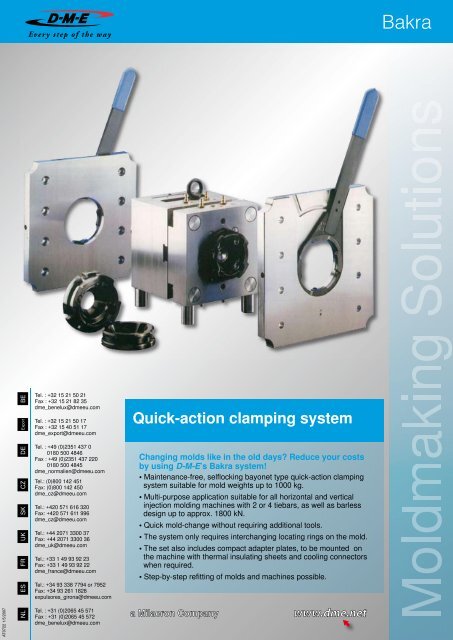
<strong>Quick</strong>-<strong>action</strong> <strong>clamping</strong> <strong>system</strong><br />
Changing molds like in the old days? Reduce your costs<br />
by using D-M-E’s Bakra <strong>system</strong>!<br />
• Maintenance-free, selflocking bayonet type quick-<strong>action</strong> <strong>clamping</strong><br />
<strong>system</strong> suitable for mold weights up to 1000 kg.<br />
• Multi-purpose application suitable for all horizontal and vertical<br />
injection molding machines with 2 or 4 tiebars, as well as barless<br />
design up to approx. 1800 kN.<br />
• <strong>Quick</strong> mold-change without requiring additional tools.<br />
• The <strong>system</strong> only requires interchanging locating rings on the mold.<br />
• The set also includes compact adapter plates, to be mounted on<br />
the machine with thermal insulating sheets and cooling connectors<br />
when required.<br />
• Step-by-step refitting of molds and machines possible.<br />
Bakra<br />
Moldmaking Solutions
Part List<br />
1 Mold Clamping Plate<br />
2 Locating Ring<br />
3 SHC-screw<br />
4 SHC-screw<br />
4<br />
1 2 3<br />
5 Adapter Plate<br />
6 Wrench<br />
7 Locking Ring<br />
8 Thermal Insulating Sheet<br />
Cost-efficiency comparison for mold-change on a 1000 kN<br />
injection molding machine.<br />
Clamp DIN 6316<br />
and <strong>clamping</strong> screw<br />
Bakra<br />
No. of mold changes / year 150 150<br />
No. of operators / change 2 1<br />
9<br />
10<br />
5 6 7 8<br />
9 Retention Pin<br />
10 Spring Loaded Set screw<br />
Hours required / change 2 x (0,5 h (= 30 Min.)) 0,083 h (= 5 Min)<br />
Purchase costs / 5-year depreciation € 400 ( € 80 / a) € 3800 ( € 760 / a)<br />
Wages / year (€ 41 / h person) € 6150 € 512,50<br />
Machine down times / year (€ 51 / h) € 3825 € 637,50<br />
Costs / year € 10055 € 1910<br />
Savings / year 81%<br />
The complete set contains<br />
the following items:<br />
2 Adapter plates (BS/FS)<br />
2 Locking rings (BS/FS)<br />
1 Wrench<br />
2 Locating rings (BS/FS)<br />
Please specify type of molding machine.<br />
Insulating scheets upon request.<br />
Screws are included.<br />
www.dme.net<br />
BS FS<br />
BS = moveable half<br />
FS = fixed half<br />
H = rear *<br />
O = top*<br />
V = front*<br />
* Please specify side of locking <strong>system</strong>
AD<br />
Adapter plates<br />
Mat.: 1.2312<br />
BS and FS are mirror-inverted<br />
REF d l x b s<br />
AD 110 218 x 246 22<br />
AD 110 246 x 246 22<br />
AD 110 246 x 296 22<br />
AD 110 265 x 396 22<br />
AD 110 280 x 400 22<br />
AD 110 296 x 296 22<br />
AD 110 296 x 346 22<br />
AD 110 346 x 346 22<br />
AD 110 346 x 396 22<br />
AD 110 396 x 396 22<br />
AD 110 396 x 646 22<br />
AD 110 400 x 450 22<br />
AD 110 410 x 410 22<br />
SP<br />
Locking rings<br />
Mat.: 1.2312 ~ 1030 N/mm 2<br />
BS and FS are mirror-inverted<br />
REF d Type<br />
SP 110 BS*<br />
SP 110 FS*<br />
SP 125 BS*<br />
SP 125 FS*<br />
*BS = moveable half<br />
*FS = fixed half<br />
SPS<br />
Wrench<br />
Mat.: St 50<br />
When ordering please specify:<br />
Flange dia., size of adapter<br />
plate, wrench opening, Type of<br />
molding machine.<br />
REF d l x b s<br />
AD 110 410 x 446 22<br />
AD 110 446 x 446 22<br />
AD 110 496 x 496 22<br />
AD 110 496 x 546 22<br />
AD 110 520 x 520 22<br />
AD 110 530 x 530 22<br />
AD 110 546 x 596 22<br />
AD 110 580 x 580 22<br />
AD 110 596 x596 22<br />
AD 110 596 x 646 22<br />
AD 110 646 x 646 22<br />
AD 110 646 x 696 22<br />
AD 110 696 x 696 22<br />
REF d l x b s<br />
AD 125 218 x 246 27<br />
AD 125 246 x 246 27<br />
AD 125 246 x 296 27<br />
AD 125 265 x 396 27<br />
AD 125 280 x 400 27<br />
AD 125 296 x 296 27<br />
AD 125 296 x 346 27<br />
AD 125 346 x 346 27<br />
AD 125 346 x 396 27<br />
AD 125 396 x 396 27<br />
AD 125 396 x 646 27<br />
AD 125 400 x 450 27<br />
AD 125 410 x 410 27<br />
Mold safety device is available as option.<br />
REF d l x b s<br />
AD 125 410 x 446 27<br />
AD 125 446 x 446 27<br />
AD 125 496 x 496 27<br />
AD 125 496 x 546 27<br />
AD 125 520 x 520 27<br />
AD 125 530 x 530 27<br />
AD 125 546 x 596 27<br />
AD 125 580 x 580 27<br />
AD 125 596 x 596 27<br />
AD 125 596 x 646 27<br />
AD 125 646 x 646 27<br />
AD 125 646 x 696 27<br />
AD 125 696 x 696 27
ZV<br />
Centering Device<br />
Mat.: 1.1730<br />
MAP = Machine plate<br />
REF d x d1<br />
ZV 110 x 60<br />
ZV 110 x 80<br />
ZV 110 x 90<br />
ZV 110 x 100<br />
ZV 110 x 110<br />
ZV 110 x 125<br />
ZV 110 x 160<br />
ZV 110 x 175<br />
ZV 125 x 60<br />
ZV 125 x 80<br />
ZV 125 x 90<br />
ZV 125 x 100<br />
ZV 125 x 110<br />
ZV 125 x 125<br />
ZV 125 x 160<br />
ZV 125 x 175<br />
WP<br />
Thermal Insulating sheets<br />
Thermal conductivity λ: 0,2 W/mK<br />
T max: 200°C<br />
Compressive strength (20°C): 600 N/mm 2<br />
Screw holes and recesses for tiebars will be<br />
provided according to your drawing.<br />
REF d l x b<br />
WP 110 218 x 246<br />
WP 110 246 x 246<br />
WP 110 246 x 296<br />
WP 110 265 x 396<br />
WP 110 280 x 400<br />
WP 110 296 x 296<br />
WP 110 296 x 346<br />
WP 110 346 x 346<br />
WP 110 346 x 396<br />
WP 110 396 x 396<br />
WP 110 396 x 646<br />
WP 110 400 x 450<br />
WP 110 410 x 410<br />
REF d l x b s<br />
WP 110 410 x 446<br />
WP 110 446 x 446<br />
WP 110 496 x 496<br />
WP 110 496 x 546<br />
WP 110 520 x 520<br />
WP 110 530 x 530<br />
WP 110 546 x 596<br />
WP 110 580 x 580<br />
WP 110 596 x596<br />
WP 110 596 x 646<br />
WP 110 646 x 646<br />
WP 110 646 x 696<br />
WP 110 696 x 696<br />
REF d l x b s<br />
WP 125 218 x 246<br />
WP 125 246 x 246<br />
WP 125 246 x 296<br />
WP 125 265 x 396<br />
WP 125 280 x 400<br />
WP 125 296 x 296<br />
WP 125 296 x 346<br />
WP 125 346 x 346<br />
WP 125 346 x 396<br />
WP 125 396 x 396<br />
WP 125 396 x 646<br />
WP 125 400 x 450<br />
WP 125 410 x 410<br />
Bakra<br />
REF d l x b s<br />
WP 125 410 x 446<br />
WP 125 446 x 446<br />
WP 125 496 x 496<br />
WP 125 496 x 546<br />
WP 125 520 x 520<br />
WP 125 530 x 530<br />
WP 125 546 x 596<br />
WP 125 580 x 580<br />
WP 125 596 x 596<br />
WP 125 596 x 646<br />
WP 125 646 x 646<br />
WP 125 646 x 696<br />
WP 125 696 x 696
ZF ...<br />
Locating rings<br />
Mat.: 1.2312 ~ 1030 N/mm 2<br />
ZF 110 ZF 125<br />
Moveable half (BS) Fixed half (FS) Moveable half (BS) Fixed half (FS)<br />
ZF 110/BS/3<br />
4 x Ø 10<br />
ZF 110/BS/4<br />
4 x Ø 10<br />
ZF 110/FS/3<br />
4 x Ø 10<br />
ZF 110/BS/5 ZF 110/FS/6<br />
ZF 110/BS/7<br />
6 x Ø 8<br />
ZF 110/BS/8<br />
6 x Ø 8<br />
ZF 110/BS/10<br />
6 x Ø 8 / 4 x Ø 10,5<br />
ZF 110/BS/16<br />
4 x Ø 10<br />
www.dme.net<br />
Ø90<br />
Ø76<br />
Ø90<br />
Ø76<br />
Ø90<br />
Ø90<br />
Ø80<br />
Ø90<br />
Ø80<br />
Ø110<br />
Ø80<br />
Ø90<br />
Ø80<br />
Ø19<br />
Ø52<br />
Ø52<br />
Ø52<br />
Ø25<br />
60<br />
Ø45<br />
ZF 125/BS/1<br />
4 x Ø 12<br />
ZF 125/FS/1<br />
4 x Ø 12<br />
ZF 110/FS/4 ZF 125/BS/2 ZF 125/FS/2<br />
6 x Ø 8<br />
ZF 110/FS/8<br />
4 x Ø 10<br />
ZF 110/FS/9<br />
4 x Ø 10<br />
ZF 110/FS/10<br />
6 x Ø 8 / 4 x Ø 11<br />
ZF 110/FS/11<br />
6 x Ø 8<br />
ZF 110/FS/16<br />
Ø90<br />
Ø76<br />
Ø90<br />
Ø90<br />
Ø80<br />
Ø90<br />
Ø76<br />
Ø110<br />
Ø90<br />
Ø76<br />
24.6<br />
Ø110<br />
Ø90<br />
Ø36<br />
Ø76<br />
Ø36<br />
Ø80<br />
Ø36<br />
Ø76<br />
Ø26<br />
Ø76<br />
Ø11<br />
Ø76<br />
Ø36<br />
Ø76<br />
Ø11<br />
ZF 125/BS/3<br />
4 x Ø 12<br />
ZF 125/FS/3<br />
4 x Ø 12<br />
ZF 125/BS/4 ZF 125/FS/4<br />
ZF 125/BS/5<br />
6 x Ø 10<br />
ZF 125/BS/7<br />
8 x M10 x 20<br />
Ø90<br />
86<br />
Ø90<br />
Ø90<br />
86<br />
Ø90<br />
Ø90<br />
84<br />
Ø125<br />
106<br />
Ø25<br />
Ø25<br />
Ø55<br />
Ø55<br />
Ø25<br />
Ø88<br />
86<br />
86<br />
ZF 125/FS/5<br />
6 x Ø 10<br />
ZF 125/FS/7<br />
6 x M10 x 20<br />
Ø90<br />
Ø36<br />
Ø90<br />
Ø36<br />
Ø90<br />
Ø65<br />
Ø90<br />
Ø65<br />
Ø90<br />
84<br />
Ø36<br />
Ø125<br />
106<br />
Ø86<br />
Ø86<br />
Ø86<br />
Ø86<br />
Ø86<br />
Ø88
Mounting Instructions<br />
Bakra<br />
1. Mount mold-specific locating rings ZF on the mold.<br />
2. Open injection molding machine, move back injection unit and machine ejector <strong>system</strong>.<br />
3. Mount thermal insulating sheets WP (if available) onto the adapter plates AD using small SHC-screws.<br />
4. Push back retention pins fixed to the adapter plates.<br />
5. Insert centering device ZV into centering hole Dia. 110 mm or 125 mm of the adapter plates.<br />
6. Position these subgroups according to the markings FS or BS onto the machine plates and mount them<br />
with SHC-screws. Don’t screw in completely so that adjustment is still possible.<br />
7. Align horizontal position of adapter plates according to sketch above and tighten screws.<br />
8. Remove ZV, if necessary make thread in ZV.<br />
9. In case mold set-up in horizontal direction is required, retention pins located in the adapter plates have<br />
to be pushed back.<br />
10. For mold set-up into the molding machine proceed as usual. With mold and machine in closed position,<br />
mold must be interlocked at the fixed and moveable half using wrench. Remove wrench from the adapter<br />
plate.<br />
D-M-E Europe C.V.B.A. Industriepark Noord G1, B-2800 Mechelen , Belgium - Trade Register Mechelen, TAV BE 0456.932.455<br />
Subject to change without prior notice. For conditions of sales see www.dme.net.