english US BEKOMAT® 33 / 33 CO
english US BEKOMAT® 33 / 33 CO
english US BEKOMAT® 33 / 33 CO

Create successful ePaper yourself
Turn your PDF publications into a flip-book with our unique Google optimized e-Paper software.
01-365<br />
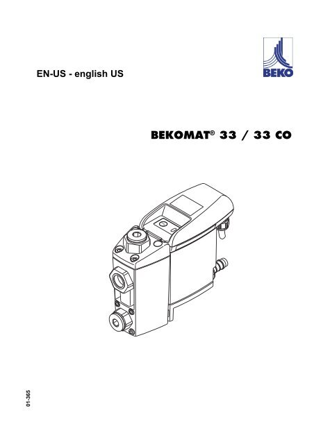
EN-<strong>US</strong> - <strong>english</strong> <strong>US</strong><br />
BEKOMAT ® <strong>33</strong> / <strong>33</strong> <strong>CO</strong>
Dear customer,<br />
Thank you for deciding in favor of the BEKOMAT ® <strong>33</strong> / <strong>33</strong> <strong>CO</strong> condensate drain. Please read the installation<br />
and operating instructions carefully before mounting and starting up the BEKOMAT ® <strong>33</strong> / <strong>33</strong> <strong>CO</strong>, and follow<br />
our directions. Perfect functioning of the BEKOMAT ® <strong>33</strong> / <strong>33</strong> <strong>CO</strong>, and thus reliable condensate discharge,<br />
can only be guaranteed when the provisions and notes stipulated here are strictly adhered to.<br />
Headquarter :<br />
Deutschland / Germany<br />
BEKO TECHNOLOGIES GMBH<br />
Im Taubental 7<br />
D-41468 Neuss<br />
Tel.: +49 (0)2131 988 0<br />
beko@beko.de<br />
India<br />
BEKO <strong>CO</strong>MPRESSED AIR<br />
TECHNOLOGIES Pvt. Ltd.<br />
Plot No.43/1, CIEEP, Gandhi Nagar,<br />
Balanagar, Hyderabad - 500 037, INDIA<br />
Tel +91 40 23080275<br />
eric.purushotham@bekoindia.com<br />
Benelux<br />
BEKO TECHNOLOGIES B.V.<br />
Vaartveld 25<br />
NL - 4704 SE Roosendaal<br />
Tel. +31 165 320 300<br />
info@beko.nl<br />
España / Spain<br />
BEKO Tecnológica España S.L.<br />
Polígono Industrial "Armenteres"<br />
C./Primer de Maig, no.6<br />
E-08980 Sant Feliu de Llobregat<br />
Tel. +34 93 632 76 68<br />
info.es@beko.de<br />
5eská Republica / Czech Republic<br />
BEKO TECHNOLOGIES s.r.o.<br />
Mlýnská 1392<br />
CZ - 562 01 Usti nad Orlici<br />
Tel. +420 465 52 12 51<br />
info.cz@beko.de<br />
������� / China<br />
BEKO TECHNOLOGIES (Shanghai) Co.<br />
Ltd.<br />
Rm.606 Tomson Commercial Building<br />
710 Dongfang Rd.<br />
Pudong Shanghai China<br />
P.C. 200122<br />
Tel. +86 21 508 158 85<br />
beko@beko.cn<br />
Italia / Italy<br />
BEKO TECHNOLOGIES S.r.l<br />
Via America 14<br />
I - 10071 Borgaro Torinese (TO)<br />
Tel. +39 0114 500 576<br />
info.it@beko.de<br />
Polska / Poland<br />
BEKO TECHNOLOGIES Sp. z o.o.<br />
ul. ChDapowskiego 47<br />
PL-02-787 Warszawa<br />
Tel +48 (0)22 855 30 95<br />
info.pl@beko.de<br />
South East Asia<br />
BEKO TECHNOLOGIES S.E.Asia (Thailand)<br />
Ltd.<br />
75/323 Romklao Road<br />
Sansab, Minburi<br />
Bangkok 10510<br />
Thailand<br />
Tel. +66 (0) 2-918-2477<br />
BEKO-info@beko-seasia.com<br />
United Kingdom<br />
BEKO TECHNOLOGIES LTD.<br />
2 West Court<br />
Buntsford Park Road<br />
Bromsgrove<br />
GB-Worcestershire B60 3DX<br />
Tel. +44 1527 575 778<br />
beko@beko-uk.com<br />
France<br />
BEKO TECHNOLOGIES S.a.r.l.<br />
Zone Industrielle<br />
1 Rue des Frères Remy<br />
F- 57200 Sarreguemines<br />
Tel. +<strong>33</strong> 387 283 800<br />
beko@wanadoo.fr<br />
�� / Japan<br />
BEKO TECHNOLOGIES K.K<br />
KEIHIN THINK 8 Floor<br />
1-1 Minamiwatarida-machi<br />
Kawasaki-ku, Kawasaki-shi<br />
JP-210-0855<br />
Tel. +81 44 328 76 01<br />
info@beko-technologies.co.jp<br />
Scandinavia<br />
BEKO TECHNOLOGIES AS<br />
P.O.Box 12 N-1393 Vollen<br />
Leangbukta 31<br />
N-1392 VETTRE<br />
Tel +47 31 29 10 50<br />
kjell@beko-technologies.no<br />
�� / Taiwan<br />
BEKO TECHNOLOGIES Co.,Ltd<br />
16F.-5, No.79, Sec. 1,<br />
Sintai 5th Rd., Sijhih City,<br />
Taipei County 221,<br />
Taiwan (R.O.C.)<br />
Tel. +886 2 8698 3998<br />
info@beko.com.tw<br />
<strong>US</strong>A<br />
BEKO TECHNOLOGIES <strong>CO</strong>RP.<br />
900 Great SW Parkway<br />
<strong>US</strong> - Atlanta, GA 30<strong>33</strong>6<br />
Tel. +1 (404) 924-6900<br />
beko@bekousa.com<br />
2 <strong>BEKOMAT®</strong> <strong>33</strong> / <strong>33</strong> <strong>CO</strong>
1 Safety instructions ..................................................................................................................................4<br />
2 Proper use..............................................................................................................................................5<br />
3 Exclusion from the scope of application.................................................................................................5<br />
4 Technical data ........................................................................................................................................6<br />
5 Dimension drawing.................................................................................................................................7<br />
6 Function..................................................................................................................................................8<br />
7 Installation ............................................................................................................................................10<br />
8 Electrical installation.............................................................................................................................13<br />
9 Control and maintenance .....................................................................................................................16<br />
10 Troubleshooting and fault elimination ..................................................................................................21<br />
11 Elements and components...................................................................................................................22<br />
12 Recommended spare parts..................................................................................................................23<br />
13 Accessories ..........................................................................................................................................23<br />
14 Declaration of conformity .....................................................................................................................24<br />
<strong>BEKOMAT®</strong> <strong>33</strong> / <strong>33</strong> <strong>CO</strong> 3
Safety instructions<br />
Pos : 1 / Beko Tec hnisc he Dokument ati on/Ü bersc hriften/1/Sic herheits hinweise @ 0\mod_1183637609261_15098.doc @ 15102<br />
1 Safety instructions<br />
Pos : 2 / Beko Tec hnisc he Dokument ati on/Gl obal e T exte/Allgemei ner Hi nweis BM @ 0\mod_1183615737313_15098.doc @ 15099<br />
Pos: 3 /Beko Technische Dokumentation/Sicherheit/Hinweis Anleitung BEKO <strong>US</strong>A @ 1\mod_1251202926517_15098.doc @ 15906<br />
Pos: 4 /Beko Technische Dokumentation/Sicherheit/Gefahr Druckluft @ 0\mod_1184148143854_15098.doc @ 15121<br />
Pos : 5 / Beko Tec hnisc he Dokument ati on/Sic herheit/M aß nahmen Dr uc kl uft BM @ 0\mod_1184148284291_15098.doc @ 15123<br />
Please check whether or not these instructions correspond to the device type.<br />
Adhere to all advice given in these operating instructions. They include essential information<br />
which must be observed during the installation, operation and maintenance. Therefore it is<br />
imperative for the service technician and the responsible operator / technical staff to read these<br />
operating instructions prior to installation, start-up and maintenance.<br />
The operating instructions must be accessible at any time at the place of application of the<br />
BEKOMAT ® <strong>33</strong> / <strong>33</strong> <strong>CO</strong>.<br />
In addition to these operating instructions, local or national regulations must be complied with,<br />
if necessary.<br />
Make sure that the BEKOMAT ® <strong>33</strong> / <strong>33</strong> <strong>CO</strong> is operated only within the permissible limit values<br />
indicated on the ID plate. Any deviation involves a risk for persons and materials, and may<br />
result in malfunction and service failures.<br />
If you have any queries regarding these installation- and operating instructions, please contact<br />
BEKO TECHNOLOGIES <strong>CO</strong>RP.<br />
Danger!<br />
Compressed air!<br />
Risk of serious injury or death through contact with quickly or suddenly escaping compressed<br />
air or through bursting plant components or plant components which are not<br />
secured.<br />
Measures:<br />
Do not exceed the maximum operating pressure (see type plate).<br />
Only carry out service measures when the system is pressure less.<br />
Use pressure-resistant installation material only.<br />
The feed pipe must be tubed firmly. Discharge pipe: short, fixed pressure hose onto pressure-resistant<br />
pipe.<br />
Make sure that persons or objects cannot be hit by condensate or escaping compressed air.<br />
Pos: 6 /Beko Technische Dokumentation/Sicherheit/Gefahr Netzspannung @ 0\mod_1184148186948_15098.doc @ 15122<br />
Pos: 7 /Beko Technische Dokumentation/Sicherheit/Maßnahmen Netzspannung BM 31/32/<strong>33</strong> @ 0\mod_1216898430699_15098.doc @ 15250<br />
Danger!<br />
Supply voltage!<br />
There is the risk of an electric shock involving injury or death when coming into contact<br />
with non-insulated components carrying supply voltage.<br />
Measures:<br />
During electric installations, all regulations in force need to be adhered to (e.g. VDE 0100).<br />
Service measures must only be undertaken when the system is deactivated.<br />
The removed control unit has no IP degree of protection.<br />
All types of electrical works must be carried out by authorized and qualified personnel only.<br />
Pos : 8 / Beko Tec hnisc he Dokument ati on/Sic herheit/Sicher heits hi nweis e, weitere BM (nic ht Ex) @ 0\mod_1183616103770_15098.doc @ 15100<br />
Further safety instructions:<br />
For installation and operation, the national regulations and safety codes in force must also be adhered<br />
to.<br />
Do not use the BEKOMAT <strong>33</strong> / <strong>33</strong> <strong>CO</strong> in hazardous areas.<br />
Regarding the inlet screw joints, excessive tightening forces must be avoided. This applies in particular<br />
to conical screw joints.<br />
The BEKOMAT <strong>33</strong> / <strong>33</strong> <strong>CO</strong> will only function when voltage is applied.<br />
Do not use the test button for permanent drainage.<br />
Use genuine spare parts only. This is imperative to ensure perfect functioning.<br />
Pos : 9 / Beko Tec hnisc he Dokument ati on/Sic herheit/Z us atz Sic her hei tshi nweise BM <strong>33</strong> @ 0\mod_1231926887620_15098.doc @ 15288<br />
4 <strong>BEKOMAT®</strong> <strong>33</strong> / <strong>33</strong> <strong>CO</strong>
Proper use<br />
Additional advice:<br />
During installation, use the spanner flat at the feed pipe (wrench size SW28 + 34) as a back rest.<br />
The service unit must not be dismantled.<br />
Pos : 10 /Beko T ec hnis che D okumentati on/Sic her hei t/Vorsic ht F ehlfunktion @ 0\mod_1214378096290_15098.doc @ 15237<br />
Pos: 11 /Beko Technische Dokumentation/Sicherheit/Maßnahmen Fehlfunktionen BM @ 0\mod_1214378434025_15098.doc @ 15238<br />
r<br />
Measures:<br />
Warning!<br />
Malfunction during operation!<br />
Through incorrect installation and poor maintenance, malfunction may occur at the<br />
BEKOMAT.<br />
Condensate which is not discharged may cause damage to plants and in production<br />
processes.<br />
Condensate drainage which is reliable in performance directly optimizes the compressed-air quality.<br />
To prevent damage and breakdowns, it is imperative to observe the following:<br />
Exact compliance with the specifications of use and with the performance parameters of the<br />
BEKOMAT, in connection with the case of application (see "Proper use" section)<br />
Exact compliance with the installation- and operation instructions in this manual<br />
Regular maintenance and control of the BEKOMAT in accordance with the instructions in this operating<br />
manual<br />
Pos: 12 /Beko Technische Dokumentation/Überschriften/1/Bestimmungsgemäße Verwendung @ 0\mod_1183637706293_15098.doc @ 15103<br />
2 Proper use<br />
Pos : 13 /Beko T ec hnis che D okumentati on/Besti mmungsgemäß e Ver wendung/BEKOM AT/Bes ti mmung. Ver wend. BM 31/32/<strong>33</strong> @ 0\mod_121<strong>33</strong>45398718_15098.doc @ 15218<br />
The BEKOMAT is an electronically level-controlled condensate drain for compressed-air plants.<br />
The device is employed within the permissible performance parameters (see "Technical data").<br />
The BEKOMAT is able to drain condensate under operating pressure from the plant components virtually<br />
without compressed-air loss.<br />
For its function, the BEKOMAT <strong>33</strong> / <strong>33</strong> <strong>CO</strong> requires an operating voltage and an operating pressure<br />
(see "Technical data").<br />
As far as the employment in plants with increased demands on compressed air is concerned (food industry,<br />
medical technology, laboratory equipment, special processes etc.), the operator must decide on<br />
measures for the monitoring of the compressed-air quality. These have an effect on the safety of the<br />
subsequent processes and may prevent damage to persons and plants.<br />
It is the task of the operator to ensure that the indicated conditions are met during the entire operating<br />
time.<br />
Pos : 14 /Beko T ec hnis che D okumentati on/Besti mmungsgemäß e Ver wendung/BEKOM AT/Hi nweis Anwendung BM <strong>33</strong> fürC O2-Anwendg. @ 0\mod_1242828875874_15098.doc @ 15317<br />
For the employment in <strong>CO</strong>2 plants, a BEKOMAT with a <strong>CO</strong> specification (e.g. BEKOMAT <strong>33</strong> <strong>CO</strong>) must<br />
be used.<br />
Pos : 15 /Beko T ec hnis che D okumentati on/Übersc hriften/1/Aussc hluss vom Anwendungs ber eich @ 0\mod_1236003439359_15098.doc @ 15308<br />
3 Exclusion from the scope of application<br />
Pos : 16 /Beko T ec hnis che D okumentati on/Besti mmungsgemäß e Ver wendung/BEKOM AT/Aus schl uß Anwendung BM 31/32/<strong>33</strong> @ 0\mod_1236003837511_15098.doc @ 15309<br />
The BEKOMAT as a condensate drain alone cannot guarantee a defined compressed-air quality, for<br />
this purpose, other additional technical devices are required.<br />
BEKOMAT <strong>33</strong> / <strong>33</strong> <strong>CO</strong> is not suitable for use in plants carrying vacuum or atmospheric ambient pressure<br />
or in ex-areas.<br />
The BEKOMAT must not be exposed to permanent direct solar or thermal radiation.<br />
The BEKOMAT <strong>33</strong> / <strong>33</strong> <strong>CO</strong> must not be installed and operated in areas with an aggressive atmosphere.<br />
Pos: 14 /---- Seitenumbruch ---- @ 0\mod_1157028099015_0.doc @ 2855<br />
Pos : 17 /Beko T ec hnis che D okumentati on/Besti mmungsgemäß e Ver wendung/BEKOM AT/Aus schl uß Anwendung BM nic ht für fros tgefähr dete Bereic he (Zusatz) @ 0\mod_1216106439206_15098.doc @ 15249<br />
Pos: 18 /---- Seitenumbruch ---- @ 0\mod_1157028099015_0.doc @ 15320<br />
The BEKOMAT <strong>33</strong> / <strong>33</strong> <strong>CO</strong> is not heatable and, therefore, not suitable for the use in areas where frost is<br />
likely to occur.<br />
<strong>BEKOMAT®</strong> <strong>33</strong> / <strong>33</strong> <strong>CO</strong> 5
Technical data<br />
Pos : 19 /Beko T ec hnis che D okument ati on/Übersc hriften/1/T ec hni sche D aten @ 0\mod_1184329570967_15098.doc @ 15131<br />
4 Technical data<br />
Pos : 20 /Beko T ec hnis che D okument ati on/Tec hnische D aten/BEKOM AT/T ec hn. D aten BM Standard ( ohne Leis tung, nicht Ex) @ 0\mod_1183725405008_15098.doc @ 15117<br />
min./max. operating pressure 0,8...16 bar (12...230 psi)<br />
min./max. temperature +1...+60 °C (+34...+140 °F)<br />
Condensate inflow 3 x NPT ½ (½") internal<br />
Condensate outflow G ½ (½") Ø 13 mm hose connector<br />
Condensate oil-contaminated + oil-free<br />
Housing aluminium + plastic, glass fibre-reinforced<br />
Weight (empty) 1,65 kg (3.63 lbs)<br />
Pos : 21 /Beko T ec hnis che D okument ati on/Tec hnische D aten/BEKOM AT/Leis tung BM Peak U SA @ 1\mod_1250085963108_15098.doc @ 15437<br />
Peak compressor performance 500 scfm<br />
Peak refrig. dryer performance<br />
(only with pre-separation)<br />
Peak filter performance<br />
(behind dryer)<br />
Pos: 22 /Beko Technische Dokumentation/Elektrische Daten/BEKOMAT/Elektrische Daten BM Standard @ 0\mod_1184051252992_15098.doc @ 15119<br />
Supply voltage<br />
(see type plate)<br />
1,000 scfm<br />
5,000 scfm<br />
Power consumption P < 3,0 VA (W)<br />
Recommended<br />
cable-jacket diameter<br />
Recommended<br />
wire cross-section<br />
Recommended<br />
stripping of cable jacket<br />
Recommended<br />
length of the wire end-tube<br />
Connection data of the<br />
potential-free contact<br />
Switch to load *)<br />
Connection data of the<br />
potential-free contact<br />
Switch to low signal *)<br />
230 / 115 /.../ 24 VAC ± 10 %, 50...60 Hz / 24 VDC ± 10 %<br />
Ø 5,8...8,5 mm (0.23"...0.34")<br />
3 x 0,75...1,5 mm² (0.03...0.06 inches squared)<br />
PE: approx. 60 mm (2.36") L/N: approx. 50 mm (1.97")<br />
~ 6 mm (~ 0.24 inch)<br />
AC: max. 250V / 1A<br />
DC: max 30V / 1A<br />
min. 5 VDC / 10mA<br />
Recommended fusing 0,5 A medium time lag<br />
Protection class IP 54<br />
VAC = V alternating current<br />
VDC = V direct current<br />
*) The switching of loads means that the properties of the contact are no longer suitable<br />
for the switching of low signals.<br />
Pos: 23 /---- Seitenumbruch ---- @ 0\mod_1157028099015_0.doc @ 15320<br />
6 <strong>BEKOMAT®</strong> <strong>33</strong> / <strong>33</strong> <strong>CO</strong>
Pos : 24 /Beko T ec hnis che D okumentati on/Übersc hriften/1/M aßz eichnung @ 0\mod_1183638072605_15098.doc @ 15109<br />
5 Dimension drawing<br />
Pos : 25 /Beko T ec hnis che D okumentati on/Tec hnische D aten/M assz eichnung @ 0\mod_1184569815280_15098.doc @ 15135<br />
Pos : 26 /Beko T ec hnis che D okumentati on/Tec hnische D aten/M assz eichnung Ergänzung SW @ 1\mod_1250153244115_15098.doc @ 15482<br />
SW = wrench size<br />
Pos: 27 /---- Seitenumbruch ---- @ 0\mod_1157028099015_0.doc @ 15320<br />
Dimension drawing<br />
<strong>BEKOMAT®</strong> <strong>33</strong> / <strong>33</strong> <strong>CO</strong> 7
Function<br />
Pos: 28 /Beko Technische Dokumentation/Überschriften/1/Funktion @ 0\mod_1183637775808_15098.doc @ 15104<br />
6 Function<br />
Pos: 29 /Beko Technische Dokumentation/Funktion/BEKOMAT/BM Ableitfunktion @ 0\mod_1183618031702_15098.doc @ 15101<br />
Pos: 30 /Beko Technische Dokumentation/Funktion/BEKOMAT/BM 32/<strong>33</strong> LED-Taster-Funktion @ 0\mod_1184163630011_15098.doc @ 15127<br />
Via the inlet line (1) the condensate flows into the<br />
BEKOMAT <strong>33</strong> / <strong>33</strong> <strong>CO</strong> and accumulates in the housing<br />
(2).<br />
A capacitive functioning sensor (3) continuously registers<br />
the filling level and relays a signal to the electronic<br />
control as soon as the container is filled.<br />
The pilot valve (4) is activated and the membrane (5)<br />
opens the outlet line to discharge the condensate (6).<br />
When the BEKOMAT is empty, the outlet line is reclosed<br />
tightly in time before unnecessary compressedair<br />
losses occur.<br />
Two LEDs show the individual operating states of the<br />
BEKOMAT <strong>33</strong> / <strong>33</strong> <strong>CO</strong> .<br />
Ready to operate, voltage is applied.<br />
In the event that the condensate discharge is disturbed,<br />
an alarm mode starts which is indicated by<br />
flashing of the red alarm LED.<br />
Malfunction /alarm<br />
Test of the valve function (manual drainage): Press<br />
the button for approx. two seconds.<br />
Test of the alarm function (see below): Press the button<br />
for at least one minute.<br />
Do not use for permanent drainage.<br />
8 <strong>BEKOMAT®</strong> <strong>33</strong> / <strong>33</strong> <strong>CO</strong>
Pos : 31 /Beko T ec hnis che D okumentati on/Funkti on/BEKOMAT/BM- Alar mmodus ( nicht Vario) @ 0\mod_1185868789656_15098.doc @ 15163<br />
.<br />
Switching sequence of the valve in the alarm<br />
mode<br />
Trouble indication via a potential-free contact<br />
Pos: 32 /---- Seitenumbruch ---- @ 0\mod_1157028099015_0.doc @ 15320<br />
Function<br />
Alarm mode:<br />
In the event that the condensate discharge is disturbed,<br />
the valve opens after a time cycle (approx.<br />
every three seconds) to eliminate the malfunction<br />
automatically. If the malfunction is not eliminated after<br />
one minute, a trouble indication is released:<br />
The alarm LED flashes<br />
The alarm relay switches over (the signal can be<br />
picked off potential-freely).<br />
The valve opens every four minutes for 7.5 seconds.<br />
When the malfunction has been eliminated, the<br />
BEKOMAT will switch back automatically into the<br />
normal mode.<br />
Possible trouble sources include:<br />
Mistakes during installation<br />
Dropping below the minimum pressure<br />
Excessive accumulation of condensate (excess<br />
load)<br />
Blocked / obstructed outlet line<br />
Extreme amount of dirt particles<br />
Frozen pipe work<br />
<strong>BEKOMAT®</strong> <strong>33</strong> / <strong>33</strong> <strong>CO</strong> 9
Installation<br />
Pos : <strong>33</strong> /Beko T ec hnis che D okument ati on/Übersc hriften/1/Ins tall ati on @ 0\mod_1183637835418_15098.doc @ 15105<br />
7 Installation<br />
Pos : 34 /Beko T ec hnis che D okument ati on/Sic her hei t/Gefahr Druc kl uft @ 0\mod_1184148143854_15098.doc @ 15121<br />
Pos: 35 /Beko Technische Dokumentation/Sicherheit/Maßnahmen Druckluft BM @ 0\mod_1184148284291_15098.doc @ 15123<br />
Measures:<br />
Danger!<br />
Compressed air!<br />
Risk of serious injury or death through contact with quickly or suddenly escaping compressed<br />
air or through bursting plant components or plant components which are not<br />
secured.<br />
Do not exceed the maximum operating pressure (see type plate).<br />
Only carry out service measures when the system is pressure less.<br />
Use pressure-resistant installation material only.<br />
The feed pipe must be tubed firmly. Discharge pipe: short, fixed pressure hose onto pressure-resistant<br />
pipe.<br />
Make sure that persons or objects cannot be hit by condensate or escaping compressed air.<br />
Pos : 36 /Beko T ec hnis che D okument ati on/Sic her hei t/Vorsic ht F ehlfunktion @ 0\mod_1214378096290_15098.doc @ 15237<br />
Pos: 37 /Beko Technische Dokumentation/Sicherheit/Maßnahmen Fehlfunktionen BM @ 0\mod_1214378434025_15098.doc @ 15238<br />
r<br />
Measures:<br />
Warning!<br />
Malfunction during operation!<br />
Through incorrect installation and poor maintenance, malfunction may occur at the<br />
BEKOMAT.<br />
Condensate which is not discharged may cause damage to plants and in production<br />
processes.<br />
Condensate drainage which is reliable in performance directly optimizes the compressed-air quality.<br />
To prevent damage and breakdowns, it is imperative to observe the following:<br />
Exact compliance with the specifications of use and with the performance parameters of the<br />
BEKOMAT, in connection with the case of application (see "Proper use" section)<br />
Exact compliance with the installation- and operation instructions in this manual<br />
Regular maintenance and control of the BEKOMAT in accordance with the instructions in this operating<br />
manual<br />
Pos : 38 /Beko T ec hnis che D okument ati on/Sic her hei t/Hinweis Ins tall ati on und Wartung @ 0\mod_12<strong>33</strong>239666823_15098.doc @ 15301<br />
Note<br />
It is imperative to observe all hazard statements and warnings listed here.<br />
Please also observe all regulations and notes regarding industrial safety and fire prevention at the place of<br />
installation.<br />
As a matter of principle, only use suitable and appropriate tools and materials in a proper condition.<br />
Do not use aggressive cleaners.<br />
Please note that condensates may contain aggressive or harmful components. Therefore, skin contact<br />
should be avoided.<br />
Condensate is subject to mandatory waste disposal. As such, it must be collected in suitable containers, and<br />
disposed of or processed properly.<br />
Pos : 39 /Beko T ec hnis che D okument ati on/Inst allati on/BEKOMAT /BM 31/32/<strong>33</strong> ( nicht Vario) Installati onshi nweis e @ 0\mod_1184161640511_15098.doc @ 15126<br />
10 <strong>BEKOMAT®</strong> <strong>33</strong> / <strong>33</strong> <strong>CO</strong>
Installation instructions:<br />
Installation<br />
Only the displayed installation position of the<br />
BEKOMAT (3) is permissible. Never install in a<br />
horizontal or any other tilted position.<br />
Feed pipe (1) and ball valve (2) at least G½.<br />
No filter or screen in the inlet line.<br />
Slope in the inlet line >1%.<br />
Use ball valves (2) only.<br />
Operating pressure: min. 12 psi, max. 230 psi.<br />
Short pressure hose (4) fixed on a pressureresistant<br />
pipe.<br />
The required minimum pressure increases by<br />
0.44 psi per foot gradient in the discharge pipe (5).<br />
Discharge pipe (5) rising by max. 16.4 feet.<br />
Install manifold (7) ¾" with a slope of at least 1%.<br />
Introduce the discharge pipe (6) from the top into<br />
the manifold (7).<br />
Prior to the start-up, always carry out a leak test<br />
and verify the correct engagement of the control<br />
unit.<br />
<strong>BEKOMAT®</strong> <strong>33</strong> / <strong>33</strong> <strong>CO</strong> 11
Installation<br />
Pos: 40 /---- Seitenumbruch ---- @ 0\mod_1157028099015_0.doc @ 15320<br />
wrong correct<br />
Pressure differences!<br />
Each condensate accumulation point must be drained<br />
separately.<br />
Continuous slope!<br />
Avoid a water pocket when installing the feed pipe<br />
Deflector area!<br />
If drainage is to be carried out directly from the pipe,<br />
deflection of the air flow will be useful.<br />
Ventilation!<br />
If the slope in the inlet line is not sufficient or if any<br />
other inflow problems occur, a venting line needs to be<br />
installed.<br />
12 <strong>BEKOMAT®</strong> <strong>33</strong> / <strong>33</strong> <strong>CO</strong>
Pos : 41 /Beko T ec hnis che D okumentati on/Übersc hriften/1/Elektrische Install ati on @ 0\mod_1183638507355_15098.doc @ 15116<br />
8 Electrical installation<br />
Pos : 42 /Beko T ec hnis che D okumentati on/Sic her hei t/Gefahr Netzs pannung @ 0\mod_1184148186948_15098.doc @ 15122<br />
Pos : 43 /Beko T ec hnis che D okumentati on/Sic her hei t/Maßnahmen N etzs pannung BM 31/32/<strong>33</strong> @ 0\mod_1216898430699_15098.doc @ 15250<br />
Electrical installation<br />
Danger!<br />
Supply voltage!<br />
There is the risk of an electric shock involving injury or death when coming into contact<br />
with non-insulated components carrying supply voltage.<br />
Measures:<br />
During electric installations, all regulations in force need to be adhered to (e.g. VDE 0100).<br />
Service measures must only be undertaken when the system is deactivated.<br />
The removed control unit has no IP degree of protection.<br />
All types of electrical works must be carried out by authorized and qualified personnel only.<br />
Pos : 44 /Beko T ec hnis che D okumentati on/Installati on/BEKOMAT /El ektrInstallation Hi nweis e BM32/<strong>33</strong> allg. @ 0\mod_1229594032288_15098.doc @ 15285<br />
Pos : 45 /Beko T ec hnis che D okument ati on/Inst allati on/BEKOMAT /Kl emmenbel egung BM 32/ <strong>33</strong> @ 0\ mod_1184228120061_15098.doc @ 15128<br />
Note:<br />
Power supply connection:<br />
1. Read the permissible supply voltage on the ID plate<br />
and make sure this voltage is observed.<br />
2. Carry out installation in accordance with VDE 0100.<br />
3. Observe the terminal assignment.<br />
4. Do not install when the device is energised.<br />
5. Unscrew the screw (1) and remove the upper part<br />
of the cover (2).<br />
6. Unscrew the threaded cable connection (3)<br />
(in case there is any), remove the plug and lead<br />
the cable (4) for the supply voltage through.<br />
7. Connect the cable (4) with the terminals KL1 (1.1 ...<br />
1.3) (5).<br />
8. Install the cables as shown (see also pin assignment).<br />
9. Tighten the threaded cable connection (3) with a<br />
slight sealing effect.<br />
10.Put on the upper part of the cover (2) and tighten<br />
the screw (1) fingertight.<br />
Connection of the potential-free contact and of<br />
the external test:<br />
1. Selection of the suitable cable.<br />
2. Connection to KL2 and KL3, as is shown on the following<br />
page.<br />
3. The installation steps are the same as for the power<br />
supply connection.<br />
<strong>BEKOMAT®</strong> <strong>33</strong> / <strong>33</strong> <strong>CO</strong> 13
Electrical installation<br />
Terminal assignment AC version (operating voltage)<br />
KL 1 KL 2 KL 3<br />
1 2 3 2 3 4 1 2<br />
phase/neutral<br />
1.1<br />
neutral/phase<br />
1.2<br />
earth/ground<br />
1.3<br />
normally closed<br />
2.2<br />
common<br />
2.3<br />
normally open<br />
2.4<br />
0 V<br />
3.1<br />
external test<br />
3.2<br />
Terminal assignment DC version (operating voltage)<br />
KL 1 KL 2 KL 3<br />
1 2 3 2 3 4 1 2<br />
+24 V<br />
1.1<br />
neutral 0 V<br />
1.2<br />
earth/ground<br />
1.3<br />
normally closed<br />
2.2<br />
common<br />
2.3<br />
normally open<br />
2.4<br />
0 V<br />
3.1<br />
external test<br />
3.2<br />
KL 1.1 L or N mains connection<br />
KL 1.2 N or L mains connection<br />
KL 1.3 PE mains connection<br />
L = Outer conductor (black)<br />
N = Neutral conductor (blue)<br />
PE = Protective earth conductor (green-yellow)<br />
KL 1.1 + 24 V<br />
KL 1.2 0 V<br />
KL 1.3 PE mains connection<br />
Terminal assignment of the potential-free contact and of the external test (AC and DC versions)<br />
KL 1 KL 2 KL 3<br />
1 2 3 2 3 4 1 2<br />
+24 V<br />
1.1<br />
neutral 0 V<br />
1.2<br />
earth/ground<br />
1.3<br />
normally closed<br />
2.2<br />
common<br />
2.3<br />
normally open<br />
2.4<br />
0 V<br />
3.1<br />
external test<br />
3.2<br />
Alarm / potential-free contact:<br />
KL 2.2 n.c.<br />
KL 2.3 com.<br />
KL 2.4 n.o.<br />
n.c. - com. closed during malfunction or voltage breakdown<br />
(standby-current principle)<br />
n.o. - com. closed during normal operation<br />
Contacts KL 2.2 - 2.4 are potential-free.<br />
External test / remote control:<br />
KL 3.1 0V<br />
KL 3.2 external test (IN1)<br />
Contacts connected = test active = discharge<br />
Contacts open = test inactive<br />
Contacts KL 3.1 -3.2 are not potential-free.<br />
14 <strong>BEKOMAT®</strong> <strong>33</strong> / <strong>33</strong> <strong>CO</strong>
Note:<br />
Electrical installation<br />
Between terminals KL 1.1 - 1.3 of the VDC units and housings or the condensate connections, there is no<br />
galvanic isolation.<br />
The provided 24 VDC voltage must comply with the requirements for safety extra-low voltages (e.g. EN<br />
61556-2-6).<br />
Tighten the threaded cable connection with a slight sealing effect.<br />
Pos: 46 /Beko Technische Dokumentation/Installation/BEKOMAT/E-Schema @ 0\mod_12<strong>33</strong>758178163_15098.doc @ 15305<br />
Electric diagram<br />
Pos: 47 /---- Seitenumbruch ---- @ 0\mod_1157028099015_0.doc @ 15320<br />
<strong>BEKOMAT®</strong> <strong>33</strong> / <strong>33</strong> <strong>CO</strong> 15
Control and maintenance<br />
Pos : 48 /Beko T ec hnis che D okument ati on/Übersc hriften/1/Kontr olle und Wartung @ 0\mod_1183637885371_15098.doc @ 15106<br />
9 Control and maintenance<br />
Pos : 49 /Beko T ec hnis che D okument ati on/Sic her hei t/Gefahr Druc kl uft @ 0\mod_1184148143854_15098.doc @ 15121<br />
Pos: 50 /Beko Technische Dokumentation/Sicherheit/Maßnahmen Druckluft BM @ 0\mod_1184148284291_15098.doc @ 15123<br />
Measures:<br />
Danger!<br />
Compressed air!<br />
Risk of serious injury or death through contact with quickly or suddenly escaping compressed<br />
air or through bursting plant components or plant components which are not<br />
secured.<br />
Do not exceed the maximum operating pressure (see type plate).<br />
Only carry out service measures when the system is pressure less.<br />
Use pressure-resistant installation material only.<br />
The feed pipe must be tubed firmly. Discharge pipe: short, fixed pressure hose onto pressure-resistant<br />
pipe.<br />
Make sure that persons or objects cannot be hit by condensate or escaping compressed air.<br />
Pos : 51 /Beko T ec hnis che D okument ati on/Sic her hei t/Gefahr Netzs pannung @ 0\mod_1184148186948_15098.doc @ 15122<br />
Pos : 52 /Beko T ec hnis che D okument ati on/Sic her hei t/Maßnahmen N etzs pannung BM 31/32/<strong>33</strong> @ 0\mod_1216898430699_15098.doc @ 15250<br />
Danger!<br />
Supply voltage!<br />
There is the risk of an electric shock involving injury or death when coming into contact<br />
with non-insulated components carrying supply voltage.<br />
Measures:<br />
During electric installations, all regulations in force need to be adhered to (e.g. VDE 0100).<br />
Service measures must only be undertaken when the system is deactivated.<br />
The removed control unit has no IP degree of protection.<br />
All types of electrical works must be carried out by authorized and qualified personnel only.<br />
Pos : 53 /Beko T ec hnis che D okument ati on/Sic her hei t/Vorsic ht F ehlfunktion @ 0\mod_1214378096290_15098.doc @ 15237<br />
Pos: 54 /Beko Technische Dokumentation/Sicherheit/Maßnahmen Fehlfunktionen BM @ 0\mod_1214378434025_15098.doc @ 15238<br />
r<br />
Measures:<br />
Warning!<br />
Malfunction during operation!<br />
Through incorrect installation and poor maintenance, malfunction may occur at the<br />
BEKOMAT.<br />
Condensate which is not discharged may cause damage to plants and in production<br />
processes.<br />
Condensate drainage which is reliable in performance directly optimizes the compressed-air quality.<br />
To prevent damage and breakdowns, it is imperative to observe the following:<br />
Exact compliance with the specifications of use and with the performance parameters of the<br />
BEKOMAT, in connection with the case of application (see "Proper use" section)<br />
Exact compliance with the installation- and operation instructions in this manual<br />
Regular maintenance and control of the BEKOMAT in accordance with the instructions in this operating<br />
manual<br />
Pos : 55 /Beko T ec hnis che D okument ati on/Sic her hei t/Hinweis Ins tall ati on und Wartung @ 0\mod_12<strong>33</strong>239666823_15098.doc @ 15301<br />
Note<br />
It is imperative to observe all hazard statements and warnings listed here.<br />
Please also observe all regulations and notes regarding industrial safety and fire prevention at the place of<br />
installation.<br />
As a matter of principle, only use suitable and appropriate tools and materials in a proper condition.<br />
Do not use aggressive cleaners.<br />
Please note that condensates may contain aggressive or harmful components. Therefore, skin contact<br />
16 <strong>BEKOMAT®</strong> <strong>33</strong> / <strong>33</strong> <strong>CO</strong>
Control and maintenance<br />
should be avoided.<br />
Condensate is subject to mandatory waste disposal. As such, it must be collected in suitable containers, and<br />
disposed of or processed properly.<br />
Pos : 56 /Beko T ec hnis che D okumentati on/Wartung/BEKOM AT/Wartung BM <strong>33</strong> (nic ht Vari o) <strong>US</strong>A 6400h @ 1\mod_1251204635751_15098.doc @ 15937<br />
Maintenance recommendation:<br />
Replace the service unit (9) after 6 400 operating<br />
hours or max. two years.<br />
It is recommended to clean the condensate receiver<br />
tank after two years at the latest, when maintenance<br />
works are carried out:<br />
1. Remove the control unit (1...8) by pressing the<br />
arresting hook (23)<br />
2. Unfasten BEKOMAT from the outlet<br />
3. Detach BEKOMAT from the tubing at the inlet<br />
4. Unscrew both M6 bolts (22) and remove the<br />
service unit (9) by slightly pulling and lifting it<br />
5. Remove the design shell (11) using a screwdriver<br />
6. Unscrew the four cover screws (16) and remove<br />
the cover (17)<br />
7. Clean the condensate receiver tank (19)<br />
<strong>BEKOMAT®</strong> <strong>33</strong> / <strong>33</strong> <strong>CO</strong> 17
Control and maintenance<br />
8. Insert new cover O-ring (18) according to the<br />
diagram<br />
9. Clean the sealing surfaces of the cover<br />
10. Put on the cover (17) with the new O-ring and<br />
carefully tighten the four cover screws (16)<br />
crosswise (8 Nm)<br />
11. Clean the sealing surfaces ( ) at the condensate<br />
receiver tank (19)<br />
18 <strong>BEKOMAT®</strong> <strong>33</strong> / <strong>33</strong> <strong>CO</strong>
Control and maintenance<br />
12. Check whether or not the service unit (9) goes<br />
with the control unit (1...8) (model designation<br />
and color of the arresting hook)<br />
13. Check the O-rings at the new service unit (12,<br />
13)<br />
14. Mount the design shell (11)<br />
15. Mount the service unit along with the design<br />
shell at the condensate receiver tank (19) and<br />
tighten both erection bolts (22) (2,5 Nm)<br />
16. Re-install the BEKOMAT at the inlet tubing and<br />
outlet, in reverse order to disassembly<br />
<strong>BEKOMAT®</strong> <strong>33</strong> / <strong>33</strong> <strong>CO</strong> 19
Control and maintenance<br />
Pos: 57 /---- Seitenumbruch ---- @ 0\mod_1157028099015_0.doc @ 15320<br />
Installation of the control unit on the service unit<br />
BEKOMAT:<br />
1. Check whether or not the service unit with contact<br />
springs (28) is clean, dry and free from impurities.<br />
2. Introduce the sensor (5) into the service unit (9).<br />
3. Insert the hook (29) of the control unit (1...8) in<br />
the service unit (9).<br />
4. Press the control unit (1...8) against the service<br />
unit (9), snap into place and make sure it is securely<br />
mounted.<br />
Start-up subsequent to maintenance measures:<br />
Always carry out prior to the start-up:<br />
Leak test of the screwed connector of the condensate<br />
receiver tank and of the connection of<br />
this tank to the service unit<br />
Control of the electrical connections<br />
Check of the correct engagement of the control<br />
unit<br />
20 <strong>BEKOMAT®</strong> <strong>33</strong> / <strong>33</strong> <strong>CO</strong>
Pos : 58 /Beko T ec hnis che D okumentati on/Übersc hriften/1/F ehlers uc he und Fehl erbehebung @ 0\mod_1183637945027_15098.doc @ 15107<br />
10 Troubleshooting and fault elimination<br />
Pos : 59 /Beko T ec hnis che D okumentati on/Fehlers uc he/BEKOMAT /Fehl ersuc he BM <strong>33</strong>/<strong>33</strong>V @ 0\mod_1232465952726_15098.doc @ 15295<br />
Troubleshooting and fault elimination<br />
Symptoms Possible reasons Measures<br />
LED does not light up<br />
Test button pressed,<br />
but no condensate<br />
discharge<br />
Condensate discharge<br />
only when the test button<br />
is pressed<br />
Device blows off continuously<br />
The device is not tight<br />
Pos: 60 /---- Seitenumbruch ---- @ 0\mod_1157028099015_0.doc @ 15320<br />
Supply voltage incorrect<br />
Circuit board defective<br />
Feed pipe and / or discharge pipe<br />
blocked or obstructed<br />
Wear and tear<br />
Circuit board defective<br />
Service unit defective<br />
Minimum pressure not reached<br />
Maximum pressure exceeded<br />
Feed pipe without sufficient slope<br />
Cross section not large enough<br />
Condensate accumulation too high<br />
(surge)<br />
Service unit extremely dirty<br />
Check voltage on the type plate<br />
Check the connections and the supply<br />
voltage<br />
Check the circuit boards for possible<br />
damage<br />
Check feed and discharge pipe<br />
Check whether or not the valve opens<br />
audibly (press the test button several<br />
times for >2 seconds)<br />
Check the circuit board for possible<br />
damage<br />
Check the operating pressure<br />
Install feed pipe with a slope<br />
Replace the service unit<br />
Service unit defective or dirty Replace the service unit<br />
O-rings between the condensate<br />
receiver tank and the service unit<br />
are defective or the sealing surfaces<br />
are dirty<br />
The screw joints are not tightened<br />
Check the screw joints<br />
Dismantle the service unit, control the<br />
O-rings and sealing surfaces<br />
Replace O-rings if required and clean<br />
the sealing surfaces<br />
Check tightness after the installation<br />
<strong>BEKOMAT®</strong> <strong>33</strong> / <strong>33</strong> <strong>CO</strong> 21
Elements and components<br />
Pos : 61 /Beko T ec hnis che D okument ati on/Übersc hriften/1/Bauteile und Komponenten @ 0\mod_1183638014355_15098.doc @ 15108<br />
11 Elements and components<br />
Pos : 62 /Beko T ec hnis che D okument ati on/Bauteil e und Komponenten/BEKOMAT/Bauteil e BM <strong>33</strong> ( nicht Vario) @ 0\mod_1231929865<strong>33</strong>9_15098.doc @ 15289<br />
1 Screw 3.5 x 10<br />
2 Upper part of the cover<br />
3 Molded gasket<br />
4 Circuit board<br />
5 Sensor<br />
6 Lower part of the cover<br />
7 Cable bushing<br />
8 Cord packing 2.5 x 235<br />
9 Service unit<br />
10 Hose connector G ½<br />
11 Design shell<br />
Pos: 63 /---- Seitenumbruch ---- @ 0\mod_1157028099015_0.doc @ 15320<br />
12 O-ring 8 x 4<br />
13 O-ring 18.5 x 2<br />
14 Locking screw G ½<br />
15 Flat gasket<br />
16 Hexagon socket head screw M6 x 16<br />
17 Lid<br />
18 O-ring 48.9 x 2.62<br />
19 Condensate receiver tank<br />
20 Flat gasket<br />
21 Locking screw G ½<br />
22 Cross recessed head screw M6 x 16<br />
22 <strong>BEKOMAT®</strong> <strong>33</strong> / <strong>33</strong> <strong>CO</strong>
Pos : 64 /Beko T ec hnis che D okumentati on/Übersc hriften/1/Empfohl ene Ersatzteile @ 0\mod_1183638186183_15098.doc @ 15111<br />
12 Recommended spare parts<br />
Pos: 65 /Beko Technische Dokumentation/Ersatzteile Zubehör/BEKOMAT/Ersatzteile BEKOMAT <strong>33</strong> @ 0\mod_1232540565156_15098.doc @ 15296<br />
Available sets of spare parts Contents Order number<br />
Recommended spare parts<br />
Service unit 9, 12, 13 XE KA<strong>33</strong> 101 SAP no. 4012873<br />
Service unit <strong>CO</strong> 9, 12, 13 XE KA<strong>33</strong> 103 SAP no. 4012872<br />
Gasket kit 3, 8, 12, 13, 18 XE KA<strong>33</strong> 002 SAP no. 4012922<br />
Design shell 11 XE KA32 011 SAP no. 4010167<br />
Pos : 66 /Beko T ec hnis che D okumentati on/Übersc hriften/1/Z ubehör @ 0\mod_1232362905455_15098.doc @ 15293<br />
13 Accessories<br />
Pos : 67 /Beko T ec hnis che D okumentati on/Ers atzteile Zubehör/BEKOM AT/H altewinkel BM <strong>33</strong> @ 0\mod_12<strong>33</strong>244627657_15098.doc @ 15302<br />
Available accessory sets Contents Order number<br />
Mounting brackets<br />
for wall and base<br />
Pos : 68 /Beko T ec hnis che D okument ati on/Ers atzt eile Zubehör/BEKOM AT/ Anschl uss-Abl auf-Set BEKOM AT 13/<strong>33</strong> ( nicht Vari o) @ 0\mod_1232621370007_15098.doc @ 15298<br />
24 (Mounting bracket)<br />
25 (Washer)<br />
26 (Hexagon socket head<br />
screw)<br />
Available accessory sets Contents Order number<br />
Connection set<br />
With manual drainage, valve for<br />
inlet with screw joint<br />
Connection set<br />
With manual drainage, valves for<br />
venting line and inlet with<br />
screw joint<br />
Outlet set<br />
With hose and<br />
installation material<br />
Pos: 69 /---- Seitenumbruch ---- @ 0\mod_1157028099015_0.doc @ 15320<br />
Ball valve G½ PN25<br />
Ball valve G¼PN10<br />
Reducing adapter G½ - G¼ Ms<br />
Double nipple G¼ Ms<br />
Ball valve G½ PN25<br />
Ball valve G¼ PN10<br />
Reducing adapter G½ - G¼ Ms<br />
Double nipple G¼ Ms<br />
T-piece G½ Ms nickel-plated<br />
Lock nut Rp½ Ms<br />
Tubing piece 13.3x3.3x800<br />
Grommet 13-G½ Ms SW24<br />
Hose clamp 16-27/12<br />
XZ KA<strong>33</strong> 001 SAP no. 4012883<br />
XZ KA13 003<br />
SAP no. 2000040<br />
XZ KA13 004<br />
SAP no. 2000041<br />
XZ KA12 001<br />
SAP no. 2000046<br />
<strong>BEKOMAT®</strong> <strong>33</strong> / <strong>33</strong> <strong>CO</strong> 23
Declaration of conformity<br />
Pos : 70 /Beko T ec hnis che D okument ati on/Übersc hriften/1/Konfor mitäts er klär ung @ 0\mod_1210752269256_15098.doc @ 15184<br />
14 Declaration of conformity<br />
Pos : 71 /Beko T ec hnis che D okument ati on/Zertifi kate/Er klär ung en/BEKOMAT 31-<strong>33</strong>-EG-Konfor mScan @ 0\mod_11845782562<strong>33</strong>_15098.doc @ 15138<br />
Pos: 72 /---- Seitenumbruch ---- @ 0\mod_1157028099015_0.doc @ 15320<br />
24 <strong>BEKOMAT®</strong> <strong>33</strong> / <strong>33</strong> <strong>CO</strong>
Pos : 73 /Beko T ec hnis che D okumentati on/Zertifi kate/Er klär ung en/BEKOMAT 31-<strong>33</strong>-EG-Konfor mWord @ 0\mod_1232550307641_15098.doc @ 15297<br />
BEKO TECHNOLOGIES GMBH<br />
41468 Neuss, GERMANY<br />
Tel: +49 2131 988-0<br />
www.beko.de<br />
EC Declaration of Conformity<br />
Declaration of conformity<br />
We hereby declare that the products indicated hereafter, in the delivered performance, comply with the stipulations<br />
of the relevant standards:<br />
Product designation: Condensate drain<br />
Types: BEKOMAT 31, 32, <strong>33</strong><br />
Voltage options: 24VAC, 24VDC, 100VAC, 115VAC, 200VAC, 230VAC<br />
Pressure options: 0.8 - 16 bar operating pressure<br />
Product description and function: Condensate drain for the electronically level-controlled<br />
discharge of condensate in the compressed-air system.<br />
Low-Voltage Directive 2006/95/EC<br />
Harmonized standards applied: EN 60730-1:2000 + A1:2004 + A12:2003 + A13:2004 +<br />
A14:2005 + A15:2007<br />
EN 60730-2-15:1995 + A1:1998 + A11:2005<br />
Year of CE labeling: BEKOMAT 31, 32: 06<br />
BEKOMAT <strong>33</strong>: 09<br />
EMC Directive 2004/108/EC<br />
Applied standards: EN 61000-3-2:2006<br />
EN 61000-3-3:1995: + A1:2001 + A2:2005<br />
EN 61000-6-3:2007<br />
EN 61000-6-2:2005<br />
The devices are labeled with the sign shown below:<br />
This declaration only refers to products in the condition in which they have been placed into circulation. Parts<br />
which have not been installed by the manufacturer and / or modifications which have been implemented<br />
subsequently remain unconsidered.<br />
Neuss, 7 April 2009 BEKO TECHNOLOGIES GMBH<br />
Pos: 74 /Beko Technische Dokumentation/Globale Texte/Vorbehaltsklausel @ 0\mod_12137040<strong>33</strong>153_15098.doc @ 15236<br />
===== Ende der Stückliste =====<br />
p.p. Christian Riedel<br />
Quality manager<br />
<strong>BEKOMAT®</strong> <strong>33</strong> / <strong>33</strong> <strong>CO</strong> 25
A<br />
Accessories.........................................................23<br />
Accessory sets....................................................23<br />
Alarm mode...........................................................9<br />
Angle adapter......................................................22<br />
B<br />
Blows off .............................................................21<br />
C<br />
Circuit board........................................................22<br />
Clean condensate receiver tank .........................17<br />
Components........................................................22<br />
Condensate discharge disturbed........................21<br />
Control ................................................................16<br />
D<br />
Danger compressed air ........................... 4, 10, 16<br />
Danger supply voltage ............................. 4, 13, 16<br />
Data ......................................................................6<br />
Declaration of conformity ....................................24<br />
Deflector area .....................................................12<br />
Degree of protection ................................ 4, 13, 16<br />
Dimension drawing ...............................................7<br />
Dimensions ...........................................................7<br />
E<br />
Electric diagram ..................................................15<br />
Electrical data .......................................................6<br />
Electrical installation ...........................................13<br />
Elements .............................................................22<br />
Exclusion from the scope of application ...............5<br />
Exclusion of a field of application..........................5<br />
F<br />
Failure .................................................................21<br />
Fault clearance ...................................................21<br />
Fault diagnosis....................................................21<br />
Fault elimination..................................................21<br />
Feed pipe ............................................................12<br />
Field of application................................................5<br />
Filling level ............................................................8<br />
Function ................................................................8<br />
I<br />
Inlet line.................................................................8<br />
Installation...........................................................10<br />
Instructions, safety instructions.............................4<br />
Intermediate adapter...........................................22<br />
L<br />
LED does not light up......................................... 21<br />
Lower part of the cover ...................................... 22<br />
M<br />
Maintenance....................................................... 16<br />
Maintenance recommendation........................... 17<br />
Malfunction......................................................... 21<br />
Membrane ............................................................ 8<br />
Mounting ............................................................ 10<br />
N<br />
No condensate discharge .................................. 21<br />
O<br />
Order number..................................................... 23<br />
Outlet line ............................................................. 8<br />
P<br />
Pilot valve............................................................. 8<br />
Pressure differences .......................................... 12<br />
Proper use............................................................ 5<br />
Q<br />
Qualified personnel .................................. 4, 13, 16<br />
R<br />
Recommended spare parts................................ 23<br />
S<br />
Safety extra-low voltages................................... 15<br />
Safety instructions................................................ 4<br />
Sensor................................................................ 22<br />
Service measures .................................... 4, 10, 16<br />
Service unit .................................................. 17, 22<br />
Sets of spare parts............................................. 23<br />
Slope .................................................................. 12<br />
Spare parts..................................................... 4, 23<br />
T<br />
Technical data...................................................... 6<br />
Trouble sources ................................................... 9<br />
Troubleshooting ................................................. 21<br />
U<br />
Upper part of the cover ...................................... 22<br />
V<br />
Venting line ........................................................ 12<br />
W<br />
Water pocket...................................................... 12<br />
26 <strong>BEKOMAT®</strong> <strong>33</strong> / <strong>33</strong> <strong>CO</strong>
<strong>BEKOMAT®</strong> <strong>33</strong> / <strong>33</strong> <strong>CO</strong> 27
Printed in Germany<br />
Subject to technical modifications without notice / errors accepted.<br />
BM<strong>33</strong>_manual_en_usa_2009_08<br />
<strong>BEKOMAT®</strong> <strong>33</strong> / <strong>33</strong> <strong>CO</strong>