Replacement Parts for Model F, FE, B, and BE Gas-Fired ... - Reznor
Replacement Parts for Model F, FE, B, and BE Gas-Fired ... - Reznor
Replacement Parts for Model F, FE, B, and BE Gas-Fired ... - Reznor

Create successful ePaper yourself
Turn your PDF publications into a flip-book with our unique Google optimized e-Paper software.
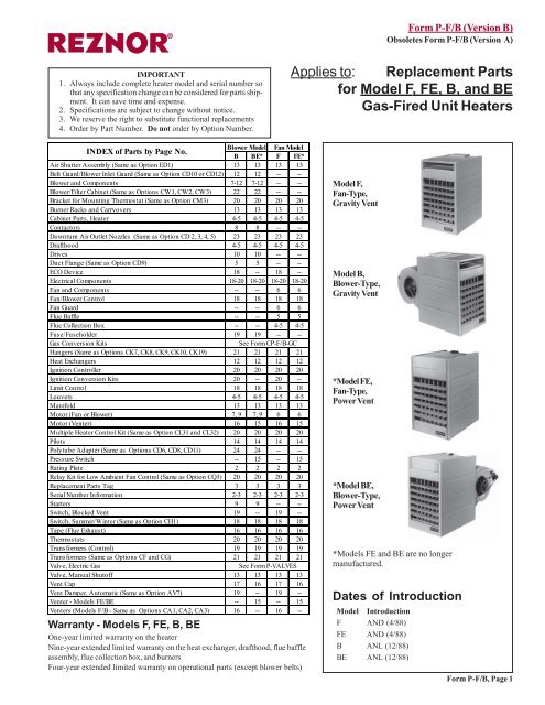
IMPORTANT<br />
1. Always include complete heater model <strong>and</strong> serial number so<br />
that any specification change can be considered <strong>for</strong> parts shipment.<br />
It can save time <strong>and</strong> expense.<br />
2. Specifications are subject to change without notice.<br />
3. We reserve the right to substitute functional replacements<br />
4. Order by Part Number. Do not order by Option Number.<br />
®<br />
INDEX of <strong>Parts</strong> by Page No.<br />
Blower <strong>Model</strong><br />
B <strong>BE</strong>*<br />
Fan <strong>Model</strong><br />
F <strong>FE</strong>*<br />
Air Shutter Assembly (Same as Option ED1) 13 13 13 13<br />
Belt Guard/Blower Inlet Guard (Same as Option CD10 or CD12) 12 12 -- --<br />
Blower <strong>and</strong> Components 7-12 7-12 -- --<br />
Blower/Filter Cabinet (Same as Options CW1, CW2, CW3) 22 22 -- --<br />
Bracket <strong>for</strong> Mounting Thermostat (Same as Option CM3) 20 20 20 20<br />
Burner Racks <strong>and</strong> Carryovers 13 13 13 13<br />
Cabinet <strong>Parts</strong>, Heater 4-5 4-5 4-5 4-5<br />
Contactors 8 8 -- --<br />
Downturn Air Outlet Nozzles (Same as Option CD 2, 3, 4, 5) 23 23 23 23<br />
Drafthood 4-5 4-5 4-5 4-5<br />
Drives 10 10 -- --<br />
Duct Flange (Same as Option CD9) 5 5 -- --<br />
ECO Device 18 -- 18 --<br />
Electrical Components 18-20 18-20 18-20 18-20<br />
Fan <strong>and</strong> Components -- -- 6 6<br />
Fan/Blower Control 18 18 18 18<br />
Fan Guard -- -- 6 6<br />
Flue Baffle -- -- 5 5<br />
Flue Collection Box -- -- 4-5 4-5<br />
Fuse/Fuseholder 19 19 -- --<br />
<strong>Gas</strong> Conversion Kits<br />
See Form CP-F/B-GC<br />
Hangers (Same as Options CK7, CK8, CK9, CK10, CK19) 21 21 21 21<br />
Heat Exchangers 12 12 12 12<br />
Ignition Controller 20 20 20 20<br />
Ignition Conversion Kits 20 -- 20 --<br />
Limit Control 18 18 18 18<br />
Louvers 4-5 4-5 4-5 4-5<br />
Manifold 13 13 13 13<br />
Motor (Fan or Blower) 7, 9 7, 9 6 6<br />
Motor (Venter) 16 15 16 15<br />
Multiple Heater Control Kit (Same as Option CL31 <strong>and</strong> CL32) 20 20 20 20<br />
Pilots 14 14 14 14<br />
Polytube Adapter (Same as Options CD6, CD8, CD11) 24 24 -- --<br />
Pressure Switch -- 15 -- 15<br />
Rating Plate 2 2 2 2<br />
Relay Kit <strong>for</strong> Low Ambient Fan Control (Same as Option CQ3) 20 20 20 20<br />
<strong>Replacement</strong> <strong>Parts</strong> Tag 3 3 3 3<br />
Serial Number In<strong>for</strong>mation 2-3 2-3 2-3 2-3<br />
Starters 9 9 -- --<br />
Switch, Blocked Vent 19 -- 19 --<br />
Switch, Summer/Winter (Same as Option CH1) 18 18 18 18<br />
Tape (Flue Exhaust) 16 16 16 16<br />
Thermostats 20 20 20 20<br />
Trans<strong>for</strong>mers (Control) 19 19 19 19<br />
Trans<strong>for</strong>mers (Same as Options CF <strong>and</strong> CG) 21 21 21 21<br />
Valve, Electric <strong>Gas</strong><br />
See Form P-VALVES<br />
Valve, Manual Shutoff 13 13 13 13<br />
Vent Cap 17 16 17 16<br />
Vent Damper, Automatic (Same as Option AV7) 19 -- 19 --<br />
Venter - <strong>Model</strong>s <strong>FE</strong>/<strong>BE</strong> -- 15 -- 15<br />
Venters (<strong>Model</strong>s F/B - Same as Options CA1, CA2, CA3) 16 -- 16 --<br />
Warranty - <strong>Model</strong>s F, <strong>FE</strong>, B, <strong>BE</strong><br />
One-year limited warranty on the heater<br />
Nine-year extended limited warranty on the heat exchanger, drafthood, flue baffle<br />
assembly, flue collection box, <strong>and</strong> burners<br />
Four-year extended limited warranty on operational parts (except blower belts)<br />
Form P-F/B (Version B)<br />
Obsoletes Form P-F/B (Version A)<br />
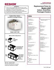
Applies to: <strong>Replacement</strong> <strong>Parts</strong><br />
<strong>for</strong> <strong>Model</strong> F, <strong>FE</strong>, B, <strong>and</strong> <strong>BE</strong><br />
<strong>Gas</strong>-<strong>Fired</strong> Unit Heaters<br />
<strong>Model</strong> F,<br />
Fan-Type,<br />
Gravity Vent<br />
<strong>Model</strong> B,<br />
Blower-Type,<br />
Gravity Vent<br />
*<strong>Model</strong> <strong>FE</strong>,<br />
Fan-Type,<br />
Power Vent<br />
*<strong>Model</strong> <strong>BE</strong>,<br />
Blower-Type,<br />
Power Vent<br />
*<strong>Model</strong>s <strong>FE</strong> <strong>and</strong> <strong>BE</strong> are no longer<br />
manufactured.<br />
Dates of Introduction<br />
<strong>Model</strong> Introduction<br />
F AND (4/88)<br />
<strong>FE</strong> AND (4/88)<br />
B ANL (12/88)<br />
<strong>BE</strong> ANL (12/88)<br />
Form P-F/B, Page 1
Example of a Rating Plate<br />
REZNOR<br />
MERCER, PA. USA 16137<br />
MADE IN MEXICO<br />
UNIT HEATER<br />
CATEGORY III<br />
FOR INDUSTRIAL/COMMERCIAL USE ONLY<br />
ANSI Z83.8a CGA 2.6-M98 UNIT HEATER<br />
MODEL [ B ] [ C ]<br />
SERIAL NO. BAA 65W7N12345<br />
[ D ] VOLTS [ D ] PH [ D ] HZ MAXIMUM TOTAL INPUT [ D ] AMPS<br />
TYPE OF GAS: [ E ]<br />
ORIFICE SIZE [ F ] DRILL HAS <strong>BE</strong>EN FACTORY ADJUSTED<br />
FOR USE AT [ H ] <strong>FE</strong>ET [ G ] METERS OF ALTITUDE.<br />
SEA LEVEL ALT. ADJUSTED<br />
NORMAL INPUT [ I ] [ J ]BTU/HR.<br />
THERMAL OUTPUT CAPACITY [ K ] [ L ]BTU/HR.<br />
MINIMUM INPUT (-2 MODELS) [ M ] [ N ]BTU/HR.<br />
NORMAL MANIFOLD PRESSURE [ O ] IN.W.C.<br />
MIN. PERMISSIBLE GAS SUPPLY PRESSURE<br />
FOR PURPOSE OF INPUT ADJUSTMENT.<br />
[ P ] IN.W.C.<br />
CLEARANCES TO COMBUSTIBLE CONSTRUCTION: TOP-[ Q ]", FLUE<br />
CONNECTION-6", LEFT SIDE-18", RIGHT SIDE-18", BOTTOM-12"<br />
EXCEPT WHEN SUPPLIED WITH OPTIONAL DOWNTURN NOZZLE<br />
BOTTOM IS 42".<br />
FOR ALTERNATE INSTALLATIONS USE THE LATEST EDITIONS OF THE<br />
APPROPRIATE STANDARD LISTED <strong>BE</strong>LOW / INSTALL IN ACCORDANCE<br />
WITH REQUIREMENTS OF ENFORCING AUTHORITIES:<br />
FOR AIRCRAFT HANGARS USE STANDARD ANSI/NFPA 409<br />
FOR PARKING STRUCTURES USE STANDARD ANSI/NFPA 88A<br />
FOR REPAIR GARAGES USE STANDARD ANSI/NFPA 88B<br />
THIS UNIT IS NOT FOR USE WITH DUCTS.<br />
THIS UNIT IS NOT FOR USE WITH FILTERS.<br />
THIS UNIT IS FOR USE WITH NATURAL GAS AND PROPANE. A<br />
CONVERSION KIT AS SUPPLIED BY THE MANUNFACTURER, SHALL <strong>BE</strong><br />
USED TO CONVERT THIS UNIT HEATER TO THE ALTERNATE FUEL.<br />
Example of a <strong>Replacement</strong> <strong>Parts</strong> Tag<br />
<strong>Replacement</strong> parts tags on unit heaters are <strong>for</strong> your convenience in identifying replacement part numbers. Always give the<br />
full <strong>Model</strong> No., Serial No., <strong>and</strong> Part No. with description when ordering replacement parts.<br />
COMMON REPLACEMENT PARTS FOR:<br />
MODEL: <strong>FE</strong>100<br />
SERIAL NUM<strong>BE</strong>R: BAA65W7N12345<br />
WHEN ORDERING PARTS, ALWAYS GIVE THE FULL MODEL NUM<strong>BE</strong>R AND SERIAL NUM<strong>BE</strong>R.<br />
Fan or Blower Motor ....... 95548<br />
Fan Blade ....................... 41004<br />
Fan Control ..................... 123976<br />
Limit Control ................... 45602<br />
Trans<strong>for</strong>mer .................... 131988<br />
Pilot ................................. 97534<br />
<strong>Gas</strong> Valve ........................ 170609<br />
Heat Exchanger .............. 102285<br />
WARNING<br />
ALL PARTS ARE FOR USE WITH THE FUEL IDENTIFIED ON THE UNIT RATING PLATE. IF THE UNIT HAS<br />
<strong>BE</strong>EN CONVERTED TO OTHER FUELS, CHECK WITH THE DEALER FOR PROPER FUEL-CARRYING<br />
PARTS. INSTALLATION OF IMPROPER PARTS CAN CAUSE DEATH OR INJURY OR PROPERTY LOSS.<br />
Form P-F/B, Page 2<br />
Key to Rating Plate In<strong>for</strong>mation:<br />
B = <strong>Model</strong> No. (Size)<br />
C = Month <strong>and</strong> Year of Manufacture<br />
D = Volts, Phase, Hertz <strong>and</strong> Maximum Total Input Amps<br />
E = Type of <strong>Gas</strong> (Natural or Propane)<br />
F = Burner Orifice Size<br />
G <strong>and</strong> H = Elevation in Feet <strong>and</strong> Meters<br />
I = Normal Input (BTUH) at Sea Level<br />
J = BTUH Input Adjusted <strong>for</strong> Altitude<br />
K = Thermal Output Capacity (BTUH) at Sea Level<br />
L = BTUH Output Adjusted <strong>for</strong> Altitude<br />
M = Minimum Input (BTUH) at Sea Level<br />
N = BTUH Minimum Input Adjusted <strong>for</strong> Altitude<br />
O = Normal Manifold Pressure (in. w.c.)<br />
P = Minimum <strong>Gas</strong> Supply Pressure (in w.c.)<br />
Q = Top Clearance (inches)<br />
Serial No. Explanation<br />
Example:<br />
BAA 65 W7 N 12345<br />
1 2 3 4 5<br />
Key:<br />
1 = Date of manufacturer (see table on page 3)<br />
2 = Type of Pilot (Refer to Form P-VALVES)<br />
3 = <strong>Gas</strong> Valve (Refer to Form P-VALVES)<br />
4 = Type of <strong>Gas</strong> (N = Natural; L = Propane)<br />
5 = Consecutive number of heater made (identification only)<br />
<strong>Model</strong> No. Suffixes:<br />
-S = Stainless steel heat exchanger<br />
-2 = Two-stage gas valve<br />
-E = Intermittent spark ignition (<strong>Model</strong>s F/B)<br />
-H = High altitude
First Element of the Serial Number - Date of Manufacture<br />
Year Jan Feb Mar Apr May June July Aug Sept Oct Nov Dec<br />
1988 ANA ANB ANC AND ANE ANF ANG ANH ANI ANJ ANK ANL<br />
1989 AOA AOB AOC AOD AOE AOE AOG AOH AOI AOJ AOK AOL<br />
1990 APA APB APC APD APE APF APG APH API APJ APK APL<br />
1991 AQA AQB AQC AQD AQE AQF AQG AQH AQI AQJ AQK AQL<br />
1992 ARA ARB ARC ARD ARE ARF ARG ARH ARI ARJ ARK ARL<br />
1993 ASA ASB ASC ASD ASE ASF ASG ASH ASI ASJ ASK ASL<br />
1994 ATA ATB ATC ATD ATE ATF ATG ATH ATI ATJ ATK ATL<br />
1995 AUA AUB AUC AUD AUE AUF AUG AUH AUI AUJ AUK AUL<br />
1996 AVA AVB AVC AVD AVE AVF AVG AVH AVI AVJ AVK AVL<br />
1997 AWA AWB AWC AWD AWE AWF AWG AWH AWI AWJ AWK AWL<br />
1998 AXA AXB AXC AXD AXE AXF AXG AXH AXI AXJ AXK AXL<br />
1999 AYA AYB AYC AYD AYE AYF AYG AYH AYI AYJ AYK AYL<br />
2000 AZA AZB AZC AZD AZE AZF AZG AZH AZI AZJ AZK AZL<br />
2001 BAA BAB BAC BAD BAE BAF BAG BAH BAI BAJ BAK BAL<br />
2002 BBA BBB BBC BBD B<strong>BE</strong> BBF BBG BBH BBI BBJ BBK BBL<br />
2003 BCA BCB BCC BCD BCE BCF BCG BCH BCI BCJ BCK BCL<br />
2004 BDA BDB` BDC BDD BDE BDF BDG BDH BDI BDJ BDK BDL<br />
2005 <strong>BE</strong>A <strong>BE</strong>B <strong>BE</strong>C <strong>BE</strong>D <strong>BE</strong>E <strong>BE</strong>F <strong>BE</strong>G <strong>BE</strong>H <strong>BE</strong>I <strong>BE</strong>J <strong>BE</strong>K <strong>BE</strong>L<br />
2006 BFA BFB BFC BFD B<strong>FE</strong> BFF BFG BFH BFI BFJ BFK BFL<br />
2007 BGA BGB BGC BGD BGE BGF BGG BGH BGI BGJ BGK BGL<br />
2008 BHA BHB BHC BHD BHE BHF BHG BHH BHI BHJ BHK BHL<br />
2009 BIA BIB BIC BID BIE BIF BIG BIH BII BIJ BIK BIL<br />
2010 BJA BJB BJC BJD BJE BJF BJG BJH BJI BJJ BJK BJL<br />
2011 BKA BKB BKC BKD BKE BKF BKG BKH BKI BKJ BKK BKL<br />
2012 BLA BLB BLC BLD BLE BLF BLG BLH BLI BLJ BLK BLL<br />
2013 BMA BMB BMC BMD BME BMF BMG BMH BMI BMJ BMK BML<br />
2014 BNA BNB BNC BND BNE BNF BNG BNH BNI BNJ BNK BNL<br />
2015 BOA BOB BOC BOD BOE BOF BOG BOH BOI BOJ BOK BOL<br />
2016 BPA BPB BPC BPD BPE BPF BPG BPH BPI BPJ BPK BPL<br />
2017 BQA BQB BQC BQD BQE BQF BQG BQH BQI BQJ BQK BQL<br />
2018 BRA BRB BRC BRD BRE BRF BRG BRH BRI BRJ BRK BRL<br />
2019 BSA BSB BSC BSD BSE BSF BSG BSH BSI BSJ BSK BSL<br />
2020 BTA BTB BTC BTD BTE BTF BTG BTH BTI BTJ BTK BTL<br />
Literature References by Form No.:<br />
All literature is available <strong>for</strong> viewing or downloading on www.RezSpec.com<br />
Form Applies to Installation Instructions <strong>for</strong>: Form P/N<br />
I-F/B F/B Heater Installation Manual 98126<br />
I-F/B-HV F/B 250, 300, 400 Horizontal/Vertical Vent Outlet 102860<br />
I-F/B-HV125 F/B125 Horizontal/Vertical Vent Outlet 132794<br />
I-F/B-PV F/B Optional Power Venter 97967<br />
I-<strong>FE</strong>/<strong>BE</strong> <strong>FE</strong>/<strong>BE</strong> Heater Installation Manual 98807<br />
I-F/B-AS F/B/<strong>FE</strong>/<strong>BE</strong> Optional Air Shutters 98239<br />
I-B-BF B/<strong>BE</strong> Optional Blower Cabinet 99714<br />
I-B-BG B/<strong>BE</strong> Optional Guards 101542<br />
I-B-DF B/<strong>BE</strong> Optional Duct Flange 101192<br />
I-F/B-DN F/B/<strong>FE</strong>/<strong>BE</strong> Optional Downturn Air Nozzles 97926<br />
CP-F/B-GC F/B/<strong>FE</strong>/<strong>BE</strong> <strong>Gas</strong> Conversion Kits 99279<br />
I-F/B-LA F/B/<strong>FE</strong>/<strong>BE</strong> w/1-stg gas valve Optional Low Ambient Fan Control Relay 131134<br />
I-B-PF B/<strong>BE</strong> Optional Polytube Adapters <strong>for</strong> Floor-Level Units 101694<br />
I-B-PS B/<strong>BE</strong> Optional Polytube Adapters <strong>for</strong> Suspended Units 101500<br />
I-F/B-R F/<strong>FE</strong>/B/<strong>BE</strong> Optional Relays 98149<br />
I-B-SWB B/<strong>BE</strong> Optional Summer Fan Switch 101678<br />
I-F-SWF F/<strong>FE</strong> Optional Summer Fan Switch 98294<br />
I-F/B-VL F/<strong>FE</strong>/B/<strong>BE</strong> Optional Vertical Louvers 97925<br />
I-F/B-X F/<strong>FE</strong>/B/<strong>BE</strong> Optional Stepdown Trans<strong>for</strong>mers 102265<br />
P-VALVES All Ignition Controllers, Valves, & Serial No. Identification N/A<br />
CP-F/B-IGN F/B Ignition Conversion Kits 100550<br />
Form P-F/B, Page 3
Cabinet <strong>Parts</strong><br />
<strong>Model</strong> F/B Drafthoods (heaters manufactured beginning 10/89)<br />
Sizes 25-100, 130-200<br />
Original Vertical-only drafthood<br />
(<strong>Model</strong>s F&B manufactured be<strong>for</strong>e 10/89)<br />
Replace with Codes 19A, 19B, 19C, 19D<br />
illustrated at the top of the page<br />
4 Outer Side Panel - left<br />
1 Top<br />
Front<br />
16B Lower Stiffening<br />
Channel<br />
(<strong>BE</strong>)<br />
2 Bottom Front<br />
Form P-F/B, Page 4<br />
®<br />
25 <strong>Reznor</strong> Logo Label<br />
19A (1-pc<br />
drafthood)<br />
16A Upper Stiffening<br />
Channel (B&<strong>BE</strong> <strong>Model</strong>s)<br />
12 Louver<br />
Frame Assy<br />
7 Bottom Pan<br />
19B - Flue<br />
Collar<br />
Assembly<br />
15 Inner Side<br />
Panel- right<br />
14 Inner Side<br />
Panel - left<br />
6 Wiring<br />
Access<br />
Panel Assy<br />
Drafthood<br />
Left Rear<br />
19B Flue<br />
Collar Assembly<br />
Sizes 125, 250-400<br />
16B<br />
19D Cover<br />
21 Flue Collection<br />
Box Assembly<br />
(<strong>FE</strong> & <strong>BE</strong> <strong>Model</strong>s)<br />
9 Fan Back<br />
(F&<strong>FE</strong> <strong>Model</strong>s)<br />
5 Fan/Limit<br />
Access Panel<br />
3 Outer Side<br />
Panel - right<br />
Code 20 -<br />
Flue Baffle<br />
Assembly -<br />
Gravity<br />
Vented<br />
<strong>Model</strong>s<br />
18B Horizontal Barrier<br />
18A Vertical<br />
Barrier<br />
Drafthood Front<br />
19C Flue<br />
Collar<br />
Support<br />
Drafthood<br />
Right Rear<br />
19A 3-pc<br />
Drafthood<br />
Assembly<br />
23 Adapter Back<br />
(B&<strong>BE</strong> <strong>Model</strong>s)<br />
10 Back<br />
Panel<br />
(B&<strong>BE</strong>)
Code Description 25 50 75 100 125<br />
Size<br />
130 165 200 250 300 400<br />
1 Top Front 94661 94662 94663 94665 94663 94664 94665 94666 94667<br />
2 Bottom Front 94668 94669 94670 94672 94670 94671 94672 94673 94674<br />
3 Right Side Outer Panel<br />
104968 104970<br />
4 Left Side Outer Panel<br />
104969 104971<br />
5 Fan/Limit Access Panel<br />
94898<br />
6 Wiring Access Panel<br />
94897<br />
7 Bottom Panel 94687 94688 94689 94690 131607 94691 94692 94693 94694 94695 94696<br />
8 Right Hinge Pin Assembly <strong>for</strong> Bottom Panel<br />
96445<br />
Left Hinge Pin Assembly <strong>for</strong> Bottom Panel<br />
99351<br />
9 Fan Back Panel - Fan <strong>Model</strong> 94675 94676 161181 161184 N/A 161182 94680 161183 94682<br />
10 Back Panel - Blower <strong>Model</strong> 99830 99831 99832 99835 99833 99834 99835 99836 99837<br />
11 Latch Fastener <strong>for</strong> Fan Back (2) - used prior to 2/95<br />
96435<br />
12 Horizontal Louver Assembly 94851 94855 94857 131803 94859 94863 94865 94867 94869<br />
13 Vertical Louver Assembly (Same as Option CD1) 98500 98501 98502 136863 98503 98504 98505 98506 98507<br />
13A Vertical Louver Top/Bottom Member only 97852 97853 97854 97856 97854 97855 97856 97857 97858<br />
13B Vertical Louver only<br />
95937 95938<br />
(4) (4) (4) (4) (6) (4) (6) (6) (8) (8) (10)<br />
14 Inner Left Side Panel<br />
94842 94837<br />
15 Inner Right Side Panel (includes conduit Fan <strong>Model</strong>s<br />
99025 99026<br />
nut plate <strong>for</strong> electrical supply) Blower <strong>Model</strong>s<br />
102346 102347<br />
16A Upper Stiffening Channel Blower <strong>Model</strong>s<br />
100867 (2) 100869 (2)<br />
16B Lower Stiffening Channel Blower <strong>Model</strong>s<br />
100868 (2) 100870 (2)<br />
17 Air Deflectors (not illustrated)<br />
Horizontal - Right Side Fan <strong>Model</strong>s -- -- -- -- -- 96141<br />
94899<br />
Vertical - Right Side All <strong>Model</strong>s 96714 -- -- -- -- -- -- -- -- -- --<br />
Horizontal - Left Side Fan <strong>Model</strong>s -- 96140 -- -- 96140 96141 94900<br />
Vertical - Left Side All <strong>Model</strong>s 96714 -- -- -- -- -- -- -- -- -- --<br />
18A Vertical Barrier<br />
94749 94750<br />
18B Horizontal Barrier<br />
94751<br />
19A Drafthood <strong>for</strong> Gravity Vent Sizes 25-200 102449 102450 102451 131608 102838 102839 102840 -- -- --<br />
(See Drafthood Assembly <strong>for</strong> Gravity Vent Sizes 250-400 -- -- -- -- -- -- -- -- 101909 101910<br />
NOTE Components: Drafthood Front -- -- -- -- -- -- -- -- 105310 105311<br />
Below) Drafthood Right Rear -- -- -- -- -- -- -- -- 101903 101904<br />
Drafthood Left Rear -- -- -- -- -- -- -- -- 101906 101907<br />
Screws, #10 x 1/2" sheetmetal -- -- -- -- -- -- -- -- 51489 (6)<br />
19B Flue Collar Assembly - Gravity Vent M odels 102363 102364 102365 132765 102844 102845 102846 102847<br />
19C Flue Collar Support - Gravity Vent <strong>Model</strong>s -- -- -- -- 131992 -- -- --<br />
102857<br />
19D Cover <strong>for</strong> Horizontal/Vertical Vent -- -- -- -- 132764 -- -- --<br />
102855<br />
(On sizes 25-100 <strong>and</strong> 130-200, the cover <strong>and</strong> flue collar assembly are one piece)<br />
20 Flue Baffle Assembly - Gravity Vent M odels 100859 100886 100887 100860 131811 100861 100862 100863 100864 100865 100866<br />
21 Flue Collection Box Assembly - Power Vent <strong>Model</strong>s 97744 97746 97747 131804 97748 97749 97750 97751 97752 97753<br />
22A Flue Baffle - Power Vent <strong>Model</strong>s -- -- 97783 97784 134766 97785 97786 97787 101008 101009 101010<br />
22B Flue Baffle Clamp - Power Vent <strong>Model</strong>s -- --<br />
98196<br />
23 Adapter Back Assy including Baffles Blower <strong>Model</strong>s 100871 100872 100873 131975 100874 100875 100876 100877<br />
100878<br />
24 Duct Flange Kit (Same as Option CD9) Blower <strong>Model</strong>s 101194 101195 101501 135591 101196 101197 101198 101199 101200<br />
24A Duct Flange Top <strong>and</strong> Bottom <strong>Parts</strong> in Opts 101155 101156 101157 101159 101157 101158 101159 101160 101161<br />
24B Duct Flange Sides CD9 <strong>and</strong> AX4 101163 101163 101163 101163 101164 101164 101164 101164 101164<br />
25A <strong>Reznor</strong> Logo Label<br />
196690<br />
25B Tawny Beige Touch-up Paint, 10 oz spray can<br />
37919<br />
25C Maroon touch-up Paint, 12 oz apray can<br />
207432<br />
NOTE: Effective 4/1/91, all gravity-vent <strong>Model</strong> F <strong>and</strong> B heaters include a blocked vent system requiring holes in the drafthood. When replacing a<br />
drafthood on a heater without a blocked vent switch, these holes will not affect heater operation.<br />
Code 13 - Vertical<br />
Louver Assembly<br />
(Same as Option CD1)<br />
On fan models,<br />
do not use<br />
vertical louvers<br />
with optional<br />
discharge<br />
nozzles.<br />
Sheetmetal<br />
Screw<br />
13B Vertical<br />
Louver<br />
(left side)<br />
Vertical<br />
Louver<br />
(right side)<br />
Sheetmetal<br />
Screw<br />
13A Bottom<br />
Member<br />
Top Member<br />
Top Front<br />
Panel<br />
Bottom Front Panel<br />
Code 8 -<br />
Hinge<br />
Pin Assy<br />
Code 11 - Latch<br />
Fastener <strong>for</strong> Fan<br />
Back (used on<br />
heaters mfgd<br />
prior to 2/95)<br />
Code 24 - Duct Flange <strong>Parts</strong> (Same as Option CD9;<br />
components used in Option AX4)<br />
Form P-F/B, Page 5
Fan Components -- <strong>Model</strong>s F <strong>and</strong> <strong>FE</strong><br />
Code Description 25 50 75 100 125<br />
Size<br />
130 165 200 250 300 400<br />
26A Full Fan Guard 110907 110908 110910 132363 110910 136209 110912 176647 176648<br />
<strong>Model</strong> <strong>FE</strong> illustrating one-piece Fan<br />
Guard<br />
29<br />
28<br />
26A<br />
(See Notes below) (replaces<br />
110911)<br />
Form P-F/B, Page 6<br />
Fan Guard Notes<br />
(replaces 131404 <strong>and</strong><br />
110914)<br />
<strong>Model</strong> Date of Type of St<strong>and</strong>ard St<strong>and</strong>ard Available Carton<br />
Manufacture Fan Guard Carton Optional Marking<br />
Marking Fan Guard with Option<br />
F 4/88 - 10/90 Lower Half only None Upper Half Upper Fan Guard<br />
After 10/90 One-Piece Full Full Fan None N/A<br />
Fan Guard Guard<br />
<strong>FE</strong> 4/88 - 10/89 Lower Half only None Upper Half Upper Fan Guard<br />
10/89 - 10/90 Both Upper <strong>and</strong> Upper Fan None N/A<br />
Lower Halves Guard<br />
After 10/90 One-Piece Full Fan None N/A<br />
Full Fan Guard Guard<br />
(replaces<br />
110915 &<br />
131405)<br />
26B Fan Guard Plate (2) -- -- -- -- 133977 -- 133978 --<br />
Fan Guard Screws w/Washer -- -- -- 96450 (4)<br />
#10-32 1/2" lg Hex Hd Screw<br />
26D Fan Guard Isolator Assy (4) -- -- -- -- 96451 -- 96451 --<br />
26E Washer <strong>for</strong> Code 26D (4) -- -- -- -- 96452 -- 96452 --<br />
27 Motor Adapter Plate -- -- -- -- 96452 -- 96452 --<br />
28 Fan Motor, 96286 96287 96288 95546 147913 156275<br />
115/1/60, Open<br />
Univers al Univers al Univers al 1/30HP A. O.<br />
1/6HP 1/4HP A.O. 1/ 2HP<br />
#JA2C377N # JA2N199N #JA2R238N Smith #326P 139<br />
A.O. Smith<br />
Smith # F 48H01A13<br />
#F42A51 (replaces<br />
A13 95545)<br />
Fan Motor, -- -- -- --<br />
208/230/1/60, Open 1/6HP A.O. Smith #322P943 1/2HP Fasco #7128-0341<br />
Fan Motor, 96286 102381 --<br />
115/1/60, Enclosed Universal Universal #JA2S128N 1/8HP A.O. Smith #322P986 1/6HP A.O.<br />
#JA2C377<br />
Smith<br />
M<br />
#F48G56A13<br />
Fan Motor, .018HP, 115/1,<br />
Universal #JF2K010N A.O. Smith #92AC154 Assy including motor P/N 155063<br />
School Option (Opt AL2B)<br />
<strong>for</strong> <strong>Model</strong> F50 only<br />
-- 174403 -- -- -- -- -- -- -- -- --<br />
29 Fan Blades 132465 129853 96379 41004 131970 104692 96380 96381 96382 96383 96384<br />
(For proper shaft placement, Revcor Revcor Revcor Lau Revcor Revcor Revcor Lau #F10 Lau Lau #F10 Lau #F-12<br />
see Table in Fan Guard Notes #01005-18 #011005- #G1203-30 #FP- #T160 #T1404- G1603-40 H8.7 20-24 #F10 H8.7 22-36 H8.7 24-36<br />
below)<br />
(replaces 34 (replaces<br />
1437 3-32 40<br />
H8.7 22-<br />
Fan Blades, 5/16" bore, 10"<br />
96377 ) 96378 )<br />
(replaces<br />
48692)<br />
26<br />
dia, 5 blades, 34o 176151<br />
26C<br />
96450 (4)<br />
113275 (8)<br />
96451<br />
96452<br />
176523<br />
95548<br />
95547<br />
1/20HP<br />
97809 122665<br />
100992 102380<br />
137044<br />
1/4HP (replaces<br />
115866)<br />
Fan Motor, 230/1/50 Hertz<br />
112675 121277 172794<br />
(Opt AK11) <strong>Model</strong> F only<br />
pitch,<br />
School Option (Opt AL2B)<br />
<strong>for</strong> <strong>Model</strong> F50 only<br />
-- 129853 -- -- -- -- -- -- -- -- --<br />
Fan Guard <strong>Replacement</strong> - The upper <strong>and</strong> lower fan guard halves are no longer available.<br />
If adding an "upper half" or replacing a fan guard, it is necessary to install the full fan guard<br />
(Code 24). To make this replacement, follow these instructions.<br />
1. If the heater is installed, turn off the gas <strong>and</strong> disconnect the electric power.<br />
2. Remove the left outer side panel (left when facing the rear of the unit). Disconnect the fan<br />
motor wires.<br />
3. If present, remove the tension-mounted upper half fan guard.<br />
4. Remove the four screws <strong>for</strong> attaching the fan guard. Remove the lower half fan guard, the<br />
motor, <strong>and</strong> the fan blade.<br />
5. Assemble the new full fan guard, the motor <strong>and</strong> the fan blade. To Assure proper grounding<br />
of the motor, it is important that the same hardware be used <strong>for</strong> attaching the motor to the<br />
fan guard as was used with the original guard.<br />
Be sure fan blade is in the same position on the shaft; see illustration <strong>and</strong> Table, page 7.
Fan Motor Spacing<br />
Size Electrical Supply Fan Blade P/N Set Screw Torque In-Lbs "A" Hub to Motor Spacing<br />
25 60 Hz<br />
50 Hz*<br />
132465<br />
8 + or - 10<br />
1-1/4"<br />
3-1/4"<br />
Motor<br />
50 60 Hz<br />
50 Hz*<br />
129853<br />
8 + or - 10<br />
3/8"<br />
3-1/4"<br />
Fan Hub<br />
75 60 Hz<br />
50 Hz*<br />
96379<br />
8 + or - 10<br />
1/8"<br />
3-1/4"<br />
100 41004<br />
125 50* 131970 120 + or - 10<br />
130 or 104692<br />
A<br />
165<br />
200<br />
60 Hz 96380<br />
96381<br />
2-1/2"<br />
250 96382<br />
150 + or - 10<br />
300 96383<br />
400 96384<br />
*Only gravity-vented F models are available with 50 Hz.<br />
Position the assembly on the heater. Attach the fan guard at the center mounts using the screws that held the old fan guard. (It is important that<br />
you use these specially designed screws because they will cut through the coating on the fan guard to provide a ground <strong>for</strong> the fan motor.)<br />
Rotate the fan blade to check <strong>for</strong> adequate clearance. If adjustment is required, loosen the mounting screws, re-position the fan guard, <strong>and</strong> tighten<br />
the screws. Rotate the fan blade <strong>and</strong> re-check <strong>for</strong> adequate clearance. Repeat this procedure until the assembly is positioned properly.<br />
6. Drill the required upper <strong>and</strong> lower mounting holes. Attach the new fan guard at all upper <strong>and</strong> lower mounting points using field-supplied sheet<br />
metal screws.<br />
7. Reconnect the fan motor wires <strong>and</strong> replace the outer side panel.<br />
8. Restore power to the heater <strong>and</strong> turn on the gas. Light following the instructions on the lighting instruction plate. Check <strong>for</strong> proper operation.<br />
Blower<br />
Components -<br />
<strong>Model</strong>s B <strong>and</strong> <strong>BE</strong><br />
25-100 with Direct<br />
Drive Motor<br />
33<br />
30B<br />
37<br />
33B<br />
33A<br />
32<br />
30<br />
30A<br />
36<br />
<strong>Model</strong> B with Direct<br />
Drive Motor<br />
Code Description 25 50<br />
Size<br />
75 100<br />
30 Blower assy including blower (Code 30A),<br />
mounting angle (Code 30B), <strong>and</strong> restrictors<br />
100897 100898<br />
100899<br />
30A Blower only including housing <strong>and</strong> wheel 82111, Lau #DD9-6AP<br />
43607, Lau #DD9-9AP<br />
30B Blower Mounting Angle<br />
100888 (2)<br />
31 Blower Washer 3/4" x 1-1/2"<br />
1087 (4)<br />
32 Direct Drive Motors, 115 volt<br />
201760, 1/6HP 201761, 1/3HP<br />
(replaces 100491) (replaces 100490)<br />
33 Capacitor<br />
101917 101918<br />
5MFD/370V (replaces 43614) 7.5MFD/370V (replaces 82095)<br />
33A Capacitor End Cap (Stone City #4522-07)<br />
82113<br />
33B Capacitor Strap Bracket (Stone City #1614)<br />
82114<br />
34 Washer 1-1/8" OD x 1/4" ID<br />
82450 (3)<br />
35 Screw #14 x 1-1/4" Slotted Hex<br />
82451 (3)<br />
36 Motor B<strong>and</strong><br />
51221<br />
37 Motor Support<br />
51223 (3)<br />
Form P-F/B, Page 7
Blower Components (cont'd)<br />
<strong>Model</strong>s B <strong>and</strong> <strong>BE</strong> 50-400 with Belt-Driven Motor<br />
<strong>Model</strong> <strong>BE</strong> with a Belt-Driven Motor<br />
42B<br />
Form P-F/B, Page 8<br />
44B<br />
Motor Contactor<br />
Blower<br />
Pulley<br />
Motor<br />
Belt<br />
44A<br />
42A<br />
Code 44A - Motor Adjustment Mounting Assy -<br />
used with less than 1HP Motor<br />
5/16-18 x 4” lg<br />
Hex Head Bolt<br />
5/16-18<br />
Lock Nut<br />
Motor Adjustment Mounting<br />
Assy - 1HP <strong>and</strong> larger motor<br />
Bolt, P/N<br />
16247(2)<br />
Right Support<br />
P/N 194121<br />
Code Description<br />
Sizes<br />
50-300 400<br />
47A Contactor, 115V, Furnas #42AF35AF (Important Note: If 119626 --<br />
replacing a Gould contactor, order complete contactor assy (replaces<br />
including a new enclosure, P/N 95527)<br />
93662)<br />
Contactor, 230V, Furnas #42AF35AG (Important Note: If 119627 (replaces<br />
replacing a Gould contactor, order complete contactor assy<br />
including a new enclosure, P/N 95528)<br />
93663)<br />
Contactor, 460V, 24V Coil, Furnas #42AF35AJ (Important 119625 (replaces<br />
Note: If replacing a Gould contactor, order complete contactor<br />
assy including a new enclosure, P/N 95526)<br />
93661)<br />
47B Contactor Enclosure (<strong>for</strong> use with Furnas contactor only)<br />
93917<br />
47C Contactor Enclosure Cover (<strong>for</strong> use with Furnas contactor only) 120302<br />
5/16 - 18<br />
Hex nut<br />
Rubber<br />
Grommet<br />
5/16-18 x 3/4” lg<br />
Square Head Bolt<br />
Code 45<br />
Motor Mounting<br />
Plate<br />
Code 47 - Motor Contactor with<br />
Cover Removed<br />
47A<br />
47B<br />
Bolt, P/N 16248<br />
Nut, P/N 6554 (10)<br />
Washer 1087 (8)<br />
Code 44B - Blower<br />
Motor Mounting<br />
Bracket<br />
Bolt,<br />
P/N<br />
12489<br />
(2)<br />
Left<br />
Support<br />
P/N<br />
194122<br />
Size<br />
Code Description 50 75 100 125 130/165 200 250/300 400<br />
42A Blower only<br />
100655, Lau #A9- 100656, Lau 1357, LAU 100657, Lau 100658, Lau 100659, Lau<br />
6ACD #A9-9A #10AC-10AC #A12-9ACD #A15-11ACD #A15-15ACD<br />
42B Blower Mounting Angle 100888 (2)<br />
131800 (2) 100889 (2) 100890 (2)<br />
42C Blower Bearings<br />
7310 (2) 10437 (2)<br />
43 Blower Washer 3/4" x 1-1/2" -- -- -- --<br />
1087 (4)<br />
44A Mtr Adjustment Bracket Assy - 3/4HP or less<br />
44411<br />
44B Blower Mtr Mounting Bracket - 3/4HP or less 102536<br />
102537 44409 102533 102534 102535<br />
45 Blower Mtr Mounting Plate - 1 HP <strong>and</strong> larger<br />
(plate only, see illustration <strong>for</strong> additional parts) -- -- -- -- 114545 194120 194118<br />
46 Key-1/4" square x 1-1/4" long<br />
16099<br />
47C
Belt-Driven Blower Motors <strong>and</strong> Motor Starters<br />
Motors that do not list a contactor <strong>and</strong> overload have internal overload protection <strong>and</strong> are used with a contactor (Code 47A, page 8). Motors in the<br />
tables below with a contactor (starter) <strong>and</strong> overload listed do not have internal overload protection <strong>and</strong> must be used with the motor starter <strong>and</strong><br />
overload. All motor starters must be ordered with a NEMA 1 enclosure, P/N 151207, GE#CLXE1A.<br />
Motor Service Power Eff Contactor <strong>Reznor</strong> Overload o.l. o.l. <strong>Reznor</strong><br />
Type HP FLA <strong>Model</strong> No. P/N volt ph Factor Factor<br />
% GE # P/N GE # min max P/N<br />
Open 1/4 4.6 BF2024 210611 120 1 1.35 - - - - - -<br />
Open 1/4 2.3 BF2024 210611 208 1 1.15 63 59 - - - - - -<br />
Open 1/4 2.3 BF2024 210611 240 1 1.15 63 59 - - - - - -<br />
Open 1/4 1.1 H200 115864 208 3 1.35 72 74 - - - - - -<br />
Open 1/4 1.4 H200 115864 240 3 1.35 72 74 - - - - - -<br />
Open 1/4 0.75 H200 115864 480 3 1.35 72 81 - - - - - -<br />
Open 1/3 6 BF2034 202091 120 1 1.35 - - - - - -<br />
Open 1/3 3 BF2034 202091 208 1 1.35 62.8 61.3 - - - - - -<br />
Open 1/3 3 BF2034 202091 240 1 1.35 62.8 61.3 - - - - - -<br />
Open 1/3 1.4 H260 115863 208 3 1.35 CL00A310T-L 151150 RTA1-G 1.00 1.50 151187<br />
Open 1/3 1.6 H260 115863 240 3 1.35 CL00A310T-S 151147 RTA1-H 1.30 1.90 151188<br />
Open 1/3 0.8 H260 115863 480 3 1.35 CL00A310T-U 151148 RTA1-F 0.65 1.10 151186<br />
Open 1/2 8.8 BF2054 102627 120 1 1.15 - - - - - -<br />
Open 1/2 5.1 BF2054 102627 208 1 1.15 - - - - - -<br />
Open 1/2 4.4 BF2054 102627 240 1 1.15 - - - - - -<br />
Open 1/2 2.5 H880 159183 208 3 1.25 - - - - - -<br />
Open 1/2 3 H880 159183 240 3 1.25 - - - - - -<br />
Open 1/2 1.5 H880 159183 480 3 1.25 - - - - - -<br />
Open 1/2 AOS - H991 202089 575 3<br />
Contact distributor or factory.<br />
Open 3/4 11 312P629 93548 120 1 1.25 - - - - - -<br />
Open 3/4 6.3 312P629 93548 208 1 1.25 - - - - - -<br />
Open 3/4 5.5 93548 240 1 1.25 - - - - - -<br />
Open 3/4 2.9 312P696 36951 208 3 1.25 - - - - - -<br />
Open 3/4 2.6 312P696 36951 240 3 1.25 - - - - - -<br />
Open 3/4 1.3 312P696 36951 480 3 1.25 - - - - - -<br />
Open 3/4 AOS - H992 202090 575 3<br />
Contact distributor or factory.<br />
Open 1 13 C523 13685 120 1 1.25 - - - - - -<br />
Open 1 7.5 C523 13685 208 1 1.25 - - - - - -<br />
Open 1 6.5 C523 13685 240 1 1.25 - - - - - -<br />
Open 1 3.7 H882 36580 208 3 1.15 79 - - - - - -<br />
Open 1 3.2 H882 36580 240 3 1.15 79 - - - - - -<br />
Open 1 1.6 H882 36580 480 3 1.15 79 - - - - - -<br />
Open 1 1.1 E1006 158175 575 3 1.15 82.5 CL00A310T-Y 151149 RTA1-G 1.00 1.50 151187<br />
Open 1.5 15 C621 194202 120 1 1.2 86.4 77.2 - - - - - -<br />
Open 1.5 7.8 C621 194202 208 1 1.2 86.4 77.2 - - - - - -<br />
Open 1.5 7.5 C621 194202 240 1 1.2 86.4 77.2 - - - - - -<br />
Open 1.5 5.6 H884 115859 208 3 1.15 66.4 78.6 - - - - - -<br />
Open 1.5 5 H884 115859 240 3 1.15 66.4 78.6 - - - - - -<br />
Open 1.5 2.8 H884 115859 480 3 1.15 66.4 78.6 - - - - - -<br />
Open 1.5 1.6 E1007 158162 575 3 1.15 85.3 86.3 CL00A310T-U 151148 RTA1-H 1.30 1.90 151188<br />
Open 2 20.4 V102 202581 120 1 1.15 81.8 77.5 - - - - - -<br />
Open 2 10 V102 202581 208 1 1.15 81.8 77.5 - - - - - -<br />
Open 2 10.2 V102 202581 240 1 1.15 81.8 77.5 - - - - - -<br />
Open 2 7 H886 159327 208 3 1.15 67 0.79 - - - - - -<br />
Open 2 6.6 H886 159327 240 3 1.15 67 0.79 - - - - - -<br />
Open 2 3.5 H886 159327 480 3 1.15 67 0.79 - - - - - -<br />
Open 2 2.1 E1008 158176 575 3 1.15 86 84.8 CL00A310T-Y 151149 RTA1-J 1.90 2.70 151189<br />
Open 3 14 B735 111560 208 1 1.15 94.5 80.3 CL02A310T-L 151159 RTA1-P 10.00 16.00 151194<br />
Open 3 12.4 B735 111560 240 1 1.15 94.5 80.3 CL01A310T-S 151152 RTA1-P 10.00 16.00 151194<br />
Open 3 9 H845 159185 208 3 1.15 - - - - - -<br />
Open 3 8.6 H845 159185 240 3 1.15 - - - - - -<br />
Open 3 4.3 H845 159185 480 3 1.15 - - - - - -<br />
Open 3 3.6 H954 120019 575 3 1.15 80.3 83.8 CL00A310T-Y 151149 RTA1-K 2.50 4.10 151190<br />
Open 3 8.9 M3158 152002 208 3 80 - - - - - -<br />
Open 3 8 M3158 152002 240 3 80 - - - - - -<br />
Open 3 4 M3158 152002 480 3 80 - - - - - -<br />
Open 5 28 V211 111562 208 1 1.15 79.2 78.9 - - - - - -<br />
Open 5 26 V211 111562 240 1 1.15 79.2 78.9 - - - - - -<br />
Open 5 13.4 196033 113371 208 3 1.15 87.2 78.9 CL01A310T-L 151155 RTA1-P 10.00 16.00 151194<br />
Open 5 13.2 196033 113371 240 3 1.15 87.2 85 CL01A310T-S 151152 RTA1-P 10.00 16.00 151194<br />
Open 5 6.6 196033 113371 480 3 1.15 87.2 85 CL00A310T-1 151275 RTA1-M 5.50 8.50 151192<br />
Open 5 5.4 H956 120020 575 3 1.15 85.9 85 CL00A310T-Y 151149 RTA1-L 4.00 6.30 151191<br />
Form P-F/B, Page 9
Blower Components (cont'd)<br />
Belt-Driven Blower Motors <strong>and</strong> Motor Starters (cont'd)<br />
Motors (cont'd) Service Power Eff Contactor <strong>Reznor</strong> Overload o.l. o.l. <strong>Reznor</strong><br />
Type HP FLA <strong>Model</strong> No. P/N volt ph Factor Factor % GE # P/N GE # min max P/N<br />
TEFC 1/4 3.6 STOCK #904 105566 120 1 1 - - - - - -<br />
TEFC 1/4 2.2 108152 16074 208 1 1.35 - - - - - -<br />
TEFC 1/4 1.9 108152 16074 240 1 1.35 - - - - - -<br />
TEFC 1/4 1.6 125439 16075 208 3 1 61.9 72.1 - - - - - -<br />
TEFC 1/4 1.4 125439 16075 240 3 1 61.9 72.1 - - - - - -<br />
TEFC 1/4 0.7 125439 16075 480 3 1 61.9 72.1 - - - - - -<br />
TEFC 1/3 4.6 STOCK #906 115861 120 1 1 68.5 72.1 - - - - - -<br />
TEFC 1/3 2.3 C151 159501 208 1 1 67.2 69.5 - - - - - -<br />
TEFC 1/3 2.4 C151 159501 240 1 1 67.2 69.5 - - - - - -<br />
TEFC 1/3 1.2 H261 105567 208 3 1.15 79.5 CL00A310T-L 151150 RTA1-G 1.00 1.50 151187<br />
TEFC 1/3 1.2 H261 105567 240 3 1.15 79.5 CL00A310T-S 151147 RTA1-G 1.00 1.50 151187<br />
TEFC 1/3 0.6 H261 105567 480 3 1.15 79.5 CL00A310T-U 151148 RTA1-D 0.40 0.65 151184<br />
TEFC 1/2 7.2 C613 159184 120 1 1.15 - - - - - -<br />
TEFC 1/2 3.5 C613 159184 208 1 1.15 - - - - - -<br />
TEFC 1/2 3.6 C613 159184 240 1 1.15 - - - - - -<br />
TEFC 1/2 2.3 H274 16077 208 3 1 59.5 74.8 - - - - - -<br />
TEFC 1/2 2 H274 16077 240 3 1 59.5 74.8 - - - - - -<br />
TEFC 1/2 1 H274 16077 480 3 1 59.5 74.8 - - - - - -<br />
TEFC 1/2 0.7 H276 105568 575 3 1.15 76.4 77 CL00A310T-J 151146 RTA1-F 0.65 0.90 151186<br />
TEFC 3/4 11 F353 115860 120 1 1 66 65.7 - - - - - -<br />
TEFC 3/4 5.4 F353 115860 208 1 1 66 65.7 - - - - - -<br />
TEFC 3/4 5.5 F353 115860 240 1 1 66 65.7 - - - - - -<br />
TEFC 3/4 2 H580 20371 208 3 1 73.5 81.1 - - - - - -<br />
TEFC 3/4 2.2 H580 20371 240 3 1 73.5 81.1 - - - - - -<br />
TEFC 3/4 1.1 H580 20371 480 3 1 73.5 81.1 - - - - - -<br />
TEFC 3/4 0.8 H461 105569 575 3 1.15 78.3 82 CL00A310T-J 151146 RTA1-F 0.65 1.10 151186<br />
TEFC 1 12 159105 174993 120 1 1.15 74.3 70.6 - - - - - -<br />
TEFC 1 6.2 159105 174993 208 1 1.15 74.3 70.6 - - - - - -<br />
TEFC 1 6 159105 174993 240 1 1.15 74.3 70.6 - - - - - -<br />
TEFC 1 3.3 H524 16080 208 3 1 74.4 80.2 - - - - - -<br />
TEFC 1 3.4 H524 16080 240 3 1 74.4 80.2 - - - - - -<br />
TEFC 1 1.7 H524 16080 480 3 1 74.4 80.2 - - - - - -<br />
TEFC 1 1.4 H525 105570 575 3 1.15 71.6 80.4 CL00A310T-J 151146 RTA1-G 1.00 1.50 151187<br />
TEFC 1.5 16.4 311P402 94347 120 1 - - - - - -<br />
TEFC 1.5 9.5 311P402 94347 208 1 - - - - - -<br />
TEFC 1.5 8.2 311P402 94347 240 1 - - - - - -<br />
TEFC 1.5 4.3 H535 101286 208 3 1 80.9 82.4 - - - - - -<br />
TEFC 1.5 4.4 H535 101286 240 3 1 80.9 82.4 - - - - - -<br />
TEFC 1.5 2.2 H535 101286 480 3 1 80.9 82.4 - - - - - -<br />
TEFC 1.5 1.6 E127 105665 575 3 1.15 85.7 84 CL00A310T-J 151146 RTA1-H 1.30 1.90 151188<br />
TEFC 2 24 K200 105572 120 1 1 76.4 75.7 - - - - - -<br />
TEFC 2 12 K200 105572 240 1 1 76.4 75.7 - - - - - -<br />
TEFC 2 7 E166 158165 208 3 1.15 77.5 84 CL00A310T-L 151150 RTA1-M 5.50 8.50 151192<br />
TEFC 2 5.8 E166 158165 240 3 1.15 77.5 84 CL00A310T-S 151147 RTA1-L 4.00 6.30 151191<br />
TEFC 2 2.9 E166 158165 480 3 1.15 77.5 84 CL00A310T-U 151148 RTA1-K 2.50 4.10 151190<br />
TEFC 2 2.3 E169 158166 575 3 1.15 77.5 84 CL00A310T-Y 151149 RTA1-J 1.90 2.70 151189<br />
TEFC 3 30 K222 111564 120 1 1 88 75.5 - - - - - -<br />
TEFC 3 15 K222 111564 240 1 1 88 75.5 - - - - - -<br />
TEFC 3 7.9 M3559T 159330 208 3 1.15 85.5 CL00A310T-L 151150 RTA1-N 5.50 8.50 151192<br />
TEFC 3 7.2 M3559T 159330 240 3 1.15 85.5 CL00A310T-S 151147 RTA1-N 5.50 8.50 151192<br />
TEFC 3 3.6 M3559T 159330 480 3 1.15 85.5 CL00A310T-1 151275 RTA1-K 2.50 4.10 151190<br />
TEFC 3 3 B-M3559T-5 111571 575 3 1.15 85.5 CL00A310T-J 151146 RTA1-K 2.50 4.10 151190<br />
Belt Drive Components<br />
Motor Open Mtr Voltage AK Opt Drive AM Option Motor Pulley Blower Pulley<br />
HP AL Opt (Key, top left, pg 11.) (Key, btm left, pg 11.) P/N <strong>Model</strong> Bore P/N <strong>Model</strong> Bore<br />
1/4,<br />
1/3<br />
2, 3<br />
Form P-F/B, Page 10<br />
AK1, AK2, AK3,<br />
AK5, AK6, AK7<br />
Type <strong>and</strong> Average<br />
Length*<br />
1, 2 4074 1VL34 1/2 111609 AK 99 1 "A-section" 3.8 ft<br />
3, 4 13491 1VL40 1/2 111609 AK 99 1 "A-section" 3.8 ft<br />
5, 6, 7 13491 1VL40 1/2 19111 AK 84 1 "A-section" 3.8 ft<br />
8, 9, 10, 11, 12 13491 1VL40 1/2 18797 AK 64 1 "A-section" 3.8 ft<br />
13, 14, 15, 16, 17 13491 1VL40 1/2 135200 AK 51 1 "A-section" 3.8 ft
Key to AK<br />
Nos.<br />
AK Voltage<br />
1 115/1<br />
2 208/1<br />
3 230/1<br />
5 208/3<br />
6 230/3<br />
7 460/3<br />
8 575/3<br />
Key to AM<br />
Nos.<br />
AM No./RPM<br />
2 451-500<br />
3 501-550<br />
4 551-600<br />
5 601-650<br />
6 651-700<br />
7 701-750<br />
8 751-800<br />
9 801-850<br />
10 851-900<br />
11 901-950<br />
12 951-1000<br />
13 1001-1050<br />
14 1051-1100<br />
15 1101-1150<br />
16 1151-1200<br />
17 1201-1250<br />
NOTE:<br />
Pulleys<br />
require<br />
keyseats,<br />
see Code 46,<br />
page 8.<br />
Motor Open Mtr Voltage AK Opt Drive AM Option Motor Pulley Blower Pulley Type <strong>and</strong> Average<br />
HP AL Opt (Key, top left.) (Key, btm left.) P/N <strong>Model</strong> Bore P/N <strong>Model</strong> Bore Length*<br />
1/2,<br />
3/4,<br />
1,<br />
1 1/2<br />
4, 5,<br />
6, 7<br />
AK1, AK2, AK3,<br />
AK5, AK6, AK7<br />
1, 2<br />
3, 4<br />
5, 6, 7<br />
8, 9, 10, 11, 12<br />
13, 14, 15, 16, 17<br />
13580<br />
7962<br />
7962<br />
7962<br />
7962<br />
1VL34<br />
1VL40<br />
1VL40<br />
1VL40<br />
1VL40<br />
5/8<br />
5/8<br />
5/8<br />
5/8<br />
5/8<br />
111609 AK 99<br />
111609 AK 99<br />
19111 AK 84<br />
18797 AK 64<br />
135200 AK 51<br />
1<br />
1<br />
1<br />
1<br />
1<br />
"A-section" 3.8 ft<br />
"A-section" 3.8 ft<br />
"A-section" 3.8 ft<br />
"A-section" 3.8 ft<br />
"A-section" 3.8 ft<br />
1, 2 13580 1VL34 5/8 111609 AK 99 1 "A-section" 3.8 ft<br />
1/2,<br />
3/4<br />
4, 5 AK8<br />
3, 4<br />
5, 6, 7<br />
8, 9, 10, 11, 12<br />
7962<br />
7962<br />
7962<br />
1VL40<br />
1VL40<br />
1VL40<br />
5/8<br />
5/8<br />
5/8<br />
111609 AK 99<br />
19111 AK 84<br />
18797 AK 64<br />
1<br />
1<br />
1<br />
"A-section" 3.8 ft<br />
"A-section" 3.8 ft<br />
"A-section" 3.8 ft<br />
13, 14, 15, 16, 17 7962 1VL40 5/8 135200 AK 51 1 "A-section" 3.8 ft<br />
1, 2 110125 1VP34 7/8 111609 AK 99 1 "A-section" 3.8 ft<br />
1,<br />
1-1/2<br />
6, 7 AK8<br />
3, 4<br />
5, 6, 7<br />
8, 9, 10, 11, 12<br />
106748 1VL40<br />
106748 1VL40<br />
106748 1VL40<br />
7/8<br />
7/8<br />
7/8<br />
111609 AK 99<br />
19111 AK 84<br />
18797 AK 64<br />
1<br />
1<br />
1<br />
"A-section" 3.8 ft<br />
"A-section" 3.8 ft<br />
"A-section" 3.8 ft<br />
13, 14, 15, 16, 17 106748 1VL40 7/8 135200 AK 51 1 "A-section" 3.8 ft<br />
1, 2 13580 1VL34 5/8 111609 AK 99 1 "A-section" 3.8 ft<br />
3, 4 7962 1VL40 5/8 111609 AK 99 1 "A-section" 3.8 ft<br />
AK1, AK2, AK3 5, 6, 7 7962 1VL40 5/8 19111 AK 84 1 "A-section" 3.8 ft<br />
8, 9, 10, 11, 12 7962 1VL40 5/8 18797 AK 64 1 "A-section" 3.8 ft<br />
2 8<br />
13, 14, 15, 16, 17<br />
1, 2<br />
7962 1VL40<br />
110125 1VP34<br />
5/8<br />
7/8<br />
135200 AK 51<br />
111609 AK 99<br />
1<br />
1<br />
"A-section" 3.8 ft<br />
"A-section" 3.8 ft<br />
AK5, AK6, AK7,<br />
AK8<br />
3, 4<br />
5, 6, 7<br />
8, 9, 10, 11, 12<br />
106748 1VL40<br />
106748 1VL40<br />
106748 1VL40<br />
7/8<br />
7/8<br />
7/8<br />
111609 AK 99<br />
19111 AK 84<br />
18797 AK 64<br />
1<br />
1<br />
1<br />
"A-section" 3.8 ft<br />
"A-section" 3.8 ft<br />
"A-section" 3.8 ft<br />
13, 14, 15, 16, 17 106748 1VL40 7/8 135200 AK 51 1 "A-section" 3.8 ft<br />
3 9 AK2, AK3<br />
9, 10, 11, 12<br />
13, 14, 15, 16, 17<br />
7962<br />
7962<br />
1VL40<br />
1VL40<br />
5/8<br />
5/8<br />
202652 AK124<br />
202653 AK94<br />
1<br />
1<br />
"A-section" 3.8 ft<br />
"A-section" 3.8 ft<br />
3,<br />
5<br />
9, 10<br />
AK5, AK6, AK7,<br />
AK8<br />
9, 10, 11, 12 106748 1VL40<br />
13, 14, 15, 16, 17 106748 1VL40<br />
7/8<br />
7/8<br />
101414 BK130<br />
202654 BK105<br />
1<br />
1<br />
"B-section" 3.8 ft<br />
"B-section" 3.8 ft<br />
* Assume 17 Fenner belt links per foot. One "A" belt link is P/N 201809. "B" link is P/N 202655.<br />
Motor TEFC Mtr Voltage AK Opt Drive AM Opt Motor Pulley Blower Pulley Type an d Ave rage<br />
HP AL Opt (Key, top left) (Key, btm left) P/N <strong>Model</strong> Bore P/N <strong>Model</strong> Bore Length*<br />
1, 2 4074 1VL34 1/2 111609 AK 99 1 "A-section" 3.8 ft<br />
1/4 19<br />
1/3 20<br />
1/2,<br />
3/4,<br />
1<br />
21, 22,<br />
23<br />
1 1/2 24<br />
3, 4 13491 1VL40 1/2 111609 AK 99 1 "A-section" 3.8 ft<br />
AK1<br />
5, 6, 7 13491 1VL40 1/2 19111 AK 84 1 "A-section" 3.8 ft<br />
8, 9, 10, 11, 12 13491 1VL40 1/2 18797 AK 64 1 "A-section" 3.8 ft<br />
13, 14, 15, 16, 17 13491 1VL40 1/2 135200 AK 51 1 "A-section" 3.8 ft<br />
1, 2 13580 1VL34 5/8 111609 AK 99 1 "A-section" 3.8 ft<br />
AK2, AK3, AK5,<br />
AK6, AK7<br />
3, 4<br />
5, 6, 7<br />
8, 9, 10, 11, 12<br />
7962<br />
7962<br />
7962<br />
1VL40<br />
1VL40<br />
1VL40<br />
5/8<br />
5/8<br />
5/8<br />
111609 AK 99<br />
19111 AK 84<br />
18797 AK 64<br />
1<br />
1<br />
1<br />
"A-section" 3.8 ft<br />
"A-section" 3.8 ft<br />
"A-section" 3.8 ft<br />
13, 14, 15, 16, 17 7962 1VL40 5/8 135200 AK 51 1 "A-section" 3.8 ft<br />
1, 2 4074 1VL34 1/2 111609 AK 99 1 "A-section" 3.8 ft<br />
AK1, AK2, AK3,<br />
AK5, AK6, AK7<br />
3, 4<br />
5, 6, 7<br />
8, 9, 10, 11, 12<br />
13491<br />
13491<br />
13491<br />
1VL40<br />
1VL40<br />
1VL40<br />
1/2<br />
1/2<br />
1/2<br />
111609 AK 99<br />
19111 AK 84<br />
18797 AK 64<br />
1<br />
1<br />
1<br />
"A-section" 3.8 ft<br />
"A-section" 3.8 ft<br />
"A-section" 3.8 ft<br />
13, 14, 15, 16, 17 13491 1VL40 1/2 135200 AK 51 1 "A-section" 3.8 ft<br />
1, 2 13580 1VL34 5/8 111609 AK 99 1 "A-section" 3.8 ft<br />
AK1, AK2, AK3, 3, 4 7962 1VL40 5/8 111609 AK 99 1 "A-section" 3.8 ft<br />
AK5, AK6, AK7, 5, 6, 7 7962 1VL40 5/8 19111 AK 84 1 "A-section" 3.8 ft<br />
AK8 8, 9, 10, 11, 12 7962 1VL40 5/8 18797 AK 64 1 "A-section" 3.8 ft<br />
13, 14, 15, 16, 17 7962 1VL40 5/8 135200 AK 51 1 "A-section" 3.8 ft<br />
1, 2 13580 1VL34 5/8 111609 AK 99 1 "A-section" 3.8 ft<br />
AK1, AK2, AK3,<br />
AK5, AK6, AK7<br />
3, 4<br />
5, 6, 7<br />
8, 9, 10, 11, 12<br />
7962<br />
7962<br />
7962<br />
1VL40<br />
1VL40<br />
1VL40<br />
5/8<br />
5/8<br />
5/8<br />
111609 AK 99<br />
19111 AK 84<br />
18797 AK 64<br />
1<br />
1<br />
1<br />
"A-section" 3.8 ft<br />
"A-section" 3.8 ft<br />
"A-section" 3.8 ft<br />
13, 14, 15, 16, 17 7962 1VL40 5/8 135200 AK 51 1 "A-section" 3.8 ft<br />
1, 2 110125 1VP34 7/8 111609 AK 99 1 "A-section" 3.8 ft<br />
3, 4 106748 1VL40 7/8 111609 AK 99 1 "A-section" 3.8 ft<br />
AK8<br />
5, 6, 7 106748 1VL40 7/8 19111 AK 84 1 "A-section" 3.8 ft<br />
8, 9, 10, 11, 12 106748 1VL40 7/8 18797 AK 64 1 "A-section" 3.8 ft<br />
13, 14, 15, 16, 17 106748 1VL40 7/8 135200 AK 51 1 "A-section" 3.8 ft<br />
(continued)<br />
Form P-F/B, Page 11
Blower Components (cont'd)<br />
Belt Drive<br />
Components<br />
(cont'd)<br />
Optional Belt <strong>and</strong> Blower Guards - Blower <strong>Model</strong>s<br />
Heat Exchangers<br />
A gasket kit is included with replacement heat exchangers <strong>for</strong> <strong>Model</strong> B <strong>and</strong> <strong>BE</strong> heaters. If a new burner rack support is required, order P/N listed.<br />
Burner rack supports manufactured prior to 8/91 (Serial No. Date CodeAQH) were not indexed.<br />
Code 60 - Heat<br />
Exchanger<br />
Form P-F/B, Page 12<br />
Motor TEFC Mtr Voltage AK Opt Drive AM Opt<br />
Motor Pulley<br />
HP AL Opt (Key, top left) (Key, btm left) P/N <strong>Model</strong> Bore P/N <strong>Model</strong> Bore Length*<br />
1, 2 110125 1VP34 7/8 111609 AK 99 1 "A-section" 3.8 ft<br />
2 25<br />
Code Description<br />
50 Guard Package (Same as Option<br />
CD10) <strong>for</strong> Sizes 50-400 with Belt<br />
Driven Motors<br />
51 Guard Package (Same as Option<br />
CD12) <strong>for</strong> Sizes 25-100 with<br />
Direct Drive Motor<br />
Components:<br />
52 Belt Guard - in Option CD10 <strong>and</strong><br />
AZ6<br />
53 Contactor Mounting Bracket (not<br />
illustrated) - in Option CD10<br />
54 Blower Inlet Guard - in Options<br />
CD10, CD12, AZ6, <strong>and</strong> AZ7<br />
AK5, AK6, AK7,<br />
AK8<br />
3, 4 106748 1VL40 7/8 111609 AK 99 1 "A-section" 3.8 ft<br />
5, 6, 7 106748 1VL40 7/8 19111 AK 84 1 "A-section" 3.8 ft<br />
8, 9, 10, 11, 12 106748 1VL40 7/8 18797 AK 64 1 "A-section" 3.8 ft<br />
13, 14, 15, 16, 17 106748 1VL40 7/8 135200 AK 51 1 "A-section" 3.8 ft<br />
9, 10, 11, 12 106748 1VL40 7/8 101414 BK130 1 "B-section" 3.8 ft<br />
13, 14, 15, 16, 17 106748 1VL40 7/8 202654 BK105 1 "B-section" 3.8 ft<br />
3 26<br />
AK5, AK6, AK7,<br />
AK8<br />
* Assume 17 Fenner belt links per foot. One "A" belt link is P/N 201809. One "B" link is P/N 202655.<br />
Size<br />
25 50/75/100 125 130/165 200/250/<br />
300/400<br />
-- 101539 101540 101541<br />
114548 114548 -- -- --<br />
--<br />
193797 193795<br />
-- -- --<br />
101405<br />
102474<br />
193796<br />
102475<br />
Code 60A<br />
P/N 113937 - Burner Rack<br />
Support <strong>for</strong> Sizes 250-400<br />
(Same as<br />
Code 66 on<br />
page 13)<br />
Codes 186 <strong>and</strong> 187 - Guard Option<br />
Packages<br />
52 Belt<br />
Guard<br />
Blower Pulley Type an d Ave rage<br />
P/N 113936, Burner<br />
Rack Support <strong>for</strong><br />
Sizes 25-200<br />
54 Blower<br />
Guard<br />
Code Description 25 50 75 100 125<br />
Size<br />
130 165 200 250 300 400<br />
60 Heat Exchanger Aluminized F/<strong>FE</strong> 102282 102283 102284 102285 132743 102286 102287 102288 102289 102290 102291<br />
Assembly B/<strong>BE</strong> 173823 173824 173825 173826 173827 173828 173829 173830 173831 173832 173833<br />
409 Stainless F/<strong>FE</strong> 102311 102312 102313 102314 132745 102315 102316 102317 102318 102319 102320<br />
B/<strong>BE</strong> 173834 173835 173836 173837 173838 173839 173840 173841 173842 173843 173844<br />
60A <strong>Gas</strong>ket Kit included in <strong>Replacement</strong><br />
Heat Exchangers <strong>for</strong> blower models. Kit<br />
includes five self-adhesive gasket strips,<br />
a tube of sealant <strong>and</strong> instructions.<br />
102280 102281<br />
61 Indexed Burner Rack Support 113936 113937
Burner Rack <strong>and</strong> Components<br />
Code Description 25 50 75 100 125<br />
Size<br />
130 165 200 250 300 400<br />
64 Burner Rack Assembly - Aluminized (includes<br />
burners <strong>and</strong> flash carryover; less pilot; less<br />
manifold <strong>and</strong> orifices; <strong>and</strong> less valve)<br />
Burner Rack Assembly - Stainless Steel (includes<br />
98983 98984 98985 98986 132753 98987 98988 98989 98990 98991 98992<br />
burners <strong>and</strong> flash carryover; less pilot; less<br />
manifold <strong>and</strong> orifices; <strong>and</strong> less valve)<br />
98993 98994 98995 98996 132755 98997 98998 98999 99000 99001 99002<br />
64A Burner only - Aluminized<br />
94777 94781<br />
(qty of burners per Size in parenthesis)<br />
(2) (3) (4) (5) (6) (4) (5) (6) (8) (9) (12)<br />
Burner only - Stainless Steel<br />
97345 97348<br />
(qty of burners per Size in parenthesis) (2) (3) (4) (5) (6) (4) (5) (6) (8) (9) (12)<br />
65 Carryover Assembly 96769 47690 63128 96042 96044 96043 96042 96044 -- -- --<br />
65A Right Carryover Assembly -- -- -- -- -- -- -- -- 96045 96046 96045<br />
65B Left Carryover Assembly -- -- -- -- -- -- -- -- 96047 96047 96047<br />
65C Center Carryover Assembly -- -- -- -- -- -- -- -- -- -- 63156<br />
66 Burner Rack Support<br />
113936 113937<br />
67 M anifold only, less orifices, less valve 95434 95435 95436 95437 95440 95436 95437 95440 95441 95442 95443<br />
68 Manifold with Natural <strong>Gas</strong> Burner Orifices <strong>for</strong><br />
sea level* operation (less valve)<br />
99003 99004 99005 99006 132749 99007 99008 99009 99010 99011 99012<br />
M anifold with Propane <strong>Gas</strong> Burner Orifices <strong>for</strong><br />
sea level* operation (less valve)<br />
99013 99014 99015 99016 132751 99017 99018 99019 99020 99021 99022<br />
69 Burner Orifices<br />
See chart on page 14.<br />
70 Pilot Shield (<strong>FE</strong> <strong>and</strong> <strong>BE</strong> <strong>Model</strong>s <strong>and</strong> F <strong>and</strong> B<br />
<strong>Model</strong>s with optional spark pilot)<br />
97204<br />
71 Air Shutter Assembly (Same as Option ED1) 98476 98477 98478 98479 98480 98478 98479 98480 98481 98482 98483<br />
72 Shut-off Valve with Union 1/2"<br />
196910<br />
(Same as CE Option) 3/4" -- -- -- -- -- -- -- -- -- 196911<br />
* A manifold with "sea level" orifices also applies if the manifold pressure has been adjusted in the field <strong>for</strong> high altitude operation (check <strong>for</strong><br />
manifold adjustment label). If the heater was factory equipped <strong>for</strong> high altitude operation (Option AB), select high altitude orifices separately<br />
from the chart on page 14. Check the heater rating plate to identify the elevation at which the heater was manufactured to operate.<br />
Code 64 - Burner Rack Assembly<br />
(Less pilot, manifold, orifices, <strong>and</strong><br />
valve)<br />
Code 67 - Manifold (less orifices)<br />
Code 71 - Air<br />
Shutter<br />
Assembly<br />
Code 64A - Burner Only<br />
Code 68 - Manifold with Orifices<br />
Code 69 - Burner Orifices<br />
69<br />
Code 65 - Carryover assembly<br />
Code 70 - Pilot Shield<br />
Code 72 - Shutoff Valve with Union<br />
1/2" Valve<br />
with Union,<br />
P/N 196910<br />
70<br />
3/4" Valve<br />
with Union,<br />
P/N 196911<br />
Form P-F/B, Page 13
Burner Rack Components (cont'd)<br />
Code Description 25 50 75 100 125<br />
Size<br />
130 165 200 250 300 400<br />
69 Burner Orifices (quantity in parenthesis) Use extreme care in selecting replacement burner orifices<br />
(2) (3) (4) (5) (6) (4) (5) (6) (8) (9) (12)<br />
Natural <strong>Gas</strong> Orifices <strong>for</strong> a unit whose rating plate<br />
indicates sea level operation (0-2000 ft) even if the<br />
39650 84853 38678 11833 11831<br />
manifold pressure has been adjusted <strong>for</strong> high altitude<br />
operation - U.S.A. & Canada<br />
#51 #47 #45 #44 #44 #35 #35 #35 #35 #35 #35<br />
Propane <strong>Gas</strong> Orifices <strong>for</strong> a unit whose rating plate<br />
indicates sea level operation (0-2000 ft) even if the<br />
95936 63003 64676 11830 96344<br />
manifold pressure has been adjusted <strong>for</strong> high altitude<br />
operation - U.S.A. & Canada<br />
#60 #1.2MM #1.3MM #55 #55 #1.65MM #1.65MM #1.65MM #1.65MM #1.65MM #1.65MM<br />
Orifices <strong>for</strong> factory-equipped high altitude (check the rating plate)<br />
2001-4500 ft, Natural <strong>Gas</strong> - Canada 51284 39651 84853 38678<br />
11835<br />
#52 #49 #47 #45 #45 #37 #37 #37 #37 #37 #37<br />
2001-4500 ft, Propane <strong>Gas</strong> - Canada 97534 63922 97359 11830 61653<br />
#62 #1.15MM #1.25MM #55 #55 #1.55MM #1.55MM #1.55MM #1.55MM #1.55MM #1.55MM<br />
2001-3000 ft, Natural <strong>Gas</strong> - U.S.A. 39650 40414 16590 38678 97362<br />
#51 #48 #46 #45 #45 #36 #36 #36 #36 #36 #36<br />
2001-3000 ft, Propane <strong>Gas</strong> - U.S.A. 97355 39658 97359 11830 51284<br />
#61 #56 #1.25MM #55 #55 #52 #52 #52 #52 #52 #52<br />
3001-4000 ft, Natural <strong>Gas</strong> - U.S.A. 51284 40414 84853 38678 97362<br />
#52 #48 #47 #45 #45 #36 #36 #36 #36 #36 #36<br />
3001-4000 ft, Propane <strong>Gas</strong> - U.S.A. 97355 63922 97359 11830 61653<br />
#61 #1.15MM #1.25MM #55 #55 #1.55MM #1.55MM #1.55MM #1.55MM #1.55MM #1.55MM<br />
NOTE: All power vented models over 4000 ft also require high altitude venter pressure switch (Code 93B).<br />
4001-5000 ft, Natural <strong>Gas</strong> - U.S.A. 51284 39651 84853 38678 11835<br />
#52 #49 #47 #45 #45 #37 #37 #37 #37 #37 #37<br />
4001-5000 ft, Propane <strong>Gas</strong> - U.S.A. 97354 63922 97359 11830 61653<br />
#62 #1.15MM #1.25MM #55 #55 #1.55MM #1.55MM #1.55MM #1.55MM #1.55MM #1.55MM<br />
5001-6000 ft, Natural <strong>Gas</strong> - U.S.A. 51284 39651 84853 16590 11835<br />
#52 #49 #47 #46 #46 #37 #37 #37 #37 #37 #37<br />
5001-6000 ft, Propane <strong>Gas</strong> - U.S.A. 40415 63922 63003 39658 9789<br />
#63 #1.15MM #1.2MM #56 #56 #53 #53 #53 #53 #53 #53<br />
6001-7000 ft, Natural <strong>Gas</strong> - U.S.A. 51284 39651 40414 84853 45870<br />
#52 #49 #48 #47 #47 #38 #38 #38 #38 #38 #38<br />
6001-7000 ft, Propane <strong>Gas</strong> - U.S.A. 40415 40416 63003 39658 9789<br />
#63 #57 #1.2MM #56 #56 #53 #53 #53 #53 #53 #53<br />
7001-8000 ft, Natural <strong>Gas</strong> - U.S.A. 9789 39652 40414 84853 45871<br />
#53 #50 #48 #47 #47 #39 #39 #39 #39 #39 #39<br />
7001-8000 ft, Propane <strong>Gas</strong> - U.S.A. 97352 40416 63922 39658 9789<br />
#64 #57 #1.15MM #56 #56 #53 #53 #53 #53 #53 #53<br />
8001-9000 ft, Natural <strong>Gas</strong> - U.S.A. 9789 39652 39651 40414 87391<br />
#53 #50 #49 #48 #48 #40 #40 #40 #40 #40 #40<br />
8001-9000 ft, Propane <strong>Gas</strong> - U.S.A. 97352 40416 63922 39658 61652<br />
#64 #57 #1.15MM #56 #56 #1.45MM #1.45MM #1.45MM #1.45MM #1.45MM #1.45MM<br />
Pilots<br />
80C Match-Lit Pilot P/N 110851 - Complete<br />
Spark Pilot<br />
82C<br />
P/N 110853 - Complete replacement<br />
replacement pilot <strong>for</strong> natural gas,<br />
pilot kit <strong>for</strong> natural gas, spark pilot<br />
80<br />
match lit pilot (includes Code 80<br />
82<br />
(includes Code 82 <strong>for</strong> natural gas, 83,<br />
80A<br />
<strong>for</strong> natural gas <strong>and</strong> 81)<br />
82A<br />
82B <strong>and</strong> 84)<br />
P/N 110852 - Complete<br />
P/N 110854 - Complete replacement<br />
replacement pilot <strong>for</strong> propane gas,<br />
pilot kit <strong>for</strong> propane gas, spark pilot<br />
match lit pilot (includes Code 80<br />
(includes Code 82 <strong>for</strong> propane gas, 83,<br />
80B<br />
<strong>for</strong> propane gas <strong>and</strong> Code 81) 84<br />
<strong>and</strong> 84)<br />
Code P/N Component Description Code P/N Component Description<br />
80 96360 Pilot Assembly, Natural <strong>Gas</strong>, with orifice, pilot tubing,<br />
thermocouple, <strong>and</strong> one compression fitting - Johnson<br />
#J994HKA-9731-715<br />
96361 Pilot Assembly, Propane <strong>Gas</strong>, with orifice, pilot tubing,<br />
thermocouple, <strong>and</strong> one compression fitting - Johnson<br />
#J994HKA-9733-410<br />
Form P-F/B, Page 14<br />
82 97534 Pilot Assembly, Natural <strong>Gas</strong>, with orifice, pilot tubing,<br />
flame rod, <strong>and</strong> one compression fitting (does not include flame<br />
sensor lead) - Johnson #J982HKW-9731-715<br />
97535 Pilot Assembly, Propane <strong>Gas</strong>, with orifice, pilot tubing,<br />
flame rod , <strong>and</strong> one compression fitting (does not include<br />
flame sensor lead) - Johnson #J982HKW-9733-410<br />
80A 103034 Orifice only, Natural <strong>Gas</strong>, Johnson #9731-715 (brass) 82A 103034 Orifice only, Natural <strong>Gas</strong>, Johnson #9731-715 (brass)<br />
98695 Orifice only, Propane <strong>Gas</strong>, Johnson #9733-410 (black) 98695 Orifice only, Propane <strong>Gas</strong>, Johnson #9733-410 (black)<br />
80B 98698 Pilot Tubing, Johnson #B10499-995-11, 1/8" O.D. x 18" long 82B 98698 Pilot Tubing, Johnson #B10499-995-11, 1/8" O.C. x 18" long<br />
81 97572 Compression Fitting, #FTG75 83 97572 Compression Fitting, #FTG75<br />
80C 84761 Thermocouple, 24", #K15FA-24D 82C 98697 Flame Rod, Johnson #Y75AA-3<br />
84 97575 Flame Sensor Lead, 21" (not illustrated)<br />
NOTE: Match-Lit Pilots are used on <strong>Model</strong> F <strong>and</strong> B units with heater serial<br />
number safety pilot Code 31.<br />
NOTE: Spark Pilots are used on <strong>Model</strong> <strong>FE</strong> <strong>and</strong> <strong>BE</strong> units <strong>and</strong> <strong>Model</strong> F <strong>and</strong> B<br />
units with heater serial number safety pilot Codes 65 or 66.
Venters - <strong>Model</strong>s <strong>FE</strong> <strong>and</strong> <strong>BE</strong><br />
Code Description 25/50/75 100 125<br />
Size<br />
130 165/200/250 300 400<br />
85 Venter Housing,<br />
98172 131985 98173 101052 98175<br />
DeStaco<br />
#250C with 4" #250C with #350C with #350C with 5" #350C with 6"<br />
Collar 5" Collar 4" Collar Collar Collar<br />
86 Venter <strong>Gas</strong>ket (must be ordered<br />
with Code 85 <strong>for</strong> Sizes 125-400)<br />
-- --<br />
(Order Venter <strong>Gas</strong>ket, Code 86, with housing <strong>for</strong> Sizes 125-400)<br />
97300<br />
87 Venter M otor <strong>and</strong> 115/1 <strong>FE</strong> 97727 131986<br />
97730<br />
Wheel Assy by<br />
<strong>BE</strong> 97727 131986 97730<br />
--<br />
supply voltage (less 208/1 <strong>FE</strong>/<strong>BE</strong> -- -- 133244<br />
98369<br />
pressure switch <strong>and</strong> 230/1 <strong>FE</strong> -- 116102 133244<br />
98369<br />
tubing.<br />
<strong>BE</strong> -- -- --<br />
98369<br />
208/3 <strong>BE</strong> -- -- --<br />
98369<br />
230/3 <strong>BE</strong> -- -- --<br />
98369<br />
460/3 <strong>BE</strong> -- -- --<br />
116280<br />
575/3 <strong>BE</strong> -- -- --<br />
97730<br />
87A Venter M otor Only 115/1 <strong>FE</strong> 148055 (replaces 97738) 165700 (replaces 148053 <strong>and</strong> 97741)<br />
(by supply voltage)<br />
Magnetek JA1M213 McMillan #229396/1<br />
<strong>BE</strong> 148055 (replaces 97738) 148053 (replaces 97741)<br />
--<br />
M agnetek JA1M 213<br />
M agnetek JE1E024<br />
208/1 <strong>FE</strong>/<strong>BE</strong> -- --<br />
148054, Magnetek JE1E025 (replaces 98157)<br />
230/1 <strong>FE</strong> --<br />
148054 (replaces 98157), Magnetek JE1E025<br />
<strong>BE</strong> -- --<br />
148054 (replaces 98157), Magnetek JE1E025<br />
208/3 <strong>BE</strong> -- --<br />
148054 (replaces 98157), Magnetek JE1E025<br />
230/3 <strong>BE</strong> -- --<br />
148054 (replaces 98157), Magnetek JE1E025<br />
460/3 <strong>BE</strong> -- --<br />
115802, Fasco #7162-3388<br />
575/3 <strong>BE</strong> -- --<br />
148053 (replaces 97741), Magnetek JE1E024<br />
Venter Assembly<br />
96<br />
93A/<br />
93B<br />
87A<br />
85<br />
Code 86 - Venter<br />
<strong>Gas</strong>ket, P/N 97300<br />
Code 91<br />
- Venter<br />
Fan<br />
Blade,<br />
P/N<br />
68005<br />
Code 87 - Venter Motor <strong>and</strong><br />
Wheel Assembly<br />
87B<br />
Code 92 - Capacitor,<br />
P/N 163894<br />
Size<br />
Code Description 25/50/75/100 125 130 165/200 250 300/400<br />
87B Venter Wheel Only 97725, Beckett #12063 131987, Beckett V325-2035 97724, Brookside #<strong>FE</strong>400-200-2<br />
90 M otor Plate (not illustrated)<br />
68007 97301<br />
91 Venter Fan Blade, 2-1/2"<br />
68005<br />
92A Capacitor --<br />
163894 (replaces 87435 <strong>and</strong> 103181)<br />
92B Capacitor Boot<br />
93A Pressure Switch <strong>Replacement</strong> Kit <strong>for</strong> sea level to<br />
-- -- --<br />
103182<br />
4000 ft elevation <strong>for</strong> <strong>Model</strong> <strong>FE</strong>/<strong>BE</strong> heaters mfgd<br />
prior to 1/94 (Date Code ATA)<br />
Pressure Switch <strong>Replacement</strong> Kit <strong>for</strong> above 4000<br />
196653<br />
ft elevation <strong>for</strong> <strong>Model</strong> <strong>FE</strong>/<strong>BE</strong> heaters mfgd prior<br />
to 1/94 (Date Code ATA)<br />
196654<br />
87A<br />
Form P-F/B, Page 15
Venters - <strong>Model</strong>s <strong>FE</strong> <strong>and</strong> <strong>BE</strong> (cont'd)<br />
Code Description 25/50/75/100 125<br />
Size<br />
130 165/200 250 300/400<br />
93B Pressure Switch <strong>for</strong> sea level to 4000 ft elevation <strong>for</strong><br />
M odel <strong>FE</strong>/<strong>BE</strong> heaters mfgd beginning 1/94 (Date Code<br />
ATA)<br />
195316<br />
Pressure Switch <strong>for</strong> above 4000 ft elevation <strong>for</strong> <strong>Model</strong><br />
<strong>FE</strong>/<strong>BE</strong> heaters mfgd beginning 1/94 (Date Code ATA)<br />
195317<br />
94 Sensing Tube Assy - heaters mfgd prior to 1/94 97210 --<br />
97208<br />
Sensing Tube Assy - heaters mfgd beginning 1/94<br />
129859 129860<br />
95 Silicone Rubber Tubing - heaters mfgd prior to 1/94 (1)123571 - 9-3/4"<br />
(1)123572 - 10-1/2"<br />
--<br />
--<br />
(2) 98221 - 3-1/2"<br />
(1) 98221 - 3-1/2"<br />
(1)113774 - 4"<br />
Silicone Rubber Tubing - heaters mfgd beginning 1/94<br />
(1)130388 - 10" (1)130389 - 3" (1)131795 - 3-1/4"<br />
96 Strain Relief, Heyco #SR-5KN-5<br />
98393<br />
97 RBM Relay (Essex #134-20102-101)<br />
98118<br />
99 Vent Cap 111848 - 4" 111849 - 5" 111848 - 4" 111849 - 5" 111850 - 6"<br />
99 Flue Exhaust Tape (not illustrated)<br />
98266, Aluminum Tape, 550°F, 1" x 10 yds (Same as Option FA1)<br />
Code 94 - Sensing tube Assy<br />
used on<br />
heaters<br />
mfgd prior<br />
to 1/94<br />
used on<br />
heaters<br />
mfgd<br />
beginning<br />
1/94<br />
Form P-F/B, Page 16<br />
Code 95 - Silicone Tubing<br />
Two pieces required on heaters<br />
manufactured prior to 1/94; one<br />
piece required on heaters manufactured<br />
beginning 1/94.<br />
Code 97 - RBM Relay,<br />
P/N 98118<br />
Optional Power Venter <strong>for</strong> Gravity-Vent Units - <strong>Model</strong>s F <strong>and</strong> B<br />
Code 98 - Vent Cap<br />
Code Description 25/50 75/100 125 130<br />
Size<br />
165 200 250/300 400<br />
100 Power Venter Kits<br />
115 volt Venter, Venter Adapter <strong>and</strong> <strong>Parts</strong> Bag (Same as<br />
Option CA1 - includes two hanger bracket assemblies <strong>for</strong><br />
converting fan units to 4-pt suspension.)<br />
208 volt Venter, Venter Adapter <strong>and</strong> <strong>Parts</strong> Bag (Same as<br />
98467 136862 98468 98471<br />
Option CA2 - includes two hanger bracket assemblies <strong>for</strong><br />
converting fan units to 4-pt suspension.)<br />
230 volt Venter, Venter Adapter <strong>and</strong> <strong>Parts</strong> Bag (Same as<br />
-- -- 135441 98469 98472<br />
Option CA3 - includes two hanger bracket assemblies <strong>for</strong><br />
converting fan units to 4-pt suspension.)<br />
<strong>Replacement</strong> Component <strong>Parts</strong> <strong>for</strong> Optional Power Venters<br />
-- -- 135442 98470 98473<br />
101 Venter Assy including Blower <strong>and</strong> Motor 115 volt<br />
97976 97955<br />
<strong>and</strong> Wheel Assy<br />
208 volt -- --<br />
97977 97956<br />
230 volt -- --<br />
97978 97957<br />
102 Blower Housing Assy<br />
6631 10529<br />
103 Venter Motor <strong>and</strong> Wheel Assy<br />
115 volt<br />
97980 97958<br />
208 volt -- --<br />
97981 97959<br />
230 volt -- --<br />
97982 97960<br />
104 Time Delay Relay, P/N 259518, replacement <strong>for</strong> venter kits manufactured beginning 2/2010. For kits manufactured be<strong>for</strong>e<br />
2/2010, order time delay replacement kit, P/N 259521. (Venters requring this kit will have a TI #6000060-17 time delay relay.)<br />
105 Sail Switch<br />
97908 97907<br />
Cemco #JMP-154 4B-A Cemco #JMP 102-4B-C
Code Description 25/50 75/100 125 130<br />
Size<br />
165 200 250/300 400<br />
106 Venter Motor 115 volt<br />
61069, Fasco #7121-4861 87434, Fasco #7161-1775<br />
208 volt -- --<br />
30249, Fasco #7162-0186<br />
230 volt -- --<br />
29571, Fasco #7162-0158<br />
107 Venter Wheel<br />
29791, Torrington #AA-326-215-1 29792, Torrington #AA408-228-1<br />
108 Fan Blade, 3", RHF-0.3125 Bore<br />
29793<br />
109A Capacitor -- -- -- -- -- -- 163894 (replaces 103181)<br />
109B Capacitor Boot, Sysntex #147-78 -- -- -- -- -- --<br />
103182<br />
110 Venter Adapter<br />
Assembly<br />
97823 146094 97824 97825<br />
111 <strong>Parts</strong> Bag <strong>for</strong> installing all Option<br />
CA Power Venters (See<br />
component list below)<br />
97966<br />
111A Flue Restrictor (not illustrated, 98665 98664 97943 97944 97943 None 97944 None<br />
included in Code 111)<br />
2-3/4x6 2x6 1x7 1-1/2x7-3/4 1x7 1-1/2x 7-3/4<br />
112 Conduit Connector, Tinnerman (2) 97941<br />
113 Flexible Conduit, 5/16" x 24"<br />
(2) 17950<br />
114 Vent Cap <strong>for</strong> gravity vent with<br />
optional power vent. Vent caps are<br />
not included with the venter kit.<br />
111848 - 4" 111850 - 6"<br />
115 Flue Exhaust Tape (not illustrated<br />
<strong>and</strong> not included with Option kit)<br />
98266, Aluminum tape 550°F, 1" x 10 yds<br />
Code 100 - Power Venter Kit<br />
(<strong>Parts</strong> Bag Not Illustrated - See Code 111)<br />
106 102<br />
101-<br />
Venter<br />
Assy<br />
Code 105 -<br />
Sail Switch<br />
Code 107 -<br />
Venter<br />
Wheel<br />
Code 112 -<br />
Conduit<br />
Connector<br />
Code 113 - 112<br />
Flexible Conduit<br />
Code 108 -<br />
Venter<br />
Fan Blade<br />
113<br />
Code 109A -<br />
Capacitor,<br />
P/N 163894<br />
113<br />
110<br />
Code 111 <strong>Parts</strong> Bag<br />
<strong>Parts</strong> Bag, P/N 97966, is st<strong>and</strong>ardized <strong>for</strong> all sizes of power venters.<br />
It contains all of the items required <strong>for</strong> any installation <strong>and</strong> may include<br />
parts that are not used. The parts in bold type should always be<br />
used. Each parts bag includes:<br />
Qty P/N Description<br />
2 96386 Hanger Assembly<br />
1 98364 Brown Wire Assembly<br />
2 97941 Conduit Connector, Tinnerman #C54882-017<br />
13 16354 Twist-on Wire Connector, Ideal #3-0273<br />
11 11813 Sheetmetal Screws, #10 x 1/2"<br />
1 16199 Box Connector, %&B #253<br />
1 1417 90° Box Connector<br />
2 16358 Anti-Short Bushing (red)<br />
1 91453 Orange Wire, 18 Gauge x 60", 105°C<br />
1 38463 Yellow Wire, 18 Gauge x 60", 105°C<br />
1 38464 Brown Wire, 18 Gauge x 60", 105°C<br />
1 3841 Black Wire, 18 Gauge x 36", 105°C<br />
1 87880 White Wire, 18 Gauge x 36", 105°C<br />
1 38462 Blue Wire 18 Gauge x 60", 105°C<br />
2 148086 Open/Closed Bushing, Heyco #OCB625<br />
1 97843 Restrictor, 1" Wide<br />
1 97944 Restrictor, 1-1/2" Wide<br />
1 98664 Restrictor, 2" Wide<br />
1 99665 Restrictor, 2-3/4" Wide<br />
2 16355 Wire Nuts (used <strong>for</strong> field connection on blower models)<br />
1 103171 Warning Label<br />
NOTE: Vent Cap size required <strong>for</strong> gravity vent models with optional power vent is listed<br />
as Code 114 in the table above.<br />
Vent cap size <strong>and</strong> part number of cap <strong>for</strong> use with st<strong>and</strong>ard gravity vent model (without<br />
power vent) is listed in the table below.<br />
Vent Cap<br />
Code 114 -<br />
Vent Cap<br />
(Same type<br />
of vent cap<br />
applies to<br />
both<br />
applications.)<br />
*Run 7" vent<br />
pipe <strong>and</strong> use a<br />
field-supplied<br />
increaser with<br />
an 8" vent cap.<br />
F&B Size<br />
Diameter<br />
P/N<br />
25-50 4" 111848<br />
75 5" 111849<br />
100 6" 111850<br />
125, 130 * 8" 61857<br />
165, 200 8" 61857<br />
250, 300 10" 61866<br />
400 12" 61875<br />
Form P-F/B, Page 17
Electrical Components<br />
Code Description 25 50 75/100 125<br />
Size<br />
130/165 200 250 300 400<br />
120 ECO Limit<br />
Control<br />
Thermodisc #G4AP0200152C, 152 o C<br />
Thermodisc #G5AP0201152C, 152 o 82414<br />
*Beginning 8/99, <strong>Model</strong>s<br />
<strong>FE</strong> <strong>and</strong> <strong>BE</strong> <strong>and</strong> <strong>Model</strong>s F<br />
131449 Thermodisc<br />
#G4AP0202110C,<br />
<strong>and</strong> B with optional<br />
spark pilot do not have<br />
109°C (replaces 96513)<br />
131450<br />
an ECO limit control<br />
C (replaces 82414 on blower heaters)<br />
121 Limit Control - <strong>FE</strong> 85449 85449<br />
82091 85449<br />
45602<br />
heaters mfgd<br />
200°F<br />
200°F<br />
160°F 200°F<br />
180°F<br />
beginning 9/96 F 85449<br />
45602 82091 85449<br />
45602<br />
200°F<br />
180°F 160°F 200°F<br />
180°F<br />
<strong>BE</strong><br />
45602<br />
100799<br />
180°F<br />
150°F<br />
122 Fan Control, F/ 123974<br />
(See Thermodisc <strong>FE</strong> 105/135°F<br />
Note<br />
below)<br />
Limit Control -<br />
heaters mfgd prior<br />
to 9/96<br />
#60T12 with<br />
Bracket<br />
NOTE: Temperature settings on the current replacement fan controls are different from the previous models because of a change in construction of<br />
the switch. However, these controls are interchangeable <strong>and</strong> will per<strong>for</strong>m a nearly identical control function.<br />
Code 120 - ECO Device Code 121 - Limit Control, Code 122 -<br />
Automatic Reset<br />
Fan<br />
Control<br />
Assembly<br />
Code 124 - Two-Screw<br />
Terminal Strip Connector,<br />
P/N 96041<br />
Form P-F/B, Page 18<br />
F/<strong>FE</strong>*<br />
B/<strong>BE</strong>*<br />
B 45602<br />
85449<br />
100799<br />
180°F<br />
200°F<br />
150°F<br />
<strong>FE</strong> 85449<br />
85449<br />
82091 85449<br />
200°F<br />
200°F<br />
160°F 200°F<br />
F 85449<br />
45602<br />
82091 85449<br />
200°F<br />
180°F<br />
160°F 200°F<br />
<strong>BE</strong><br />
45602<br />
100799<br />
180°F<br />
150°F<br />
B<br />
45602 100799<br />
180°F 150°F<br />
123976<br />
95/135°F<br />
(replaces<br />
96387)<br />
B/<strong>BE</strong><br />
123975, 95/150°F (replaces 100857)<br />
123 Summer/Winter 98485<br />
Switch Assembly<br />
(M cGill<br />
(Same as as<br />
98484 (Includes McGill #TS-71-6A Switch <strong>and</strong> Wiring)<br />
#1010L<br />
Option CH1)<br />
Switch <strong>and</strong><br />
Wiring)<br />
B/<strong>BE</strong><br />
101679, (Includes McGill #TS-71-6A Switch, Relay, <strong>and</strong> Wiring)<br />
124 2-Screw Terminal Strip<br />
<strong>for</strong> 24V Connections<br />
96041<br />
125 4-Screw Terminal Strip<br />
<strong>for</strong> 24V Connections<br />
96511<br />
126 RBM Relay<br />
98118 (Essex #134-201-02-101 ) (st<strong>and</strong>ard <strong>for</strong> <strong>BE</strong> or <strong>FE</strong> venter; included in 2-stage control options )<br />
127 Time Delay Relay<br />
-- --<br />
97479, Thermodisc #305048<br />
F/<strong>FE</strong><br />
Code 125 - Four-Screw<br />
Terminal Strip Connector,<br />
P/N 96511<br />
(replaces 114009)<br />
Code 126<br />
- RBM<br />
Relay,<br />
P/N<br />
98118<br />
123974<br />
105/135°F<br />
(replaces 96387)<br />
Code 123 - Summer/<br />
Winter Switch<br />
Code 127 -<br />
Time<br />
Relay<br />
Delay,<br />
P/N 97479<br />
45602<br />
180°F<br />
45602<br />
180°F
Size<br />
Code Description 25 50 75/100 125 130/165/200 250/300/400<br />
128A Blocked Vent Switch, Thermodisc #36Tx46, 1/2" Snap 112751 112752<br />
Disk, manual reset, 1/4" QC (st<strong>and</strong>ard on gravity-vent<br />
models beginning April 1991 - Applies to St<strong>and</strong>ard<br />
Setting Open Setting Open<br />
@ 200°F @ 225°F<br />
121275 Setting Open @ 275°F #6279<br />
single units only (See Code 100B, <strong>Gas</strong>ket)<br />
Blocked Vent Switch, Thermodisc #36Tx46, 1/2" Snap<br />
#6215 #6217<br />
Disk, manual reset, 1/4" QC (st<strong>and</strong>ard on gravity-vent<br />
models beginning April 1991 - Applies to optional twostage<br />
units only (See Code 100B, <strong>Gas</strong>ket)<br />
-- --<br />
112752 Setting Open @ 225°F #6217<br />
128B Blocked Vent <strong>Gas</strong>ket - <strong>for</strong> heaters with single-stage -- (2)121341 -- -- -- --<br />
Blocked Vent <strong>Gas</strong>ket - <strong>for</strong> heaters with optional twostage<br />
controls<br />
-- -- (1) 121341 -- (1) 121341 --<br />
129 Circuit Breaker W58XB1A4A8 (Fusible disconnect<br />
146831<br />
130 On/Off Switch, McGill 4125-0004 Option AI1)<br />
146830<br />
Code<br />
128A -<br />
Blocked<br />
Vent<br />
Switch<br />
Code 129<br />
- Circuit<br />
Breaker,<br />
P/N<br />
146831<br />
Code 130 - On/Off<br />
Switch, P/N 146830<br />
Code Description<br />
Control Trans<strong>for</strong>mers<br />
P/N Used on <strong>Model</strong>s<br />
132 115/1/60, 12VA, Basler<br />
131988 F 25-400 Single-Stage, March-Lit Pilot<br />
#<strong>BE</strong>141615-RAD<br />
115/1/60, 20VA, Basler<br />
#<strong>BE</strong>141620-RAD<br />
115/1/60, 35VA, Basler<br />
#<strong>BE</strong>141640-RAK<br />
Control<br />
Trans<strong>for</strong>mer<br />
(replaces 102706) B 25-300 Single-Stage, Match-Lit Pilot<br />
132204 <strong>FE</strong> 25-400 Single Stage, Spark Pilot<br />
(replaces <strong>BE</strong> 25-300 Single-Stage, Spark Pilot<br />
102709) F 25-400 Single Stage, Spark Pilot<br />
B 25-300 Single-Stage, Spark Pilot<br />
F 75-400 Two-Stage, Match-Lit Pilot<br />
B 75-300 Two-Stage, Match-Lit Pilot<br />
<strong>BE</strong> 400 Two-Stage, Spark Pilot<br />
B <strong>and</strong> <strong>BE</strong> 400 with Optional 575 3ph/60Hertz<br />
102708 F 75-400 Two-Stage, Spark Pilot<br />
(replaces B 75-300 Two-Stage, Spark Pilot<br />
96507) <strong>FE</strong> 75-400 Two-Stage, Spark Pilot<br />
<strong>BE</strong> 75-300 Two-Stage, Spark Pilot<br />
208/230/1/60; 208/230/3/60; 103500 B 400 Single-Stage, Match-Lit Pilot<br />
35VA, Basler #<strong>BE</strong>21537004 (replaces B 400 Two-Stage, Match-Lit Pilot<br />
96508) B 400 Single-Stage, Spark Pilot<br />
B 400 Two-Stage, Spark Pilot<br />
<strong>BE</strong> 400 Single-Stage, Spark Pilot<br />
F 130-400 with Optional 208/230V/1Ph/60 Hertz<br />
<strong>FE</strong> 130-400 with Optional 208/230V/1Ph/60 Hertz<br />
B 50-400 with Optional 208/230V/1Ph/60 Hertz<br />
<strong>BE</strong> 50-400 with Optional 208/230V/1Ph/60 Hertz<br />
F 25-400 with Optional 230V/1Ph/50 Hertz<br />
B 75-400 with Optional 208/230V/3Ph/60 Hertz<br />
460/3/60, 35VA, Basler<br />
#<strong>BE</strong>641640-RAK<br />
600/3/60, 1/4 KVA, Type<br />
HSD, Primary/120-240V<br />
Secondary, Hevi-Duty<br />
<strong>BE</strong> 130-400 with Optional 208/230V/3Ph/60 Hertz<br />
103495 B 75-400 with Optional 460V/3Ph/60 Hertz<br />
(replaces 96509) <strong>BE</strong> 130-400 with Optional 460V/3Ph/60 Hertz<br />
113556 B/<strong>BE</strong> 130-400 with Optional 575V/3Ph/60 Hertz<br />
Code 131 - Fuse/Fuse Holder <strong>for</strong><br />
Blower Units with Optional 575 Volt<br />
Fuse, 2.5 amp, 2501, #3120, P/N 60242<br />
Fuse Holder, Buss HTB-481, P/N 60241<br />
Code 133 - Automatic<br />
Vent Damper with 8'<br />
Wiring Harness <strong>for</strong><br />
<strong>Model</strong> F <strong>and</strong> B (Same as<br />
Option AV7; requires<br />
ignition controller with<br />
lockout - see Code 136B,<br />
page 20)<br />
F/B Size Vent P/N<br />
25, 50 4" 234005<br />
75 5" 234006<br />
100 6" 234007<br />
125 7" 234008<br />
165, 200 8" 234009<br />
250, 300 10" 234010<br />
400 12" 234011<br />
Form P-F/B, Page 19
Electrical Components (cont'd)<br />
Code 134 - Low Ambient Fan Control<br />
Relay Kit, P/N 113779<br />
Kit Components:<br />
Qty P/N Description<br />
1 114007 Time Delay Relay Assembly (pre-wired<br />
consisting of Time Delay Relay Thermodisc<br />
#305055, P/N 97479, <strong>and</strong> four wire assemblies)<br />
2 82485 Screws, #4 x 3/8" long (<strong>for</strong> attaching relay assy)<br />
1 16354 Wire Nut<br />
1 98117 Open/Closed Bushing<br />
Application: The low ambient fan control relay kit is<br />
designed to prevent false cycling of the fan/blower on<br />
unit heaters installed in areas with ambient temperature<br />
of less than 40°F.<br />
Ignition Controllers <strong>and</strong> Conversion Kits<br />
Code 136A - Ignition<br />
Controller <strong>for</strong> Intermittent<br />
Spark Pilot System without<br />
Lockout,<br />
P/N 257009<br />
(Serial No. Code 94)<br />
To replace a previously<br />
used recycling ignition<br />
controllers without lockout<br />
(Serial No. Codes 62 <strong>and</strong><br />
66), order <strong>Replacement</strong><br />
Kit, P/N 257472<br />
Code 136B - Ignition<br />
Controller with<br />
Lockout, P/N 257010<br />
(Serial No. Code 95)<br />
To replace a previously<br />
used ignition<br />
controllers with<br />
lockout (Serial No.<br />
Codes 63, 65 <strong>and</strong> 84),<br />
order <strong>Replacement</strong> Kit,<br />
P/N 257473<br />
Ignition Conversion Kits <strong>for</strong> <strong>Model</strong>s F <strong>and</strong> B with Match-Lit Pilot<br />
<strong>Model</strong> <strong>Gas</strong> Spark Kit with or without lockout P/N<br />
F/B 25-165 100525<br />
F/B 200-250<br />
F 300-400, B 300<br />
Natural without Lockout<br />
100526<br />
100527<br />
B 400 102348<br />
F/B 25-165 100528<br />
F/B 200-250<br />
F 300-400, B 300<br />
Natural with Lockout<br />
100529<br />
100530<br />
B 400 102349<br />
F/B 25-200 100531<br />
F 250-400, B 250-300 Propane with Lockout 100532<br />
B 400<br />
Form P-F/B, Page 20<br />
102350<br />
Code 135 - Optional Multiple Heater Control Kits<br />
Screw (remove to install)<br />
Terminal Strip<br />
Place wiring diagram<br />
on lower right corner<br />
of the outer side panel.<br />
Screw (remove to install)<br />
Relay Bracket Assembly<br />
Code 135A -<br />
Package P/N<br />
102248 (Same as<br />
Option CL31)<br />
Code 135B -<br />
Package P/N<br />
102249 (Same as<br />
Option CL32)<br />
Optional Thermostats & Thermostat Bracket<br />
Screw (remove to install)<br />
Screw (remove<br />
to install)<br />
Terminal Strip<br />
(Remove screws;<br />
slide racket under;<br />
<strong>and</strong> re-insert screws.)<br />
Chase Nipple<br />
Code 137C -<br />
Thermostat Bracket,<br />
Package P/N 98524<br />
(Same as Option CM3)<br />
Note: Multiple Heater<br />
Control Kits have multiple<br />
uses; they include spacers<br />
<strong>and</strong> screws that do not<br />
apply to these models.<br />
Cable<br />
Clamp<br />
Qty P/N Component Description<br />
1 102708 Trans<strong>for</strong>mer 35VA- Basler #<strong>BE</strong>141640-RAK<br />
2 103152 Sheetmetal Screws, #6 x 1-1/2" lg<br />
2 111233 Tinnerman Clips,#C1110-62<br />
2 102243 Relay Assembly<br />
2 16228 Cable Clamp<br />
2 131127 Wiring Diagram Label<br />
Qty P/N Component Description<br />
1 102243 Relay Assembly<br />
1 16225 Cable Clamp 3/16"<br />
1 131127 Wiring Diagram Label<br />
Code 137A - 1-stage,<br />
24 volt, 50-90°F,<br />
P/N 255350<br />
(Same as Option CL1)<br />
Code 137B - 2-stage, 24<br />
volt, digital, P/N 220630<br />
(Same as Option CL22)<br />
Chase Nipple<br />
Bracket<br />
Coupling<br />
Electrical Box<br />
*Notes:<br />
1) Do not increase<br />
the length of the<br />
coupling.<br />
2) Due to possible<br />
vibration, do not<br />
use mercury<br />
switch thermostat<br />
with this bracket.<br />
Component Description P/N<br />
2 x 4 Electrical Box 17782<br />
1/2" Coupling* 7447<br />
1/2" Chase Nipple (2) 3618<br />
Bracket 98353
Optional Stepdown Trans<strong>for</strong>mer Kits - All Fan <strong>Model</strong>s &<br />
Blower <strong>Model</strong>s 25-100 with St<strong>and</strong>ard Direct Drive Motors<br />
HEATER MO DEL<br />
F 25-75<br />
<strong>FE</strong> 25 <strong>and</strong> F 25 with<br />
Option CA1*<br />
F 100-300<br />
B 25-50<br />
<strong>FE</strong> 50-100, 250 <strong>and</strong> F<br />
50-100, 250 with<br />
Option CA1*<br />
<strong>BE</strong> 25-50 <strong>and</strong> B 25-50<br />
with Option CA1*<br />
<strong>FE</strong> 125-200, 300 <strong>and</strong> F<br />
125-200, 300 with<br />
Option CA1*<br />
F400<br />
B 75-100<br />
<strong>FE</strong> 400 <strong>and</strong> F 400 with<br />
Option CA1*<br />
<strong>BE</strong> 75-100 <strong>and</strong> B 75-<br />
100 with Option CA1*<br />
Code 140 - Hanger<br />
Bracket<br />
Same as<br />
Option No.<br />
CF2 <strong>and</strong><br />
CF4<br />
CG2 <strong>and</strong><br />
CG4<br />
CF2 <strong>and</strong><br />
CF4<br />
CG2 <strong>and</strong><br />
CG4<br />
CG2 <strong>and</strong><br />
CG4<br />
CF2 <strong>and</strong><br />
CF4<br />
CG2 <strong>and</strong><br />
CG4<br />
Code 144 - Swivel Connection Kit<br />
<strong>for</strong> 4-Pt Suspension<br />
Trans<strong>for</strong>mer<br />
Pkg P/N<br />
102266 11279<br />
102267 11100<br />
102268 11217<br />
102269 16065<br />
Hangers <strong>and</strong> Optional Hanger Kits<br />
Code 141 - Kit to Convert<br />
Fan <strong>Model</strong> to 4-Pt<br />
Suspension<br />
Components (plus items right):<br />
P/N TRANSFORMER<br />
.25 KVA, Type EP, 240-<br />
480 volt Primary / 115-<br />
240 Volt Secondary,<br />
Westinghouse #6E190<br />
.50 KVA, Type EP, 240-<br />
480 Volt Primary / 115-<br />
240 Volt Secondary,<br />
Westinghouse #6E191<br />
.75 KVA, Type EP, 240-<br />
480 Volt Primary / 115-<br />
240 Volt Secondary,<br />
Westinghouse #6E192<br />
1.0 KVA, Type EP, 240-<br />
480 Volt Primary / 115-<br />
240 Volt Secondary,<br />
Westinghouse #6E193<br />
Code 138 -<br />
Trans<strong>for</strong>mer<br />
Kit<br />
Components (required to install trans<strong>for</strong>mer)<br />
Qty<br />
Code 142 - Swivel<br />
Connection Kit <strong>for</strong> 2-Pt<br />
Suspension<br />
P/N Description<br />
1 102261 Bracket Assy<br />
1 113275 #10 x 1/2" lg Sheetmetal Screw<br />
1 16247 5/16 x 3/4" lg Hex Head Cap Screw<br />
1 1333 5/16 Lock Washer<br />
2 1087 Flat Washer<br />
1 2039 BX Cable 3/8 x 18" long<br />
1 16202 Straight Connector<br />
1 1417 90o Connector<br />
2 16358 Anti-Short Bushings<br />
1 5566 Black Wire, 14 ga x 30" lg, 105oC 1 32525 White Wire, 14 ga x 30" lg, 105oC 1 102264 Green Wire, 14 ga x 30" lg, 105oC 10 16354 Wire Nut 73B<br />
Code Description <strong>Model</strong>s P/N<br />
140 Hanger Bracket Assy (2 st<strong>and</strong>ard on each fan unit, 4 st<strong>and</strong>ard on each blower unit) F/<strong>FE</strong>25-400 &<br />
B/<strong>BE</strong>25-400<br />
96386<br />
141 Four-Point Suspension Kit (Same as Option CK7) F/<strong>FE</strong>25-400 98508<br />
142 Swivel Connection Kit <strong>for</strong> Two-Point Suspension (Same as Option CK8) F/<strong>FE</strong>25-400 98509<br />
143 Four-Point Suspension with Swivel Connections Kit (Same as Option CK9) F/<strong>FE</strong>25-400 98510<br />
144 Swivel Connection Kit <strong>for</strong> Four-Point Suspension (Same as Option CK10) F/<strong>FE</strong>25-400 &<br />
B/<strong>BE</strong>25-400<br />
98511<br />
Components <strong>for</strong> Hanger Kits listed above:<br />
145 Swivel Connection only (to adapt <strong>for</strong> hanging from 1" threaded pipe) All 17627<br />
146 Lock Washers <strong>for</strong> installing Swivel Connections All 5197<br />
147 Pressure Switch Bracket only (required on power vented units manufactured prior to 8/92) (Use with Codes 141<br />
or 143 on applicable sizes only.)<br />
<strong>FE</strong> 25-100 mfgd<br />
prior to 8/92<br />
98448<br />
148 8-32 Nut <strong>for</strong> installation of Pressure Switch Bracket (Code 147A) 31522<br />
149 Four-Point Suspension Kit designed to carry a nearly equal load at each suspension point (Same as Option CK19) B/<strong>BE</strong>165-400 165742<br />
Components <strong>for</strong> Hanger Kit Option CK19:<br />
149A Right Side Hanger Bar B/<strong>BE</strong>165-400 162829<br />
149B Left Side Hanger Bar B/<strong>BE</strong>165-400 162830<br />
149C HHD Tap Bolts 3/8-16NCX 11-1/2 #5 B/<strong>BE</strong>165-400 (4)114350<br />
149D 3/8" Lockwasher B/<strong>BE</strong>165-400 (8)5197<br />
Code 143 - Kit to Convert<br />
to 4-Pt Suspension with<br />
Swivel Connections<br />
(Same as Option CK7) (Same as Option CK8) (Same as Option CK9)<br />
(Same as<br />
Option<br />
CK10)<br />
Code 149 - 4-Pt<br />
Suspension <strong>for</strong> Blower<br />
<strong>Model</strong>s - designed to<br />
equalize the load<br />
(Same as Option CK19)<br />
Form P-F/B, Page 21
Optional Blower/Filter Cabinet - Blower <strong>Model</strong>s<br />
Code Description 25/50 75 100 125<br />
Size<br />
130 165 200 250/300 400<br />
165 Blower/Filter Cabinet Package <strong>for</strong> Field Assembly,<br />
Adaptable <strong>for</strong> 1" or 2" filters (Same as Option CW1)<br />
101543 101544 101545 140836 101546 101547 101548 101549 101550<br />
166 Blower/Filter Cabinet Package <strong>for</strong> Field Assembly,<br />
includes 1" Filters (Same as Option CW2)<br />
101628 101629 101630 140884 101631 101632 101633 101634 101635<br />
167 Blower/Filter Cabinet Package <strong>for</strong> Field Assembly,<br />
includes 2" Filters (Same as Option CW3)<br />
Components:<br />
101636 101637 101638 140885 101639 101640 101641 101642 101643<br />
168 Top <strong>and</strong> Bottom Panel 99707 140841 100642 100642 -- --<br />
169 Top Right <strong>and</strong> Bottom Left -- -- -- -- -- -- -- 101582 101584<br />
170 Top Left <strong>and</strong> Bottom Right -- -- -- -- -- -- -- 101583 101585<br />
171 Stiffening Channel <strong>for</strong> Top/Btm -- -- -- -- -- -- -- 101551<br />
172 Stiffening Angle <strong>for</strong> Top/Btm -- -- -- -- -- -- -- 101601 101602<br />
173 Right Side Hanger<br />
101578 101580<br />
174 Left Side Hanger<br />
101579 101581<br />
175 Front Leg 99761 99762 99763 137404 100634 100635 100636 100637 100638<br />
176 Top Filler Panel Assembly 101562 101563 101564 140838 101565 101566 101567 101568 101569<br />
177 Bottom Filler Panel Assembly 101570 101571 101572 140840 101573 101574 101575 101576 101577<br />
178 Rear Leg 99708 100639 100640 100641<br />
179 Door<br />
99712 100646<br />
180 Plastic Plug <strong>for</strong> Door Holes<br />
82177<br />
181 Door Stop<br />
99711 100645<br />
182 Center Filter Bracket Assembly -- -- -- -- 101624 101625 101626<br />
183 Filter Angle 99710 101591 101592 101593<br />
184 Filter M ember<br />
185 Permanent Aluminum Filters<br />
99709 101595 101596 101597<br />
16" x 20" x 1" -- -- -- -- -- -- -- (2)101607 --<br />
20" x 20" x 1" 101608<br />
-- -- -- -- (2)101608 --<br />
16" x 25" x 1" -- -- -- 101609<br />
-- (2)101609<br />
20" x 25" x 1" -- -- -- 101610<br />
-- (2)101610<br />
16" x 20" x 2" -- -- -- -- -- -- -- (2)101620 --<br />
20" x 20" x 2" 101621<br />
-- -- -- -- (2)101621 --<br />
16" x 25" x 2" -- -- -- 101622<br />
-- (2)101622<br />
20" x 25" x 2" -- -- -- 101623<br />
-- (2)101623<br />
Blower/Filter Cabinet (with<br />
side panel removed)<br />
Form P-F/B, Page 22<br />
175<br />
174<br />
178<br />
168<br />
178<br />
180<br />
168<br />
173<br />
185<br />
182
Optional Downturn Air Outlet Nozzles<br />
Code Description 25/50 75 100 125<br />
Size<br />
130 165 200 250/30 400<br />
195 Downturn Nozzle Kit, 25-65 o Variable Air Deflection<br />
Range, including hanger brackets to convert fan units to<br />
4-point suspension (Same as Option CD2)<br />
98525 98526 98527 135512 98528 98529 98530 98531 98532<br />
196 Downturn Nozzle Kit, 50-90 o Variable Air Deflection<br />
Range, including hanger brackets to convert fan units to<br />
4-point suspension (Same as Option CD3)<br />
98533 98534 98535 135513 98536 98537 98538 98539 98540<br />
197 Downturn Nozzle Kit, 25-65 o Variable Air Deflection<br />
Range with Vertical Louvers, including hanger brackets<br />
to convert fan units to 4-point suspension (Same as<br />
Option CD4)<br />
98541 98542 98543 135510 98544 98545 98546 98547 98548<br />
198 Downturn Nozzle Kit, 50-90 o Variable Air Deflection<br />
Range with Vertical Louvers (Same as Option CD5)<br />
IMPORTANT: Install on blower units only.<br />
124918 124919 124920 137302 124921 124922 124923 124924 124926<br />
Downturn Nozzle Component <strong>Parts</strong> (<strong>for</strong> vertical louver components, see page 5)<br />
199 Downturn Nozzle Side Panel only<br />
97874 97875<br />
200 Downturn Nozzle Top Panel only 97876 97877 97878 135509 97879 97880 97881 97882 97904<br />
NOTE: On fan models, do not use vertical louvers in combination with Code 196 (Option CD3). Do not install Code 198 (Option CD5)<br />
on fan models.<br />
Outlet Nozzle Options CD2 <strong>and</strong> CD4<br />
“A”<br />
Outlet Nozzle Options CD3 <strong>and</strong> CD5<br />
“A”<br />
200 Nozzle Top,<br />
Options CD 2, 3, 4, <strong>and</strong> 5<br />
199<br />
Nozzle Side, Options<br />
CD 2, 3, 4, <strong>and</strong> 5<br />
199<br />
Nozzle Side,<br />
Options CD 3 <strong>and</strong> 5<br />
Range of<br />
Sizes "A" Air<br />
Deflection<br />
25-125 9" 25°-65°<br />
130-400 13" 25°-65°<br />
Sizes "A"<br />
Range of<br />
Air<br />
Deflection<br />
25-125 16-1/2" 50°-90°<br />
130-400 23-1/2" 50°-90°<br />
199 Nozzle Side,<br />
Options CD 2, 3, 4, <strong>and</strong> 5<br />
199 Nozzle Side,<br />
Options CD 3 <strong>and</strong> 5<br />
200 Nozzle Top, Options CD 3 <strong>and</strong> 5<br />
Horizontal louvers on the heater<br />
must be removed <strong>and</strong> re-installed<br />
in the outlet of the downturn nozzle.<br />
Form P-F/B, Page 23
Optional Polytube Adapters - Blower <strong>Model</strong>s, Sizes 75-400<br />
Code Description 75 100 125 130<br />
Size<br />
165 200 250/300 400<br />
210 Polytube Adapter <strong>for</strong> Suspended Units with Polytube Discharge<br />
Above or Below Heater Discharge (Same as Option CD6)<br />
101243 101244 137299 122086 101245 101246 101247 101248<br />
Polytube Adapter <strong>for</strong> Suspended Units with Polytube Discharge<br />
directly in line with Heater Discharge (Same as Option CD11)<br />
104227 104228 137301 122087 104229 104230 104231 104232<br />
211 Polytube Adapter <strong>for</strong> Floor-Mounted Units (Same as Option<br />
CD8) - Requires the addition of guards, Code 50.<br />
101680 101681 137300 122160 101682 101683 101684 101685<br />
Components Common to Suspended <strong>and</strong> Floor-Mounted Polytube Adapters:<br />
212 Discharge Panel Assembly - CD6, 8, 11<br />
101249 101250<br />
213 Discharge Collar Clamp - CD6, 8, 11<br />
101499 146463<br />
214 Adapter Left Side - CD6, 8 101253 132066 101254<br />
101255 101254<br />
215 Adapter Right Side - CD6, 8 101259 132066 101260<br />
101255 101260<br />
214/ Adapter Side - CD11 (2 required)<br />
215<br />
104233 132195 104234<br />
104235 104234<br />
216 Adapter Top - CD6, 8 101266 101267 132062 121548 101268 101269 101270 101271<br />
Adapter Top - CD11 104236 104237 132063 121546 104238 104239 104240 104241<br />
217 Adapter Bottom - CD6, 8 101272 101273 132062 121547 101274 101275 101276 101277<br />
Adapter Bottom - CD11 104242 104243 132064 121545 104244 104245 104246 104247<br />
218 Polytube Holes Location Label - CD6, 8, 11 (not illustrated)<br />
101263<br />
Components <strong>for</strong> Floor-Mounted Adapter only:<br />
219 Blower Support Assembly<br />
101686<br />
220 Blower Legs<br />
101689<br />
221 Support Angles<br />
101691<br />
222 Cross Brace<br />
101690<br />
223 Polytube Adapter Legs<br />
101692<br />
Code 211 - Polytube<br />
Adapter with Floor<br />
Mounts<br />
Form P-F/B, Page 24<br />
212<br />
214<br />
216<br />
223<br />
215<br />
213<br />
222<br />
221<br />
220<br />
Belt Guard<br />
(Code 52,<br />
page 12)<br />
219<br />
www.RezSpec.com<br />
800-695-1901<br />
©2010 Thomas & Betts Corporation, All rights reserved.<br />
Trademark Note: <strong>Reznor</strong> ® is registered in at least the United States.<br />
2/10 Form P-F/B (Version B)