
Create successful ePaper yourself
Turn your PDF publications into a flip-book with our unique Google optimized e-Paper software.
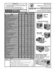
IMPORTANT<br />
1. Always include complete heater model and serial number so that<br />
any specification change can be considered for parts shipment. It<br />
can save time and expense.<br />
2. Specifications are subject to change without notice.<br />
3. We reserve the right to substitute functional replacements.<br />
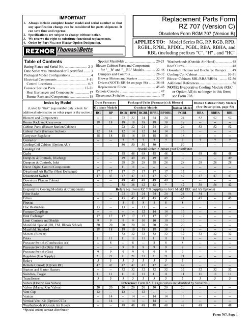
Replacement Parts Form<br />
RZ 707 (Version C)<br />
Obsoletes Form RGM 707 (Version B)<br />
4. Order by Part No.; not Heater Option Designation. APPLIES TO: Model Series RG, RP, RGB, RPB,<br />
RGBL, RPBL, RPDBL, PGBL, RBA, RBHA, and<br />
RBL (including prefixes "C", "H" , and "HC"<br />
Table of Contents<br />
Special Manifolds .................................. 20-21 Weatherhoods (Outside Air Hood) .................. 48<br />
Rating Plates and Serial No. ......................... 2-3 Blower Cabinet Parts and Components Roof Curbs ...................................................... 48<br />
Date Series was Introduced or Recertified ....... 3 for "__B" and "__BL" Models ............ 22-46 Downturn Plenum and Discharge Damper ...... 49<br />
Packaged Model Configurations ....................... 4 Dampers and Controls ............................ 28-32 Cooling Coil Cabinet ................................ 50-51<br />
Electrical Components ................................. 5-11 Blower Motors and Starters ................... 32-37 Blower Cabinets RBL/RBA/RBHA ........ 52-56<br />
Control Locations ....................................... 6-7 Drives (NOTE: RBHA on page 56) ....... 38-44 Additional References ..................................... 56<br />
Furnace Section Parts ............................... 12-21 Replacement Filters ............................... 45-46 NOTE: Evaporative Cooling Module (REC<br />
Heat Exchanger and Components ................ 17 Remote Console .............................................. 47 or Option AS) is no longer in this form;<br />
Burner Rack and Components ..................... 18 Disconnect Switches ....................................... 47 see Form 708.<br />
Index by Model<br />
Duct Furnaces Packaged Units [Furnace(s) & Blower] Blower Cabinet O nly Models<br />
(Listed by "first" page number only; check for Outdoor Models<br />
Outdoor Models<br />
Indoor Model (See Description, page 52)<br />
additional information on other pages in the section.) RG RP RGB RPB RGBL RPBL RPDBL PGBL RBA RBHA RBL<br />
Blowers and Components -- -- 22 22 24 24 24 24 52 52 52<br />
Burner Rack and Carryovers 18 18 18 18 18 18 18 18 -- -- --<br />
Cabinet Parts (Blower Section/Cabinet) -- -- 22 22 24 24 24 24 52 52 52<br />
Cabinet Parts (Furnace Section) 12 14 12 14 12 14 14 16 -- -- --<br />
Carryover Regulator 18 18 18 18 18 18 18 18 -- -- --<br />
Contactor -- -- 7 7 7 7 7 7 7 7 7<br />
Cooling Coil Cabinet (Option AU) -- -- 50 50 50 50 -- 50 -- -- --<br />
Cooling Coil<br />
Special Order - Contact your Distributor.<br />
Curbs -- -- 48 48 48 48 48 -- 48 48 48<br />
Dampers & Controls, Discharge -- -- 49 49 49 49 49 -- -- -- 49<br />
Dampers & Controls, Inlet -- -- 28 28 28 28 28 28 28 28 28<br />
Direct Digital Control Components -- -- 11 11 -- -- -- -- -- -- --<br />
Directional Air Baffles (Heat Exchanger) 17 17 17 17 17 17 17 17 -- -- --<br />
Disconnect Switch 47 47 47 47 47 47 47 47 47 47 47<br />
Downturn Plenum Cabinet -- -- 49 49 49 49 49 -- -- -- --<br />
Drives -- -- 38 38 42 42 * 42 38 56 42<br />
Evaporative Cooling Modules & Components<br />
Reference: Form RZ 708 (Applies to both Model REC and AS Options)<br />
Filter Racks -- -- 23 23 24 24 24 24 54 -- 54<br />
Filters -- -- 45 45 45 45 45 45 45 -- 45<br />
Firestat -- -- 8 8 8 8 8 8 -- -- --<br />
Flue Restrictors 13 -- 13 -- 13 -- -- -- -- -- --<br />
Furnace Couplings -- -- -- -- 12 14 14 16 -- -- --<br />
Heat Exchanger 17 17 17 17 17 17 17 17 -- -- --<br />
Limit Controls and Shields 9 9 9 9 10 10 10 10 -- -- --<br />
Manifold, Special (IRI, FM, Illinois School) 20 20 20 20 20 20 20 20 -- -- --<br />
Manifold, Standard 18 18 18 18 18 18 18 18 -- -- --<br />
Motors (Blower) -- -- 32 32 32 32 32 32 32 32 32<br />
Pilots 11 11 11 11 11 11 11 11 -- -- --<br />
Pressure Switch (Combustion Air) -- 8 -- 8 -- 8 8 8 -- -- --<br />
Pressure Switch (Dirty Filter) -- -- 9 9 9 9 9 9 -- -- --<br />
Pressure Switch (Gas) 9 9 9 9 9 9 9 9 -- -- --<br />
Regulator (Gas Supply) 21 21 21 21 21 21 21 21 -- -- --<br />
Relays 5 5 5 5 5 5 5 5 -- -- --<br />
Remote Console (Option RC) 47 47 47 47 47 47 47 47 -- -- --<br />
Starters and Starter Heaters -- -- 32 32 32 32 32 32 32 32 32<br />
Switches, Toggle 11 11 11 11 11 11 11 11 11 11 11<br />
Transformer 5 5 5 5 5 5 5 5 5 5 5<br />
Valves (Electric Gas Valves)<br />
Reference: Form RZ 714 (gas valves are identified by Serial No.)<br />
Valves (M anual Gas Valves) 20 20 20 20 20 20 20 20 -- -- --<br />
Vent Cap 12 -- 12 -- 12 -- -- -- -- -- --<br />
Venters -- 14 -- 14 -- 14 14 16 -- -- --<br />
Vertical Vent Kit (Option CC3) -- 14 -- 14 -- 14 -- -- -- -- --<br />
Weatherhoods (Outside Air Hood)<br />
*Special order; contact distributor.<br />
-- -- 48 48 48 48 48 48 48 -- 48<br />
Form 707, Page 1
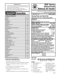
Duct Furnace Rating Plate<br />
REZNOR<br />
MERCER, PA. USA 16137<br />
DUCT FURNACE<br />
CATEGORY I<br />
FOR INDUSTRIAL/COMMERCIAL USE ONLY<br />
ANSI Z83.8 [ AA ] - [ A ] CGA 2.6 [ AA' ] -M [ A' ] DUCT FURNACE<br />
MODEL [ B ] [ C ]<br />
SERIAL NO. [ D ]<br />
[ E ] VOLTS [ E ] PH [ E ] HZ MAXIMUM TOTAL INPUT [ E ] AMPS<br />
TYPE OF GAS: [ F ] [ G ]<br />
ORIFICE SIZE [ J ] DRILL HAS BEEN FACTORY ADJUSTED<br />
FOR USE AT [ H ] FEET [ I ] METERS OF ALTITUDE.<br />
SEA LEVEL ALT. ADJUSTED<br />
NORMAL INPUT [ R ] [ K ]BTU/HR.<br />
OUTPUT CAPACITY [ S ] [ L ]BTU/HR.<br />
MINIMUM INPUT(2,M,MB,MV MODELS) [ T ] [ M ]BTU/HR.<br />
NORMAL MANIFOLD PRESSURE [ N ] IN.W.C.<br />
MIN. PERMISSIBLE GAS SUPPLY PRESSURE<br />
FOR PURPOSE OF INPUT ADJUSTMENT. [ O ] IN.W.C.<br />
MAXIMUM THROUGHPUT [ P ] C.F.M.<br />
MINIMUM THROUGHPUT [ Q ] C.F.M.<br />
CLEARANCES TO COMBUSTIBLE CONSTRUCTION: VENT CAP-10' , BOTTOM- 3",<br />
FLUE CONNECTION-6", SERVICE SIDE- WIDTH OF UNIT, OPPOSITE SIDE-6"<br />
THIS UNIT SHALL BE INSTALLED ON THE POSITIVE PRESSURE SIDE OF THE<br />
AIR CIRCULATING BLOWER.<br />
THIS UNIT MAY BE INSTALLED DOWNSTREAM FROM A REFRIGERATION<br />
SYSTEM (USE DRAIN OPTION CS1).<br />
THIS UNIT MAY BE USED WITH DUCTS.<br />
THIS UNIT IS FOR OUTDOOR INSTALLATION ONLY.<br />
MINIMUM OPERATIONAL AMBIENT AIR TEMPERATURE: -40 DEG. F<br />
THIS UNIT IS FOR USE WITH NATURAL GAS AND PROPANE. A<br />
CONVERSION KIT AS SUPPLIED BY THE MANUFACTURER, SHALL BE<br />
USED TO CONVERT THIS DUCT FURNACE TO THE ALTERNATE FUEL.<br />
FOR ALTERNATE INSTALLATIONS USE THE LATEST EDITIONS OF THE<br />
APPROPRIATE STANDARD LISTED BELOW:<br />
FOR AIRCRAFT HANGERS USE STANDARD ANSI/NFPA 409<br />
FOR PARKING STRUCTURES USE STANDARD ANSI/NFPA 88A<br />
FOR REPAIR GARAGES USE STANDARD ANSI/NFPA 88B<br />
Blower Cabinet Rating Plate on Certified Packaged Units (see table on page 3)<br />
Key to Cabinet Rating Plate<br />
REZNOR<br />
MERCER, PA., U.S.A. 16137<br />
PACKAGED DUCT FURNACE<br />
FOR INDUSTRIAL/COMMERCIAL USE ONLY<br />
DESIGN CERTIFIED FOR A.G.A REQUIREMENTS UNDER<br />
[ A ] PACKAGED DUCT FURNACE STANDARD<br />
MODEL [ B ] [ C ]<br />
SERIAL NO. [ D ] HP<br />
[ E ] VOLTS [ E ] PH [ E ] HZ MAXIMUM TOTAL INPUT [ E ] AMPS<br />
IF EQUIPPED WITH R.E.C. OPTION, ADD [ V ] AMPS<br />
EQUIPPED FOR OPERATION AT AN AIR FLOW OF [ F ] SCFM<br />
AGAINST A STATIC PRESSURE OF [ G ] INCHES WATER COLUMN.<br />
DRIVE NO. [ H ] WIRING DIAGRAM [ I ]<br />
SEE MANUFACTURER'S INSTRUCTIONS FOR OTHER AIR FLOW<br />
CAPACITIES.<br />
FILTERS, WHEN USED, MUST BE INSTALLED EXTERNAL TO THE<br />
HEATING CASING.<br />
REFER TO THE RATING PLATE OF THE DUCT FURNACE FOR<br />
ADDITIONAL INFORMATION.<br />
Form 707, Page 2<br />
A = Standard<br />
B = Model<br />
C = Date of Manufacture<br />
Key to Duct Furnace Rating Plate<br />
A = Standard<br />
B = Model and Size<br />
C = Date of Manufacturer<br />
D = Serial No.<br />
E = Volts/PH/Hz/Amps<br />
F & G = Natural or Propane Gas<br />
H & I = Altitude<br />
J = Orifice Drill Size<br />
K = Normal Input (altitude<br />
adjusted)<br />
L = Thermal Output (altitude<br />
adjusted)<br />
De-Coding a Serial No.<br />
Sample: S AZJ 66 K1 N 12345 MV3<br />
1 | 2 | 3 | 4 | 5 | 6 | 7<br />
1 = Stainless steel heat exchanger (with an aluminized heat<br />
exchanger, there is no letter suffix<br />
2 = Date code (see page 3)<br />
3 = Pilot code (Reference Form RZ 714)<br />
4 = Valve code (Reference Form RZ 714)<br />
5 = N is natural gas; L is propane gas<br />
6 = Consecutive number<br />
7 = Maxitrol system (optional)<br />
D = Motor Horsepower<br />
E = Volts/Phase/Hertz/Amps<br />
F = SCFM<br />
M = Minimum Input (altitude<br />
adjusted)<br />
N = Normal Manifold Pressure<br />
O = Minimum Gas Supply<br />
Pressure<br />
P = Maximum Air Throughput<br />
Q = Minimum Air Throughput<br />
R = Normal Input (sea level)<br />
S = Thermal Output (sea level)<br />
T = Minimum Input (sea level)<br />
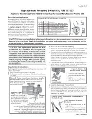
Replacement Parts Tag - Each unit has a replacement parts tag<br />
that includes the Model No. and the Serial No. as well as a list of<br />
original common replacement parts. Always provide the full model<br />
and serial numbers when ordering replacement parts.<br />
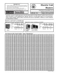
Identification Plate on Blower Cabinets Manufactured Prior to<br />
Package Certification (see dates on page 3)<br />
HP Codes<br />
MODEL NUMBER SERIAL NUMBER<br />
DRIVE NO. WIRING DIAGRAM NO.<br />
CFM _____ AT____ IN. W.C. MAX. E.S.P. AND ____ HP<br />
VOLTS PHASE HERTZ AMPERES<br />
Single-Speed Motors 2-Speed Motors<br />
Code HP Code HP<br />
05 1 20 1/.44<br />
06 1-1/2 21 1.5/.68<br />
07 2 22 2/.88<br />
08 3 23 3/1.3<br />
09 5 24 5/2.2<br />
11 7-1/2 25 7.5/3.3<br />
12 15 26 10/4.4<br />
13 10<br />
14 20<br />
G = Static Pressure (w.c.)<br />
H = Drive AM Option Code<br />
I = Wiring Diagram No.
First Element of the Serial Number - Date of Manufacture<br />
Year Jan Feb Mar Apr May June July Aug Sept Oct Nov Dec<br />
1989 AOA AOB AOC AOD AOE AOF AOG AOH AOI AOJ AOK AOL<br />
1990 APA APB APC APD APE APF APG APH API APJ APK APL<br />
1991 AQA AQB AQC AQD AQE AQF AQG AQH AQI AQJ AQK AQL<br />
1992 ARA ARB ARC ARD ARE ARF ARG ARH ARI ARJ ARK ARL<br />
1993 ASA ASB ASC ASD ASE ASF ASG ASH ASI ASJ ASK ASL<br />
1994 ATA ATB ATC ATD ATE ATF ATG ATH ATI ATJ ATK ATL<br />
1995 AUA AUB AUC AUD AUE AUF AUG AUH AUI AUJ AUK AUL<br />
1996 AVA AVB AVC AVD AVE AVF AVG AVH AVI AVJ AVK AVL<br />
1997 AWA AWB AWC AWD AWE AWF AWG AWH AWI AWJ AWK AWL<br />
1998 AXA AXB AXC AXD AXE AXF AXG AXH AXI AXJ AXK AXL<br />
1999 AYA AYB AYC AYD AYE AYF AYG AYH AYI AYJ AYK AYL<br />
2000 AZA AZB AZC AZD AZE AZF AZG AZH AZI AZJ AZK AZL<br />
2001 BAA BAB BAC BAD BAE BAF BAG BAH BAI BAJ BAK BAL<br />
2002 BBA BBB BBC BBD BBE BBF BBG BBH BBI BBJ BBK BBL<br />
2003 BCA BCB BCC BCD BCE BCF BCG BCH BCI BCJ BCK BCL<br />
2004 BDA BDB` BDC BDD BDE BDF BDG BDH BDI BDJ BDK BDL<br />
2005 BEA BEB BEC BED BEE BEF BEG BEH BEI BEJ BEK BEL<br />
2006 BFA BFB BFC BFD BFE BFF BFG BFH BFI BFJ BFK BFL<br />
2007 BGA BGB BGC BGD BGE BGF BGG BGH BGI BGJ BGK BGL<br />
2008 BHA BHB BHC BHD BHE BHF BHG BHH BHI BHJ BHK BHL<br />
2009 BIA BIB BIC BID BIE BIF BIG BIH BII BIJ BIK BIL<br />
2010 BJA BJB BJC BJD BJE BJF BJG BJH BJI BJJ BJK BJL<br />
2011 BKA BKB BKC BKD BKE BKF BKG BKH BKI BKJ BKK BKL<br />
2012 BLA BLB BLC BLD BLE BLF BLG BLH BLI BLJ BLK BLL<br />
2013 BMA BMB BMC BMD BME BMF BMG BMH BMI BMJ BMK BML<br />
2014 BNA BNB BNC BND BNE BNF BNG BNH BNI BNJ BNK BNL<br />
2015 BOA BOB BOC BOD BOE BOF BOG BOH BOI BOJ BOK BOL<br />
2016 BPA BPB BPC BPD BPE BPF BPG BPH BPI BPJ BPK BPL<br />
2017 BQA BQB BQC BQD BQE BQF BQG BQH BQI BQJ BQK BQL<br />
2018 BRA BRB BRC BRD BRE BRF BRG BRH BRI BRJ BRK BRL<br />
2019 BSA BSB BSC BSD BSE BSF BSG BSH BSI BSJ BSK BSL<br />
2020 BTA BTB BTC BTD BTE BTF BTG BTH BTI BTJ BTK BTL<br />
2021 BUA BUB BUC BUD BUE BUF BUG BUH BUI BUJ BUK BUL<br />
2022 BVA BVB BVC BVD BVE BVF BVG BVH BVI BVJ BVK BVL<br />
2023 BWA BWB BWC BWD BWE BWF BWG BWH BWI BWJ BWK BWL<br />
2024 BXA BXB BXC BXD BXE BXF BXG BXH BXI BXJ BXK BXL<br />
2025 BYA BYB BYC BYD BYE BYF BYG BYH BYI BYJ BYK BYL<br />
2026 BZA BZB BZC BZD BZE BZF BZG BZH BZI BZJ BZK BZL<br />
Date Series was Introduced or<br />
Recertified (may affect parts selection)<br />
Duct Furnace Certification<br />
Model Agency<br />
Recertified<br />
Introduced Series<br />
(H)(C)(HC) RP A.G.A. 2/90 --<br />
(H) RP A.G.A. -- Series 8 - 5/95<br />
(H)(C)(HC) RG A.G.A. 2/90 Series 8 - 5/95<br />
(H) RG C.G.A. 5/90 Series 8 - 5/95<br />
(H) RP C.G.A. 5/90 Series 8 - 5/95<br />
Packaged Unit Certification<br />
Model Agency Certified<br />
(H)(C)(HC) RGB A.G.A. 2/96<br />
(H) RPB A.G.A. 2/96<br />
RPBL, (C)RGBL A.G.A. 11/96<br />
PGBL A.G.A. 3/97<br />
(H)(C)(HC) RGB C.G.A. 8/96<br />
(H) RPB C.G.A. 8/96<br />
RPBL, (C)RGBL C.G.A. 8/97<br />
PGBL C.G.A. 8/97<br />
Beginning January 2000, heaters display a CSA label certifying<br />
that the unit or system has been approved to ANSI<br />
Standards for use in the United States or to C.G.A. Standards<br />
for use in Canada.<br />
Descriptions of Currently Manufactured Models (Prefix "H"<br />
indicates higher CFM capacity; "C" indicates higher thermal efficiency;<br />
"HC" indicates higher CFM capacity and thermal efficiency)<br />
Model No.<br />
Series of Type Capacity Ranges Vent Installation<br />
Sizes<br />
Thermal<br />
Efficiency<br />
PGBL 3 Packaged 400-1200 MBH Input/ 80% Power Indoor<br />
System 3300-13500 CFM only<br />
RG 11 Duct Furnace 75-400 MBH Input 78% Gravity Outdoor<br />
RGB 11 Packaged 75-400 MBH Input/ 78% Gravity Outdoor<br />
System 600-7100 CFM<br />
RGB 11 Packaged 75-400 MBH Input/ 78% Gravity Outdoor<br />
System 600-7100 CFM<br />
RGBL 7 Packaged 400-1200 MBH Input/ 78% Gravity Outdoor<br />
System 3300-13500 CFM<br />
RP 9 Duct Furnace 125-400 MBH Input 80% Power Outdoor<br />
RPB 9 Packaged 125-400 MBH Input/ 80% Power Outdoor<br />
System 1025-7100 CFM<br />
RPBL 7 Packaged 400-1200 MBH Input/ 80% Power Outdoor<br />
System 3300-13500 CFM<br />
RPDBL 5 Packaged 800-1600 MBH Input/ 80% Power Outdoor<br />
System 6600-22000 CFM<br />
RBA 1 Blower only 1500-5000 CFM -- -- Indoor/Outdoor<br />
RBHA 1 Blower only 1500-5000 CFM -- -- Indoor/Outdoor<br />
RBL 1 Blower only 5000-15000 CFM -- -- Indoor/Outdoor<br />
Form 707, Page 3
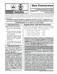
Packaged Models - Blower/Furnace Configurations<br />
Outdoor (H)(C)RGB and (H)RPB Systems<br />
1. Model RG, CRG, HRG, HCRG, RP, or HRP duct furnace coupled together with a<br />
"B" Blower Cabinet.<br />
2. Optional outside air hood, downturn plenum, coil cabinet (with or without downturn),<br />
and evaporative cooling module may be part of the packaged unit.<br />
Outdoor (C)RGBL and RPBL Systems<br />
1. Model HRG, HCRG, or HRP duct furnaces (in quantity and size<br />
indicated below) coupled together with a "BL" Blower Cabinet.<br />
2. Optional outside air hood, downturn plenum, coil cabinet (with<br />
or without downturn), and evaporative cooling module may be<br />
part of the packaged unit.<br />
Unit Direction Orientation Diagram -<br />
Model RPBL 500 illustrated<br />
NOTE: Left side controls (illustrated)<br />
are standard. Right side controls are<br />
optional. If the unit has right side<br />
controls, some replacement parts will<br />
be affected.<br />
Form 707, Page 4<br />
"BL"<br />
Cabinet<br />
Duct<br />
Furnace<br />
"BL"<br />
Cabinet<br />
Duct<br />
Furnace<br />
Duct<br />
Furnace<br />
"BL"<br />
Cabinet<br />
Duct<br />
Furnace<br />
Duct<br />
Furnace<br />
Duct<br />
Furnace<br />
End<br />
Left<br />
Right<br />
Front<br />
"B"<br />
Cabinet<br />
Duct<br />
Furnace<br />
Indoor PGBL System<br />
1. A PGBL packaged system is a duct furnace (in quantity and size<br />
indicated below) coupled together with a "BL" Blower Cabinet.<br />
2. Optional downturn plenum, coil cabinet (with or without downturn),<br />
and evaporative cooling module may be part of the packaged<br />
unit.<br />
Packaged Includes One Size 400 Duct Furnace<br />
Model Series Size 250 300 350 400<br />
RGBL/RPBL/PGBL 400 -- -- -- 1<br />
Packaged Includes Size & Quantity of Furnaces<br />
Model Series Size 250 300 350 400<br />
RGBL/RPBL 500 2 -- -- --<br />
RGBL/RPBL 600 -- 2 -- --<br />
RGBL/RPBL 700 -- -- 2 --<br />
RGBL/RPBL/PGBL 800 -- -- -- 2<br />
Packaged Includes Size & Quantity of Furnaces<br />
Model Series Size 250 300 350 400<br />
RGBL/RPBL 1050 -- -- 3 --<br />
RGBL/RPBL/PGBL 1200 -- -- -- 3<br />
Outdoor RPDBL Systems<br />
1. HRP duct furnaces (in quantity and size indicated below) coupled together with two "BL" Blower Cabinets.<br />
2. Optional outside air hoods and downturn plenum cabinets may be part of the packaged unit.<br />
NOTE: Replacement parts are not identified for these specific models; look for equivalent RPBL models.<br />
Size 800<br />
"BL"<br />
Cabinets<br />
Duct<br />
Furnaces<br />
Sizes 1000/1200/1400/1600<br />
"BL"<br />
Cabinets<br />
Duct<br />
Furnaces<br />
RPDBL Consists of:<br />
800 (2) RPBL 400 Packaged Systems<br />
1000 (2) RPBL 500 Packaged Systems<br />
1200 (2) RPBL 600 Packaged Systems<br />
1400 (2) RPBL 700 Packaged Systems<br />
1600 (2) RPBL 800 Packaged Systems
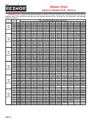
Line Voltage Application to Package Configuration<br />
Line Voltage to Furnace or Packaged System<br />
Unit Voltage 115 208 230 460 575 Comments<br />
RG Control Volts In/Out/VA 115/24/20 208/24/20 230/24/20 460/24/20 N/A Furnace only<br />
RGB Motor Voltage 115 208 230 460 575<br />
RGB Controls Volts In/Out/VA 115/24/40 208/24/40 230/24/40 460/24/40 575/24/200<br />
RP Control Volts In/Out/VA 115/24/40 208/24/40 230/24/40 460/24/40 N/A Furnace only<br />
RPB Motor Voltage 115 208 230 460 575<br />
RPB Controls Volts In/Out/VA 115/24/40 208/24/40 230/24/40 460/24/40 115/24/40 575 to 115V / 300VA Transformer<br />
RPBL/RGBL/PGBL 400 115 208 230 460 115 575 to 115V / 300VA Transformer<br />
RPBL/RGBL 500-800; PGBL 800 115 208 230 460 115 575 to 115V / 500VA Transformer<br />
RPBL/RGBL 1050-1200; PGBL 1200 115 208 230 460 115 575 to 115V / 750VA Transformer<br />
Quick Reference Charts (Note: Consult wiring diagram to verify relays and transformers.)<br />
Relay Chart Relay P/N<br />
Where Used 103317 98118 110656 46233<br />
Freezestat Relay X<br />
Starter Relay X<br />
Summer/Winter Relay (Option BF2) X<br />
SPST Relay, Option BG2 X<br />
SPDT Relay, Option BG3 X<br />
SPST Relays, Option BG4 X(2)<br />
SPST and SPDT Relay, Option BG5 X X<br />
Illinois School Code Controls (Option BM12) X X<br />
Two-Speed Motor Relay X<br />
Two-Speed Motor Speed Relay X<br />
IRI Gas Controls (Option BM13) X(4)<br />
Discharge Damper X(2)<br />
Time Delay Relay Venter (RP Series & PGBL) X<br />
Blower Relay X<br />
DDC Interface Relay (Options D1, 2, 3, 4) X (2or3)<br />
Gas Control Option AG39 or AG40 X<br />
Transformer Chart<br />
P/N<br />
Transformer Volts<br />
RG Controls<br />
RP Controls<br />
RGB(L) Controls<br />
RPB(L)Controls<br />
PGBL Controls<br />
RBHA/RBA/RBL<br />
Controls<br />
In Out VA<br />
103054 115 24 20 X<br />
103055 115 24 40 X X X X X X<br />
103497 208-230 24 40 X X X<br />
103498 480 24 40 X X X<br />
38634 115 24 200 X<br />
39094 208 24 200 X X X X<br />
39095 230-460-575 24 200 X X X X<br />
86991 208 115 250 X X X<br />
105202 230-460-575 115 300 X X X X X X<br />
86985 230-460 115 300 X X<br />
86998 208 115 500 X<br />
86997 230-460 115 500 X<br />
112641 575 115 500 X<br />
112642 575 115 750 X<br />
575V Line<br />
RPBL/PGBL400<br />
575V Line RPBL400-<br />
800; PGBL 800/1200<br />
575V Line RPBL<br />
1050-1200<br />
IRI Manifold<br />
FM Manifold<br />
Convenience Outlet<br />
Used in Option D1-4<br />
(DDC from<br />
building's environmental<br />
control<br />
system)<br />
Discharge Damper<br />
Form 707, Page 5
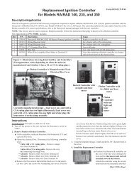
Furnace Electrical Component Locations<br />
("B" Cabinet is illustrated; control locations<br />
are the same in the larger capacity "BL"<br />
Cabinets)<br />
NOTE: See pages 8 - 10 for illustrations and additional information<br />
about the furnace electrical components listed below.<br />
Code Description P/N<br />
1A Electrical Box 100108<br />
1B Electrical Box Cover 100109<br />
2 Freezestat, Auto Reset (Option BE2) 126170<br />
3A Combustion Air Pressure Switch (RP Series) 125133<br />
- Replacement part depends on the date of<br />
manufacture and original equipment; see<br />
page 8 before selecting replacement switch.<br />
3B Combustion Air Pressure Switch (PGBL) 125133<br />
4 Discharge Air Firestat (Option BD2) 42782<br />
5A Ignition Controller (Recycle G67BG-5) 97782<br />
5B Ignition Controller (Lockout G770NGC-4) 97547<br />
6 Discharge Air Sensor (modulating gas cntrls) 48041<br />
7A 2-Stage Controller (for Option AG3) 41700<br />
7B 2-Stage Ductstat Sensor Holder (AG15-20) 115850<br />
7C Remote Ductstat Modules (AG15-20) - see page 8<br />
8 Main Low Gas Pressure Switch (Opt BP3) See<br />
9 Pilot Low Gas Pressure Switch (Opt BP3) page 9<br />
10 Main High Gas Pressure Switch (Opt BP2) 93850<br />
11 Gas Pressure Switches in Opt AG39 & 40 - see page 9<br />
12 Time Delay Relay (RP Series) 46233<br />
13A Limit Control RG(B) & RP(B) only 50417<br />
(for BL systems, see page 10)<br />
13B Limit Shield RG(B) & RP(B) only 12229<br />
14 Fan Control RGB(L), RPB(L), PGBL 10357<br />
15 Freezestat Time Delay Relay 89661<br />
16 Line Voltage Terminal Blocks 144972<br />
17 Line Voltage Terminal Block Adapter 144973<br />
18 Heat Shield ANSI (used in U.S.) 10188<br />
C.G.A. (used in Canada) 63818<br />
19 Low Voltage Terminal Blocks (See Code 16) 144972<br />
Form 707, Page 6<br />
Venter assembly and combustion<br />
air switch on indoor Model PGBL<br />
is on top of the unit.<br />
3B<br />
Optional Downturn<br />
Plenum Cabinet<br />
Maxitrol Amplifier<br />
(See Form RZ-714)<br />
*Code 3A - Beginning with units manufactured 2/99, the pressure<br />
switch on RP Series units is mounted inside the electrical box. Prior<br />
to 2/99, the pressure switch is mounted on the wall of the electrical<br />
compartment above the electrical box. See page 8 for replacement<br />
information.<br />
Code Description P/N<br />
20 Low Voltage Terminal Block Adapter 144973<br />
21 Freezestat Relay 103317<br />
22 Dirty Filter Pressure Switch 105507
Blower Cabinet Electrical Component Location ("B" Cabinet is illustrated; control locations are<br />
the same in the larger capacity "BL" Cabinets)<br />
See Note at the bottom<br />
of the page about<br />
building management<br />
control option.<br />
Reference NOTE: Except where a page number is listed, see pages 8 - 10<br />
for illustrations and additional information about the blower cabinet electrical<br />
components.<br />
Building Management Control NOTE: If equipped with Option D1-4<br />
for DDC interface to the building's computerized environmental control<br />
system, the dotted line indicates the location of the electrical box that<br />
houses the specially programmed Johnson Control Metasys ® control unit.<br />
Box Cover is P/N 171739. Other components are listed on page 11.<br />
Optional Downturn<br />
Plenum Cabinet<br />
Code Description P/N<br />
25 Fuse Holder (Fuse, see page 9) 38635<br />
26 Convenience Outlet (all voltages) 96912<br />
27 Convenience 208 to 115, 200VA 86991<br />
Outlet 230/460 to 115, 300VA 86985<br />
Transformer 575 to 115, 300VA 105202<br />
28A Blower Motor Contactor - 24V Coil 119625<br />
(replaces P/N 93661)<br />
28B Blower Motor Starters - see pages 30 - 35<br />
29 High Ambient Limit Control (Opt BN2) 126170<br />
30 Outside Air or Return Air Controller 126170<br />
31 Mixed Air Controller 16109<br />
32 Potentiometer 16110<br />
33 Starter Relay (replaces 105803) 110656<br />
34 Summer Winter Relay (Option BF2) 98118<br />
35 RBM Relay (Option BG2, BG4) 98118<br />
36 RBM Relay (Option BG3, BG5) 103317<br />
37 2-Speed Motor Speed Selector 110656<br />
38 Auto Reset Reverse Flow Limit 103323<br />
39 Return Air Firestat (Option BD3); See Code 4 42782<br />
40 Low Voltage Terminal Blocks 144972<br />
41 Low Voltage Terminal Block Adapters 144973<br />
42A Control 115V to 24V, 20VA 103054<br />
and and 115 to 24V, 40VA 103055<br />
42B Damper 208/230 to 24V, 40VA 103497<br />
Transformers 460 to 24V, 40VA 103498<br />
(See 208 to 24V, 200VA 39094<br />
Chart on 230/460/575 to 24V, 200VA 39095<br />
page 5) 230/460 to 115V, 300VA 86985<br />
230/460/575 to 115V, 300VA 105202<br />
208 to 115V, 500VA 86998<br />
230/460 to 115V, 500VA 86997<br />
575 to 115V, 500VA 112641<br />
575 to 115V, 750VA 112642<br />
43 Air Proving Switch 112107<br />
44A Blower Cabinet Electrical Box - std left side controls 100092<br />
Blwr Cbnt Elctrcl Box - optional right side controls 95486<br />
44B Electrical Box Cover 100095<br />
Form 707, Page 7
Electrical Components - See location drawings on pages 6-7.<br />
Code 1 - Electrical Box<br />
and Cover (in the<br />
electrical compartment)<br />
Electrical Box, P/N 100108<br />
(replaces 11965 on<br />
Model RG)<br />
Electrical Box<br />
Cover, P/N 100109<br />
(replaces P/N 9546 on<br />
Model RG)<br />
Code 3B - Combustion<br />
Air Switch used on "RP"<br />
Models with Option<br />
AG39 or AG40, Tridelta<br />
FS6788-3007, P/N 175863<br />
or Tridelta FS6788-3006,<br />
P/N 175862<br />
Code 6, Discharge Sensor<br />
for Modulating Gas Valve,<br />
Maxitrol TS-121,<br />
P/N 48041<br />
Gasket,<br />
P/N 104138<br />
Code 7A, Two-Stage<br />
Ductstat, Honeywell<br />
T678A1015,<br />
P/N 41700<br />
55-58°F,<br />
Capillary Length 5' - Used<br />
in Gas Control Options<br />
AG3, AG4, and AG5<br />
Form 707, Page 8<br />
Code 2 - Freezestat, J/C<br />
#AI9AAF-12C, 25-225 o F, P/N<br />
126170, (replaces P/N 16108)<br />
Grommet Clamp,<br />
P/N 131993<br />
Cable Clamp,<br />
P/N 132065<br />
Bulb Clamp,<br />
P/N 100260<br />
Code 3C - PGBL Series<br />
Combustion Air Switch,<br />
Tridelta Tridelta FS6788-<br />
1621setpoint 0.58 ± .05"<br />
w.c., P/N 125133<br />
For altitudes above 4000 ft,<br />
order P/N 125134<br />
(Setpoint 0.52 ± .05" w.c.)<br />
Location and Components for<br />
Installing Discharge Sensor in<br />
Code 7A<br />
Sheetmetal<br />
Retaining Plate,<br />
P/N 7727<br />
Ductwork<br />
Gasket,<br />
P/N 7726<br />
Capillary<br />
Element Bracket<br />
P/N 104156<br />
Cabinet<br />
Leg<br />
Code 3A - RP Series Combustion Air Switch<br />
P/N 68266, Tridelta<br />
FS4100-4871setpoint<br />
0.58 ± .05" w.c., order<br />
when switch is on the wall<br />
above the<br />
electrical<br />
box<br />
For<br />
altitudes<br />
above 4000 ft,<br />
order P/N 113234<br />
(Setpoint 0.52 ± .04" w.c.)<br />
If replacing P/N 68266 with P/N 125133, it is necessary to re-locate<br />
the pressure switch. Order sensing tube, P/N 171750, for the venter<br />
assembly and sensing tube, P/N 133117, to connect to the switch. Mount<br />
switch inside the electrical box; plug holes in wall with screws.<br />
RP Models manufactured prior to 12/91 (Serial No. Date Code AQL)<br />
order Replacement Pressure Switch Kit, P/N 93033<br />
Codes 4 & 39 - Firestat,<br />
Honeywell #L4029E<br />
1029, Manual reset opens<br />
at 200 o F, P/N 42782<br />
Firestat<br />
Gasket,<br />
P/N<br />
121041<br />
(used when<br />
firestat is<br />
installed<br />
less cover)<br />
Firestat Shield, P/N<br />
120021 (used with<br />
discharge firestat only)<br />
Code 7B,<br />
Ductstat Sensor<br />
and Holder for<br />
Code 7C Remote<br />
Ductstats<br />
Code 5A -<br />
Recycling<br />
Ignition<br />
Controller,<br />
J/C G67BG-5,<br />
P/N 97782<br />
Code 5B -<br />
Ignition<br />
Controller with<br />
lockout (120<br />
second timing),<br />
J/C G770NGC-<br />
4, P/N 97547<br />
Ductstat Sensor only,<br />
#SET A99BC-25C, P/N 115851,<br />
(part of P/N 115848 below)<br />
Code 7C - Remote<br />
Ductstat Modules<br />
Used in Gas<br />
Control<br />
Options<br />
AG15-AG20<br />
P/N 125133, Tridelta FS6788-<br />
1621setpoint 0.58 ± .05" w.c.,<br />
order when switch is mounted<br />
inside the electrical box<br />
For<br />
altitudes<br />
above 4000 ft,<br />
order P/N 125134<br />
(Setpoint 0.52 ± .05" w.c.)<br />
Ductstat Sensor Holder,<br />
#TE6001-1, P/N 115850<br />
A B C<br />
A = Ductstat Temperature Selector Module, J/C A350AA-<br />
1C, P/N 115848<br />
B = Stage Adder Module, J/C S350AA-1C, P/N 115849<br />
C = Digital Temperature Display Module, J/C D350AA-<br />
1C, P/N 115852
Codes 8, 9, 10 - Gas Pressure Switches<br />
Codes 8 & 9 - Low Gas<br />
Pressure Switch,<br />
P/N 93849 (Range 1-6" w.c.);<br />
P/N 149176 (Range 6-24" w.c.)<br />
Automatic Reset, Settings - 50%<br />
of minimum inlet gas pressure as<br />
stated on the unit rating plate<br />
Code 10 - High Gas<br />
Pressure Switch,<br />
P/N 93850, Manual<br />
Reset, Settings - 125%<br />
of normal manifold gas<br />
pressure as stated on<br />
the unit rating plate<br />
Vent Limiter, Maxitrol<br />
A1209, P/N 123481<br />
Code 12 - Time Delay<br />
Relay, TI 60000GO-<br />
17, P/N 46233<br />
20second<br />
delay<br />
Codes 16 & 17; 19 & 20;<br />
and 40 & 41<br />
Terminal<br />
Block, P/N<br />
144972<br />
Code 25 - Fuse and<br />
Fuseholder<br />
Terminal<br />
Block<br />
Adapter,<br />
P/N<br />
144973<br />
Fuse Holder, P/N 38635<br />
Fuses:<br />
2-1/2 Amp, P/N 61542<br />
5 Amp, P/N 90335<br />
8 Amp, P/N 38636<br />
Code 13A - Limit<br />
Control, P/N 50417,<br />
opens 125 o F; closes<br />
105 o F<br />
Used on RG, RGB,<br />
RP, RPB Series units;<br />
for "BL" packaged<br />
systems, see page 10.<br />
Bracket,<br />
P/N 100261<br />
Code 18 - Heat Shields<br />
For U.S.<br />
(approved<br />
to ANSI)<br />
Unit,<br />
P/N 10188<br />
Primary Gas<br />
Flow Pressure<br />
Switch<br />
White Label<br />
1.1” w.c.<br />
Code 13B - Limit<br />
Control Shield,<br />
P/N 12229<br />
Used with Code 13A<br />
on Models RG and<br />
RGB<br />
For Canada<br />
(approved to<br />
C.G.A.) Unit,<br />
P/N 63818<br />
Code 26 - Convenience Outlet<br />
Receptacle, P/N 96912<br />
Convenience Outlet Fuse,<br />
Bussman #MDQ 1-1/2, Dual<br />
Element, Time Delay,<br />
P/N 193803<br />
Fuseholder, P/N 38635<br />
Code 11 - Gas Pressure Switches used in Gas Control Options<br />
AG39 and AG40<br />
P/N 174809, primary<br />
switch set at 1.1" w.c.<br />
Carryover<br />
gu<br />
Regulator<br />
Backup Gas Flow<br />
Pressure Switch<br />
Yellow Label<br />
1.4” w.c.<br />
Modulating<br />
Valve<br />
Code 14 - Fan<br />
Control, P/N 10357<br />
Code 21 - Freezestat Relay,<br />
Products Unlimited #9400-<br />
04Q180, 24V Coil, P/N<br />
103317<br />
Code 27 - Convenience<br />
Outlet Transformer<br />
Volts<br />
P/N In Out VA<br />
86991 208 115 250<br />
86985 230-460 115 300<br />
105202 230-460-575 115 300<br />
P/N 175985, backup<br />
switch set at 1.4" w.c.<br />
Single-Stage<br />
Gas Valve<br />
Note: Carryover regulator parts are on page18. See Parts Form<br />
714 for gas valves.<br />
Code 15 - Time Delay<br />
Relay, T & B Agastat<br />
TM1ULA, P/N 89661<br />
Used in the freezestat<br />
circuit.<br />
Code 22 - Dirty Filter<br />
Pressure Switch, Tridelta<br />
AP4434, P/N 105507<br />
Field adjustable; range .17<br />
to 5.0" w.c. plus or minus<br />
.05" w.c.<br />
Code 28A - Motor<br />
Contactor (less case),<br />
Furnas 42AF35AJ, 24V<br />
Coil, P/N 119625<br />
(replaces P/N 93661)<br />
For blower motor starters,<br />
see pages 30-35.<br />
Form 707, Page 9
Electrical Components (cont'd) - See location drawings on pages 6-7.<br />
Codes 29 and 30<br />
- High Ambient<br />
Limit Control<br />
and Outside<br />
Air or<br />
Return<br />
Air<br />
Controller,<br />
P/N<br />
126170<br />
Code 36 - RBM Relay,<br />
Products Unlimited<br />
#9400-04Q180, 24V coil,<br />
P/N 103317<br />
Codes 42B - Control and<br />
Damper Transformers,<br />
200 and<br />
300 VA<br />
P/N 105202, 575/115/<br />
300VA - Use on 115V<br />
furnace<br />
P/N 39095, 230/460/575-<br />
24-200VA<br />
P/N 39094, 208/24/200VA<br />
Limit Controls used on Model Series<br />
RGBL, PGBL and RPBL mfgd<br />
beginning 1/97 (for older<br />
units, see below)<br />
Automatic Reset<br />
Limit Control<br />
with Linear<br />
Sensor, TOD<br />
#10HG11,<br />
P/N 148588<br />
Limit Controls and Shields used on<br />
Model Series RGBL and RPBL mfgd<br />
prior to 1/97<br />
Limit Shields<br />
P/N 12229 P/N 9704<br />
Form 707, Page 10<br />
Code 31 - Mixed<br />
Air Controller,<br />
P/N 16109<br />
Code 37 - 2-Speed Motor<br />
Speed Selector Relay, Essex<br />
91-102006-1300, 24V,<br />
P/N<br />
110656<br />
Codes 43 - Blower Air Flow<br />
Switch, Tridelta FP6605,<br />
Normally Open Non-<br />
Adjustable,<br />
Setpoint<br />
.175"w.c.,<br />
P/N<br />
112107<br />
(Air Proving Switch, Option<br />
BW1)<br />
See page 24 for blower<br />
pitot probe.<br />
Automatic<br />
Reset<br />
Limit<br />
Control,<br />
TOD<br />
#60T11<br />
Code 32 -<br />
Potentiometer,<br />
P/N 16110<br />
Bracket<br />
P/N 18795<br />
Code 33 - Blower Relay/<br />
2-Speed Motor Relay,<br />
Essex 91-<br />
102006-<br />
1300,<br />
24V,<br />
P/N<br />
110656<br />
(replaces<br />
105803<br />
Code 38 -<br />
Reverse Flow<br />
Limit, #60T11-<br />
313154,<br />
P/N 103323<br />
Codes 42A - Control and<br />
Damper Transformers,<br />
20 and 40 VA<br />
Codes 34 & 35 - RBM<br />
Relay, Essex 134-2012-<br />
101, 24V,<br />
P/N<br />
98118<br />
Code 39 - See Code 4, page 8.<br />
Codes 40 & 41 - See Codes 16 & 17, pg 9.<br />
P/N 103054, 115/24/20VA,<br />
Basler #BE121625-WAR<br />
P/N 103055, 115/24/40VA, Basler<br />
#BE141650-WAA<br />
P/N 103497, 208/230/24/40VA, Basler<br />
#BE2153900<br />
P/N 103498, 460/24/40VA, Basler<br />
#BE23975001<br />
Code 44 - Blower Cabinet Electrical Boxes and Covers<br />
Left Side Controls - Cover,<br />
P/N 100092; Box, P/N 100095<br />
Automatic Reset<br />
Limit Control,<br />
TOD #60T11<br />
"BL" Blower<br />
Cabinet<br />
Air<br />
Flow<br />
Optional Right Side<br />
Controls - Box, P/N 95486<br />
(See<br />
Orientation<br />
Illustration<br />
on page 4)<br />
Key: (Applies to both limit tables)<br />
Furnace<br />
#1<br />
Furnace<br />
#2<br />
Furnace<br />
#3<br />
Furnace Size 400 Sizes 500/600/800 Sizes 1050/1200<br />
#1 50418, -201220, 145 o F 50418, -201220, 145 o F 50417, -201234, 125 o F<br />
148588, TOD #10HG11<br />
#2 57953, -201614, 170 o F 50418, -201220, 145 o F<br />
148588, TOD #10HG11<br />
#3 57953, -201614, 170 o F<br />
148588, TOD #10HG11<br />
Furnace Size 400 Sizes 500/600/800 Sizes 1050/1200<br />
#1 50418, -201220, 145 o F 50418, -201220, 145 o F 50417, -201234, 125 o F<br />
12229, Limit Shield 12229, Limit Shield<br />
#2 57953, -201614, 170 o F 19080, -35675, 155 o F<br />
9704, Limit Shield<br />
#3 57953, -201614, 170 o F
Replacement Pilot -<br />
All Furnaces<br />
Replacement<br />
Pilot Kits:<br />
Natural Gas -<br />
P/N 110861<br />
6*<br />
1N,1P<br />
4<br />
3<br />
Propane Gas -<br />
P/N 110862<br />
5*<br />
*Included in the replacement<br />
2N, 2P<br />
kit which covers several models of heaters; these parts are not used<br />
when replacing pilots on the heaters covered in this manual.<br />
Toggle Switches<br />
P/N 40277, DPDT,<br />
3-Position Toggle<br />
Switch in a<br />
4x4 box<br />
(Same<br />
as<br />
Option<br />
CN1)<br />
P/N 39733, SPDT,<br />
2-Position Toggle<br />
Switch in<br />
a 2x4 box<br />
(Same as<br />
Option<br />
CN3)<br />
P/N 101900, DPDT, 3-Position<br />
Toggle Switch (replaces P/N 21826) -<br />
Used in Option<br />
CN1 and Remote<br />
Console Options<br />
RC5, RC6,<br />
RC7, RC8,<br />
RC10, RC11,<br />
RC12<br />
P/N 101901, DPST,<br />
2-Position Toggle Switch (replaces<br />
P/N 1052) - Used in Options CN3,<br />
CN4, and Remote Console<br />
Options RC3,<br />
RC4, RC7,<br />
RC8, RC11<br />
Code P/N Component Description<br />
1N 61145 Natural gas pilot with orifice, high tension lead, flame<br />
probe (less pilot tubing and flame sensor lead)<br />
1P 61146 Propane gas pilot with orifice, high tension lead, flame<br />
probe (less pilot tubing and flame sensor lead)<br />
2N 63088 Natural gas pilot orifice only (7221)<br />
2P 37801 Propane gas pilot orifice only (4209)<br />
3 5145 Pilot tubing, 22" long<br />
9664 Nut with breakaway ferrules (2 required)<br />
4 44675 Sensor lead 9" long<br />
5* 112647 Crimp-on, 90° Rajah terminal connector<br />
6* 112648 90° Boot Terminal Protector<br />
P/N 39732, DPST,<br />
2-Position Toggle<br />
Switch<br />
in a 2x4<br />
box (Same<br />
as Option<br />
CN2)<br />
P/N 101902, DPST,<br />
2-Position Toggle<br />
Switch (replaces P/N<br />
16816) - Used in<br />
Options CN2, AG3,<br />
AG8, AG9 and<br />
Remote Console<br />
Option RC12<br />
P/N 39748, SPST, 2-Position Toggle Switch in a 2x4 box<br />
(Same as Option CN4)<br />
NOTE: When replacing SPST<br />
switch with SPDT switch, make<br />
wiring connections at appropriate<br />
two terminals for switch to function<br />
properly.<br />
Electrical Components and Sensors when the system is equipped with a specially programmed<br />
Johnson Control Metasys ® Unit for Direct Digital Control interface with the building's computerized<br />
environmental control system (Options D1, D2, D3, or D4)<br />
DDC Control Option for RGB/RPB only D1 D2 D3 D4<br />
Maintains constant mixed entering air temperature X - X -<br />
Maintains constant discharge air temperature - X - X<br />
Modulating Dampers X - X -<br />
On/Off Dampers - X - X<br />
Modulating Gas Control X X - -<br />
Two-Stage Gas Control - - X X<br />
Firestat (see Code 4, page 8) X X X X<br />
Freezestat (see Code 2, page 8) X X X X<br />
Air Proving Switch (see Code 43, page 10) X X X X<br />
Blower Cabinet<br />
Component Description D1 D2 D3 D4<br />
J/C Metasys ® DDC Interface Unit, 171138 171139 171140 171141<br />
#AS-UNT121-1- D1 D2 D3 D4<br />
EMI Filter, Corcom #3VK1 171738 171738 171738 171738<br />
RBM Relay (See Code 36) (2)103317 (2)103317 (3)103317 (3)103317<br />
Fuse, 2.5 amp 61542 61542 61542 61542<br />
Fuseholder, Buss HTB-481 60241 60241 60241 60241<br />
Duct Probe Temperature Sensor, 171135 171135 171135 171135<br />
J/C #TE-631 1P-1<br />
Remote Setpoint Selector, 175646 175646 175646 175646<br />
J/C #TE-6411S-2010<br />
Outdoor Temperature Sensor, J/C #TE-631 3P-1 171137 171137 171137 171137<br />
SPDT Switch in 2x4 Box (see above) (2)39733 (2)39733 (2)39733 (2)39733<br />
DDC Damper Interface Module, 171134 -- 171134 --<br />
H/W Q7230A (see Code 393, pg 26)<br />
DDC Gas Control Interface Module, 134170 134170 -- --<br />
Maxitrol A200 (see Form 714)<br />
Johnson Controls<br />
Metasys ®<br />
direct<br />
digital<br />
control<br />
unit<br />
Form 707, Page 11
RG Exterior and Flue Box Parts - Same<br />
parts apply to RG duct furnaces in<br />
packaged Model Series RGB and Series<br />
RGBL (Quantites listed are per furnace<br />
section.)<br />
Flue Collection Box for Basic Model<br />
RG Furnace<br />
Flue Restrictors -<br />
Codes 56 and 81<br />
See table on the bottom<br />
of page 13 for type and<br />
sizes.<br />
Form 707, Page 12<br />
Type S<br />
Basic Exterior Parts for Model RG<br />
63<br />
53<br />
51<br />
72<br />
62<br />
63B,C,D<br />
68<br />
68B,C<br />
75<br />
60<br />
"REZNOR®" Label, P/N 121719<br />
Gray Sealant (3M 900 Duct<br />
Sealer Fast Bond), P/N 100117<br />
55<br />
52<br />
58<br />
67<br />
57<br />
Type D<br />
61<br />
77<br />
Code 73 - Vent<br />
Cap Extension<br />
73<br />
Code Description<br />
51 Flue Collection RG, HRG - All<br />
Box Assy CRG, HCRG - All<br />
52 Collection Box Side Gasket Strip<br />
53 Collection Box Front and Rear Gasket Strip<br />
55 Flue Collar Assy<br />
56 Flue Restrictor - See Type RG, HRG prior to Series 8<br />
and Size at the bottom of RG, HRG Series 8<br />
page 13. CRG, HCRG - All<br />
57 Bottom Front and Rear Panel (Sizes 75-100 include insulation)<br />
58 Heater Bottom Pan Aluminized<br />
409 Stainless<br />
60 Heater Mounting Rail<br />
61 Top Front and Rear Panel (Sizes 75-100 include insulation)<br />
62 Casing Top Assy (include insulation)<br />
63 Heater Upper Left Side Panel Assy (includes Codes 63A,B,C,&D)<br />
63A Heater Left Side Panel<br />
63B Left Side Combustion Air Inlet Screen<br />
63C Left and Right Side Combustion Air Inlet Shield<br />
63D Left and Right Side Combustion Air Inlet Angle<br />
67 Heater Right Side Panel Assy (includes Codes 67A-C,63C-D)<br />
67A Heater Right Side Panel<br />
67B Right Side Combustion Air Inlet Screen<br />
67C Heater Right Side Panel Handle<br />
68 Heater Bottom Left Side Assy Natural<br />
(includes Codes 68A and B or C) Gas<br />
68A Heater Bottom Left Side Panel<br />
68B Vinyl Grommet #1020-K, 1/2"<br />
68C Vinyl Grommet #1020, 3/4"<br />
71 Heater Bottom Left Side Assy Propane<br />
(includes Codes 68A&B) Gas<br />
72 Vent Cap<br />
73 Vent Cap Extension<br />
74 Left Rear Heater Leg<br />
75 Left Front Heater Leg<br />
76 Right Rear Heater Leg<br />
77 Right Front Heater Leg<br />
78 Baffle<br />
79 Top Seal Brace<br />
80 Hanger Angle<br />
81 "Z" Baffle used with optional RG, HRG prior to Series 8<br />
extended stack (Option ZZ) - See RG, HRG Series 8<br />
Type and Size on bottom of page 13. CRG, HCRG - All<br />
Furnace Extension<br />
Model Sizes Series Height P/N<br />
RG,<br />
HRG<br />
300,<br />
350,<br />
400<br />
Prior to Series 8 &<br />
Series 8<br />
12" 20524<br />
CRG,<br />
HCRG<br />
350<br />
Prior to Series 8 &<br />
Series 8<br />
12" 20524<br />
400 Prior to Series 8 7-1/4" 12018<br />
400 Series 8 12" 20524<br />
Connector and Filler Parts for Multiple Furnace Model RGBL<br />
RGBL Size 400 500/600 700 800 1050 1200<br />
Top Filler --<br />
(1)105631 (2)105631<br />
Side Filler --<br />
(2)105632 (4)105632<br />
Top & Btm Duct Connector -- (2)106338 (2)106339 (2)106340 (2)106339 (2)106340<br />
Side Duct Connector -- (2)106395 (4)106395
500 600 700, 1050 400, 800, 1200<br />
Code Qty 75 100 125 150 175 200 225 250 300 350 400<br />
51 1 136749 136750 86437 136751 136752 136753 136754 136755 136756 136757 86470<br />
1 86476 86478 86480 -- 86482 -- 89207 86484 86486 86487 86489<br />
52 2<br />
62933<br />
53 2 62921 62922 62924 62926<br />
62928 62930 62932<br />
55 1 103786 103788 12014 12015<br />
56 1 86435 -- 86440 86444 86446 86454 86456 86444 86465 15599 --<br />
1 136738 136739 86440 136740 136741 86493 136742 86493 86454 -- --<br />
1 86492 86479 89205 -- 89206 -- 89208 89209 89210 86488 86490<br />
57 2 103644 100037 100038 100039 100040 100041 100042<br />
58 1 100000 100001 100002 100003 100004 100005<br />
1 104925 104926 104925 104926 104927 104928 104929 104930<br />
60 2<br />
100126<br />
61 2 103645 100030 100031 100032 100033 100034 100035<br />
62 1 103652 103653 103654 103655 103656 *103657 103658 103659<br />
63 1 103646 103647<br />
63A 1<br />
100116<br />
63B 1 -- -- -- 10800<br />
148396<br />
63C 1<br />
63D 1<br />
67 1<br />
67A 1<br />
67B 1 -- -- --<br />
67C 1<br />
68 1<br />
110697<br />
12649 10850<br />
103648 103649<br />
100111<br />
148396<br />
100112<br />
100298 100299<br />
68A 1<br />
100125<br />
68B 1 102607<br />
-- -- --<br />
68C 1 -- -- -- -- -- -- -- --<br />
15021<br />
71 1<br />
100298<br />
72 1 110053 61857 61866 *61875 61875 61875<br />
6-inch 8-inch 10-inch 12-inch<br />
73 See Table at the bottom of page 12.<br />
74 1 100009 100013<br />
78 1 100007 100011<br />
76 1 100008 100012<br />
77 1 100006 100010<br />
78 1<br />
10921<br />
79 2 100162 100163 100164 100165 100166 100167 100168<br />
80 2<br />
11012<br />
81 1 86491 86492 15584 86485 86493 86488 14935 15599 15601 86494 86495<br />
1 136743 136744 136745 136746 86493 89212 15596 86454 136747 86495 86495<br />
1 86496 89211 15584 -- 86485 -- 86488 89212 86497 86498 89213<br />
*Model CRG300 - Casing Top Assembly, P/N 103656; Vent Cap (10"), P/N 61866<br />
Codes 56 and 81 - Flue Restrictors<br />
P/N Type Size P/N Type Size P/N Type Size P/N Type Size<br />
14935 S 7-3/4 x 7-3/4 86465 S 8-1/4 x 8-1/4 86496 S 4-3/4 x 4-3/4 89213 S 8-5/8 x 8-5/8<br />
15584 S 6-7/16 x 6-7/16 86479 S 1-3/4 x 5-3/4 86497 D 7-3/8 x 7-3/8 136738 D 3-3/8 x 3-3/8<br />
15599 D 7-1/2 x 7-1/2 86485 D 6-1/4 x 6-1/4 86498 S 9 x 9 136740 D 5-1/8 x 5-1/8<br />
15601 S 9-1/4 x 9-1/4 86488 S 8 x 8 89205 D 5-3/4 x 5-3/4 136741 D 4-13/16 x 4-13/16<br />
86435 S 4-1/8 x 4-1/8 86490 S 4-7/8 x 11-3/4 89206 S 3-5/8 x 7-1/2 136742 D 4-1/2 x 4-1/2<br />
86440 D 5-5/8 x 5-5/8 86491 S 4-7/16 x 4-7/16 89208 D 6-7/8 x 6-7/8 136743 D 4-5/8 x 4-5/8<br />
86444 S 3-1/2 x 7-1/2 86492 S 4-1/4 x 4-1/4 89209 D 6-3/8 x 6-3/8 136744 D 4-1/4 x 4-1/4<br />
86446 S 2-3/4 x 7-1/2 86493 D 6 x 6 89210 S 3 x 7-1/2 136745 D 6-3/8 x 6-3/8<br />
86454 D 7 x 7 86494 S 8-7/8 x 8-7/8 89211 S 4-3/4 x 4-7/16 136746 D 6-1/8 x 6-1/8<br />
86456 D 6-5/8 x 6-5/8 86495 S 8-1/2 x 8-1/2 89212 D 7-3/4 x 7-3/4 136747 D 9-1/8 x 9-1/8<br />
Form 707, Page 13
RP Exterior and Collection Box Parts - Same<br />
parts apply to RP duct furnaces in packaged<br />
Model Series RPB & Series RPBL (Quantites<br />
listed are per furnace section.)<br />
96<br />
Basic Exterior Parts for Model RP Furnace<br />
119<br />
114<br />
113 115<br />
118B,C,D<br />
"REZNOR ® 118<br />
111<br />
116/117<br />
116B/C<br />
122<br />
112<br />
" Label, P/N 121719<br />
Gray Sealant (3M 900 Duct Sealer Fast Bond), P/N 100117<br />
Code 127 -<br />
Vertical Vent<br />
Kit, P/N 45021<br />
(Same as<br />
Option CC3)<br />
Form 707, Page 14<br />
88<br />
97<br />
120<br />
4 ft<br />
(1.2M)<br />
87<br />
98<br />
99<br />
Flue Collection<br />
Box and Venter for<br />
RP Furnace<br />
5” dia.<br />
90° Elbow<br />
18” (457mm)<br />
straight pipe<br />
Oval Adapter Assy,<br />
P/N 103025, and<br />
Seal Plate, P/N 43446<br />
Combustion<br />
Air Intake<br />
100<br />
104<br />
84<br />
86<br />
103<br />
102<br />
85<br />
110<br />
101<br />
5” Vent Cap,<br />
P/N 110052<br />
5” dia. Vent Pipe<br />
Support angles for flue<br />
pipe. Recommended type<br />
is 1/2”x1/2”, 20 gauge.<br />
124<br />
NOTE: Support<br />
angles and all<br />
piping are field<br />
supplied. For use<br />
only on "RP"<br />
Models - one per<br />
furnace.<br />
Code Description<br />
84 Flue Collection RP, HRP prior to Series 8<br />
Box Assembly RP, HRP Series 8<br />
CRP, HCRP - All (no Series 8)<br />
85 Collection Box Side Gasket Strip<br />
86 Collection Box Front and Rear Gasket Strip<br />
87 Flue Duct Gasket<br />
88 Flue Duct Assembly All except with Option AG39 or 40<br />
RP/RPB with Option AG39 or AG40<br />
89 Flue Duct Restrictor<br />
90 Bypass Damper Assy (includes<br />
90A and 90B)<br />
90A Gasket<br />
90B Spring Loaded Hinge<br />
91 Solenoid Actuator 460V<br />
208/230V<br />
115V<br />
92 Linkage Arm<br />
93 Linkage Bolt, 18-8 (2)<br />
94 Linkage Nut, 8-32 (2)<br />
95 Safety Switch (2)<br />
96 Flue Duct Cover Plate<br />
97 Cover Plate Gasket<br />
98 Venter Gasket<br />
RPBL400 & RP, RPB with<br />
Modulating Gas Control Options<br />
AG39 or AG40<br />
99 Venter Restrictor (Note: RP, RPB<br />
Models RP, HRP<br />
300 & 400 & RPBL400 w/Opt<br />
Models CRP, HCRP<br />
AG39 have an inlet ring instead of a Series 8 with Stainless Steel Exchanger<br />
restrictor.)<br />
Series 8 with Option AG39 or AG40<br />
100 Venter Housing<br />
101A *Venter Motor<br />
101B Venter Motor Capacitor, Ronken 4MFD, 370V<br />
101C Capacitor Boot, Syntex #M-78<br />
115V<br />
208V<br />
230V<br />
460V<br />
575V<br />
102 *Venter Motor Mounting Model RP, HRP<br />
Plate Assembly M odel CRP, HCRP<br />
103 Venter Wheel<br />
104 Sensing Tube (use with Pressure Switch P/N 125133, see page 8)<br />
Sensing Tube (use with Pressure Switch P/N 68266, see page 8)<br />
110 Bottom Front and Rear Panel (Sizes 125-175 include insulation)<br />
111 Heater Bottom Pan Aluminized<br />
409 Stainless<br />
112 Heater M ounting Rail<br />
113 Top Front and Rear Panel (Sizes 125-175 include insulation)<br />
114 Casing Top Assembly (includes insulation)<br />
115 Heater Right Side Panel Assembly (includes Codes 115A&B)<br />
115A Heater Right Side Panel<br />
115B Heater Right Side Panel Handle<br />
116 Heater Bottom Left Side Assy Natural Gas (includes 116A & B or C)<br />
116A Heater Bottom Left Side Panel<br />
116B Vinyl Grommet #1020-K, 1/2"<br />
116C Vinyl Grommet #1020, 3/4"<br />
117 Heater Bottom Left Side Assy Propane Gas (includes Codes 116A&B)<br />
118 Heater Center Left Side Panel Assembly (includes Codes 118A-D)<br />
118A Heater Center Left Side panel (panel only)<br />
118B Combustion Air Inlet Screen<br />
118C Combustion Air Inlet Shield<br />
118D Combustion Air Inlet Angle<br />
119 Heater Top Left Side Panel<br />
120 Grill Assembly<br />
121 Left Rear Heater Leg<br />
122 Left Front Heater Leg<br />
123 Right Rear Heater Leg<br />
124 Right Front Heater Leg<br />
125 Hanger Angle<br />
126 Top Seal Brace<br />
127 Vertical Vent Kit, P/N 45021 - See illustration<br />
89<br />
95<br />
91<br />
87<br />
90<br />
88
500 600 700, 1050 400, 800, 1200<br />
Code Qty 125 150 175 200 225 250 300 350 400<br />
84 1 92794 92795<br />
92796<br />
92797 92798 88348<br />
1 88353 88357 136748 88359 92798 88348<br />
1 88353 -- 88357 -- -- 88359 -- 88348<br />
85 2<br />
62933<br />
86 2 62922 62924<br />
62926 62928 62930 62932<br />
87 1<br />
31900<br />
88 1<br />
41991<br />
1 174821<br />
n 174821<br />
89 1 174817 174818 175783 174819 n 174820<br />
90 1 174805<br />
n 175454<br />
90A 1 174844<br />
n 174844<br />
90B 1 174811<br />
n 174811<br />
91 1 174847<br />
n 174847<br />
1 174846<br />
n 174846<br />
1 174814<br />
n 174814<br />
92 1 174845<br />
n 174845<br />
93 2 174850<br />
n 174850<br />
94 2 31522<br />
n 31522<br />
95 2 174812<br />
n 174812<br />
96 1<br />
41995<br />
97 1<br />
41996<br />
98 1<br />
44695<br />
99 1 43254 43255 43256 43257 43258 43259 43260 43261 --<br />
1 88506 -- 68382 -- -- 68386 88507 -- 88508<br />
1 88506 -- 68382 -- -- 68386 88507 -- 88508<br />
100 1 92778<br />
92792<br />
101A 1<br />
163891<br />
1<br />
163892<br />
1<br />
163892<br />
1<br />
163893<br />
1<br />
163891<br />
101B 1<br />
163894<br />
101C 1<br />
103182<br />
102 1 131445<br />
131448<br />
1 131445<br />
131446<br />
103 1 43425<br />
43814<br />
104 1<br />
171750<br />
1<br />
92777<br />
110 2 100272 100273 100039 100040 100041 100042<br />
111 1 100000 100001 100002 100003 100004 100005<br />
1 104925 104926 104927 104928 104929 104930<br />
112 2<br />
100126<br />
113 2 100295 100296 100032 100033 100034 100035<br />
114 1 100288 100289 100290 100291 100292 100293<br />
115 1<br />
100294<br />
115A 1<br />
100118<br />
115B 1<br />
100112<br />
116 1<br />
100298 100299<br />
116A 1<br />
100125<br />
116B 1 102607<br />
-- -- --<br />
116C 1 -- -- -- -- -- --<br />
15021<br />
117 1<br />
100298<br />
118 1 103660<br />
100318<br />
118A 1<br />
100297<br />
118B 1<br />
148396<br />
118C 1<br />
110697<br />
118D 1<br />
10850<br />
119 1<br />
100115<br />
120 1<br />
41992<br />
121 1<br />
100013<br />
122 1<br />
100011<br />
123 1<br />
100012<br />
124 1<br />
100010<br />
125 2<br />
11012<br />
126 2 100163 100164 100165 100166 100167 100168<br />
RPBL<br />
Size<br />
400 500/<br />
Connector and Filler Parts for Multiple<br />
Furnace Model RPBL<br />
700 800 1050 1200<br />
600<br />
Top Filler --<br />
105631<br />
(1) (1) (1) (2) (2)<br />
Side Filler --<br />
105632<br />
(2) (2) (2) (4) (4)<br />
Top & --<br />
106338<br />
Btm Duct<br />
Connector<br />
(2) (2) (2) (2) (2)<br />
Side Duct --<br />
106395<br />
Connector (2) (2) (2) (4) (4)<br />
* Codes 101 & 102, replacement venter motor<br />
and venter motor mounting plate, apply to units<br />
manufactured after the dates shown in the table<br />
below. For units manufactured prior to the dates<br />
listed, replacing a venter motor must be done<br />
with a venter motor replacement kit that includes<br />
a new motor mounting plate.<br />
Venter Motor Replacement Kits<br />
Voltage P/N Applies to Heaters<br />
115V 132377 prior to 7/94 (Serial<br />
No. Code ATG)<br />
208V 132378 prior to 7/94 (Serial<br />
No. Code ATG)<br />
230V 132378 prior to 7/94 (Serial<br />
No. Code ATG)<br />
460V 132379 prior to 3/94 (Serial<br />
No. Code ATC)<br />
575V 132377 prior to 7/94 (Serial<br />
No. Code ATG)<br />
Form 707, Page 15
PGBL Furnace<br />
Cabinet and<br />
Venter Box Parts<br />
Form 707, Page 16<br />
Venter Components (Codes 136-142)<br />
Venter Box (Codes 128-132)<br />
Model PGBL800<br />
with two furnace sections<br />
and a "BL" blower cabinet<br />
150<br />
146<br />
151<br />
153<br />
Code Description 400 800 1200<br />
128 Venter Box Bottom (1)150971 (1)149851 (1)149852<br />
129 Venter Box Cover (1)149853 (1)149854 (1)149855<br />
130 Venter Cover End (1)150974 (1)149856 (1)149856<br />
131 Venter Gasket --<br />
(1)149857<br />
132 Venter Baffle --<br />
(1)150973<br />
133 Flow Sensing Probe<br />
(1)151559<br />
134 Sensor Bracket<br />
(1)123910<br />
135 Silicone Tubing, Red (1)17"-151564<br />
(1)9"-147905<br />
136 Venter Housing (1)151560 (1)151343 (1)151343<br />
137 Venter Motor 115V/1Ph (1)87434 Fasco #7162-1775<br />
(1)16074 Dayton #3K201B<br />
208V/1Ph (1)30249 Fasco #7162-0186<br />
(1)16074 Dayton #3K201B<br />
230V/1Ph (1)29571 Fasco #7162-0158<br />
(1)16074 Dayton #3K201B<br />
208V/3Ph (1)30249 Fasco #7162-0186<br />
(1)16075 Century 8-125439<br />
230V/3Ph (1)29571 Fasco #7162-0158<br />
(1)16075 Century 8-125439<br />
460V/3Ph (1)87434 Fasco #7162-1775<br />
(1)16075 Century 8-125439<br />
575V/3Ph (1)87434 Fasco #7162-1775<br />
(1)16074 Dayton #3K201B<br />
138 Capacitor, Ronken 4MFD 370V<br />
(1)163894<br />
139 Venter Wheel (1)29792 Torrington<br />
#AA408228, 1-5/16"<br />
(1)8735 Torrington #AA729-419-7-29/32-4-17/32<br />
140 Venter Fan, PM Motor Type 3<br />
(1)29793<br />
141 Venter Junction Box<br />
(1)29595<br />
142 Venter Junction Box Cover (1)29596<br />
Code Description 400 800 1200 Code Description 400 800 1200<br />
143 Flue Collection Box Assy<br />
(interior)<br />
(1)149859 (2)149859 (3)149859 150A Heater Left Side Panel (1)100116 (2)100116 (3)100116<br />
144 Flue Collar Assy (interior) (1)150326 (2)150326 (3)150326 150B Cmbstn Air Inlet Screen (1)148396 (2)148396 (3)148396<br />
145 Bottom Front & Rear Panel (2)100042 (4)100042 (6)100042 150C Cmbstn Air Inlet Shield (1)110697 (2)110697 (3)110697<br />
146 Furnace Aluminized (1)100005 (2)100005 (3)100005 150D Cmbstn Air Inlet Angle (1)10850 (2)10850 (3)10850<br />
Bottom Pan 409 Stainless (1)104930 (2)104930 (2)104930 151 Bottom Left Side Panel (1)100299 (2)100299 (3)100299<br />
147 Heater Mounting Rail (2)100126 (4)100126 (6)100126 152 Left Rear Heater Leg (1)100013 (2)100013 (3)100013<br />
148 Casing Top Assy (includes<br />
insulation)<br />
(1)100050 (2)100050 (3)100050 153 Left Front Heater Leg (1)100011 (2)100011 (3)100011<br />
149 Right Side Panel Assy (1)103649 (2)103649 (3)103649 154 Right Rear Heater Leg (1)100012 (2)100012 (3)100012<br />
149A Heater Right Side Panel (1)100111 (2)100111 (3)100111 155 Right Front Heater Leg (1)100010 (2)100010 (3)100010<br />
149B Right Side Panel Handle (1)100112 (2)100112 (3)100112 156 Top Front & Top Rear (2)100035 (4)100035 (6)100035<br />
149C Combustion Air Inlet Screen (1)148396 (2)148396 (3)148396 157 Baffle (1)10921 (2)10921 (3)10921<br />
149D Combustion Air Inlet Shield (1)110697 (2)110697 (3)110697 158 Top Seal Brace (2)100168 (4)100168 (6)100168<br />
149E Combustion Air Inlet Angle (1)10850 (2)10850 (3)10850 159A Top/Btm Ht Exch Cnntcr -- (2)106340 (4)106340<br />
150 Heater Left Side Assy (1)103647 (2)103647 (3)103647 159B Side Heat Exch Connector -- (2)106395 (4)106395<br />
148<br />
149<br />
155<br />
156<br />
145
Heat Exchanger & Components - Applies to all Models (one heat exchanger per furnace section;<br />
directional baffles apply as listed)<br />
500, 600 700, 1050 400, 800, 1200<br />
Code Description 75, 100 125 150, 175 200, 225 250, 300 350 400<br />
160 Heat Aluminized Steel 1 44301 44304 44307 44310 44313 44316 44319<br />
Exchanger 409 Stainless Steel 1 44302 44305 44308 44311 44314 44317 44320<br />
321 Stainless Steel 1 44303 44306 44309 44312 44315 44318 44321<br />
163 Burner Rack Slide Rail 2 9897 9857 9819 9781 9745 9709 9517<br />
163A Burner Rack Back Brace 1<br />
9525<br />
164 Gasket for Fan Control, Limit Control, Patch Plate 2<br />
17083<br />
165 Patch Plate (not illustrated) 1<br />
9814<br />
170 Support Bracket RG,CRG,RP,CRP & "B" Models<br />
55101<br />
(2) (2) (2) (2) (4) (4) (4)<br />
171 Finger Baffle RG,CRG,RP,CRP & "B" Models<br />
45399<br />
(3) (4) (6) (8) (11) (13) (15)<br />
172 Bottom Baffle Support RG,CRG,RP,CRP & "B"<br />
Models<br />
1 46478 46484 46489 46494 46499 46504 46509<br />
173 Rear Top Baffle Support - All Models 1 55103 55104 55106 55108 55110 55112 55114<br />
174 Rear Top Baffle RG,CRG,RP,CRP & "B" Models 1 55116 55117 55119 55121 55123 55125 55127<br />
175 Side Finger Baffle RG,CRG,RP,CRP & "B" Models 2 55128 55128 55128 55128 55128 55128 55128<br />
177 Rear Top Baffle - all "H" Models & "BL" Discharge 1 55228 55229 55231 55233 55235 55237 55239<br />
178 Heat Exchanger Tube Baffles Series 8 - All<br />
85727<br />
("V" Type Baffles) Models (4) (5) (7) (9) (12) (14) (16)<br />
Prior to Series 8 -<br />
85727<br />
"C" Models Only (4) (5) (7) (9) (12) (14) (16)<br />
Heat<br />
Exchanger -<br />
All Models<br />
177<br />
163<br />
Heat Exchanger<br />
Baffle in an "H"<br />
Model and "BL"<br />
Discharge<br />
Furnace only<br />
173<br />
164<br />
Airflow<br />
178<br />
163A<br />
Qty<br />
Heat Exchanger Directional Air Baffles<br />
1) Models RG, CRG, RGB, CRGB, RP, CRP, RPB, CRPB are equipped with<br />
a heat exchanger directional air baffle assembly as illustrated below.<br />
When replacing a heat exchanger, check to see if the baffle assembly can be<br />
salvaged. If the baffle assembly cannot be salvaged, it will be necessary to order<br />
the parts (Codes 170-175) in the quantities listed and assemble and install replacement<br />
baffles.<br />
2) Models HRG, HCRG, HRP, HCRP, HRGB, HCRGB, HRPB, HCRPB,<br />
and the discharge furnace only on Models RGBL, CRGBL, RPBL, and<br />
CRPBL are equipped with only a rear top baffle support (Code 173) and a rear<br />
top baffle (Code 177). If these parts cannot be salvaged, order and install replacements.<br />
These parts cannot be installed in the replacement heat exchanger at<br />
the factory. They must be ordered separately and installed in the field.<br />
Attach with<br />
screws<br />
174<br />
175<br />
Airflow<br />
172<br />
173<br />
171<br />
170<br />
Heat Exchanger<br />
Baffles - apply<br />
to Models listed<br />
in 1) above<br />
Screws<br />
Form 707, Page 17
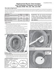
Burner Rack and Components -<br />
Applies to all Furnaces as noted (one per<br />
furnace section)<br />
Codes 180/181, Burner Rack - All Models<br />
185<br />
180/181<br />
184<br />
Carryover<br />
Tube and<br />
Drip Shield<br />
Code 190 - Manifold<br />
Code 200 - Carryover Regulator Assembly for<br />
Propane Gas<br />
200A<br />
Carryover<br />
Tubing -<br />
Natural Gas<br />
201A<br />
200B<br />
201B<br />
200G<br />
201C<br />
Form 707, Page 18<br />
200C<br />
203B<br />
203<br />
187<br />
200F<br />
186<br />
186<br />
200D<br />
193 (not in<br />
Code 200)<br />
200E<br />
188/189<br />
183<br />
202<br />
Code 191- Burner Orifices<br />
Air Shutter Hardware<br />
203D<br />
203A<br />
Code Description<br />
180 Burner Rack Aluminum with Carryovers and Air Shutters<br />
181 Burner Rack Stainless Steel with Carryovers and Air Shutters<br />
Replacement Burner Rack Stainless Steel with Carryovers for<br />
RP units with Gas Control Option AG39 or AG40<br />
182 Flash Carryover (one piece)<br />
183 Flash Carryover Right Section<br />
184 Flash Carryover Center Section<br />
185 Flash Carryover Left Section<br />
186 Carryover Lighter Tube (Tube only)<br />
187 Carryover Lighter Tube Drip Shield<br />
188 Main Burner Tube - Aluminized<br />
189 Main Burner Tube - Stainless Steel<br />
190 Manifold (less orifices)<br />
191 Burner (H)RG; PGBL Natural Gas All Series<br />
Orifice (H)CRG Natural Gas All Series<br />
Drill Size (H)RP Natural Gas Prior to Series 8<br />
Series 8<br />
See (H)CRP Natural Gas Prior to Series 8<br />
table below (H)RG; PGBL Propane Gas All Series<br />
for P/N's. (H)CRG Propane Gas All Series<br />
(H)RP Propane Gas Prior to Series 8<br />
Series 8<br />
(H)CRP Propane Gas Prior to Series 8<br />
193 Carryover (H)RG Natural Gas All Series<br />
Orifice (H)CRG Natural Gas All Series<br />
Drill Size (H)RP Natural Gas Prior to Series 8<br />
Series 8<br />
(H)RP Natural Gas with AG39 or AG40<br />
See (H)CRP Natural Gas Prior to Series 8<br />
table below (H)RG Propane Gas All Series<br />
for P/N's. (H)CRG Propane Gas All Series<br />
(H)RP Propane Gas Prior to Series 8<br />
Series 8<br />
(H)CRP Propane Gas Prior to Series 8<br />
200 Carryover Regulator Assembly (includes Codes 200A-G)<br />
200A Carryover Regulator, Maxitrol RV-12, Propane Gas<br />
Carryover Regulator, Natural Gas with Option AG39 or AG40<br />
200B Carryover Regulator Tubing 1/4" x 5-1/2"<br />
200C Carryover Regulator Tubing 1/4" x 1-1/4"<br />
200D Carryover Regulator Tag<br />
200E Carryover Regulator Fitting (Compression Fitting)<br />
200F Carryover Regulator Fitting, Regulator to Manifold<br />
200G Carryover Regulator Fitting, 90° Brass Elbow<br />
201A Carryover Tubing, Natural Gas<br />
201B Brass Elbow<br />
201C Compression Fitting<br />
202 Burner Rack Isinglass<br />
203A Air Shutter Adjustment Screw, 1/4-20 x 2-1/2" long<br />
203B Air Shutter Screw Nut, 1/4" -20<br />
203C Air Shutter Slide Tinnerman Nut, 1/4"-20 (not illustrated)<br />
203D Air Shutter Adjustment Instruction Tag
500 600 700, 1050 400, 800, 1200<br />
Code 75 100 125 150 175 200 225 250 300 350 400<br />
180 65972 65973 65974 65975 65976<br />
65977 65978<br />
181 65980 65981 65982 65983 65984 65985 65986<br />
-- -- 92813 92814 92814 92815 92815 92816 92816 n 92818<br />
182 63128 63131 63138 -- -- -- -- -- --<br />
183 -- -- -- -- -- 63148 63141 63148 63152<br />
184 -- -- -- -- -- -- --<br />
63156 68071<br />
185 -- -- -- -- --<br />
63144<br />
186 9899 9859 9821 9783 9747 9711 9520<br />
187 15015 15014 15013 15012 15011 15010 14957<br />
188<br />
85218<br />
(4) (4) (5) (7) (7) (9) (9) (12) (12) (14) (16)<br />
189<br />
87954<br />
(4) (4) (5) (7) (7) (9) (9) (12) (12) (14) (16)<br />
190 86338 86339 86340 86342 86343 86344 86345<br />
191 45 41 41 43 41 43 41 44 41 41 41<br />
45 43 43 -- 43 -- 43 45 43 43 43<br />
-- -- 42 44 42 43 42 44 42 42 42<br />
-- -- 42 44 42 43 42 44 42 42 42<br />
-- -- 43 -- 43 -- -- 45 43 -- 43<br />
1.20mm 1.45mm 1.45mm 55 1.45mm 55 1.45mm 55 1.45mm 1.45mm 1.45mm<br />
1.20mm 55 55 -- 55 55 55 1.20mm 55 55 55<br />
-- -- 1.45mm 55 1.45mm 55 1.45mm 55 1.45mm 1.50mm 1.45mm<br />
-- -- 1.45mm 55 1.45mm 55 1.45mm 55 1.45mm 1.50mm 1.45mm<br />
-- -- 55 -- 55 -- -- 1.20mm 55 -- 55<br />
193 70 70 70 65 65 59 59 59 59 54 54<br />
70 70 70 -- 65 -- 59 59 59 54 54<br />
-- -- 70 65 65 65 65 59 59 57 56<br />
-- -- 70 65 65 65 65 59 59 57 56<br />
-- -- 70 65 65 65 65 59 59 n 56<br />
-- -- 70 -- 65 -- -- 59 59 -- 56<br />
70 70 70 65 65 65 65 59 59 56 56<br />
70 70 70 -- 65 -- 65 59 59 56 56<br />
-- -- 70 65 65 65 65 59 59 57 56<br />
-- -- 70 65 65 65 65 59 59 57 56<br />
-- -- 70 -- 65 -- -- 59 59 -- 56<br />
200<br />
100712<br />
200A<br />
11294<br />
11294<br />
200B<br />
9681<br />
200C<br />
11892<br />
200D<br />
11935<br />
200E<br />
9664<br />
200F<br />
1436<br />
200G<br />
18224(2)<br />
201A<br />
93389<br />
201B<br />
93388<br />
201C<br />
9664<br />
202<br />
10756(2)<br />
203A<br />
10653<br />
203B<br />
10650(2)<br />
203C<br />
10651<br />
203D<br />
11934<br />
Main Burner Orifice - Drill Size to P/N<br />
Size 41 42 43 44 45 55 1.20mm 1.45mm 1.50mm<br />
P/N 11792 84437 11828 11833 38678 11830 63003 61652 93410<br />
Carryover Orifice - Drill Size to P/N<br />
Size 70 65 59 57 56 54<br />
P/N 9870 9680 10370 38274 9791 9792<br />
Form 707, Page 19
Gas Train Components<br />
Manual Gas Valves - All Furnaces (Reference: for electric gas valves, see Form RZ 714)<br />
Pilot Shutoff<br />
Valve, P/N 3284<br />
Special Manifolds<br />
Code 223 - Vent Valve,<br />
G/C #S262, P/N 86996<br />
Code 216, 247 - Pilot<br />
Regulator, Maxitrol<br />
R400S, P/N 86965<br />
Form 707, Page 20<br />
Codes211, 212, 224,<br />
240 - Solenoid Valve<br />
Springs for R400S Pilot Regulator<br />
Maxitrol Color Pressure Approx.<br />
P/N Range (w.c.) Length<br />
R400B10-13 Brown 1.0 to 3.5 1-9/16 to 2"<br />
R400B10-25 Cadmium Plate 2.0 to 5.0 1-9/16 to 2"<br />
R400B10-36 Cadmium Plate 3.0 to 6.0 1-9/16 to 2"<br />
R400B10-38 Pink 3.0 to 8.0 1-9/16 to 2"<br />
Illinois School Code Remote Console with Alarm<br />
Bell and Silencing Buttons<br />
218<br />
Console Box,<br />
P/N 107010<br />
Light,<br />
P/N 101889<br />
217<br />
Code 213, 229,<br />
241 - Pilot<br />
Valve Bracket<br />
in Options<br />
BM12, BM13,<br />
BM14<br />
Ball Valve Adapter<br />
1", P/N 110758;<br />
1-1/4", P/N 110759;<br />
1/2", P/N 120373;<br />
3/4", P/N 120169<br />
(1/2" & 3/4" are used with high<br />
and low gas pressure switches,<br />
Options BP2, 3 and 4)<br />
P/N 100262<br />
1/4", P/N 25787<br />
3/4", P/N 88242<br />
1", P/N 112922<br />
125 PSIG Gas Valve<br />
1", P/N 110755;<br />
1-1/4", P/N 110756<br />
P/N's 110758, 110755 and 1/8" pipe plug<br />
(P/N 1028) replace P/N 30257; P/N's<br />
110759, 110756 and 1/8" pipe plug (P/N<br />
1028) replace P/N 89350.<br />
Aluminum Shutoff Valves<br />
1/2", P/N<br />
17019,<br />
with Union,<br />
P/N 15971;<br />
3/4", P/N 1105,<br />
with Union,<br />
P/N 15972<br />
Code Description P/N<br />
Components for Illinois School Code Manifold (Option BM12 is available<br />
on all sizes of RG, RP, RGB, RPB, RGBL, RPBL and PGBL)<br />
205 Low Gas Pressure Switch - see page 9, Codes 8 and 9 149176<br />
206 High Gas Pressure Switch - see page 9, Code 10 93850<br />
207 Vent Limiter, Maxitrol A1209 -see page 9 123481<br />
208 Pressure Switch Brackets (3-7)100261<br />
209 Manual Gas Valve (one per unit) - see page 19 1105 or 17019<br />
210 Manual Pilot Shutoff (one per unit) - see page 19 3284<br />
211 Safety Solenoid Valve (one per unit) 88242<br />
212 Pilot Valve (one per unit) 25787<br />
213 Pilot Valve Bracket 100262<br />
214 Relay SPDT (2)103317<br />
215 Relay SPST 98118<br />
216 Pilot Regulator, Maxitrol 400S 86965<br />
217 Switch Push Button (Alarm Silencing button) 110130<br />
218 Alarm Bell (Adaptable Edwards #340-465, 24V, .31A) 110131<br />
Components for IRI Manifold (Option BM13 is available on Model PGBL<br />
1200 and RPBL 1050 and 1200)<br />
219 Fluid Power Valve (2) 89356<br />
Fluid Power Valve Actuator (2) 86993<br />
220 Low Gas Pressure Switch (see page 9, Codes 8 and 9) 93849<br />
221 High Gas Pressure Switch (see page 9, Code 10) 93850<br />
222 Vent Limiter, Maxitrol A1209 (see page 9) (2)123481<br />
223 Vent Solenoid Valve 86996<br />
224 Pilot Valve (one per unit) 25787<br />
225 Manual Shutoff (one per unit) - see page 19 110756<br />
Ball Valve Adapter (one per unit) - see page 19 110759<br />
226 Pilot Manual Shutoff (one per unit) - see page 19 3284<br />
227 RBM Relay (4)98118<br />
228 Transformer 230/460 to 115V, .5KVA 86997<br />
Transformer 208 to 115V, .5KVA 86998<br />
Transformer 230/460/575 to 115V, 300VA 105202<br />
Transformer 208 to 115V, 250VA 86991<br />
229 Pilot Valve Bracket (2)100262<br />
230 Pilot Regulator (3)86965<br />
231 Valve Box Top 110194<br />
232 Valve Box Inlet Side 110195<br />
233 Valve Box Plain Side 110196<br />
234 Valve Box Back 110197<br />
235 Top Door 110198<br />
236 Bottom Door 110199
Codes 219 and 237<br />
P/N 86993 Actuator<br />
(M/H V4055A1007)<br />
Valve only (used with actuator on the right)<br />
Reznor M/H<br />
Size Gas P/N P/N<br />
1" N or P 86992 V5055A1004<br />
1-1/4" N or P 89356 V5055A1012<br />
2" N or P 91079 V5055A1038<br />
Codes 205-218 - Illinois School Code, Option BM12 (applies to<br />
Model Series RGB/RPB/RGBL/RPBL/PGBL)<br />
Pilot High Pressure<br />
(Natural 12” w.c. minimum; Propane 15” w.c. minimum)<br />
Main Burner Low Pressure<br />
(Natural 5” w.c. minimum;<br />
Propane 11” w.c. minimum)<br />
To<br />
pilot<br />
216<br />
212<br />
(Pilot port is plugged)<br />
Redundant valve<br />
205<br />
Safety<br />
valve<br />
Gas Supply Regulators<br />
1<br />
4<br />
5<br />
3<br />
2<br />
210<br />
Incoming Gas<br />
Manual Shutoff Valve<br />
206<br />
Main Burner High<br />
Pressure (Natural 4” w.c.<br />
minimum; Propane 9”<br />
w.c. minimum)<br />
Key:<br />
NO = Normally Open<br />
NC = Normally Closed<br />
Components for FM Manifold (Option BM14 is available with RPBL and<br />
(C)RGBL 500 - 1200 and PGBL 800 and 1200)<br />
237 Fluid Power Valve 89356<br />
Fluid Power Valve Actuator 86993<br />
238 Manual Shutoff (one per unit) - see page 19 110756<br />
Ball Valve Adapter (one per unit) - see page 19 110759<br />
239 Pilot Manual Shutoff (one per unit) - see page 19 3284<br />
240 Pilot Valve (one per furnace) 25787<br />
241 Pilot Valve Bracket 100262<br />
242 Pilot Regulator 86965<br />
243 Transformer 230/460/575 to 115V, 300VA 105202<br />
Transformer 208 to 115V, 250VA 86991<br />
244 Valve Box Top 110211<br />
245 Valve Box Inlet Side 110195<br />
246 Valve Box Plain Side 110196<br />
247 Valve Box Back 110212<br />
248 Top Door 110213<br />
249 Bottom Door 110214<br />
Codes 219-236 - IRI, Option BM13 (applies to<br />
Model RPBL 1050 and 1200 and Model PGBL<br />
1200)<br />
221<br />
Codes 237-249 -<br />
FM, Option<br />
BM14 (applies to<br />
Model Series<br />
RPBL and<br />
PGBL)<br />
219<br />
226<br />
Branch Tee, P/N 96809<br />
226<br />
Pipe Size 1" 1-1/2"<br />
Option No. CZ1 CZ2<br />
Package P/N 124258 124259<br />
Code Components Qty P/N P/N<br />
1 Maxitrol Regulator 1 124254 124255<br />
Model 210DZ Model 210EZ<br />
2 Hex Bushing (black iron) 1 8643 124256<br />
3/8" x 1/8" 3/4" x 1/8"<br />
3 1/8" x 2-1/2" Brass Nipple 3 107122 107122<br />
4 1/8", 90 ° Brass Elbows 2 124257 124257<br />
5 Insect ScreenAssy 1 96793 96793<br />
Settings<br />
Natural 4”<br />
Propane 9”<br />
237<br />
228<br />
Vent Pipe<br />
239<br />
Branch Tee, P/N 96809<br />
239<br />
219<br />
Branch Tee, P/N 96809<br />
226<br />
239<br />
225<br />
328<br />
Form 707, Page 21
Cabinet Parts for "B" Type Blower Cabinet Section - Applies to Model Series RGB and RPB<br />
256<br />
250<br />
Filter Rack and Blockoff Plates<br />
Form 707, Page 22<br />
253<br />
258<br />
252<br />
251<br />
260<br />
259<br />
For Replacement P/N's for Blockoff Plates and Filters, see page 45.<br />
Cross-Reference of End and Bottom<br />
Panel Options to Cabinet Openings<br />
End Panel Btm Pnl<br />
Cabinet 30% 100% 100%<br />
Option Open Solid Open Solid Open<br />
Std X X<br />
AR-4 X X<br />
AR-6 X X<br />
AR-8 X X<br />
AR-9 X X<br />
AR-11 X X<br />
AR-12 X X<br />
AR-13 X X<br />
AR-14 X X<br />
AR-15 X X<br />
AR-16 X X<br />
AR-17 X X<br />
AR-18 X X<br />
AR-23 X X<br />
AR-24 X X<br />
D1 X X<br />
D2 X X<br />
D3 X X<br />
D4 X X<br />
Horizontal<br />
Blockoff<br />
Plate<br />
Replacement<br />
Door Latch<br />
Kit, P/N<br />
112974<br />
Vertical<br />
Blockoff<br />
Plate<br />
(For Models RBA<br />
and RBHA,<br />
see page 52.)<br />
Assembly sequence for installing<br />
replacement door latch.<br />
(2) Water Resistant<br />
Neoprene Washers<br />
Metal<br />
Washer<br />
Shaft with<br />
Slotted Head<br />
with Directional<br />
Arrow<br />
Retainer<br />
Pawl<br />
Set<br />
Screw<br />
1/4” Mounting<br />
Hole<br />
Door<br />
Panel<br />
Code Description 75/100 125 150/175 200/225 250/300 350 400<br />
250 End Panel Assy - solid (no opening) 103617 103617 103618 103619 103620 103621 103622<br />
End Panel Assy - solid (no opening) w/double-wall construction (Opt AY3) 105547 105547 105548 105549 105550 105551 105552<br />
End Panel Assy - 30% opening 105111 105111 105112 105113 105114 105115 105116<br />
End Panel Assy - 30% opening w/double-wall construction (Opt AY3) 105553 105553 105554 105555 105556 105557 105558<br />
End Panel Assy - 100% opening 103638 103638 103639 103640 103641 103642 103643<br />
End Panel Assy - 100% opening w/double-wall construction (Opt AY3) 105541 105541 105542 105543 105544 105545 105546<br />
251 Bottom Panel Assy - solid (no opening) 103752 103752 103753 103754 103755 103756 103757<br />
Bottom Panel Insulation Retainer - solid (no opening) 110963 110963 110964 110965 110966 110967 110968<br />
Bottom Panel Assy - 100% opening 103562 103562 103563 103564 103565 103566 103567<br />
Bottom Panel Insulation Retainer - 100% opening 110970 110970 110971 110972 110973 110974 110975<br />
252 Blower Door - standard<br />
(2)100347<br />
Blower Door - w/double-wall construction (Opt AY3)<br />
(2)104115<br />
253 Blower Cabinet Top Assy 103598 103598 103599 103600 103601 103602 103603<br />
254 Blower Cabinet Top Insulation Retainer 100246 100246 100247 100248 100249 100250 100251<br />
255 Corner Post<br />
(2)114761<br />
256 Corner Post Cap<br />
(2)100072<br />
257 Cabinet Leg<br />
(2)100027<br />
258 Cabinet Leg Cap Right<br />
100069<br />
259 Cabinet Leg Cap Left 100071
Code Description 75/100 125 150/175 200/225 250/300 350 400<br />
260 Filter Rack Middle Assy 104058 104059 104060 104061 104062 104063<br />
261 Fltr Rck Btm Assy - std left side controls 104072 104073 104074 104075 104076 104077<br />
Fltr Rck Btm Assy - optional right side cntrls 105282 105283 105284 105285 105286 105287<br />
262 End Panel and Filter Support Assy 104079 104080 104081 104082 104083 104084<br />
265 Blower Top Door Seal Angle (2)111023<br />
(2)111024<br />
266 Top End Panel Seal Angle 110977 110978 110979 110980 110981 110982<br />
270A Blower - Housing, Shaft, Wheel & Bearings 1357, Lau A10-10AC 1360, Lau A12-12AC -- -- --<br />
270B Blower - Right Hand Housing & Wheel only -- -- -- -- 24229, Lau 2A10-10A 24231, Lau 2A12-12A<br />
270C Blower - Left Hand Housing & Wheel only -- -- -- -- 24230, Lau 2A10-10A 24232, Lau 2A12-12A<br />
271 Blower Shaft 11302, 3/4 x 22 11303, 1 x 22 10120, 1 x 39-1/4 10121, 1 x 44-5/8<br />
272 Blower Shaft Bearings<br />
(2)7310 (2)10437<br />
273 Mtr Adjustment Brckt Assy - 1/4-3/4 HP Mtrs<br />
44411<br />
273A Hardware Bag only for Code 273<br />
64940<br />
274 Motor Mounting Strap - for 1/4 - 3/4 HP Mtrs 44409 - 10" 44410 - 12" 44409 - 10"<br />
44410 - 12"<br />
275 Motor Mounting Plate - 1-3HP Motor 12578 12579 12578<br />
12579<br />
Motor Mounting Plate - 5HP Motor -- --<br />
12578<br />
276 Motor Left Support - 1-5 HP Motor<br />
12576<br />
277 Motor Right Support -1-5 HP Motor<br />
12577<br />
278 Rod Bolt for Mtr Mntng - 1-5 HP Motor<br />
(2)12489<br />
279 Adapter Back for Blower 193986 194054 194093 193988 194062 194064<br />
280 Blower Adapter Top and Bottom (2)53277 -- -- -- -- -- --<br />
281 Blower Adapter Sides (2)53278 -- -- -- -- -- --<br />
282 Blower Key<br />
19361<br />
Blower Adapter<br />
- Sizes 75-100<br />
279<br />
Left and Right<br />
Blowers (Sizes<br />
250-400) with a<br />
1-5 HP Motor<br />
270B<br />
281<br />
280<br />
Blower with a 1/4 - 3/4 HP Motor<br />
Horizontal Shipping<br />
Brace, P/N 31576<br />
279<br />
271<br />
274 282<br />
270C<br />
Motor,<br />
see pages<br />
32-35.<br />
273<br />
Drives, see<br />
pages 37 -<br />
44.<br />
Code 273 -<br />
Adjustment<br />
Bracket and<br />
Hardware for<br />
1/4 - 3/4 HP<br />
Motor<br />
Code 273A<br />
5/16 - 18 x 4” Lg<br />
Hex Head Bolt<br />
5/16 - 18<br />
Lock Nut<br />
5/16 - 18 x 3/ 4” Lg<br />
Square Head Bolt<br />
Rubber<br />
Grommet<br />
Code 274 - for 1/4 -<br />
3/4 HP Motor<br />
5/16 - 18<br />
Hex Nut<br />
Mounting Plate and Hardware for 1 - 5<br />
HP Motor<br />
(6) Bolts<br />
P/N 16247<br />
277<br />
(2) Bolts<br />
P/N 16248<br />
275<br />
278(2)<br />
276<br />
(6) Nuts, P/N 6554<br />
(6) Washers, P/N 1087<br />
(4) Threaded Inserts,<br />
P/N 124260<br />
Form 707, Page 23
Cabinet Parts for "BL" Type Blower Cabinet Section - Applies to RGBL, RPBL and PGBL (For<br />
Model RBL cabinet parts, see page 52.)<br />
Code Description 500/600 700/1050 400/800/1200<br />
300 Cabinet Btm - Right Half - solid (no opening) 106242<br />
106244<br />
Cabinet Btm - Left Half - solid (no opening) 106238 106239 106240<br />
Cabinet Btm - Right Half - return air opening 105606 105607 105608<br />
Cabinet Btm - Left Half - return air opening 104365 104366 104367<br />
301 End Panel Assy - solid (no opening) 103620 103621 103622<br />
End Pnl Assy - solid (no opening) w/double-wall cnstrctn (Opt AY3) 105550 105551 105552<br />
End Panel Assy - 30% opening 105114 105115 105116<br />
End Pnl Assy - 30% opening w/double-wall construction (Opt AY3) 105556 105557 105558<br />
End Panel Assy - 100% opening 103641 103642 103643<br />
End Pnl Assy - 100% opening w/double-wall construction (Opt AY3) 105544 105545 105546<br />
302 Blower Door - standard<br />
(2)100347<br />
Blwr Door - w/double-wall construction (Opt AY3)<br />
(2)104115<br />
303 Filter Cabinet Door Assy<br />
(2)106276<br />
Fltr Cbnt Dr Assy - w/double-wall construction (Opt AY3)<br />
(2)107350<br />
304 Blower Cabinet Front Top Section Assy 106280 106281 106282<br />
Blower Cabinet Rear Top Section Assy 106286 106287 106288<br />
305 Blower Cabinet Top Insulation Retainer 107350 107351 107352<br />
306 Filter Cabinet Top Insulation Retainer 107354 107355 107356<br />
307 BL Cabinet Leg #1, Left<br />
105603<br />
308 BL Cabinet Leg #2, Right<br />
105604<br />
309 Corner Post<br />
(2)114761<br />
310 Cabinet Leg Cap Left<br />
100069<br />
311 Cabinet Leg Cap Right<br />
100071<br />
312 Cabinet Intermediate Post<br />
(2)114762<br />
313 Cabinet Intermediate Post Cap<br />
(2)104372<br />
314 Corner Post Cap<br />
(2)100072<br />
315 Cabinet Top Front Panel 105610 105611 105612<br />
316 Cabinet Bottom Front Panel 105614 105615 105616<br />
317 Cabinet Vertical Blower Support Left<br />
106299<br />
318 Cabinet Vertical Blower Support Right<br />
106943<br />
319 Cabinet Horizontal Blower Support<br />
(2)31576<br />
320 Cabinet and Panel Support 100078 100079 10080<br />
321 Cabinet Top Support 105600 105601 105602<br />
322 Cabinet Bottom Filter Rack Assy Mfgd prior to 9/91 w/std left side controls 106314 106315 106316<br />
for 1 & 2" filters<br />
Mfgd prior to 9/91 w/optl right side cntrls 110016 110017 110018<br />
Mfgd beginning 9/91 - all 114711 114712 114713<br />
323 Cabinet Rear Filter Rack Assy Mfgd prior to 9/91 (2)106317 (2)106318 (2)106319<br />
for 1 & 2" filters Mfgd beginning 9/91 (2)114707 (2)114708 (2)114709<br />
324 Cabinet Front Filter Rack Assy Mfgd prior to 9/91 106320 106321 106322<br />
for 1 & 2" filters Mfgd beginning 9/91 (2)114695 (2)114696 (2)114697<br />
325 Cabinet Top Filter Rack Assy Mfgd prior to 9/91 106325 106326 106327<br />
for 1 & 2" filters Mfgd beginning 9/91 114719 114720 114721<br />
326 1" Filter Clamp Apply only -- -- (3)106248<br />
1" Filter Clamp to units<br />
(6)106323<br />
327 2" Filter Clamp manufactured -- -- (3)106229<br />
2" Filter Clamp prior to 9/91<br />
(6)106324<br />
328 Top Door Seal<br />
(2)95487<br />
329 BL Blower Cabinet Adapter RGBL, RPBL, RBL 163833 163834 106294<br />
Back Assembly PGBL -- -- 148429<br />
Form 707, Page 24
"BL" Blower Cabinet<br />
316<br />
304<br />
Replacement<br />
Door Latch<br />
Kit, P/N<br />
112974<br />
317<br />
Assembly<br />
sequence for<br />
installing<br />
replacement<br />
door latch.<br />
302<br />
303<br />
View of a "BL" Type Blower Cabinet with the Access Panels Removed<br />
For replacement filters and blockoff plates, see pages 45 and 46.<br />
Cross-Reference of End and Bottom<br />
Panel Options to Cabinet Openings<br />
End Panel Btm Panel<br />
Cabinet 30% 100% 100%<br />
Option Open Solid Open Solid Open<br />
Std X X<br />
AR-4 X X<br />
AR-6 X X<br />
AR-7 X X<br />
AR-8 X X<br />
AR-9 X X<br />
AR-11 X X<br />
AR-12 X X<br />
AR-13 X X<br />
AR-14 X X<br />
AR-15 X X<br />
AR-16 X X<br />
AR-17 X X<br />
AR-18 X X<br />
AR-23 X X<br />
AR-24 X X<br />
D1 X X<br />
D2 X X<br />
D3 X X<br />
D4 X X<br />
Form 707, Page 25
Parts for "BL" Type Blower Cabinet Section (cont'd) - Applies to RGBL, RPBL and PGBL (For<br />
Model RBL, see page 60.)<br />
Code Description Qty 500/600 700/1050 400/800/1200<br />
330 BL Cabinet Motor Mounting Plate Assembly 1<br />
106295<br />
331 BL Cabinet Motor Mounting Support<br />
< 15HP motor 2<br />
106698<br />
Assembly<br />
15 & 20 HP and all units with<br />
Option PC12, vibration isolation<br />
1<br />
149008<br />
332 BL Cabinet Motor Adjustment Angle<br />
< 15HP motor 1<br />
105633<br />
333<br />
334<br />
Motor Adjustment Bolt 3/8 - 16 x 7" long<br />
Adjustment Bolt Hex Nut 3/8 - 16<br />
15 & 20 HP and all units with<br />
Option PC12, vibration isolation<br />
1<br />
1<br />
1<br />
149010<br />
106275<br />
1438<br />
335 BL Cabinet Blower (Housing and Wheel )Lau 15 x 9, 1-3/16 2 106296 -- --<br />
336 BL Cabinet Blower (Housing and Wheel ) Lau 15 x 11, 1-3/16 2 --<br />
14469<br />
337 Blower Shaft 1-3/16 x 37" long 1 106297 -- --<br />
Blower Shaft 1-3/16 x 42-1/2" long 1 -- 106298 --<br />
Blower Shaft 1-3/16 x 48" long 1 -- -- 13589<br />
338 Blower Bearing FAFAIR 1-3/16" #E8317 2<br />
14474<br />
339 Vertical Blower Support - Right 1<br />
106943<br />
340 Vertical Blower Support - Left 1<br />
106299<br />
341 Bearing Bracket, 1-3/16, Lau #014431-02 2<br />
24233<br />
342 Heavy Duty Blower Right Lau 15 x 9 (15-20HP motors) 1 106935 -- --<br />
343 Heavy Duty Blower Left Lau 15 x 9 (15-20HP motors) 1 106936 -- --<br />
344 Heavy Duty Blower Right Lau 15 x 11 (15-20HP motors) 1 --<br />
106937<br />
345 Heavy Duty Blower Left Lau 15 x 11 (15-20HP motors) 1 --<br />
106938<br />
346 Blower Shaft Key (used with heavy duty blowers) 4<br />
134638<br />
347 Blower Shaft Heavy Duty Blower 1-7/16 x 42" long 1 106939 -- --<br />
Blower Shaft Heavy Duty Blower 1-7/16 x 47-1/2" long 1 -- 106940 --<br />
Blower Shaft Heavy Duty Blower 1-7/16 x 53" long 1 -- -- 106941<br />
348 Pillow Block Bearing, 1-7/16 Bore, Dodge P2BS2107R (replaces P/N 106942) 2<br />
170108<br />
349 Class II Blower Support - Right Side 1<br />
149520<br />
350 Class II Blower Support - Left Side 1<br />
149521<br />
351 Air Flow Switch Pitot Sense Probe (part of Option BW1) - see illustration on<br />
page 27<br />
1<br />
111733<br />
Form 707, Page 26<br />
Blower, Bearing Support and<br />
Motor on unit with up to a 5<br />
HP Motor<br />
340<br />
331
Blower Triangular Bearing Mounting for RGBL/<br />
RPBL/PGBL with a 7-1/2 or 10 HP Motor<br />
Description P/N<br />
Left Bearing support Assy 112971<br />
Right Bearing Support Assy 112972<br />
Pillowblock Bearing Sealmaster 1/16" (2)112973<br />
1/2-13 x 2" Cap Screw GR-8 (4)111304<br />
1/2-13 Nut GR-8 (4)111305<br />
1/2 Lockwasher (4)111306<br />
1/4-20 Cap Screws (6)16246<br />
1/4-20 Lock Nut (6)10650<br />
Blower and Bearing on a unit with<br />
a 15 and 20 HP Motor<br />
Motor Mounting Bolts<br />
3/8" Bolt<br />
Motor Mounting Base<br />
Star Washer<br />
P/N 112571<br />
5/16" Bolt<br />
Motor Mounting Base<br />
Star Washer<br />
P/N 112573<br />
Location of Air Flow<br />
Switch Sensor<br />
Code 351 - Sensing<br />
Tube Assembly,<br />
P/N 111733<br />
Airflow<br />
Retaining Clip,<br />
P/N 112570<br />
3/8 Bolt,<br />
P/N 32253<br />
Retaining Clip,<br />
P/N 112572<br />
5/16 Bolt,<br />
P/N 16247<br />
IMPORTANT: Sensing tube<br />
must point into airflow.<br />
1”<br />
10”<br />
Form 707, Page 27
Dampers and Controls - Applies to all Packaged Systems and Blower Cabinet Models RBA and<br />
RBL<br />
Model<br />
RBA<br />
500,<br />
600<br />
700,<br />
1050<br />
400, 800,<br />
1200,<br />
RBL<br />
(NOTE: P/N's for Code 361 are for the<br />
damper and frame assembly only; for<br />
linkage and motor, see Codes 364-393.)<br />
Code Description<br />
75,<br />
100,<br />
125<br />
150,<br />
175<br />
200,<br />
225<br />
250,<br />
300<br />
350 400<br />
Damper and Frame Assembly<br />
only for 30% Outside Air<br />
361<br />
360 Dampers (see illustration of<br />
30% damper on bottom of<br />
page)<br />
120552 120553 120554 120555 120556 120557<br />
361<br />
Damper and Frame Assembly<br />
only for 100% Outside Air or<br />
Return Air Dampers<br />
Form 707, Page 28<br />
105421 105422 105423 105424 105425 105426<br />
Components by Option Description - Option AR__<br />
Code Description P/N 6 7 8 9 11 12 13 14 15 16 17 18 23<br />
362 Hand Quadrant #14004728-001 103502 X X<br />
363 Manual Damper Control Bracket (replaces P/N 103488) 143182 X X<br />
364 2-Position Damper Motor (with one end<br />
switch)<br />
66276 X X X X<br />
365 Optional 2-position Dmpr Mtr, #W/R-3402-9 (2 end<br />
switches)<br />
97385 X X X X<br />
366 Modulating Damper Motor, #M9175A1051 (no end<br />
switch)<br />
115681 X X X X X X<br />
367 Optional Modulating Damper Motor, #M9175D1014<br />
(2 end switches)<br />
115682 X X X X X X<br />
368 Floating Modulating Damper Motor, #M619AB1011 115683 X<br />
369 Damper Rod, 1/4 x 12 " Lg 11561 X X X X X X X X<br />
370 Damper Rod, 1/4 x 16 " Lg 112555 X X<br />
371 Damper Rod, 1/4 x 17 " Lg 112556 X X X X X X X X<br />
372 Damper Rod, 1/4 x 22 " Lg 26299 X<br />
373 Damper Rod, Bent 105420 X<br />
374 Damper Rod Arm, W-R #135-0007 See 66278 X<br />
375 Crank Arm, W/R #135-0002 Damper 66277 X<br />
376 Crank Arm, W/R #135-0003 Rigging, 112553 X X X<br />
377 Damper Arm, M/H #20265 pages 30 - 12635 X X X (2) X (2) X (2) X X (2) X (2) X X (2) X (2)<br />
378 Ball and Socket, M/H #27518 32.<br />
12636 X X(2) X(2) X(2) X (4) X (4) X (4) X (4) X (4) X(4) X (4) X (4)<br />
380 Crank Arm M/H #221455A 116209 X X X X X X X<br />
382 Damper Arm Support Plate 14225 X X X<br />
383 Damper Motor Support Assy 100315 X X X X X X X X X X X<br />
384 Damper Arm Adjustment Plate 115687 X X X X X<br />
385 Damper Arm Adjustment Plate 142982 X<br />
386 Air Controller Support Bracket 103758 X X X X X X<br />
387 Potentiometer, M/H #112894FA 16110 X X X X<br />
388 Mixed Air Controller, M/H #T991A-1004 16109 X X X X<br />
389 Outdoor Air Controller, J/C#A19AAF-120 126170 X X X<br />
390 Null Switch (pressure), Dwyer #1640 88052 X<br />
391 Auxiliary End Switch only for M/H Damper Motors, 113963<br />
392<br />
#Q607B1067<br />
Auxiliary Switch Kit (2 switches), M/H 220736B 145881<br />
393 DDC (4-20ma) interface module for use with<br />
modulating damper motor, Honeywell Q7230A<br />
171134<br />
361<br />
Code 362 - Hand<br />
Quadrant, P/N<br />
103502, (on a 30%<br />
Outside Air Damper)<br />
Code 363 - Manual<br />
Damper Control<br />
Bracket, P/N 175248
Damper and Control Locations<br />
Horizontal (outside air) Damper<br />
Damper<br />
Motor<br />
Code 391 - Auxiliary<br />
End Switch,<br />
P/N 113963,<br />
M/H Q607B1067<br />
385 388 389<br />
Vertical (return<br />
air) Damper<br />
Damper Linkage (see pages 30-32)<br />
NOTE: Crank Arm Code 380 is used with<br />
motors P/N 115682, 115683, and 115681<br />
(motors used in currently manufactured<br />
units)<br />
Use Crank Arm P/N 20874 (illustrated) ,<br />
M/H #7616BR, with motors P/N 53928,<br />
87059 and 96767<br />
Code 387 - Potentiometer,<br />
M/H 112894FA,<br />
P/N 16110<br />
Code 388 - Mixed Air<br />
Controller, M/H T991-<br />
1004, P/N 16109<br />
Grommet Clamp,<br />
P/N 39224<br />
Code 364 - Damper Motor for 2-<br />
Position Damper (open/closed),<br />
W/R 3405-21 with one end<br />
switch, P/N 66276<br />
Code 365 (illustrated), Damper<br />
Motor for 2-Position Damper<br />
(open/closed), W/R 3402-09 with<br />
two end switches, P/N 97385<br />
Code 366 - Modulating Damper<br />
Motor, M/H M9175A1051 less end<br />
switches, P/N 115681 (replaces P/N<br />
53928)<br />
Code 367 (illustrated) - Modulating<br />
Damper Motor, M/H M9175D1014<br />
with two end switches, P/N 115682<br />
(replaces P/N 96767)<br />
Code 368 - Modulating Damper<br />
Motor used in Option AR23,<br />
M/H #M6294B1011, P/N 115683,<br />
(with pressure null switch)<br />
35°<br />
Code 389 - Outside<br />
Air Controller,<br />
J/C#A19AAF-120,<br />
P/N 126170 (replaces<br />
P/N 16108)<br />
7”<br />
Code 390 - Pressure<br />
Null Switch, Dwyer<br />
#1640-0, Range<br />
.01" to .2" w.c.,<br />
P/N 88052<br />
9-3/4”<br />
Bent Damper Rod<br />
374 375/376<br />
377<br />
P/N<br />
20874<br />
380 (see<br />
note on<br />
the left)<br />
382<br />
378<br />
Code 393 - DDC<br />
(4-20 ma)<br />
interface module<br />
for modulating<br />
damper motor,<br />
P/N 171134,<br />
M/H Q7230A<br />
1/4”<br />
Code - 373<br />
Form 707, Page 29
Damper Rigging<br />
Form 707, Page 30
Form 707, Page 31
Damper Rigging (cont'd)<br />
Replacement Blower Motors and Starters<br />
Replacement Motors (Tables on pages 33-36)<br />
Motors in the Open, TEFC and Premium Efficiency tables that are highlighted in<br />
gray do not have internal overload protection and must be used with the motor<br />
starter and overload listed. See Code 28A, page 9, for standard motor contactor for<br />
motors with internal overloads.<br />
Replacement IEC Starters and Overloads (listed by motor in the tables<br />
on pages 33-36)<br />
When ordering a replacement IEC starter (contactor) or overload, check the<br />
manufacturer's number on both parts. If the number is different than that listed,<br />
both components must be replaced. IEC Starter (contactor) and overload are<br />
mounted on rail, P/N 111387. Replacement holding coils are listed on page 36.<br />
If the motor has a NEMA starter, see the replacement parts on page 37.<br />
Form 707, Page 32<br />
IEC Starter<br />
(Contactor)<br />
IEC<br />
Adjustable<br />
Overload
Open Dripproof Motors<br />
NOTE: Two-speed motors are on page 36.<br />
Motor Reznor Replaces Contactor Reznor Overload Reznor<br />
Type HP Mfr FLA Mfr No. P/N P/N V ph GE # P/N GE # Min Max P/N<br />
OPEN 1/4 A.O.Smith 5.1 316P260 93545 120 1 CL00A310T-J 151146 RT A1-L 4 6.3 151191<br />
OPEN 1/4 A.O.Smith 2.1 325P163 115790 85087 208 1 CL00A310T-L 151150 RT A1-J 1.9 2.7 151189<br />
OPEN 1/4 A.O.Smith 2.3 325P163 115790 85087 240 1 CL00A310T-S 151147 RT A1-J 1.9 2.7 151189<br />
OPEN 1/4 Century 1.1 H200 115864 208 3 CL00A310T-L 151150 RT A1-G 1 1.5 151187<br />
OPEN 1/4 Century 1.4 H200 115864 240 3 CL00A310T-S 151147 RT A1-G 1 1.5 151187<br />
OPEN 1/4 Century 0.75 H200 115864 480 3 CL00A310T-U 151148 RT A1-F 0.6 1.1 151186<br />
OPEN 1/3 A.O.Smith 5.5 316P308 93546 120 1 CL00A310T-J 151146 RT A1-L 4 6.3 151191<br />
OPEN 1/3 Century 3.2 F153 115862 7802 208 1 CL00A310T-L 151150 RT A1-K 2.5 4 151190<br />
OPEN 1/3 Century 2.8 F153 115862 7802 240 1 CL00A310T-S 151147 RT A1-K 2.5 4 151190<br />
OPEN 1/3 Century 1.4 H260 115863 208 3 CL00A310T-L 151150 RT A1-G 1 1.5 151187<br />
OPEN 1/3 Century 1.6 H260 115863 240 3 CL00A310T-S 151147 RT A1-H 1.3 1.9 151188<br />
OPEN 1/3 Century 0.8 H260 115863 480 3 CL00A310T-U 151148 RT A1-F 0.6 1.1 151186<br />
OPEN 1/2 Century 8.8 327P828 102627 120 1 CL00A310T-J 151146 RT A1-N 7 10 151193<br />
OPEN 1/2 A.O.Smith 5.1 327P828 102627 208 1 CL00A310T-L 151150 RT A1-L 4 6.3 151191<br />
OPEN 1/2 A.O.Smith 4.4 327P828 102627 240 1 CL00A310T-S 151147 RT A1-L 4 6.3 151191<br />
OPEN 1/2 Century 3 H880 159183 13443 208 3 CL00A310T-L 151150 RT A1-K 2.5 4 151190<br />
OPEN 1/2 Century 2.5 H880 159183 13443 240 3 CL00A310T-S 151147 RT A1-K 2.5 4 151190<br />
OPEN 1/2 Century 1 H880 159183 13443 480 3 CL00A310T-U 151148 RT A1-G 1 1.5 151187<br />
OPEN 3/4 A.O.Smith 11 312P629 93548 120 1 CL01A310T-J 151151 RTA1-P 10 16 151194<br />
OPEN 3/4 A.O.Smith 6.3 312P629 93548 208 1 CL00A310T-L 151150 RT A1-M 5.5 7.5 151192<br />
OPEN 3/4 A.O.Smith 5.5 312P629 93548 240 1 CL00A310T-S 151147 RT A1-L 4 6.3 151191<br />
OPEN 3/4 A.O.Smith 2.9 312P696 36951 208 3 CL00A310T-L 151150 RT A1-K 2.5 4 151190<br />
OPEN 3/4 A.O.Smith 2.6 312P696 36951 240 3 CL00A310T-S 151147 RT A1-K 2.5 4 151190<br />
OPEN 3/4 A.O.Smith 1.3 312P696 36951 480 3 CL00A310T-U 151148 RT A1-G 1 1.5 151187<br />
OPEN 1 A.O.Smith 13 327P297 13685 120 1 CL01A310T-J 151151 RTA1-P 10 16 151194<br />
OPEN 1 A.O.Smith 7.5 327P297 13685 208 1 CL00A310T-L 151150 RT A1-M 5.5 7.5 151192<br />
OPEN 1 A.O.Smith 6.5 327P297 13685 240 1 CL00A310T-S 151147 RT A1-M 5.5 7.5 151192<br />
OPEN 1 A.O.Smith 3.7 312P703 36580 208 3 CL00A310T-L 151150 RT A1-K 2.5 4 151190<br />
OPEN 1 A.O.Smith 3.2 312P703 36580 240 3 CL00A310T-S 151147 RT A1-K 2.5 4 151190<br />
OPEN 1 A.O.Smith 1.6 312P703 36580 480 3 CL00A310T-U 151148 RT A1-H 1.3 1.9 151188<br />
OPEN 1 Century 1.1 E1006 158175 105533 575 3 CL00A310T-Y 151149 RT A1-G 1 1.5 151187<br />
OPEN 1.5 Century 15 C688 105527 120 1 CL02A310T-J 151156 RTA1-P 10 16 151194<br />
OPEN 1.5 A.O.Smith 8.3 311P763 4082 208 1 CL00A310T-L 151150 RT A1-N 7 10 151193<br />
OPEN 1.5 A.O.Smith 7.5 311P763 4082 240 1 CL00A310T-S 151147 RT A1-M 5.5 7.5 151192<br />
OPEN 1.5 Century 5.6 H884 115859 16081 208 3 CL00A310T-L 151150 RT A1-L 4 6.3 151191<br />
OPEN 1.5 Century 5 H884 115859 16081 240 3 CL00A310T-S 151147 RT A1-L 4 6.3 151191<br />
OPEN 1.5 Century 2.7 H884 115859 16081 480 3 CL00A310T-U 151148 RT A1-J 1.9 2.7 151189<br />
OPEN 1.5 Century 1.6 E1007 158162 105534 575 3 CL00A310T-Y 151149 RT A1-H 1.3 1.9 151188<br />
OPEN 2 Century 20.4 V102 105528 120 1 CL25A310T-J 151160 RTA1-T 17.5 22 151197<br />
OPEN 2 Century 10 V102 105528 208 1 CL01A310T-L 151155 RT A1-N 7 10 151193<br />
OPEN 2 Century 10.2 V102 105528 240 1 CL01A310T-S 151152 RTA1-P 10 16 151194<br />
OPEN 2 Century 7 H886 159327 13697 208 3 CL00A310T-L 151150 RT A1-M 5.5 7.5 151192<br />
OPEN 2 Century 6.6 H886 159327 13697 240 3 CL00A310T-S 151147 RT A1-M 5.5 7.5 151192<br />
OPEN 2 Century 3.5 H886 159327 13697 480 3 CL00A310T-U 151148 RT A1-K 2.5 4 151190<br />
OPEN 2 Century 2.1 E1008 158176 105535 575 3 CL00A310T-Y 151149 RT A1-J 1.9 2.7 151189<br />
OPEN 3 Century 14 B735 111560 31693 208 1 CL02A310T-L 151159 RTA1-P 10 16 151194<br />
OPEN 3 Century 12.4 B735 111560 31692 240 1 CL01A310T-S 151152 RTA1-P 10 16 151194<br />
OPEN 3 Century 9 H845 159185 31692 208 3 CL00A310T-L 151150 RT A1-N 7 10 151193<br />
OPEN 3 Century 8.6 H845 159185 240 3 CL00A310T-S 151147 RT A1-N 7 10 151193<br />
OPEN 3 Century 4.3 H845 159185 480 3 CL00A310T-U 151148 RT A1-L 4 6.3 151191<br />
OPEN 3 Century 3.6 181532-01 120019 575 3 CL00A310T-Y 151149 RT A1-K 2.5 4 151190<br />
OPEN 5 Century 28 V211 111562 208 1 CL04A310M-L 151169 RTA1-V 25 32 151199<br />
OPEN 5 Century 26 V211 111562 111563 240 1 CL04A310M-S 151166 RTA1-V 25 32 151199<br />
OPEN 5 Century 13.4 181159-01 113371 85748 208 3 CL01A310T-L 151155 RTA1-P 10 16 151194<br />
OPEN 5 Century 13.2 8-181159-01 113371 85748 240 3 CL01A310T-S 151152 RTA1-P 10 16 151194<br />
OPEN 5 Century 6.6 8-181159-01 113371 85748 480 3 CL00A310T-U 151148 RT A1-M 5.5 7.5 151192<br />
OPEN 5 Century 5.4 8-181533-01 120020 105829 575 3 CL00A310T-Y 151149 RT A1-L 4 6.3 151191<br />
OPEN 7.5 Century 35 V305 105828 208 1 CL06A311M-L 151173 RTA2-E 32 41 151206<br />
OPEN 7.5 Century 32 V305 105828 240 1 CL45A310M-S 151170 RTA1-V 25 32 151199<br />
OPEN 7.5 Century 22.5 E302 105854 85748 208 3 CL25A310T-L 151164 RTA1-U 21 26 151198<br />
Form 707, Page 33
Replacement Motors and Starters (cont'd)<br />
Open Dripproof Motors (cont'd)<br />
Motor Reznor Replaces Contactor Reznor Overload Reznor<br />
Type HP Mfr FLA Mfr No. P/N P/N V ph GE # P/N GE # Min Max P/N<br />
OPEN 7.5 Century 19.4 E300 105855 85748 240 3 CL25A310T-S 151161 RTA1-T 17.5 22 151197<br />
OPEN 7.5 Century 9.7 E300 105855 85748 480 3 CL01A310T-U 151153 RT A1-N 7 10 151193<br />
OPEN 7.5 Century 7.8 E324 158164 105829 575 3 CL00A310T-Y 151149 RT A1-N 7 10 151193<br />
OPEN 10 Century 30 E303 105857 85770 208 3 CL04A310M-L 151169 RTA1-V 25 32 151199<br />
OPEN 10 Century 26 E301 105858 85770 240 3 CL04A310M-S 151166 RTA1-V 25 32 151199<br />
OPEN 10 Century 13 E301 105858 85770 480 3 CL01A310T-U 151153 RTA1-P 10 16 151194<br />
OPEN 10 Century 10.4 E325 158163 105831 575 3 CL01A310T-Y 151154 RTA1-P 10 16 151194<br />
OPEN 15 Baldor 43.1 FM2513T-8 142287 89357 208 3 CL06A311M-L 151173 RTA2-G 42 55 151202<br />
OPEN 15 Baldor 39 FM2513T 142288 89357 240 3 CL06A311M-S 151172 RTA2-E 30 43 151206<br />
OPEN 15 Baldor 19.5 FM2513T 142288 89357 480 3 CL25A310T-U 151162 RTA1-T 17.5 22 151197<br />
OPEN 15 Baldor 16 FM2513T-5 142289 105832 575 3 CL02A310T-Y 151158 RTA1-S 14.5 17.5 151196<br />
OPEN 20 Baldor 58.7 FM2515T-8 142295 93846 208 3 CL07A311M-L 151176 RTA2-H 54 65 151203<br />
OPEN 20 Baldor 53 FM2515T 142296 93846 240 3 CL07A311M-S 151175 RTA2-G 42 55 151202<br />
OPEN 20 Baldor 26.5 FM2515T 142296 93846 480 3 CL04A310M-U 151167 RTA1-V 25 32 151199<br />
OPEN 20 Baldor 21.2 FM2515T-5 142297 105833 575 3 CL25A310T-Y 151163 RTA1-T 17.5 22 151197<br />
OPEN 25 Century 69.8 E545-F2 159021 93847 208 3 CL09A311M-L 151179 RTA2-J 64 75 151204<br />
OPEN 25 Century 60.6 E546-F2 159022 93847 240 3 CL08A311M-S 151177 RTA2-H 54 65 151203<br />
OPEN 25 Century 30.3 E546-F2 159022 93847 480 3 CL45A310M-U 151171 RTA1-W 30 40 151200<br />
OPEN 25 Century 24.3 E594-F2 159023 119845 575 3 CL04A310M-Y 151168 RTA1-U 21 26 151198<br />
OPEN 30 Century 78 E547-F2 159024 93848 208 3 CL09A311M-L 151179 RTA2-L 70 80 151205<br />
OPEN 30 Century 75 E548-F2 159025 93848 240 3 CL09A311M-S 151178 RTA2-J 64 75 151204<br />
OPEN 30 Century 37.5 E548-F2 159025 93848 480 3 CL06A311M-U 151174 RTA2-E 30 43 151206<br />
OPEN 30 Century 30 E595-F2 159026 119848 575 3 CL04A310M-Y 119852 RTA1-V 25 32 151199<br />
Totally Enclosed Fan Cooled Motors<br />
Motor<br />
Reznor Replaces Contactor Reznor Overload Reznor<br />
Type HP Mfr FLA Mfr No. P/N P/N V ph GE # P/N GE # Min Max P/N<br />
TEFC 1/4 Century 3.6 STOCK #904 105566 120 1 CL00A310T-J 151146 RT A1-K 2.5 4 151190<br />
TEFC 1/4 Century 2.2 108152 16074 208 1 CL00A310T-L 151150 RT A1-J 1.9 2.7 151189<br />
TEFC 1/4 Century 1.9 108152 16074 240 1 CL00A310T-S 151147 RT A1-H 1.3 1.9 151188<br />
TEFC 1/4 Century 1.6 125439 16075 208 3 CL00A310T-L 151150 RT A1-H 1.3 1.9 151188<br />
TEFC 1/4 Century 1.4 125439 16075 240 3 CL00A310T-S 151147 RT A1-G 1 1.5 151187<br />
TEFC 1/4 Century 0.7 125439 16075 480 3 CL00A310T-U 151148 RT A1-F 0.6 1.1 151186<br />
TEFC 1/3 Century 4.6 STOCK #906 115861 120 1 CL00A310T-J 151146 RT A1-L 4 6.3 151191<br />
TEFC 1/3 Century 2.3 C151 159501 102293 208 1 CL00A310T-L 151150 RT A1-J 1.8 2.7 151189<br />
TEFC 1/3 Century 2.4 C151 159501 102293 240 1 CL00A310T-S 151147 RT A1-J 1.8 2.7 151189<br />
TEFC 1/3 Century 1.2 H261 105567 208 3 CL00A310T-L 151150 RT A1-G 1 1.5 151187<br />
TEFC 1/3 Century 1.2 H261 105567 240 3 CL00A310T-S 151147 RT A1-G 1 1.5 151187<br />
TEFC 1/3 Century 0.6 H261 105567 480 3 CL00A310T-U 151148 RT A1-D 0.4 0.63 151184<br />
TEFC 1/2 Century 7.2 C613 159184 31273 120 1 CL00A310T-J 151146 RT A1-M 5.5 7.5 151192<br />
TEFC 1/2 Century 3.5 C613 159184 31273 208 1 CL00A310T-L 151150 RT A1-K 2.5 4 151190<br />
TEFC 1/2 Century 3.6 C613 159184 31273 240 1 CL00A310T-S 151147 RT A1-K 2.5 4 151190<br />
TEFC 1/2 Century 2.3 119851 16077 208 3 CL00A310T-L 151150 RT A1-J 1.9 2.7 151189<br />
TEFC 1/2 Century 2 119851 16077 240 3 CL00A310T-S 151147 RT A1-J 1.9 2.7 151189<br />
TEFC 1/2 Century 1 119851 16077 480 3 CL00A310T-U 151148 RT A1-F 0.6 1.1 151186<br />
TEFC 1/2 Century 0.7 H276 105568 575 3 CL00A310T-Y 151149 RTA1-F 0.63 0.9 151186<br />
TEFC 3/4 Century 11 F353 115860 120 1 CL01A310T-J 151151 RTA1-P 10 16 151194<br />
TEFC 3/4 Century 5.4 F353 115860 208 1 CL00A310T-L 151150 RT A1-L 4 6.3 151191<br />
TEFC 3/4 Century 5.5 F353 115860 240 1 CL00A310T-S 151147 RT A1-L 4 6.3 151191<br />
TEFC 3/4 Century 2 142198 20371 208 3 CL00A310T-L 151150 RT A1-J 1.9 2.7 151189<br />
TEFC 3/4 Century 2.2 142198 20371 240 3 CL00A310T-S 151147 RT A1-J 1.9 2.7 151189<br />
TEFC 3/4 Century 1.1 142198 20371 480 3 CL00A310T-U 151148 RT A1-F 0.6 1.1 151186<br />
TEFC 3/4 Century 0.8 H461 105569 575 3 CL00A310T-Y 151149 RT A1-F 0.6 1.1 151186<br />
TEFC 1 Century 12 159105 174993 43270 120 1 CL01A310T-J 151151 RTA1-P 10 16 151194<br />
TEFC 1 Century 6.2 159105 174993 208 1 CL00A310T-S 151147 RT A1-M 5.5 7.5 151192<br />
TEFC 1 Century 6 159105 174993 43270 240 1 CL00A310T-S 151147 RT A1-M 5.5 7.5 151192<br />
TEFC 1 Century 3.3 8-159223-01 16080 208 3 CL00A310T-L 151150 RT A1-K 2.5 4 151190<br />
TEFC 1 Century 3.4 8-159223-01 16080 240 3 CL00A310T-S 151147 RT A1-K 2.5 4 151190<br />
TEFC 1 Century 1.7 8-159223-01 16080 480 3 CL00A310T-U 151148 RT A1-H 1.3 1.9 151188<br />
TEFC 1 Century 1.4 H525 105570 575 3 CL00A310T-Y 151149 RT A1-G 1 1.5 151187<br />
Form 707, Page 34
Motor<br />
Reznor Replaces Contactor Reznor Overload Reznor<br />
Type HP Mfr FLA Mfr No. P/N P/N V ph GE # P/N GE # Min Max P/N<br />
TEFC 1 1/2 A.O. 16.4 311P402 94347 120 1 CL02A310T-J 151156 RTA1-S 14.5 17.5 151196<br />
TEFC 1 1/2 A.O. 9.5 311P402 94347 208 1 CL00A310T-L 151150 RT A1-N 7 10 151193<br />
TEFC 1 1/2 A.O. 8.2 311P402 94347 240 1 CL00A310T-S 151147 RT A1-N 7 10 151193<br />
TEFC 1 1/2 Century 4.3 362272 101286 208 3 CL00A310T-L 151150 RT A1-L 4 6.3 151191<br />
TEFC 1 1/2 Century 4.4 362272 101286 240 3 CL00A310T-S 151147 RT A1-L 4 6.3 151191<br />
TEFC 1 1/2 Century 2.2 362272 101286 480 3 CL00A310T-U 151148 RT A1-J 1.9 2.7 151189<br />
TEFC 1 1/2 Century 1.6 E127 105665 575 3 CL00A310T-Y 151149 RT A1-H 1.3 1.9 151188<br />
TEFC 2 Century 24 K200 105572 120 1 CL04A310M-J 151165 RTA1-U 21 26 151198<br />
TEFC 2 Century 12 K200 105572 240 1 CL01A310T-S 151152 RTA1-P 10 16 151194<br />
TEFC 2 Century 6.5 E166 158165 101288 208 3 CL00A310T-L 151150 RT A1-M 5.5 7.5 151192<br />
TEFC 2 Century 5.8 E166 158165 101288 240 3 CL00A310T-S 151147 RT A1-L 4 6.3 151191<br />
TEFC 2 Century 2.9 E166 158165 101288 480 3 CL00A310T-U 151148 RT A1-K 2.5 4 151190<br />
TEFC 2 Century 2.3 E169 158166 105573 575 3 CL00A310T-Y 151149 RT A1-J 1.9 2.7 151189<br />
TEFC 3 Century 30 K222 111564 120 1 CL04A310M-J 113505 RTA1-V 25 32 151199<br />
TEFC 3 Century 15 K222 111564 240 1 CL02A310T-S 151157 RTA1-P 10 16 151194<br />
TEFC 3 Baldor 8.5 M3559T 159330 111565 208 3 CL00A310T-L 151150 RT A1-N 7 10 151193<br />
TEFC 3 Baldor 8.2 M3559T 159330 111565 240 3 CL00A310T-S 151147 RT A1-N 7 10 151193<br />
TEFC 3 Baldor 4.1 M3559T 159330 111565 480 3 CL00A310T-U 151148 RT A1-L 4 6.3 151191<br />
TEFC 3 Century 3 E272 158168 111566 575 3 CL00A310T-Y 151149 RT A1-K 2.5 4 151190<br />
TEFC 5 Century 13.2 E241 155048 111568 208 3 CL01A310T-L 151155 RTA1-P 10 16 151194<br />
TEFC 5 Century 12 E241 155048 111568 240 3 CL01A310T-S 151152 RTA1-P 10 16 151194<br />
TEFC 5 Century 6 E241 155048 111568 480 3 CL00A310T-U 151148 RT A1-L 4 6.3 151191<br />
TEFC 5 Century 4.8 E273 158170 111569 575 3 CL00A310T-Y 151149 RT A1-L 4 6.3 151191<br />
TEFC 5 Century 22.8 K223 111567 240 1 CL04A310M-S 151166 RTA1-U 21 26 151198<br />
TEFC 7.5 Century 34 K305 105842 240 1 CL45A310M-S 151170 RTA1-W 30 40 151200<br />
TEFC 7.5 Century 23 E356 158171 105843 208 3 CL04A310M-L 151169 RTA1-U 21 26 151198<br />
TEFC 7.5 Century 19 E356 158171 105843 240 3 CL25A310T-S 151161 RTA1-T 17.5 22 151197<br />
TEFC 7.5 Century 9.5 E356 158171 105843 480 3 CL01A310T-U 151153 RT A1-N 7 10 151193<br />
TEFC 7.5 Century 7.6 E364 158172 105845 575 3 CL00A310T-Y 151149 RT A1-N 7 10 151193<br />
TEFC 10 Century 39 K313 105846 240 1 CL06A311M-S 151172 RTA2-E 30 43 151206<br />
TEFC 10 Century 30 E357 158173 105847 208 3 CL04A310M-L 151169 RTA1-V 25 32 151199<br />
TEFC 10 Century 26 E357 158173 105848 240 3 CL04A310M-S 151166 RTA1-U 21 26 151198<br />
TEFC 10 Century 13 E357 158173 105848 480 3 CL01A310T-U 151153 RTA1-P 10 16 151194<br />
TEFC 10 Century 10.4 E365 158174 105849 575 3 CL01A310T-Y 151154 RTA1-P 10 16 151194<br />
TEFC 15 Baldor 38 FM2333T 142443 240 3 CL06A311M-S 151172 RTA2-E 30 43 151206<br />
TEFC 15 Baldor 19 FM2333T 142443 480 3 CL25A310T-U 151162 RTA1-T 17.5 22 151197<br />
TEFC 15 Baldor 15 FM2333T-5 142444 575 3 CL02A310T-Y 151158 RTA1-P 10 16 151194<br />
TEFC 20 Baldor 52 FM2334T 142301 240 3 CL07A311M-S 151175 RTA2-G 42 55 151202<br />
TEFC 20 Baldor 26 FM2334T 142301 480 3 CL04A310M-U 151167 RTA1-V 25 32 151199<br />
TEFC 20 Baldor 20.6 FM2334T-5 142302 575 3 CL25A310T-Y 151163 RTA1-T 17.5 22 151197<br />
Premium Efficiency Open Drippoof Motors<br />
Motor<br />
Reznor Replaces Contactor Reznor Overload Reznor<br />
Type HP Mfr FLA Mfr No. P/N P/N V ph GE # P/N GE # Min Max P/N<br />
Prem 1 Century 3.1 E103 105659 208 3 CL00A310T-L 151150 RT A1-K 2.5 4 151190<br />
Prem 1 Century 2.7 E1015 159328 105660 240 3 CL00A310T-S 151147 RT A1-K 2.5 4 151190<br />
Prem 1 Century 1.35 E1015 159328 105660 480 3 CL00A310T-U 151148 RT A1-G 1 1.5 151187<br />
Prem 1 Century 1.1 E1006 158175 105533 575 3 CL00A310T-Y 151149 RT A1-G 1 1.5 151187<br />
Prem 1 1/2 Century 4.5 E104 105662 208 3 CL00A310T-L 151150 RT A1-L 4 6.3 151191<br />
Prem 1 1/2 Century 3.9 E1016 159329 105663 240 3 CL00A310T-S 151147 RT A1-K 2.5 4 151190<br />
Prem 1 1/2 Century 1.95 E1016 159329 105663 480 3 CL00A310T-U 151148 RT A1-J 1.9 2.7 151189<br />
Prem 1 1/2 Century 1.6 E1007 158162 105534 575 3 CL00A310T-Y 151149 RT A1-H 1.3 1.9 151188<br />
Prem 2 Century 6 E105 105664 208 3 CL00A310T-L 151150 RT A1-L 4 6.3 151191<br />
Prem 2 Century 5.8 E1017 159027 105666 240 3 CL00A310T-S 151147 RT A1-L 4 6.3 151191<br />
Prem 2 Century 2.9 E1017 159027 105666 480 3 CL00A310T-U 151148 RT A1-K 2.5 4 151190<br />
Prem 2 Century 2.1 E1008 158176 105535 575 3 CL00A310T-Y 151149 RT A1-J 1.9 2.7 151189<br />
Prem 3 Baldor 8.3 35L405S489G3 159186 111570 208 3 CL00A310T-L 151150 RT A1-N 7 10 151193<br />
Prem 3 Baldor 7.4 B-EM3158T 159028 111570 240 3 CL00A310T-S 151147 RT A1-N 7 10 151193<br />
Prem 3 Baldor 3.7 B-EM3158T 159028 111570 480 3 CL00A310T-U 151148 RT A1-K 2.5 4 151190<br />
Prem 3 Baldor 3 35L405S709G1 159030 111571 575 3 CL00A310T-Y 151149 RT A1-K 2.5 4 151190<br />
Prem 5 Century 13.9 E204 159029 111601 208 3 CL02A310T-L 151159 RTA1-P 10 16 151194<br />
Prem 5 Century 11.6 E204 159029 111601 240 3 CL02A310T-S 151157 RTA1-P 10 16 151194<br />
Form 707, Page 35
Replacement Motors and Starters (cont'd)<br />
Premium Efficiency Open Drippoof Motors (cont'd)<br />
Motor<br />
Reznor Replaces Contactor Reznor Overload Reznor<br />
Type HP Mfr FLA Mfr No. P/N P/N V ph GE # P/N GE # Min Max P/N<br />
Prem 5 Century 5.8 E204 159029 111601 480 3 CL00A310T-U 151148 RT A1-M 5.5 7.5 151192<br />
Prem 5 Baldor 4.8 M3613T-5 111602 575 3 CL00A310T-Y 151149 RT A1-L 4 6.3 151191<br />
Prem 7 1/2 Century 21.4 E316 159331 105854 208 3 CL04A310M-L 151169 RTA1-U 21 26 151198<br />
Prem 7 1/2 Century 18.6 E317 159332 105855 240 3 CL25A310T-S 151161 RTA1-T 17.5 22 151197<br />
Prem 7 1/2 Century 9.3 E317 159332 105855 480 3 CL00A310T-U 151148 RT A1-N 7 10 151193<br />
Prem 7 1/2 Century 7.8 E324 158164 105829 575 3 CL00A310T-Y 151149 RT A1-N 7 10 151193<br />
Prem 10 Century 27.8 E318 159333 105857 208 3 CL04A310M-L 151169 RTA1-V 25 32 151199<br />
Prem 10 Century 24.2 E319 159334 105858 240 3 CL04A310M-S 151166 RTA1-U 21 26 151198<br />
Prem 10 Century 12.1 E319 159334 105858 480 3 CL01A310T-U 151153 RTA1-P 10 16 151194<br />
Prem 10 Century 10.3 E325 158163 105831 575 3 CL00A310T-Y 151149 RTA1-P 10 16 151194<br />
Prem 15 Baldor 40 EFM2513T-8 142440 208 3 CL06A311M-L 151173 RTA2-E 30 43 151206<br />
Prem 15 Baldor 36 EFM2513T 142441 240 1 CL06A311M-S 151172 RTA2-E 30 43 151206<br />
Prem 15 Baldor 18 EFM2513T 142441 480 3 CL25A310T-U 151162 RTA1-T 17.5 22 151197<br />
Prem 15 Baldor 14.5 EFM2513T-5 142442 575 3 CL02A310T-Y 151158 RTA1-P 10 16 151194<br />
Prem 20 Century 57 E452-F2 159187 142298 208 3 CL07A311M-L 151176 RTA2-H 54 65 151203<br />
Prem 20 Baldor 48 EFM2515T 142299 240 3 CL06A311M-S 151172 RTA2-G 42 55 151202<br />
Prem 20 Baldor 24 EFM2515T 142299 480 3 CL04A310M-U 151167 RTA1-U 21 26 151198<br />
Prem 20 Baldor 19.2 EFM2515T-5 142300 575 3 CL25A310T-Y 151163 RTA1-T 17.5 22 151197<br />
Replacement Holding Coils for IEC Starters<br />
Reznor For Use with Contactors<br />
Voltage GE # P/N Beginning with GE#<br />
24 LB1A-C 151280 CL00; CL01; CL02; CL25<br />
120 LB1A-J 151281 CL00; CL01; CL02; CL25<br />
208 LB1A-L 151282 CL00; CL01; CL02; CL25<br />
230 LB1A-S 151283 CL00; CL01; CL02; CL25<br />
460 LB1A-U 151284 CL00; CL01; CL02; CL25<br />
575 LB1A-Y 151285 CL00; CL01; CL02; CL25<br />
24 LB3A-C 151286 CL04; CL45<br />
120 LB3A-J 151287 CL04; CL45<br />
2-Speed Blower Motors<br />
Motor Data<br />
Maximum Motor<br />
Amp Draw<br />
Motor P/N (Volts -<br />
Phase)<br />
IEC S tarter<br />
Rated HP Century<br />
Frame<br />
P/N<br />
1800<br />
RPM<br />
1200<br />
RPM<br />
208-3 240-3 480-3 Manufacturer's P/N<br />
Reznor<br />
P/N<br />
1/.44 M124 M145T 3.8 2.4 105641 AEG2SP-S17-C-I-H-O 114971<br />
1/.44 M124 M145T 3.4 2.2 105641 AEG2SP-S17-C-I-H-O 114971<br />
1/.44 M109 M145T 1.7 1.1 105642 AEG2SP-S17-E-G-F-O 114972<br />
1.5/.68 M125 N145T 5.4 3.1 105643 AEG2SP-S17-C-K-I-O 114973<br />
1.5/.68 M125 N145T 4.9 2.8 105643 AEG2SP-S17-C-K-I-O 114973<br />
1.5/.68 M104 N145T 2.4 1.4 105644 AEG2SP-S17-E-H-G-O 114974<br />
2/.88 M220 S182T 6.5 4.2 105645 AEG2SP-S17-C-L-K-O 114975<br />
2/.88 M220 S182T 5.9 3.8 105645 AEG2SP-S17-C-L-I-O 114976<br />
2/.88 M207 S182T 3.4 2.1 105646 AEG2SP-S17-E-I-H-O 114977<br />
3/1.3 M221 S184T 9.3 5.3 105647 AEG2SP-S17-C-M-K-O 114978<br />
3/1.3 M221 S184T 8.4 4.8 105647 AEG2SP-S17-C-M-K-O 114978<br />
3/1.3 M208 S184T 4.6 2.6 105648 AEG2SP-S17-E-K-H-O 114979<br />
5/2.2 M320 S215T 17.2 11.3 105870 AEG2SP-S17-C-O-M-O 114980<br />
5/2.2 M320 S215T 15.5 10.2 105870 AEG2SP-S17-C-O-M-O 114980<br />
5/2.2 M305 S215T 7.1 4.8 105871 AEG2SP-S17-E-L-K-O 114981<br />
7.5/3.3 M317 Y215T 21.6 13.6 105872 AEG2SP-S17-C-O-N-O 114982<br />
7.5/3.3 M317 Y215T 19.5 12.3 105872 AEG2SP-S17-C-O-N-O 114982<br />
7.5/3.3 M315 D215T 10.0 6.0 105873 AEG2SP-S17-E-M-L-O 114983<br />
10/4.4 M421 S256T 31.0 19.4 105874 AEG2SP-S17-C-P-O-O 114984<br />
10/4.4 M421 S256T 28.0 17.5 105874 AEG2SP-S17-C-P-O-O 114984<br />
10/4.4 M413 S256T 13.5 7.5 105875 AEG2SP-S17-E-N-L-O 114985<br />
Form 707, Page 36<br />
Reznor For Use with Contactors<br />
Voltage GE # P/N Beginning with GE#<br />
208 LB3A-L 151288 CL04; CL45<br />
230 LB3A-S 151289 CL04; CL45<br />
460 LB3A-U 151290 CL04; CL45<br />
575 LB3A-Y 151291 CL04; CL45<br />
208 LB4A-L 151292 CL06; CL07; CL08; CL09<br />
230 LB4A-S 151293 CL06; CL07; CL08; CL09<br />
460 LB4A-U 151294 CL06; CL07; CL08; CL09
IEC Two-Speed Starter<br />
Effective 9/91, IEC two-speed starters are<br />
used. Prior to 9/91, units with 2-speed<br />
motors were equipped with NEMA starters.<br />
If replacing a NEMA starter with an<br />
IEC starter, replace the complete starter.<br />
See terminal cross reference chart (on the<br />
right). Original box and cover may be used<br />
for replacement IEC starter.<br />
Replacement Parts for NEMA Starters<br />
NEMA Motor Starters<br />
Size Coil Voltage GE# P/N<br />
0 24 Volt CR306B024 39919<br />
1 24 Volt CR306C024 39920<br />
2 24 Volt CR306D024 39921<br />
3 24 Volt CR306E024 39922<br />
4 24 Volt CR306F024 91519<br />
0 115 Volt CR306B002 111523<br />
0 208 Volt CR306B023 111524<br />
0 230 Volt CR306B003 111525<br />
0 460 Volt CR306B004 111522<br />
1 115 Volt CR306C002 111526<br />
1 208 Volt CR306C023 111499<br />
1 230 Volt CR306C003 111521<br />
1 460 Volt CR306C004 111527<br />
2 208 Volt CR306D023 111528<br />
2 230 Volt CR306D003 111529<br />
2 460 Volt CR306D004 111530<br />
3 208 Volt CR306E023 111531<br />
3 230 Volt CR306E003 111533<br />
3 460 Volt CR306E004 111532<br />
3 575 Volt CR306E004 119852<br />
4 208 Volt CR306F023 111534<br />
NEMA Open Motor<br />
Starters<br />
Holding Coil<br />
Terminal Cross-Reference Chart<br />
for Replacement IEC Starters<br />
NEMA IEC<br />
Starter Wire Terminals<br />
High D 2T1<br />
Speed F 6T3<br />
E 4T2<br />
Low A 2T1<br />
Speed C 6T3<br />
B 4T2<br />
Relay/Starter Coil Terminals<br />
9 96 95<br />
Bracket, Cover, and Auxiliary Contacts for 2-Speed Starter<br />
Description P/N<br />
Starter Bracket 115017<br />
Starter Cover 115019<br />
Auxiliary Contact (normally open), AEG #HS17.10 115951<br />
Auxiliary Contact (normally closed), AEG #HS17.01 115952<br />
Starter<br />
Heater<br />
Motor Junction Box and Cover for<br />
2HP and larger 2-Speed Motors<br />
Box,<br />
P/N 111690<br />
Cover,<br />
P/N 111691<br />
Heaters for NEMA Starters<br />
HP/Voltage/Phase GE# Reznor P/N<br />
5/208/3 CR123C18.0B 89941 or 110617<br />
5/230/3 and 10/460/3 CR123C16.3B 16193 or 110626<br />
5/460/3 CR123C8.67A 16192 or 110619<br />
5/208/3 CR123C19.8B 91542<br />
7.5/208/3 CR123C25.0B 16196<br />
7.5/230/3 CR123C22.8B 89924 or 110622<br />
7.5/460/3 CR123C12.5B 17257 or 110624<br />
10/208/3 CR123C33.0B 89947 or 110625<br />
10/230/3 CR123C30.3B 89949 or 110627<br />
10/460/3 CR123C137B 110623<br />
15/208/3 CR123F56.7B 91543<br />
15/230/3 CR123FC40.0B 89933<br />
15/460/3 CR123C21.4B 19556<br />
20/208/3 and 25/230/3 CR123F77.28B 91544<br />
20/230/3 CR123F65.8B 91545<br />
25/208/3 and 30/230/3 CR123F91.4B 91546<br />
25/460/3 CR123C36.6B 16195<br />
30/208/3 CR123F10.4C 91547<br />
30/460/3 FA30B 119851<br />
30/575/3 F327B 121175<br />
Holding Coils for NEMA Starters<br />
Size Coil Voltage GE# P/N<br />
0/1 24 15D21G024 48531<br />
0/1 115 15D21G002 48507<br />
0/1 208 15D21G023 48509<br />
0/1 230 15D21G003 73795<br />
0/1 460 15D21G004 48512<br />
0/1 575 15D21G005 73601<br />
2 24 15D22G024 93957<br />
2 208 15D22G023 111927<br />
2 230 15D22G003 111928<br />
2 460 15D22G004 111929<br />
3 24 55-501336G024 95093<br />
3 208 55-501336G023 111931<br />
3 230 55-501336G003 111933<br />
3 460 55-501336G004 111932<br />
4 24 55-501463G024 102816<br />
4 208 55-501463G023 111935<br />
Form 707, Page 37
Drives (Drives for RGB, RPB, and RBA are on pages 38-42; RGBL, RPBL, PGBL, and RBL are<br />
on pages 42-44; and RBHA are on page 56.)<br />
The drive components include the belt, the motor pulley,<br />
the blower pulley, and bushings, if required. The table at<br />
the right identifies the RPM range of the drive option.<br />
Drive options are listed by AM No.<br />
Belt Tension - Check belt tension. Proper belt tension is<br />
important to the long life of the belt and motor. A loose<br />
belt will cause wear and slippage. Too much tension will<br />
cause excessive motor and blower bearing wear.<br />
If adjustment is required, adjust belt tension by means of<br />
the adjusting screw on the motor base until the belt can be<br />
depressed 1/2" to 3/4". Tighten the lock nut on the adjusting<br />
screw. Be sure the belt is aligned in the pulleys.<br />
Drives - Model Series (H)(C)RGB, (H)(C)RPB, and Blower Cabinet Model RBA<br />
Open Motors<br />
Form 707, Page 38<br />
OPT RPM Range<br />
AM2 ......... 451-500<br />
AM3 ......... 501-550<br />
AM4 ......... 551-600<br />
AM5 ......... 601-650<br />
AM6 ......... 651-700<br />
AM7 ......... 701-750<br />
AM8 ......... 751-800<br />
AM9 ......... 801-850<br />
OPT RPM Range<br />
AM10 ........... 851-900<br />
AM11 ........... 901-950<br />
AM12 ........... 951-1000<br />
AM13 ........... 1001-1050<br />
AM14 ........... 1051-1100<br />
AM15 ........... 1101-1150<br />
AM16 ........... 1151-1200<br />
OPT RPM Range<br />
AM17 .......... 1201-1250<br />
AM18 .......... 1251-1300<br />
AM19 .......... 1301-1350<br />
AM20 .......... 1351-1400<br />
AM21 .......... 1401-1450<br />
AM22 .......... 1451-1500<br />
AM23 .......... 1501-1550<br />
Unit Drive AM Nos. Motor Pulley Blower Pulley *Shaft<br />
Sizes HP Opt (See Key, above) P/N Mfr # Bore P/N Mfr # Bore P/N Qty Mfr # Centerline<br />
75 1/4 AL2 AM 1, 2, 3, 4 4074 1VL34 1/2 19110 AK84 3/4 105493 1 A39 11.82<br />
100 AM 5, 6, 7, 8, 9 13491 1VL40 1/2 111607 AK74 3/4 16018 1 A38 12.06<br />
125 1/3 AL3 AM 2, 3, 4 4074 1VP34 1/2 19110 AK84 3/4 105493 1 A39 11.56<br />
AM 5, 6, 7 13491 1VL40 1/2 111607 AK74 3/4 16018 1 A38 11.82<br />
AM 9, 10, 11, 12, 13, 14 4074 1VP34 1/2 105477 AK46 3/4 101291 1 A33 11.56<br />
1/2 AL4 AM 5, 6, 7, 8, 9 13580 1VL34 5/8 19108 AK64 3/4 105490 1 A36 12.57<br />
AM 9, 10, 11 105476 1VL44 5/8 105484 AK71H A<br />
3/4 105493 1 A39 12.32<br />
AM 12, 13, 14, 15, 16, 17, 18 13580 1VL34 5/8 105478 AK41 3/4 101291 A33 12.46<br />
3/4 AL5 AM 7, 8, 9, 10 7962 1VL40 5/8 19108 AK64 3/4 16018 1 A38 12.7<br />
AM 11, 12, 13, 14, 15 13580 1VL34 5/8 105477 AK46 3/4 105488 1 A34 12.56<br />
AM 16, 17, 18, 19, 20, 21, 22 7962 1VL40 5/8 105478 AK41 3/4 105488 1 A34 12.58<br />
1 AL6 AM 9, 10, 11, 12, 13, 14, 15 13580 1VL34 5/8 105477 AK46 3/4 105488 1 A34 12.56<br />
AM 16, 17, 18, 19, 20, 21, 22 7962 1VL40 5/8 105478 AK41 3/4 105488 1 A34 12.5<br />
1-1/2 AL7 AM 11,12, 13 105476 1VL44 5/8 19108 AK64 3/4 16018 1 A38 12.4<br />
AM 14, 15, 16, 17 7962 1VL40 5/8 105479 AK49 3/4 105489 1 A35 12.43<br />
AM 18, 19, 20, 21, 22 7962 1VL40 5/8 105478 AK41 3/4 105488 1 A34 12.58<br />
2 AL8 AM 13, 14,15,16,17 7962 1VL40 5/8 105479 AK49 3/4 105489 1 A35 12.43<br />
AM 18, 19, 20, 21, 22 7962 1VL40 5/8 105478 AK41 3/4 105488 1 A34 12.58<br />
3 AL9 AM 13, 14, 15, 16, 17 37451 1VM50 7/8 111606 BK140 3/4 92221 1 B52 12.46<br />
AM 18, 19, 20, 21, 22, 23, 24 37451 1VM50 7/8 111607 AK74 3/4 105493 1 A39 12.27<br />
150 1/4** AL2 AM 2, 3, 4 4074 1VL34 1/2 19111 AK84 1 50470 1 A43 13.86<br />
175 1/3 AL3 AM 2, 3, 4 4074 1VL34 1/2 19111 AK84 1 50470 1 A43 13.86<br />
200 AM 5, 6, 7 4074 1VL34 1/2 18797 AK64 1 16019 1 A40 14.08<br />
225 1/2 AL4 AM 2, 3, 4 13580 1VL34 5/8 19111 AK84 1 50470 1 A43 14<br />
RBA AM 5, 6, 7, 8 13580 1VL34 5/8 18797 AK64 1 16019 1 A40 14.08<br />
AM 9, 10, 11 13580 1VL34 5/8 105481 AK46 1 105491 1 A37 14.06<br />
3/4 AL5 AM 5, 6, 7, 8 13580 1VL34 5/8 18797 AK64 1 16019 1 A40 14.58<br />
AM 9, 10, 11, 12, 13, 14, 15 13580 1VL34 5/8 105481 AK46 1 105491 1 A37 14.56<br />
1 AL6 AM 7, 8 13580 1VL34 5/8 18797 AK64 1 16019 1 A40 14.08<br />
AM 9, 10, 11, 12, 13, 14 13580 1VL34 5/8 105481 AK46 1 105491 1 A37 14.06<br />
AM 15, 16, 17 7962 1VL40 5/8 105481 AK46 1 16018 1 A38 14.18<br />
1-1/2 AL7 AM 9, 10, 11 105476 1VL44 5/8 19108 AK64 1 101412 1 A42 13.83<br />
AM 12, 13, 14, 15, 16 105476 1VL44 5/8 105484 AK71H C<br />
1 16019 1 A40 14.07<br />
AM 17, 18 7962 1VL40 5/8 105482 AK56 1 16018 1 A38 14.18<br />
2 AL8 AM 9, 10, 11 7962 1VL40 5/8 18797 AK64 1 50500 1 A41 17.21<br />
AM 12, 13, 14, 15, 16, 17 105476 1VL44 5/8 105482 AK56 1 16019 1 A40 14.07<br />
AM 18, 19, 20 7962 1VL40 5/8 105481 AK46 1 16018 1 A38 14.18<br />
3 AL9 AM 13, 14, 15, 16, 17 106748 1VL40 7/8 111609 AK99 1 50474 1 A47 14.2<br />
AM 18, 19, 20, 21 106748 1VL40 7/8 19111 AK84 1 52966 1 A44 14<br />
5 AL10 AM 16, 17, 18, 19, 20, 21, 22 87500 2VP36 7/8 91633 2TB86 D Open Motor Belt<br />
1-3/16 16139 1 B45 14.31<br />
AM 20, 21, 22, 23 8973 2VP50 7/8 7955 2BK100 1-3/16 50477 1 A49 14.07
Unit Drive AM Nos. Motor Pulley Blower Pulley *Shaft<br />
Sizes HP Opt (See Key, page 38) P/N Mfr # Bore P/N Mfr # Bore P/N Qty Mfr # Centerline<br />
250 1/2 AL4 AM 2, 3, 4 13580 1VL34 5/8 19111 AK84 1 105493 1 A39 11.82<br />
300 AM 5, 6, 7, 8 13580 1VL34 5/8 18797 AK64 1 105490 1 A36 12.06<br />
3/4 AL5 AM 5, 6, 7 13580 1VL34 5/8 18797 AK64 1 105490 1 A36 12.06<br />
AM 8, 9, 10, 11 13580 1VL34 5/8 105482 AK56 1 105489 1 A35 12.24<br />
1 AL6 AM 7, 8, 9, 10, 11 13580 1VL34 5/8 105482 AK56 1 105489 1 A35 12.24<br />
AM 12, 13, 14, 15, 16 13580 1VL34 5/8 105481 AK46 1 101291 1 A33 12.06<br />
1-1/2 AL7 AM 9, 10, 11 7962 1VL40 5/8 18797 AK64 1 105491 1 A37 12.2<br />
AM 12, 13, 14, 15, 16 105476 1VL44 5/8 105482 AK56 1 105491 1 A36 12.06<br />
AM 17, 18, 19, 20, 21, 22, 23 105476 1VL44 5/8 105481 AK46 1 105489 1 A35 12.37<br />
2 AL8 AM 9, 10, 11 7962 1VL40 5/8 18797 AK64 1 105491 1 A37 12.2<br />
AM 12, 13, 14, 15, 16 105476 1VL44 5/8 105482 AK56 1 105490 1 A36 12.06<br />
AM 17, 18, 19, 20, 21, 22, 23 105476 1VL44 5/8 105481 AK46 1 105489 1 A35 12.37<br />
3 AL9 AM 13, 14, 15, 16, 17 106748 1VL40 7/8 111609 AK99 1 40570 1 A43 12.14<br />
AM 18, 19, 20, 21, 22 37451 1VM50 7/8 16153 AK104 1 50472 1 A45 12.02<br />
5 AL10 AM 15, 16, 17, 18, 19 87500 2VP36 7/8 91633 2TB86 D<br />
1 111738 1 B41 12.27<br />
AM 20, 21, 22, 23 8973 2VP50 7/8 7955 2AK104 1 50472 1 A45 12.02<br />
350 3/4 AL5 AM 2, 3, 4 13580 1VL34 5/8 19111 AK84 1 52966 1 A44 14.37<br />
400 AM 5, 6 7962 1VL40 5/8 19111 AK84 1 52966 1 A44 14.01<br />
1 AL6 AM 3, 4, 5, 6 13580 1VL34 5/8 105484 AK71H C<br />
1 50500 1 A41 13.98<br />
AM 7, 8, 9, 10, 11 13580 1VL34 5/8 105482 AK56 1 105493 1 A39 14.25<br />
1-1/2 AL7 AM 6, 7, 8, 9 7962 1VL40 5/8 105484 AK71H C<br />
Open Motor Belt<br />
1 101412 1 A42 14.12<br />
AM 10, 11, 12, 13 105476 1VL44 5/8 18797 AK64 1 101412 1 A42 13.91<br />
AM 14, 15, 16, 17, 18 7962 1VL40 5/8 105481 AK46 1 16048 1 A38 14.18<br />
2 AL8 AM 9, 10, 11 7962 1VL40 5/8 18797 AK64 1 50500 1 A41 14.21<br />
AM 12, 13, 14, 15, 16 105476 1VL44 5/8 105482 AK56 1 16019 1 A40 14.07<br />
AM 17, 18, 19 20 7962 1VL40 5/8 105481 AK46 1 16018 1 A38 14.18<br />
3 AL9 AM 9, 10, 11, 12, 13 106758 1VL44 7/8 50520 AK99 1 16131 1 A54 14.22<br />
AM 14, 15, 16, 17, 18, 19 106758 1VL44 7/8 16153 AK104 1 65403 1 A48 13.97<br />
5 AL10 AM 12, 13, 14, 15, 16, 17 6599 2VP42 7/8 7955 2AK104 1 65403 1 A48 14.11<br />
AM 18, 19, 20, 21, 22 8973 2VP50 7/8 7955 2AK104 1 50472 1 A49 14.06<br />
*Distance between blower shaft and motor centerline with belts tensioned properly.<br />
**Not for Model 200 or 225.<br />
C<br />
Use 1 "H" Blower Pulley Bushing, P/N 92203<br />
A<br />
Use 3/4 "H" Blower Pulley Bushing, P/N 105487<br />
D<br />
Use 1 "Q1" Motor Pulley Bushing, P/N 6605<br />
TEFC Motors<br />
Unit Drive AM Nos. Motor Pulley Blower Pulley *Shaft<br />
Sizes HP Opt (See Key, page 38) P/N Mfr # Bore P/N Mfr # Bore P/N Qty Mfr # Centerline<br />
75 1/4 AL19 AM 1, 2, 3, 4 13580 1VL34 5/8 19110 AK84 3/4 16019 1 A40 12.32<br />
100 AM 5, 6, 7, 8, 9 7962 1VL40 5/8 111607 AK74 3/4 105493 1 A39 12.56<br />
125 1/3 AL20 AM 2, 3, 4 4074 1VP34 1/2 19110 AK84 3/4 105493 1 A39 11.82<br />
AM 5, 6, 7, 8 13491 1VL40 1/2 111607 AK74 3/4 16018 1 A38 11.56<br />
AM 9, 10, 11, 12, 13, 14 4074 1VP34 1/2 105477 AK46 3/4 101291 1 A33 11.56<br />
1/2 AL21 AM 5, 6, 7, 8 13580 1VL34 5/8 19108 AK64 3/4 105490 1 A36 12.57<br />
AM 9, 10, 11 105476 1VL44 5/8 105484 AK71H A<br />
TEFC Motor Belt<br />
3/4 105493 1 A39 12.32<br />
AM 12, 13, 14, 15, 16, 17, 18 13580 1VL34 5/8 105478 AK41 3/4 101291 A33 12.46<br />
3/4 AL22 AM 7, 8, 9, 10 7962 1VL40 5/8 19108 AK64 3/4 16018 1 A38 12.7<br />
AM 11, 12, 13, 14, 15 13580 1VL34 5/8 105477 AK46 3/4 105488 1 A34 12.56<br />
AM 16, 17, 18, 19, 20, 21, 22 7962 1VL40 5/8 105478 AK41 3/4 105488 1 A34 12.58<br />
1 AL23 AM 9, 10, 11, 12, 13, 14, 15 13580 1VL34 5/8 105477 AK46 3/4 105488 1 A34 12.56<br />
AM 16, 17, 18, 19, 20, 21, 22 7962 1VL40 5/8 105478 AK41 3/4 105488 1 A34 12.5<br />
1-1/2 AL24 AM 11, 12, 13 105476 1VL44 5/8 19108 AK64 3/4 16018 1 A38 12.4<br />
AM 14, 15, 16, 17 7962 1VL40 5/8 105479 AK49 3/4 105489 1 A35 12.43<br />
AM 18, 19, 20, 21, 22 7962 1VL40 5/8 105478 AK41 3/4 105488 1 A34 12.58<br />
2 AL25 AM 13, 14, 15, 16, 17 106748 1VL40 7/8 105479 AK49 3/4 105489 1 A35 12.43<br />
AM 18, 19, 20, 21, 22 106748 1VL40 7/8 105478 AK41 3/4 105488 1 A34 12.58<br />
3 AL30 AM 13, 14, 15, 16 ,17 37451 1VM50 7/8 111606 BK140 3/4 92221 1 B52 12.46<br />
AM 18, 19, 20, 21, 22, 23, 24 37451 1VM50 7/8 111607 AK74 3/4 105493 1 A39 12.27<br />
Form 707, Page 39
Drives - Model Series (H)(C)RGB, (H)(C)RPB, and Model RBA (cont'd)<br />
TEFC Motors (cont'd)<br />
Unit Drive AM Nos. Motor Pulley Blower Pulley *Shaft<br />
Sizes HP Opt (See Key, page 38) P/N Mfr # Bore P/N Mfr # Bore P/N Qty Mfr # Centerline<br />
150 1-1/2 AL24 AM 9, 10, 11 105476 1VL44 5/8 105484 AK71H C<br />
1 101412 1 A42 13.83<br />
175 AM 12, 13, 14, 15, 16 105476 1VL44 5/8 105482 AK56 1 16019 1 A40 14.07<br />
200 AM 17, 18 7962 1VL40 5/8 105481 AK46 1 16018 1 A38 14.18<br />
225 2 AL25 AM 9, 10, 11 106748 1VL40 7/8 18797 AK64 1 50500 1 A41 14.21<br />
AM 12, 13, 14, 15, 16, 17 106758 1VL44 7/8 105482 AK56 1 16019 1 A40 14.07<br />
RBA AM 18, 19, 20 106748 1VL40 7/8 105481 AK46 1 16018 1 A38 14.18<br />
3 AL26 AM 13, 14, 15, 16, 17 106748 1VL40 7/8 111609 AK99 1 50474 1 A47 14.2<br />
AM 18, 19, 20, 21 106748 1VL40 7/8 19111 AK84 1 52966 1 A44 14<br />
250 1/2 AL21 AM 2, 3, 4 13580 1VL34 5/8 19111 AK84 1 105493 1 A39 11.82<br />
300 AM 5, 6, 7, 8 13580 1VL34 5/8 18797 AK64 1 105491 1 A37 12.06<br />
3/4 AL22 AM 5, 6, 7 13580 1VL34 5/8 18797 AK64 1 105491 1 A37 12.06<br />
AM 8, 9, 10, 11 13580 1VL34 5/8 105482 AK56 1 105489 1 A35 12.24<br />
1 AL23 AM 7, 8, 9, 10, 11 13580 1VL34 5/8 105482 AK56 1 105489 1 A35 12.24<br />
AM 12, 13, 14, 15, 16 13580 1VL34 5/8 105481 AK46 1 101291 1 A33 12.06<br />
1-1/2 AL24 AM 9, 10, 11 7962 1VL40 5/8 18797 AK64 1 105491 1 A37 12.2<br />
AM 12, 13, 14, 15, 16 105476 1VL44 5/8 105482 AK56 1 105490 1 A36 12.06<br />
AM 17, 18, 19, 20, 21, 22, 23 105476 1VL44 5/8 105481 AK46 1 105489 1 A35 12.37<br />
2 AL25 AM 9, 10, 11 106748 1VL40 7/8 18797 AK64 1 105491 1 A37 12.2<br />
AM 12, 13, 14, 15, 16 106758 1VL44 7/8 105482 AK56 1 105490 1 A36 12.06<br />
AM 17, 18, 19, 20, 21, 22, 23 106758 1VL44 7/8 105481 AK46 1 105489 1 A35 12.37<br />
3 AL26 AM 13, 14, 15, 16, 17 106748 1VL40 7/8 111609 AK99 1 50470 1 A43 12.14<br />
AM 18, 19, 20, 21, 22 37451 1VM50 7/8 16153 AK104 1 50472 1 A45 12.02<br />
350 3/4 AL22 AM 2, 3, 4 13580 1VL34 5/8 19111 AK84 1 52966 1 A44 14.37<br />
400 AM 5, 6 7962 1VL40 5/8 19111 AK84 1 52966 1 A44 14.01<br />
1 AL23 AM 3, 4, 5, 6 13580 1VL34 5/8 105484 AK71H C<br />
1 50500 1 A41 13.98<br />
AM 7, 8, 9, 10, 11 13580 1VL34 5/8 105482 AK56 1 105493 1 A39 14.25<br />
1-1/2 AL24 AM 6, 7, 8, 9 7962 1VL40 5/8 105484 AK71H C<br />
TEFC Motor Belt<br />
1 101412 1 A42 14.12<br />
AM 10, 11, 12, 13 105476 1VL44 5/8 18797 AK64 1 101412 1 A42 13.91<br />
AM 14, 15, 16, 17, 18 7962 1VL40 5/8 105481 AK46 1 16048 1 A38 14.18<br />
2 AL25 AM 9, 10, 11 106748 1VL40 7/8 18797 AK64 1 50500 1 A41 14.21<br />
AM 12, 13, 14, 15, 16 106758 1VL44 7/8 105482 AK56 1 16019 1 A40 14.07<br />
AM 17, 18, 19, 20 106748 1VL40 7/8 105481 AK46 1 16018 1 A38 14.18<br />
3 AL26 AM 9, 10, 11, 12, 13 106758 1VL44 7/8 50520 AK99 1 16131 1 A54 14.22<br />
AM 14, 15, 16, 17, 18, 19 106758 1VL44 7/8 16153 AK104 1 65403 1 A48 13.97<br />
*Distance between blower shaft and motor centerline with belts tensioned properly.<br />
**Not for Model 200 or 225.<br />
C<br />
Use 1 "H" Blower Pulley Bushing, P/N 92203<br />
A<br />
Use 3/4 "H" Blower Pulley Bushing, P/N 105487<br />
D<br />
Use 1 "Q1" Motor Pulley Bushing, P/N 6605<br />
Premium Efficiency Motors<br />
125 Drive AM Nos. Motor Pulley Blower Pulley *Shaft<br />
150 HP Opt (See Key, page 38) P/N Mfr # Bore P/N Mfr # Bore P/N Qty Mfr # Centerline<br />
75 1 AL36 AM 9, 10, 11, 12, 13, 14, 15 110125 1VP34 7/8 105477 AK46 3/4 105488 1 A34 12.56<br />
100 AM 16, 17, 18, 19, 20, 21, 22 106748 1VL40 7/8 105478 AK41 3/4 105488 1 A34 12.5<br />
125 1-1/2 AL37 AM 11, 12, 13 106758 1VL44 7/8 19108 AK64 3/4 16018 1 A38 12.4<br />
AM 14, 15, 16, 17 106748 1VL40 7/8 105479 AK49 3/4 105489 1 A35 12.43<br />
AM 18, 19, 20, 21, 22 106748 1VL40 7/8 105478 AK41 3/4 105488 1 A34 12.58<br />
2 AL38 AM 13, 14, 15, 16, 17 106748 1VL40 7/8 105479 AK49 3/4 105489 1 A35 12.43<br />
AM 18, 19, 20, 21, 22 106748 1VL40 7/8 105478 AK41 3/4 105488 1 A34 12.58<br />
3 AL39 AM 13, 14, 15, 16, 17 37451 1VM50 7/8 111606 BK140 3/4 92221 1 B52 12.46<br />
AM 18, 19, 20, 21, 22, 23, 24 37451 1VM50 7/8 111607 AK74 3/4 105493 1 A39 12.27<br />
150 1 AL36 AM 7, 8 110125 1VP34 7/8 18797 AK64 1 16019 1 A40 14.08<br />
175 AM 9, 10, 11, 12, 13, 14 110125 1VP34 7/8 105481 AK46 1 105490 1 A36 14.06<br />
200 AM 15, 16, 17 106748 1VL40 7/8 105481 AK46 1 16018 1 A38 14.18<br />
225 1-1/2 AL37 AM 9, 10, 11 106758 1VL44 7/8 105484 AK71H C Prem Motor Belt<br />
1 101412 1 A42 13.83<br />
RBA AM 12, 13, 14, 15, 16 106758 1VL44 7/8 105482 AK56 1 16019 1 A40 14.07<br />
AM 17, 18, 19, 20 106748 1VL40 7/8 105481 AK46 1 16018 1 A38 14.18<br />
Form 707, Page 40
Unit Prem Motor Drive AM Nos. Motor Pulley Blower Pulley Belt<br />
*Shaft<br />
Sizes HP Opt (See Key, page 38) P/N Mfr # Bore P/N Mfr # Bore P/N Qty Mfr # Centerline<br />
150 2 AL38 AM 9, 10, 11 106748 1VL40 7/8 18797 AK64 1 50500 1 A41 14.21<br />
175 AM 12, 13, 14, 15, 16, 17 106758 1VL44 7/8 105482 AK56 1 16019 1 A40 14.07<br />
200 AM 18, 19, 20 106748 1VL40 7/8 105481 AK46 1 16018 1 A38 14.18<br />
225 3 AL39 AM 13, 14, 15, 16, 17 106748 1VL40 7/8 111609 AK99 1 50474 1 A47 14.2<br />
RBA AM 18, 19, 20, 21 106748 1VL40 7/8 19111 AK84 1 52966 1 A44 14<br />
250 1 AL36 AM 7, 8, 9, 10, 11 110125 1VP34 7/8 105482 AK56 1 105489 1 A35 12.24<br />
300 AM 12, 13, 14, 15, 16 110125 1VP34 7/8 105481 AK46 1 101291 1 A33 12.06<br />
1-1/2 AL37 AM 9, 10, 11 106748 1VL40 7/8 18797 AK64 1 105491 1 A37 12.2<br />
AM 12, 13, 14, 15, 16 106758 1VL44 7/8 105482 AK56 1 105490 1 A36 12.06<br />
AM 17, 18, 19, 20, 21, 22, 23 106758 1VL44 7/8 105481 AK46 1 105489 1 A35 12.37<br />
2 AL38 AM 9, 10, 11 106748 1VL40 7/8 18797 AK64 1 105491 1 A37 12.2<br />
AM 12, 13, 14, 15, 16 106758 1VL44 7/8 105482 AK56 1 105490 1 A36 12.06<br />
AM 17, 18, 19, 20, 21, 22, 23 106758 1VL44 7/8 105481 AK46 1 105489 1 A35 12.37<br />
3 AL39 AM 13, 14, 15, 16, 17 106748 1VL40 7/8 111609 AK99 1 40570 1 A43 12.14<br />
AM 18, 19, 20, 21, 22 37451 1VM50 7/8 16153 AK104 1 50472 1 A45 12.02<br />
350 1 AL36 AM 3, 4, 5, 6 110125 1VP34 7/8 105484 AK71H C 1 50500 1 A41 13.98<br />
400 AM 7, 8, 9, 10, 11 110125 1VP34 7/8 105482 AK56 1 105493 1 A39 14.25<br />
1-1/2 AL37 AM 6, 7, 8, 9 106748 1VL40 7/8 105484 AK71H C 1 101412 1 A42 14.12<br />
AM 10, 11, 12, 13 106758 1VL44 7/8 18797 AK46 1 101412 1 A42 13.91<br />
AM 14, 15, 16, 17, 18 106748 1VL40 7/8 105481 AK64 1 16048 1 A38 14.18<br />
2 AL38 AM 9, 10, 11 106748 1VL40 7/8 18797 AK56 1 50500 1 A41 14.21<br />
AM 12, 13, 14, 15, 16 106758 1VL44 7/8 105482 AK46 1 16019 1 A40 14.07<br />
AM 17, 18, 19, 20 106748 1VL40 7/8 105481 AK99 1 16018 1 A38 14.18<br />
3 AL39 AM 9, 10, 11, 12, 13 106758 1VL44 7/8 50520 AK104 1 16131 1 A54 14.22<br />
AM 14, 15, 16, 17, 18, 19 106758 1VL44 7/8 16153 2AK104 1 65403 1 A48 13.97<br />
*Distance between blower shaft and motor centerline with belts tensioned properly.<br />
**Not for Model 200 or 225.<br />
C<br />
Use 1 "H" Blower Pulley Bushing, P/N 92203<br />
A<br />
Use 3/4 "H" Blower Pulley Bushing, P/N 105487<br />
D<br />
Use 1 "Q1" Motor Pulley Bushing, P/N 6605<br />
Two-Speed Motors<br />
Unit Drive AM Nos. Motor Pulley Blower Pulley *Shaft<br />
Sizes HP Opt (See Key, page 38) P/N Mfr # Bore P/N Mfr # Bore P/N Qty Mfr # Centerline<br />
75 1 AL45 AM 9, 10, 11, 12, 13, 14, 15 110125 1VP34 7/8 105477 AK46 3/4 105488 1 A34 12.56<br />
100 AM 16, 17, 18, 19, 20, 21, 22 106748 1VL40 7/8 105478 AK41 3/4 105488 1 A34 12.5<br />
125 1-1/2 AL46 AM 11, 12, 13 106758 1VL44 7/8 19108 AK64 3/4 16018 1 A38 12.4<br />
AM 14, 15, 16, 17 106748 1VL40 7/8 105479 AK49 3/4 105489 1 A35 12.43<br />
AM 18, 19, 20, 21, 22 106748 1VL40 7/8 105478 AK41 3/4 105488 1 A34 12.58<br />
2 AL47 AM 13, 14, 15 111681 1VP50 1-1/8 111682 AK71 3/4 16019 1 A40 12.38<br />
AM 16, 17, 18, 19, 20 111681 1VP50 1-1/8 111684 AK59 3/4 16018 1 A38 12.36<br />
AM 21, 22, 23, 24 111681 1VP50 1-1/8 110762 BK57 3/4 110763 1 B38 12.2<br />
3 AL48 AM 13, 14, 15 111681 1VP50 1-1/8 111682 AK71 3/4 16019 1 A40 12.38<br />
AM 16, 17, 18,19, 20 111681 1VP50 1-1/8 111684 AK59 3/4 1018 1 A38 12.36<br />
AM 21, 22 23, 24 111681 1VM50 1-1/8 110762 BK57 3/4 110763 1 B38 12.2<br />
150 1 AL45 AM 7, 8 110125 1VP34 7/8 18797 AK64 1 16019 1 A40 14.08<br />
175 AM 9, 10, 11, 12, 13, 14 110125 1VP34 7/8 105481 AK46 1 105490 1 A36 14.06<br />
200 AM 15, 16, 17 106748 1VL40 7/8 105481 AK46 1 16018 1 A38 14.18<br />
225 1-1/2 AL46 AM 9, 10, 11 106758 1VL44 7/8 105484 AK71H<br />
Form 707, Page 41<br />
C<br />
2-Spd Motor Belt<br />
1 101412 1 A42 13.83<br />
RBA AM 12, 13, 14, 15, 16 106758 1VL44 7/8 105482 AK56 1 16019 1 A40 14.07<br />
AM 17, 18, 19, 20 106748 1VL40 7/8 105481 AK46 1 16018 1 A38 14.18<br />
2 AL47 AM 12, 13, 14, 15, 16 111681 1VP50 1-1/8 105483 AK69 1 50470 1 A43 14.05<br />
AM 17, 18, 19, 20 111681 1VP50 1-1/8 105482 AK56 1 50500 1 A41 14.11<br />
AM 21, 22, 23, 24 111681 1VP50 1-1/8 111689 AK49 1 16019 1 A40 14.16<br />
3 AL48 AM 13, 14, 15, 16 111681 1VP50 1-1/8 105483 AK69 1 50470 1 A43 14.05<br />
AM 17, 18, 19, 20 111681 1VP50 1-1/8 105482 AK56 1 50500 1 A41 14.11<br />
AM 21, 22, 23, 24 111681 1VP50 1-1/8 111689 AK49 1 16019 1 A40 14.16<br />
250 1 AL45 AM 7, 8, 9, 10, 11 110125 1VP34 7/8 105482 AK56 1 105489 1 A35 12.24<br />
300 AM 12, 13, 14, 15, 16 110125 1VP34 7/8 105481 AK46 1 101291 1 A33 12.06<br />
1-1/2 AL46 AM 9, 10, 11 106748 1VL40 7/8 18797 AK64 1 105491 1 A37 12.2<br />
AM 12, 13, 14, 15, 16 106758 1VL44 7/8 105482 AK56 1 105490 1 A36 12.06<br />
AM 17, 18, 19, 20, 21, 22, 23 106758 1VL44 7/8 105481 AK46 1 105489 1 A35 12.37
Drives - Model Series (H)(C)RGB, (H)(C)RPB, and Model RBA (cont'd)<br />
Two-Speed Motors (cont'd)<br />
Unit Drive AM Nos. Motor Pulley Blower Pulley *Shaft<br />
Sizes HP Opt (See Key, page 38) P/N Mfr # Bore P/N Mfr # Bore P/N Qty Mfr # Centerline<br />
250 2 AL47 AM 12, 13, 14, 15, 16 111681 1VP50 1-1/8 105483 AK69 1 105493 1 A39 12.04<br />
300 AM 17, 18, 19, 20 111681 1VP50 1-1/8 115716 AK59 1 105491 A37 11.86<br />
(cont'd) AM 21, 22, 23, 24 111681 1VP50 1-1/8 111689 AK49 1 105490 1 A36 12.16<br />
3 AL48 AM 13, 14, 15, 16 111681 1VP50 1-1/8 105483 AK69 1 105493 1 A39 12.04<br />
AM 17, 18, 19, 20 111681 1VP50 1-1/8 115716 AK59 1 105491 A45 11.86<br />
AM 21, 22, 23, 24 111681 1VP50 1-1/8 111689 AK49 1 105490 1 A36 12.16<br />
350 1 AL45 AM 3, 4, 5, 6 110125 1VP34 7/8 105484 AK71H C<br />
1 50500 1 A41 13.98<br />
400 AM 7, 8, 9, 10, 11 110125 1VP34 7/8 105482 AK56 1 105493 1 A39 14.25<br />
1-1/2 AL46 AM 6, 7, 8, 9 106748 1VL40 7/8 105484 AK71H C<br />
2-Spd Motor Belt<br />
1 101412 1 A42 14.12<br />
AM 10, 11, 12, 13 106758 1VL44 7/8 18797 AK64 1 16019 1 A40 13.91<br />
AM 14, 15, 16, 17, 18 106748 1VL40 7/8 105481 AK46 1 16018 1 A38 14.18<br />
2 AL47 AM 12, 13, 14, 15, 16 111681 1VP50 1-1/8 105483 AK69 1 50470 1 A43 14.05<br />
AM 17, 18, 19, 20 111681 1VP50 1-1/8 105482 AK56 1 50500 1 A41 14.11<br />
AM 21, 22, 23, 24 111681 1VP50 1-1/8 111689 AK49 1 16019 1 A40 14.16<br />
3 AL48 AM 12, 13, 14, 15, 16 111681 1VP50 1-1/8 105483 AK69 1 50470 1 A43 14.05<br />
AM 17, 18, 19, 20 111681 1VP50 1-1/8 105482 AK56 1 50500 1 A41 14.11<br />
AM 21, 22, 23, 24 111681 1VP50 1-1/8 111689 AK49 1 16019 1 A40 14.16<br />
5 AL10 AM12,13,14,15,16,17 6599 2VP42 7/8 7955 2AK104 1 65403 1 A48 14.11<br />
AM18,19,20,21,22 8973 2VP50 7/8 7955 2AK104 1 50472 1 A49 14.06<br />
*Distance between blower shaft and motor centerline with belts tensioned properly.<br />
**Not for Model 200 or 225.<br />
C<br />
Use 1 "H" Blower Pulley Bushing, P/N 92203<br />
A<br />
Use 3/4 "H" Blower Pulley Bushing, P/N 105487<br />
D<br />
Use 1 "Q1" Motor Pulley Bushing, P/N 6605<br />
Drives - Model Series RGBL, RPBL, PGBL and Blower Cabinet RBL<br />
Open Motors<br />
Unit Drive AM Nos. Blower Pulley *Shaft<br />
Size HP Opt (See Key, page 38) P/N Mfr # Bore P/N Mfr No. Bore P/N Qty Mfr # Centerline<br />
1 AL6 AM 2, 3, 4 13580 1VL34 5/8 111862 AK84 1-3/16 16134 1 A57 20.94<br />
All AM 5, 6, 7 13580 1VL34 5/8 105484 AK71H A<br />
1-3/16 16134 1 A57 21.03<br />
"BL" 1-1/2 AL7 AM 3, 4, 5, 6, 7 13580 1VL34 5/8 105484 AK71H A<br />
Open Motor Motor Pulley<br />
Belt<br />
1-3/16 16134 1 A57 21.03<br />
Units AM 8, 9, 10, 11 105476 1VL44 5/8 106256 AK74 1-3/16 16134 1 A57 21.11<br />
2 AL8 AM 3, 4, 5, 6, 7 110125 1VP34 7/8 105484 AK71H A<br />
1-3/16 16132 1 A55 20.03<br />
AM 8, 9, 10, 11 106758 1VL44 7/8 105484 AK71H A<br />
1-3/16 16133 1 A56 20.85<br />
AM 12, 13, 14, 15, 16 106758 1VL44 7/8 110807 AK56H A<br />
1-3/16 16131 1 A54 21.07<br />
3 AL9 AM 7, 8, 9 37451 1VM50 7/8 16160 AK184 1-3/16 92264 1 A78 20.95<br />
AM 10, 11, 12, 13 106758 1VL44 7/8 16158 AK134 1-3/16 16558 1 A69 20.96<br />
AM 14, 15, 16, 17, 18 37451 1VM50 7/8 16156 AK124 1-3/16 111870 1 A66 20.92<br />
5 AL10 AM 8,9,10,11 6599 2VP42 7/8 16161 2AK134 1-3/16 92408 1 A68 21.08<br />
AM 12,13,14,15 87500 2VP36 7/8 16003 2BK100 1-3/16 88560 1 A61 21.01<br />
AM 16, 17, 18, 19, 20 6599 2VP42 7/8 16003 2BK100 1-3/16 16137 1 A62 21.08<br />
7-1/2 AL11 AM 10, 11 16150 2VP62 1-3/8 16168 2BK110 1-3/16 92414 1 B64 20.47<br />
AM 12, 13 16150 2VP62 1-3/8 16003 2BK100 1-3/16 7950 1 B62 20.31<br />
AM 14, 15, 16 16150 2VP62 1-3/8 91633 2TB86 B<br />
1-3/16 92280 1 BX59 20.47<br />
AM 17, 18, 19, 20 110771 2VP65 1-3/8 89648 2BK80H A<br />
1-3/16 92280 1 BX59 20.37<br />
10 AL12 AM 10, 11 16150 2VP62 1-3/8 16168 2BK110 1-3/16 92414 1 B64 20.47<br />
AM 12, 13 16150 2VP62 1-3/8 16003 2BK100 1-3/16 7950 1 B62 20.31<br />
AM 14,15,16 16150 2VP62 1-3/8 91633 2TB86 B<br />
1-3/16 92280 1 BX59 20.47<br />
AM 17, 18, 19, 20 110771 2VP65 1-3/8 89648 2BK80H A<br />
1-3/16 92280 1 BX59 20.37<br />
**15 AL15 **AM 15, 16, 17, 18,<br />
19, 20<br />
89644 3MVPP40-B54 1-5/8 106258 3TB66H G 1-7/16 92224 1 B56 20.47<br />
**AM 21, 22, 23, 24 89644 3MVPP40-B54 1-5/8 106262 3BK65H C 1-7/16 92224 1 B56 20.53<br />
**20 AL16 **AM 17, 18, 19, 20,<br />
21, 22, 23, 24<br />
89644 3MVPP40-B54 1-5/8 106262 3BK65H C 1-7/16 92239 1 BX54 20.11<br />
***15 AL15 ***AM 15, 16, 17 148593 E 2MVP70B84P 1-5/8" 113811 2BK120H D 1-7/16" 80841 2 BX67 20.47<br />
***AM 18, 19, 20, 21 148594 F 2MVP80B94Q 1-5/8" 114045 2B5V110 G 1-7/16" 148605 2 BX69 20.53<br />
***AM 22, 23, 24 148593 E 2MVP70B84P 1-5/8" 148597 2B5V90 G 1-7/16" 114258 2 BX64 20.11<br />
Form 707, Page 42
Unit Open Motor Drive AM Nos. Motor Pulley<br />
Blower Pulley Belt *Shaft<br />
Size HP Opt (See Key, page 38) P/N Mfr # Bore P/N Mfr No. Bore P/N Qty Mfr # Centerline<br />
All ***20 AL16 ***AM17 148593 E 2MVP70B84P 1-5/8" 113811 2BK120H D 1-7/16" 80841 2 BX67<br />
"BL" ***AM 18, 19, 20, 21 148594 F 2MVP80B94Q 1-5/8" 114045 2B5V110 G 1-7/16" 148605 2 BX69<br />
Units ***AM 22, 23, 24 148593 E 2MVP70B84P 1-5/8" 148597 2B5V90 G 1-7/16" 114258 2 BX64<br />
*Distance between blower shaft and motor centerline with belts tensioned properly.<br />
** Three-Groove Drives<br />
***Two-Groove Drives<br />
D<br />
Use 1-7/16 "B" Blower Pulley Bushing, P/N 114033<br />
A<br />
Use 1-3/16 "H" Blower Pulley Bushing, P/N 106260<br />
E<br />
Use 1-5/8 "P2" Motor Pulley Bushing, P/N 148595<br />
B<br />
Use 1-3/16 "Q1" Blower Pulley Bushing, P/N 39460<br />
F<br />
Use 1-5/8 "Q2" Motor Pulley Bushing, P/N 148596<br />
C Use 1-7/16 "H" Blower Pulley Bushing, P/N 89659<br />
Totally Enclosed Motors<br />
Unit Drive AM Nos. Motor Pulley Blower Pulley *Shaft<br />
Size HP Opt (See Key, pg 38) P/N Mfr # Bore P/N Mfr # Bore P/N Qty Mfr # Centerline<br />
All 1 AL23 AM 2, 3, 4 13580 1VL34 5/8 111862 AK84 1-3/16 16134 1 A57 20.94<br />
"BL" AM 5, 6, 7 13580 1VL34 5/8 105484 AK71H C TEFC Motor Belt<br />
1-3/16 16134 1 A57 21.03<br />
Units 1-1/2 AL24 AM 3, 4, 5 ,6, 7 13580 1VL34 5/8 105484 AK71H C 1-3/16 16134 1 A57 21.03<br />
AM 8, 9, 10, 11 105476 1VL44 5/8 106256 AK74 1-3/16 16134 1 A57 21.11<br />
2 AL25 AM 3, 4, 5, 6, 7 110125 1VP34 7/8 105484 AK71H C 1-3/16 16132 1 A55 20.03<br />
AM 8, 9, 10, 11 106758 1VL44 7/8 105484 AK71H C 1-3/16 16133 1 A56 20.85<br />
AM 12, 13, 14, 15, 16 106758 1VL44 7/8 110807 AK56H C 1-3/16 16131 1 A54 21.07<br />
3 AL26 AM 7, 8, 9 37451 1VM 50 7/8 16160 AK184 1-3/16 92264 1 A78 20.95<br />
AM 10, 11, 12, 13 106758 1VL44 7/8 16158 AK134 1-3/16 16558 1 A69 20.96<br />
AM 14, 15, 16, 17, 18 37451 1VM 50 7/8 16156 AK124 1-3/16 111870 1 A66 20.92<br />
5 AL27 AM 8 ,9, 10, 11 7963 2VP42 1-1/8 16161 2AK134 1-3/16 16139 1 A67 21.08<br />
AM 12, 13, 14, 15 105581 2VP50 1-1/8 16161 2AK134 1-3/16 92408 1 A68 21.01<br />
AM 16, 17, 18, 19, 20 7963 2VP42 1-1/8 16003 2BK100 1-3/16 50477 1 A60 21.08<br />
7-1/2 AL32 AM 10, 11 16150 2VP62 1-3/8 16138 2BK110 1-3/16 92414 1 B64 20.47<br />
AM 12, 13 16150 2VP62 1-3/8 16003 2BK100 1-3/16 7950 1 B62 20.31<br />
AM 14, 15, 16 16150 2VP62 1-3/8 91633 2TB86 A 1-3/16 92280 1 BX59 20.47<br />
AM 17, 18, 19, 20 110771 2VP65 1-3/8 89648 2BK80H C 1-3-16 92280 1 BX59 20.37<br />
10 AL33 AM 10, 11 16150 2VP62 1-3/8 16168 2BK110 1-3/16 92414 1 B64 20.47<br />
AM 12, 13 16150 2VP62 1-3/8 16003 2BK100 1-3/16 7950 1 B62 20.31<br />
AM 14, 15, 16 16150 2VP62 1-3/8 91633 2TB86 A 1-3/16 92280 1 BX59 20.47<br />
AM 17, 18, 19, 20 110771 2VP65 1-3/8 89648 2BK80H C 1-3/16 92280 1 BX59 20.37<br />
**15 AL34 **AM 15, 16, 17 148593 2M VP70B84P E 1-5/8 113811 2BK120H D 1-7/16 80841 2 BX67 20.47<br />
& 20 AL35 **AM 18, 19, 20, 21 148594 2M VP80B94Q F 1-5/8 114045 2B5V110 G 1-7/16 148605 2 BX69 20.53<br />
**AM 22, 23, 24 148593 2M VP70B84P E 1-5/8 148597 2B5V90 G 1-7/16 114258 2 BX64 20.11<br />
***15 AL34 ***AM 15, 16, 17 148593 E 2M VP70B84P 1-5/8 113811 2BK120H D 1-7/16 80841 2 BX67<br />
***AM 18, 19, 20, 21 148594 F 2M VP80B94Q 1-5/8 114045 2B5V110 G 1-7/16 148605 2 BX69<br />
***AM 22, 23, 24 148593 E 2M VP70B84P 1-5/8 148597 2B5V90 G 1-7/16 114258 2 BX64<br />
***20 AL35 ***AM17 148593 E 2M VP70B84P 1-5/8 113811 2BK120H D 1-7/16 80841 2 BX67<br />
***AM 18, 19, 20, 21 148594 F 2M VP80B94Q 1-5/8 114045 2B5V110 G 1-7/16 148605 2 BX69<br />
***AM 22, 23, 24 148593 E 2M VP70B84P 1-5/8 148597 2B5V90 G 1-7/16 114258 2 BX64<br />
*Distance between blower shaft and motor centerline with belts tensioned properly.<br />
** Three-Groove Drives<br />
***Two-Groove Drives<br />
A<br />
Use 1-3/16 "Q1" Blower Pulley Bushing, P/N 39460<br />
B<br />
Us e 1-7/16 "P1" Blower Pulley Bus hing, P/N 106261<br />
Premium Efficiency Motors<br />
G Use 1-7/16 "P1" Blower Pulley Bushing, P/N 106261<br />
C<br />
Use 1-3/16 "H" Blower Pulley Bushing, P/N 106260<br />
D<br />
Use 1-7/16 "H" Blower Pulley Bushing, P/N 89659<br />
E<br />
Use 1-5/8 "P2" M otor Pulley Bushing, P/N 148595<br />
F<br />
Us e 1-5/8 "Q2" Motor Pulley Bushing, P/N 148596<br />
G Use 1-7/16 "B" Blower Pulley Bushing, P/N 114033<br />
Unit Drive AM Nos. Motor Pulley Blower Pulley *Shaft<br />
Size HP Opt (See Key, page 38) P/N Mfr No. Bore P/N Mfr No. Bore P/N Qty Mfr No. Centerline<br />
All 1 AL36 AM 2, 3, 4 110125 1VP34 7/8 111862 A K84 1-3/16 16134 1 A 57 20.94<br />
"BL" A M 5, 6, 7 110125 1VP34 7/8 105484 A K71H A<br />
1-3/16 16132 1 A 55 21.03<br />
Units 1-1/2 A L37 A M 3, 4, 5, 6, 7 110125 1VP34 7/8 105484 A K71H A<br />
Premium Motor Belt<br />
1-3/16 16132 1 A 55 21.03<br />
A M 8, 9, 10, 11 106758 1VL44 7/8 106256 A K74 1-3/16 16134 1 A 57 21.11<br />
A M 3, 4, 5, 6, 7 110125 1VP34 7/8 105484 A K71H A<br />
1-3/16 16132 1 A 55 20.03<br />
2 A L38 A M 8, 9, 10, 11 106758 1VL44 7/8 105484 A K71H A<br />
1-3/16 16133 1 A 56 20.85<br />
A M 12, 13, 14, 15, 16 106758 1VL44 7/8 110807 A K56H A<br />
1-3/16 16131 1 A 54 21.07<br />
Form 707, Page 43
Drives - Model Series RGBL, RPBL, PGBL and Blower Cabinet RBL (cont'd)<br />
Premium Efficiency Motors (cont'd)<br />
Unit Drive AM Nos. Motor Pulley Blower Pulley *Shaft<br />
Size HP Opt (See Key, page 38) P/N Mfr No. Bore P/N Mfr No. Bore P/N Qty Mfr No. Centerline<br />
All 3 AL39 AM 7, 8, 9 37451 1VM50 7/8 16160 AK184 1-3/16 92264 1 A78 20.95<br />
"BL" AM 10, 11, 12, 13 106758 1VL44 7/8 16158 AK134 1-3/16 16558 1 A69 20.96<br />
Units AM 14, 15, 16, 17, 18 37451 1VM50 7/8 16156 AK124 1-3/16 111870 1 A66 20.92<br />
(cont'd) 5 AL40 AM 8, 9, 10, 11 7963 2VP42 1-1/8 16161 2AK134 1-3/16 16139 1 A67 21.08<br />
AM 12, 13, 14, 15 105881 2VP50 1-1/8 16161 2AK34 1-3/16 92408 1 A68 21.01<br />
AM 16, 17, 18, 19, 20 7963 2VP42 1-1/8 16003 2BK100 1-3/16 50477 1 A60 21.08<br />
7-1/2 AL41 AM 10, 11 16150 2VP62 1-3/8 16168 2BK110 1-3/16 92414 1 B64 20.47<br />
AM 12, 13 16150 2VP62 1-3/8 16003 2BK100 1-3/16 7950 1 B62 20.31<br />
AM 14, 15, 16 16150 2VP62 1-3/8 91633 2TB86 B<br />
1-3/16 92280 1 BX59 20.47<br />
AM 17, 18, 19, 20 110771 2VP65 1-3/8 89648 2BK80H A<br />
Premium Motor Belt<br />
1-3/16 92280 1 BX59 20.37<br />
10 AL42 AM 10, 11 16150 2VP62 1-3/8 16168 2BK110 1-3/16 92414 1 B64 20.47<br />
AM 12, 13 16150 2VP62 1-3/8 16003 2BK100 1-3/16 7950 1 B62 20.31<br />
AM 14, 15, 16 16150 2VP62 1-3/8 91633 2TB86 B<br />
1-3/16 92280 1 BX59 20.47<br />
AM 17, 18, 19, 20 110771 2VP65 1-3/8 89648 2BK80H A<br />
1-3/16 92280 1 BX59 20.37<br />
**15 AL43 **AM 15, 16, 17 148593 2MVP70B84P D 1-5/8 113811 2BK120H C 1-7/16 80841 2 BX67 20.47<br />
& 20 AL44 **AM 18, 19, 20, 21 148594 2MVP80B94Q E 1-5/8 114045 2B5V110 F<br />
1-7/16 148605 2 BX69 20.53<br />
**AM 22, 23, 24 148593 2MVP70B84P D 1-5/8 148597 2B5V90 F<br />
1-7/16 114258 2 BX64 20.11<br />
***15 AL43 ***AM 15, 16, 17 148593 2MVP70B84P D 1-5/8 113811 2BK120H C 1-7/16 80841 2 BX67<br />
***AM 18, 19, 20, 21 148594 2MVP80B94Q E 1-5/8 114045 2B5V110 F<br />
1-7/16 148605 2 BX69<br />
***AM 22, 23, 24 148593 2MVP70B84P D 1-5/8 148597 2B5V90 F<br />
1-7/16 114258 2 BX64<br />
***20 AL44 ***AM17 148593 2MVP70B84P D 1-5/8 113811 2BK120H C 1-7/16 80841 2 BX67<br />
***AM 18, 19, 20, 21 148594 2MVP80B94Q E 1-5/8 114045 2B5V110 F<br />
1-7/16 148605 2 BX69<br />
***AM 22, 23, 24 148593 2MVP70B84P D 1-5/8 148597 2B5V90 F<br />
1-7/16 114258 2 BX64<br />
*Distance between blower shaft and motor centerline with belts tensioned properly.<br />
** Three-Groove Drives<br />
C<br />
Use 1-7/16 "H" Blower Pulley Bushing, P/N 89659<br />
***Two-Groove Drives<br />
D<br />
Use 1-5/8 "P2" Motor Pulley Bushing, P/N 148595<br />
A<br />
Use 1-3/16 "H" Blower Pulley Bushing, P/N 106260<br />
E<br />
Use 1-5/8 "Q2" Motor Pulley Bushing, P/N 148596<br />
B<br />
Use 1-3/16 "Q1" Blower Pulley Bushing, P/N 39460<br />
F<br />
Use 1-7/16 "B" Blower Pulley Bushing, P/N 114033<br />
Two-Speed Motors<br />
Unit Drive AM Nos. *Shaft<br />
Size HP Opt (See Key, page 38) P/N Mfr # Bore P/N Mfr # Bore P/N Qty Mfr # Centerline<br />
1 AL45 AM 2, 3, 4 110125 1VP34 7/8 111862 AK84 1-3/16 16134 1 A57 20.94<br />
All AM 5, 6, 7 110125 1VP34 7/8 105484 AK71H A 2-Spd Motor Motor Pulley Blower Pulley<br />
Belt<br />
1-3/16 16132 1 A55 21.03<br />
"BL" 1-1/2 AL46 AM 3, 4, 5, 6, 7 110125 1VP34 7/8 105484 AK71H A 1-3/16 16132 1 A55 21.03<br />
Units AM 8, 9, 10, 11 106758 1VL44 7/8 106256 AK74 1-3/16 16134 1 A57 21.11<br />
2 AL47 AM 4, 5 111681 1VP50 1-1/8 16156 AK124 1-3/16 111870 1 A66 20.92<br />
AM 6, 7, 8, 9 110151 1VP44 1-1/8 111862 AK84 1-3/16 92402 1 A59 21.28<br />
AM 10, 11, 12, 13 110151 1VP44 1-1/8 112026 BK85H A 1-3/16 92225 1 B57 21.22<br />
AM 14, 15, 16, 17, 18, 19 110151 1VP44 1-1/8 112035 BK60 1-3/16 92239 1 BX54 20.93<br />
3 AL48 AM 4, 5 111681 1VP50 1-1/8 16156 AK124 1-3/16 111870 1 A66 20.92<br />
AM 6, 7, 8, 9 110151 1VP44 1-1/8 111862 AK84 1-3/16 92402 1 A59 21.28<br />
AM 10, 11, 12, 13 110151 1VP44 1-1/8 112026 BK75H A 1-3/16 92225 1 B57 21.22<br />
AM 14, 15, 16, 17, 18, 19 110151 1VP44 1-1/8 112035 BK60 1-3/16 92239 1 BX54 20.93<br />
5 AL49 AM 8, 9, 10, 11 106257 2VP60 1-3/8 16168 2BK110 1-3/16 6010 1 B65 21.28<br />
AM 12, 13, 14, 15 106257 2VP60 1-3/8 16167 2BK90 1-3/16 92289 1 BX61 20.93<br />
AM 16, 17, 18, 19, 20 106257 2VP60 1-3/8 92419 2TB70 B 1-3/16 16143 1 B59 21.07<br />
7-1/2 AL50 AM 10, 11 16150 2VP62 1-3/8 16168 2BK110 1-3/16 92414 1 B64 20.47<br />
AM 12, 13 16150 2VP62 1-3/8 16003 2BK100 1-3/16 7950 1 B62 20.31<br />
AM 14, 15, 16 16150 2VP62 1-3/8 91633 2TB86 B 1-3/16 92280 1 BX59 20.47<br />
AM 17, 18, 19, 20 110771 2VP65 1-3/8 89648 2BK80H A 1-3/16 92280 1 BX59 20.37<br />
10 AL51 AM 13, 14, 15, 16 91615 2MPV40-B54 1-5/8 89648 2BK80H A 1-3/16 92226 1 B58 20.47<br />
AM 17, 18, 19, 20, 21, 22 91615 2MPV40-B54 1-5/8 110810 2BK70H A 1-3/16 92225 1 B57 20.37<br />
*Distance between blower shaft and motor centerline with belts tensioned properly.<br />
A<br />
Use 1-3/16 "H" Blower Pulley Bushing, P/N 106260<br />
B<br />
Use 1-3/16 "Q1" Blower Pulley Bushing, P/N 39460<br />
Form 707, Page 44
Replacement Filters - Model Series RGB and RPB and Blower Cabinet Model RBA<br />
Filter Filter Disposable Permanent Pleated Unit Size and Quantity of Filters Required<br />
Code Size 1" 2" 1" 2" 1" 2" 75/100/125 150/175/RBA 200/225 250/300 350 400<br />
A 16 x 20 16445 104097 101607 101620 104105 104110 -- 2 1 -- -- 1<br />
B 20 x 20 16448 104098 101608 101621 104106 104111 -- -- 1 1 -- 2<br />
C 16 x 25 16447 104099 101609 101622 104107 104112 -- 2 1 -- 2 1<br />
D 20 x 25 16446 104100 101610 101623 104108 104113 1 -- 1 2 3 2<br />
E 25 x 25 119775 119776 119779 119780 119777 119778 1 -- -- 1 -- --<br />
Blockoff Plates ("black" in the illustrations below)<br />
Horizontal 104086 104095 104086 104095 104086 104095 1 -- 1 4 -- 1<br />
Vertical 103807 104091 103807 104091 103807 104091 1 -- 1 1 1 1<br />
Filter Arrangements<br />
APPLICATION NOTES:<br />
Do not use 1" or 2" disposable filters on Models<br />
75-125 with over 2999 CFM; on Models 150-<br />
175 with over 4499 CFM, or Models 200-225<br />
with over 4999 CFM; on Models 250-300 with<br />
over 5499 CFM; on Model 350 with over 6499<br />
CFM; or on Model 400 with over 7399 CFM.<br />
Do not use 1" or 2" pleated filters on Models 75-<br />
125 with over 3999 CFM.<br />
Type of Filter<br />
Average<br />
Efficiency<br />
Average<br />
Arrestance<br />
Disposable 1" Less than 20% 75%<br />
2" Less than 20% 80%<br />
Permanent 1" Less than 20% 53% to 60%<br />
2" Less than 20% 64% to 67%<br />
Pleated 1" 30% to 35% 90% to 93%<br />
Disposable 2" 30% to 35% 90% to 93%<br />
20<br />
20<br />
Sizes 75 - 125<br />
D<br />
D<br />
25<br />
E<br />
Sizes 250 - 300<br />
25<br />
B<br />
E<br />
D<br />
A A A<br />
20 20<br />
Replacement Filters/Blockoff Plates - Model Series RGBL/RPBL/PGBL and Blower Cabinet<br />
Model RBL - The filter information below and on the top of page 46 applies to Model Series RPBL, RGBL, PGBL and RBL<br />
manufactured beginning 9/91; filter information on the botttom of page 46 applies to units manufactured prior to 9/91.)<br />
Filter RGBL, RPBL & PGBL 400, 800, 1200 RGBL and RPBL 500, 600 RGBL and RPBL 700, 1050<br />
Type Qty Size 1" Filter 2" Filter Qty Size 1" Filter 2" Filter Qty Size 1" Filter 2" Filter<br />
Disposable 2 16 x 16 66596 104101 1 16 x 25 16447 104099 2 16 x 25 16447 104099<br />
1" or 2" 1 16 x 25 16447 104099 1 16 x 20 16445 104097 4 12 x 30 114328 114323<br />
4 12 x 25 114327 114318 4 12 x 20 114326 114317 4 12 x 20 114326 114317<br />
4 12 x 30 114328 114323 4 12 x 25 114327 114318<br />
Permanent 2 16 x 16 104102 104103 1 16 x 20 101607 101620 2 16 x 25 101609 101622<br />
1" or 2" 8 12 x 16 114334 114325 4 12 x 20 114332 114321 8 12 x 26 114333 114322<br />
1 16 x 25 101609 101622 1 16 x 25 101609 101622<br />
4 12 x 26 114333 114322 4 12 x 26 114333 114322<br />
Pleated 2 16 x 16 104104 104109 1 16 x 20 104105 104110 2 16 x 25 104107 104112<br />
1" or 2" 4 12 x 25 114330 114320 1 16 x 25 104107 104112 4 12 x 32 114331 104324<br />
1 16 x 25 104107 104112 4 12 x 20 114329 114319 4 12 x 20 114329 114319<br />
4 12 x 32 114331 114324 4 12 x 25 114330 114320<br />
RPDBL 800, 1600 RPDBL 1000, 1200 RPDBL 1400<br />
Disposable 4 16 x 16 66596 104101 2 16 x 25 16447 104099 4 16 x 25 16447 104099<br />
1" or 2" 2 16 x 25 16447 104099 2 16 x 20 16445 104097 8 12 x 30 114328 114323<br />
8 12 x 25 114327 114318 8 12 x 20 114326 114317 8 12 x 20 114326 114317<br />
8 12 x 30 114328 114323 8 12 x 25 114327 114318<br />
Permanent 4 16 x 16 104102 104103 2 16 x 20 101607 101620 4 16 x 25 101609 101622<br />
1" or 2" 16 12 x 16 114334 114325 8 12 x 20 114332 114321 16 12 x 26 114333 114322<br />
2 16 x 25 101609 101622 2 16 x 25 101609 101622<br />
8 12 x 26 114333 114322 8 12 x 26 114333 114322<br />
Pleated 2 16 x 16 104104 104109 2 16 x 20 104105 104110 4 16 x 25 104107 104112<br />
1" or 2" 8 12 x 25 114330 114320 2 16 x 25 104107 104112 8 12 x 32 114331 104324<br />
2 16 x 25 104107 104112 8 12 x 20 114329 114319 8 12 x 20 114329 114319<br />
8 12 x 32 114331 114324 8 12 x 25 114330 114320<br />
20<br />
Sizes 150 - 175<br />
and Model RBA Sizes 200 - 225<br />
D<br />
C C<br />
C<br />
25 25<br />
Size 350<br />
25<br />
D<br />
D<br />
C C<br />
20<br />
B<br />
Size 400<br />
A B<br />
25<br />
C<br />
D<br />
D<br />
B<br />
D<br />
Form 707, Page 45
Replacement Filters/Blockoff Plates - currently manufactured "BL" Cabinets (cont'd)<br />
Filter Arrangements for 1" or 2" Disposable Filters (Options AW2 and AW7)<br />
Blockoff<br />
Plates<br />
B<br />
Blockoff<br />
Plates<br />
Blockoff<br />
Plates A<br />
A<br />
B<br />
16 x 25<br />
12 x 20<br />
A<br />
C 12 x 30<br />
Blockoff<br />
Plates<br />
A<br />
A<br />
D<br />
D<br />
C<br />
C D<br />
D<br />
C<br />
C<br />
A<br />
Form 707, Page 46<br />
A<br />
C<br />
C<br />
C<br />
C<br />
B<br />
D<br />
D<br />
D<br />
D<br />
Blockoff<br />
Plate<br />
B<br />
A<br />
A<br />
C<br />
D<br />
D<br />
C<br />
C<br />
C<br />
C<br />
D<br />
D<br />
C<br />
C<br />
C<br />
A 16 x 16<br />
B 12 x 25<br />
C 12 x 25<br />
D 12 x 30<br />
Blockoff Plates: (1) P/N<br />
106334; (4) P/N 114337<br />
PGBL, (C)RGBL, RPBL 400, 800, 1200;<br />
RPDBL 800, 1600 (2 sets)<br />
A 16 x 16<br />
B 16 x 25<br />
C 12 x 25<br />
D 12 x 32<br />
PGBL, (C)RGBL, RPBL 400, 800, 1200;<br />
RPDBL 800, 1600 (2 sets)<br />
A 16 x 16<br />
B 16 x 25<br />
C 12 x 16<br />
D 12 x 26<br />
(1) P/N 106334<br />
PGBL, (C)RGBL, RPBL 400, 800, 1200;<br />
RPDBL 800, 1600 (2 sets)<br />
Blockoff<br />
Plates<br />
Blockoff<br />
Plate<br />
C<br />
C<br />
C<br />
C<br />
B<br />
D<br />
D<br />
B<br />
D<br />
D<br />
PGBL, (C)RGBL, RPBL 500, 600;<br />
RPDBL 1000, 1200 (2 sets)<br />
A D<br />
D<br />
C<br />
C D<br />
D<br />
C<br />
C<br />
PGBL, (C)RGBL, RPBL 500, 600;<br />
RPDBL 1000, 1200 (2 sets)<br />
A<br />
C<br />
C<br />
C<br />
C<br />
B<br />
D<br />
D<br />
D<br />
D<br />
A 16 x 20<br />
B 16 x 25<br />
C 12 x 20<br />
D 12 x 25<br />
Blockoff Plates: (1) P/N<br />
106332; (4) P/N 114336<br />
Filter Arrangements for 1" or 2" Disposable Pleated Filters (Options AW10 and AW11)<br />
Blockoff Plates: (1) P/N<br />
106334; (4) P/N 114335<br />
A 16 x 20<br />
B 16 x 25<br />
C 12 x 20<br />
D 12 x 25<br />
Filter Arrangements for 1" or 2" Permanent Filters (Options AW8 and AW9)<br />
Blockoff Plate:<br />
Blockoff Plates: (1) P/N<br />
106332; (4) P/N 114337<br />
A 16 x 20<br />
B 16 x 25<br />
C 12 x 20<br />
D 12 x 26<br />
Blockoff Plate:<br />
(1) P/N 106334<br />
PGBL, (C)RGBL, RPBL 500, 600;<br />
RPDBL 1000, 1200 (2 sets)<br />
Blockoff<br />
Plate<br />
A C<br />
C<br />
B<br />
B C<br />
C<br />
B<br />
B<br />
PGBL, (C)RGBL, RPBL 700, 1050;<br />
RPDBL 1400 (2 sets)<br />
A<br />
Blockoff<br />
Plate<br />
A<br />
B<br />
B<br />
B<br />
B<br />
A<br />
B<br />
B<br />
B<br />
B<br />
C<br />
A<br />
C<br />
C<br />
C<br />
PGBL, (C)RGBL, RPBL 700, 1050;<br />
RPDBL 1400 (2 sets)<br />
B<br />
B<br />
B<br />
B<br />
Blockoff Plates: (1) P/N<br />
106332; (4) P/N 114336<br />
A 16 x 25<br />
B 12 x 20<br />
C 12 x 32<br />
Blockoff Plate:<br />
(1) P/N 106333<br />
A 16 x 25<br />
B 12 x 26<br />
Blockoff Plate:<br />
(1) P/N 106332<br />
PGBL, (C)RGBL, RPBL 700, 1050;<br />
RPDBL 1400 (2 sets)<br />
Replacement Filters/Blockoff Plates for Model Series RGBL/RPBL and Blower Cabinet<br />
Model RBL manufactured prior to 9/91<br />
Filter Filter 1" 2" 1" 2" 1" 2" Unit Size and Quantity<br />
Code Size Disposable Disposable Permanent Permanent Pleasted Pleated of Filters Required<br />
AW2 AW7 AW8 AW9 AW10 AW11 500 600 700/1050 400/800/1200<br />
A 16 x 16 66596 104101 104102 104103 104104 104109 -- -- -- 4<br />
B 16 x 20 16445 104097 101607 101620 104105 104110 4 4 -- 8<br />
C 16 x 25 16447 104099 101609 101622 104107 104112 4 4 8 --<br />
Sizes 400/800/1200 Sizes 700/1050 Sizes 500/600<br />
B 3<br />
B 2<br />
B 2<br />
B 2<br />
A<br />
A<br />
A<br />
A<br />
B<br />
B<br />
B<br />
B<br />
C<br />
C<br />
C<br />
C<br />
2<br />
2<br />
3<br />
2<br />
C<br />
C<br />
C<br />
C<br />
B<br />
B<br />
B<br />
B<br />
3<br />
1<br />
1<br />
1<br />
C<br />
C<br />
C<br />
C<br />
6<br />
3<br />
7<br />
Blockoff<br />
Plate<br />
5<br />
2<br />
8<br />
X<br />
Filter Filter<br />
4<br />
1<br />
Blockoff Plates<br />
Code P/N "X"<br />
1 106332 1-1/2" (38mm)<br />
2 106333 2" (51mm)<br />
3 106334 5/8" (16mm)<br />
Filter Removal and Installation Instructions - Applies only to RGBL and RPBL Series manufactured prior to 9/91<br />
Filter Removal<br />
1. Remove screw (1) from the filter rack<br />
and remove the retaining angle.<br />
2. Rotate filter down and remove from unit.<br />
Slide next filter over and rotate down<br />
and out. Repeat for remaining filters in<br />
top row.<br />
3. Remove screw (1) from filter rack and<br />
remove retaining angle.<br />
4. Rotate filter up and out of rack. Slide the<br />
next filter over and rotate up and out.<br />
Repeat for remaining filters in the row.<br />
5-8. Repeat Steps 3 and 4.<br />
9. See filter installation instruction label.<br />
Filter Installation<br />
1. Insert filters in the bottom<br />
row.<br />
2. Replace retaining angle<br />
and insert screws (1).<br />
3. Insert filters in the next<br />
level.<br />
4. Replace retaining angle<br />
and insert screw (1).<br />
5-7. Repeat Steps 3 and 4.<br />
8. Replace retaining angle<br />
and insert screws (2).<br />
9. Replace filter cabinet door<br />
and secure all latches and<br />
screws.<br />
3<br />
6<br />
2<br />
8<br />
7<br />
4<br />
1<br />
5
Optional Remote Console<br />
Optional RC style remote console includes a mounting ring so that the console may be either recessed or wall mounted. The box is of 16 gauge steel<br />
with knockout holes for field wiring. The cover is made of plastic with custom engraving. Order replacement parts for Option RC remote console<br />
by part number.<br />
402<br />
Code 400<br />
1-5/16”<br />
403<br />
401<br />
400<br />
Knockout Hole Locations (measured<br />
from centerlines)<br />
2-3/8” 6”<br />
15-15/32”<br />
Disconnect Switches<br />
1-3/32”<br />
2-3/8”<br />
1-3/32”<br />
Code Description P/N<br />
400 Remote Console Box - 10-1/16 x 4-5/8 x 2-5/8 107010<br />
Remote Console Box - 15-1/16 x 4-5/8 x 2-5/8 107011<br />
401 Mounting Ring for 10-1/16" long box 107014<br />
Mounting Ring for 15-1/16" long box 107015<br />
402 Light for Red Lens, Solico #5TD1L-R-B5 101889<br />
403 SPDT Switch, Cutler Hammer #7505K6 101901<br />
404 DPDT Switch, Cutler Hammer #7561K6 101900<br />
405 Single-Stage Heating Thermostat 91919<br />
406 Two-Stage Heating Thermostat 93435<br />
Single-Stage Heating/Cooling Thermostat 73411<br />
Two-Stage Heating/Cooling Thermostat 93437<br />
407 Potentiometer (See Code 387, page 29) 16110<br />
Remote Console Components by Option - Options RC1-RC12<br />
Component Function In Options Code<br />
Blower On Light Lights when blower is operating RC 1-12 402<br />
Burner On Light Lights when burners are lit RC 1-12 402<br />
Dirty Filter Light Lights when the pressure switch indicates that RC 2, 4, 6, 402<br />
filters need to be cleaned or replaced 8, 12<br />
On/Off Control "On" position energizes the unit for thermostat RC3, 4, 7, 403<br />
Switch control. "Off" position de-energizes the unit and<br />
closes optional automatically controlled outside<br />
air dampers.<br />
8, 11, 12<br />
Summer/Winter/ "Summer" position energizes the blower only. RC 5, 6, 10 404<br />
Off Control "Winter" positionenergizes the unit for thermostat<br />
Switch control. "Off" position de-energizes the unit and closes<br />
optional automatically controlled outside air dampers.<br />
Heat/Vent/Cool "Heat" position energizes the unit for thermostat RC 7, 8, 404<br />
Control Switch control. "Vent" position energizes the blower and<br />
opens optional automatically controlled outside air<br />
dampers. "Cool" position energizes the blower, the<br />
dampers, and the cooling unit.<br />
11, 12<br />
Cooling Light Lights when cooling system is operating RC 7, 9,<br />
11, 12<br />
402<br />
Console Dimensions (wall mounted - not recessed)<br />
Console Options Optional Control Length* Height* Depth<br />
RC 1, 2, 3, 4, 5, 6, 7, 8, 9, 10, 12 without 10-3/4" 5-1/4" 2-5/8"<br />
RC 1, 2, 3, 4, 5, 6, 9 with 10-3/4" 5-1/4" 2-5/8"<br />
RC 7, 8, 10, 12 with 15-3/4" 5-1/4" 2-5/8"<br />
RC 11 with & without 15-3/4" 5-1/4" 2-5/8"<br />
* Subtract 5/8" when recessing console (not using wall-mounting ring)<br />
Disconnect Switches<br />
Description Outdoor P/N Same as Opt Indoor P/N Same as Opt<br />
30 Amp 300V Non-Fusible 40269 CP5 40267 CP1<br />
30 Amp 300V Fusible (less fuses) 87147 CP6 40268 CP2<br />
30 Amp 600V Non-Fusible 50367 CP7 50365 CP3<br />
30 Amp 600V Fusible (less fuses) 50368 CP8 50366 CP4<br />
60 Amp 240V Fusible (less fuses) 161459 CP17 161467 CP27<br />
60 Amp 600V Fusible (less fuses) 161461 CP20 162835 CP33<br />
Form 707, Page 47
Optional Outside Air Inlet Hood (Weatherhood)<br />
Weatherhoods and Components: 500/600 750/1050 400/800/1200/RBL<br />
Code Description 75/100/125 150/175/RBA 200/225 250/300 350 400<br />
500 Complete 100% Outside Air Inlet Hood 106201 106202 106203 106204 106205 106206<br />
500A Weatherhood Left Side<br />
100216<br />
500B Weatherhood Right Side<br />
100217<br />
500C Weatherhood Top 100227 100228 100229 100230 100231 100232<br />
500D Weatherhood Bottom 100234 100235 100236 100237 100238 100239<br />
500E Louver Assembly 103773 103774 103775 103776 103777 103778<br />
501 30% Outside Air Inlet Hood Assy (part<br />
of Options AR6 and AR7)<br />
105117 105118 105119 105120 105121 105122<br />
501A 30% Air Inlet Hood Cover 103797 103798 103799 103800 103801 103802<br />
501B 30% Air Inlet Hood Right Side<br />
501C 30% Air Inlet Hood Left Side<br />
Code 500 - Screened<br />
Outside Air Hood for<br />
100% Outside Air<br />
Roof Curbs<br />
Form 707, Page 48<br />
500B<br />
Right<br />
Side<br />
Panel<br />
500E Louver<br />
Assembly<br />
500C Top Panel<br />
(edge must be<br />
underneath cabinet top)<br />
500D Bottom<br />
Panel<br />
Curb Hardware and Tape<br />
P/N Description<br />
16247 Hex Head Cap Screw 5/16" x 3/4" long<br />
1035 Hex Nut 5/16"-18<br />
16243 Lag Screw 5/16" x 1" long<br />
1333 Lockwasher 5/16"<br />
66302 50 ft, 1/4" x 1-1/4" Foam Sealant Tape<br />
80013 50 ft, Curb Cap Tape, 1/4" x 4"<br />
500A<br />
Left<br />
Side<br />
Panel<br />
100264<br />
100265<br />
Code 501 - 30% Outside Air Hood (Part of<br />
Options AR6 and AR7) -- apply to outdoor units<br />
only<br />
501C<br />
Right<br />
Side<br />
501A Cover<br />
Slide top flange<br />
underneath cabinet top.<br />
Roof Curb Model S eries RGB and RPB<br />
Model S eries RGBL and RPBL RBA/ RBL<br />
Description 75/100/125 150/175 200/225 250/300 350 400 400 500/600 700 800 1050 1200 RBHA<br />
Complete Curb Package - Std<br />
System<br />
105215 105216 105217 105218 105219 105220 107251 107252 107253 107254 107255 107256 112115 111944<br />
Curb Side Assy (2) 105221 105221 105221 105221 105221 105221 107257 107258 107258 107258 107259 107259 112114 111940<br />
Curb Front & Back Assy (2) 104652 104653 104654 104655 104656 104657 104657 104655 104656 104657 104656 104657 104653 104657<br />
Complete Curb Pkg with a<br />
Downturn Plenum<br />
104673 104674 104675 104676 104677 104678 107270 107271 107272 107273 107274 107275 -- 111381<br />
Curb Side Assy (2) 104649 104649 104649 104649 104649 104649 107276 107277 107277 107277 107278 107278 -- 111385<br />
Curb Front & Back Assy (2) 104652 104653 104654 104655 104656 104657 104657 104655 104656 104657 104656 104657 -- 104657<br />
Complete Curb Pkg with Cooling<br />
Coil Cabinet, AU2 or AU3<br />
174067 174068 174069 174070 174071 174072 174102 174103 174104 174105 174106 174107<br />
Curb Side Assy (2) 104649 104649 104649 104649 104649 104649 104649 104649 104649 104649 104649 104649<br />
Curb Side Assy (2) 173607 173608 173609 173610 173611 172866 172867 172868 172869 172870 172871 172872<br />
Curb Front & Back Assy (2)<br />
Complete Curb Pkg with Cooling<br />
104652 104653 104654 104655 104656 104657 104657 104655 104656 104657 104656 104657<br />
Coil Cabinet & Downturn Plenum,<br />
AU11, AU12, AU13, or AU14<br />
174073 174074 174075 174076 174077 174078 174108 174109 174110 174111 174112 174113<br />
Curb Side Assy (2) 104649 104649 104649 104649 104649 104649 104649 104649 104649 104649 173606 173606<br />
Curb Side Assy (2) 173873 173874 173875 173876 173877 173878 172879 172880 172881 172882 172883 172884<br />
Curb Front & Back Assy (2) 104652 104653 104654 104655 104656 104657 104657 104655 104656 104657 104656 104657<br />
NOTE: For a roof curb for a Model RPDBL, contact your<br />
distributor.<br />
501B<br />
Left<br />
Side
Optional Downturn Plenum and Discharge Damper - Applies to Model Series RGB/RPB,<br />
Model Series RGBL/RPBL, and Blower Cabinet Model RBL<br />
"Attached"<br />
Downturn<br />
Plenum with<br />
Door Panel<br />
Removed<br />
Assembled Replacement Downturn<br />
Plenum Cabinet less Curb Cap (no<br />
dampers)<br />
RGB/RPB<br />
Series<br />
RGBL/<br />
RPBL<br />
Series<br />
75-125 147140<br />
150-175 147141<br />
200-225 147142<br />
250-300 147143<br />
350 147144<br />
400 147145<br />
500, 600 147147<br />
750, 1050 147148<br />
400, 800, 1200 147146<br />
Model RBL 147146<br />
510<br />
511<br />
Assembled Replacement Downturn Plenum Cabinet<br />
If due to freight damage, incorrect ordering, or some other unforeseen reason, a downturn plenum cabinet<br />
needs to be added to the system, order the appropriate part number for a factory-assembled cabinet<br />
from the table on the left. Since this cabinet is not factory-built on the system curb cap, a platform or legs<br />
must be field fabricated to support the downturn plenum cabinet. Do not support the downturn plenum<br />
cabinet with the ductwork. The ductwork connection and roof opening must be flashed and/or sealed to<br />
prevent water from entering the ductwork or the building.<br />
Instructions for Attaching Replacement Cabinet<br />
1) If the heater is operating, turn off the gas and the electric.<br />
2) Position the "open" side of the cabinet against the heater discharge. The top and side posts of the<br />
cabinet will "overlap" the heater. Fasten on both sides and across the top with field-supplied, weatherresistant<br />
sheet metal screws.<br />
3) Provide field-fabricated, weather-resistant support for the cabinet.<br />
4) Attach ductwork to the flange on the cabinet. Flash and/or seal the ductwork and the roof opening to<br />
prevent water from entering the building or the ductwork.<br />
5) Turn on the electric and the gas. Follow the instructions on the lighting instruction plate. Check the<br />
heater for proper operation.<br />
513 514<br />
517<br />
"Unattached"<br />
Downturn<br />
Plenum<br />
Downturn Plenum Components: 500/600 750/1050 400/800/1200<br />
Code Description 75/100/125 150/175 200/225 250/300 350 400<br />
510 Downturn Plenum Bottom Assy 103586 103587 103588 103589 103590 103591<br />
511 Downturn Plenum Top Assy 103611 103612 103613 103614 103615 103616<br />
512 Downturn Plenum Top Assy Insulation Retainer 100253 100254 100255 100256 100257 100258<br />
513 Downturn Plenum Front Panel Assy 103617 103618 103619 103620 103621 103622<br />
Downturn Plenum Front Panel Assy (w/double wall, Opt AY3) 105547 105548 105549 105550 105551 105552<br />
514 Downturn Plenum Door Assy<br />
Downturn Plenum Door Assy (w/double wall, Option AY3)<br />
515 Downturn Plenum Corner Post<br />
516 Downturn Plenum Corner Post Cap<br />
517 Downturn Plenum Cabinet Leg<br />
518 Downturn Plenum Cabinet Leg Cap<br />
Downturn Plenum Cabinet Leg Cap<br />
519 Downtrun Plenum Top Insulation Clamp<br />
520 Door Latch Assy - All cabinet Doors<br />
521 Discharge Damper (not illustrated) 15868 15869<br />
522 Discharge Damper and Frame Assy 105421 105422<br />
523 Discharge Damper Motor Base<br />
524 Discharge Damper Motor Cover<br />
525 Damper Motor, Honeywell M6161A1001<br />
526 Auxiliary End Switch, Honeywell 201052A<br />
527 Shaft<br />
528 Damper Arm, Honeywell 26026K<br />
529 Ball Joint, Honeywell 27518<br />
530 Damper Rod, 9-1/2" long<br />
515<br />
(2)100349<br />
(2)104114<br />
(2)114761<br />
(2)100072<br />
(2)100027<br />
100069<br />
100070<br />
(4)110537<br />
112974<br />
113873<br />
113874<br />
114429<br />
114430<br />
113775<br />
(2)12635<br />
(2)12636<br />
114467<br />
12634<br />
105423<br />
Form 707, Page 49
Optional Cooling Coil Cabinet - Applies to Model Series RGB/RPB manufactured prior to<br />
5/99 (identified as Option AU1) - See below for units manufactured beginning 5/99.<br />
557<br />
558<br />
543<br />
547<br />
Form 707, Page 50<br />
559<br />
541<br />
544<br />
Cooling Coil Cabinet Option<br />
AU1 (cooling coil cabinet<br />
manufactured prior to 5/99)<br />
(side attached to ductwork or<br />
downturn plenum is illustrated)<br />
596<br />
601B<br />
600<br />
597<br />
604A<br />
556<br />
549<br />
Optional Cooling Coil Cabinet - Applies to Model Series RGB/RPB and Model Series RGBL/<br />
RPBL manufactured beginning 5/99 (Options AU 2, 3, 11, 12, 13, 14)<br />
NOTES: A system with a cooling coil cabinet (Option AU2, AU3, AU11, AU12, AU13, or AU14) requires a special curb cap. This<br />
cooling coil cabinet is designed to be factory ordered with the system. Although it is shipped separately for field installation, this<br />
cooling coil cabinet is not designed to be added to an already installed system.<br />
For a replacement cooling coil, contact your distributor; supply all model and rating plate information.<br />
Coil Cabinet Option Description<br />
Opt* Type of Coil Discharge<br />
AU2 Chilled Water Horizontal<br />
AU3 DX Horizontal<br />
AU11 Chilled Water Vertical<br />
AU12 Chilled Water Vertical with<br />
Dampers**<br />
AU13 DX Vertical<br />
AU14 DX Vertical with<br />
Dampers**<br />
AY3 Double Wall Cabinet<br />
Construction<br />
* Refer to Option AU<br />
column in replacement<br />
parts table on page 51.<br />
**Replacement<br />
information for discharge<br />
dampers is the same as on<br />
page 49.<br />
604B<br />
590<br />
570A<br />
583<br />
Code Description 75, 100 125 150, 175 200, 225 250, 300 350 400<br />
541 Duct Flange Assembly 107394 107395 107396 107397 107398 107399 107400<br />
542 Cabinet Bottom Pan 100000 100000 100001 100002 100003 100004 100005<br />
543 Top Rear Panel 100029 100030 100031 100032 100033 100034 100035<br />
544 Coil Cabinet Btm Front<br />
100036 100037<br />
& Rear Panel (2)<br />
100038 100039 100040 100041 100042<br />
545 Cabinet Bottom Front 107366 107077 107078 107079 107080 107081 107082<br />
546 Left Rear Cabinet Leg 100009<br />
100013<br />
547 Left Front Cabinet Leg 100007<br />
100011<br />
548 Right Rear Cabinet Leg 100008<br />
100012<br />
549 Right Frnt Cabinet Leg 100006<br />
100010<br />
550 Duct Side Left 107105<br />
107105<br />
551 Duct Side Right 107106<br />
107106<br />
552 Duct Side Top 107098 107099 107100 107101 107102 107103 107104<br />
553 Hanger Angle<br />
(2) 11012<br />
554 Top Coil Support 107379 107091 107092 107093 107094 107095 107096<br />
555 Drip Pan Assy 107401 107402 107403 107404 107405 107406<br />
556 Right Side Panel Assy<br />
107421<br />
557 Left Side Panel Assy<br />
107422<br />
558 Btm Left Side Assy<br />
107423<br />
559 Casing Top 100051 100052 100053 100054 100055 100056<br />
560 Rubber Grommet<br />
111067, Kennard #500-1/4"<br />
15021, Kennard #1020T-3/4"<br />
102607, Kennard #1020T-1/2"<br />
39852, Kennard #1625 1-1/4"<br />
561 Bottom Coil Deflector 107381 107084 107085 107086 107087 107088 107089<br />
562 Top & Btm Duct<br />
Connector (2)<br />
107426 107427 107428 107429 106338 106339 106340<br />
563 Side Duct Connector<br />
(2) 106395<br />
Illustration is a Coil<br />
Cabinet for a Chilled<br />
Water Coil with a<br />
Downturn Plenum<br />
(Vertical Discharge)<br />
for Sizes 250 - 1200<br />
594<br />
595<br />
577<br />
606<br />
592<br />
586<br />
601A 591<br />
593<br />
601B<br />
607<br />
608<br />
597<br />
596<br />
600<br />
570A<br />
571<br />
601A<br />
581<br />
605A<br />
570B<br />
Illustration is a Coil Cabinet<br />
for a DX Coil with a<br />
Downturn Plenum (Vertical<br />
Discharge) for Sizes 75 - 225<br />
617<br />
582<br />
603<br />
577<br />
614<br />
615<br />
605B<br />
606<br />
607<br />
608
500, 600 700, 1050 400, 800, 1200<br />
Code Description *Opt AU Construction 75, 100 125 150, 175 200, 225 250, 300 350 400<br />
570A Coil Cabinet Top 172314 172353 172354 172416 172419 172422<br />
570B -- -- -- -- 172417 172420 172423<br />
571 Top Filler (between top sections) -- -- -- -- 105629 105630 105631<br />
572 Gasket for Top Filler (under 571) 2, 3, 11, 12, Single and -- -- -- -- (2)103608 (2)103609 (2)103610<br />
573 Inner Top Support Insulation 13, 14 Double Wall -- -- -- -- 172536 172535 172534<br />
574 Inner Top Support (not<br />
-- -- -- -- 172482 172483 172484<br />
575 Top Insulation Retainer illustrated)<br />
172365 172366 172367 (2)172368 (2)172400 (2)172369<br />
576 Top Insulation 172516 172517 172518 (2)172519 (2)172521 (2)172520<br />
577 Plenum Cabinet Top 100063 100064 100065 100066 100067 100068<br />
578 Gasket between Coil & Plenum Cabinet Tops 11, 12, 13, Single and 103605 103606 103607 103608 103609 103610<br />
579 Plenum Cbnt Top Insulation Retainer (not<br />
14 Double Wall 100253 100254 100255 100256 100257 100258<br />
580 Plenum Cabinet Top Insulation illustrated)<br />
103592 103593 103594 103595 103596 103597<br />
581 Coil Cabinet Door Assembly Single Wall 172501 172502 172503 (3)172498 (3)172499 (3)172500<br />
2, 3, 11, 12, Double Wall 172337 172338 172339 172340 172341 172342<br />
582 Small Coil Cabinet Door Assembly 13, 14 Single Wall -- -- -- -- 174012 174013 174014<br />
Double Wall -- -- -- -- 172343 172344 172345<br />
583 Top of Split Access Door Single and 172373 172374 172375 -- -- --<br />
584 Insulation for Code 583 (not<br />
Double Wall 172525 172526 172527 -- -- --<br />
585<br />
586<br />
Liner for Code 583<br />
Btm of Split Access Door<br />
illustrated)<br />
2, 11, 12<br />
Double Wall<br />
Single and<br />
172486<br />
172370<br />
172487<br />
172371<br />
172488<br />
172372<br />
--<br />
--<br />
--<br />
--<br />
--<br />
--<br />
587 Insulation for Code 586 (not<br />
Double Wall 172522 172523 172524 -- -- --<br />
588 Liner for Code 586 illustrated)<br />
Double Wall 172495 172496 172497 -- -- --<br />
590 Extended Cabinet (Doghouse) Section<br />
172326<br />
591 Left Side of Extended Section<br />
172325<br />
592<br />
593<br />
Right Side of Extended Section<br />
Bottom of Extended Section<br />
3, 13, 14<br />
Single and<br />
Double Wall<br />
172324<br />
172327<br />
594 Top Door of Extended Section<br />
172460<br />
595 Btm Door of Extended Section<br />
172459<br />
596 Top Inlet Side Panel 172480 172440 172435 172436 172437 172438 172439<br />
597 Bottom Inlet Side Panel 100036 100037 100038 100039 100040 100041 100042<br />
598 Top Discharge Side Panel (not<br />
172440 172435 172436 172437 172438 172439<br />
599 Bottom Discharge Side Panel illustrated)<br />
600 Inlet Duct Flange Assembly<br />
601A Corner Posts - Inlet End of Cabinet<br />
601B<br />
602 Hrzntl Dschrg Duct Flange Assy (not illustrated)<br />
2, 3, 11, 12,<br />
13, 14<br />
Single and<br />
Double Wall<br />
100037<br />
107394 107395<br />
172478<br />
172479<br />
107395<br />
100038<br />
107396<br />
107396<br />
100039 100040<br />
107397 107398<br />
172306<br />
172305<br />
107397 107398<br />
100041<br />
107399<br />
107399<br />
100042<br />
107400<br />
107400<br />
603 Center Post / Center Post Cover -- -- -- --<br />
(2)172461 / (2) 172462<br />
604A Corner Posts / Corner Post Covers -<br />
604B Discharge End of Coil Cabinet<br />
3, 13, 14<br />
172306 / 172313<br />
172321 / 172311<br />
605A<br />
605B<br />
2, 11, 12<br />
172306 / 172313<br />
172304 / 172311<br />
606 Plenum Door Panel Assy Single Wall<br />
(2)172532<br />
Double Wall<br />
(2)172310<br />
607 Plenum Cabinet End Panel Assy 11, 12, 13, Single Wall 172504 172505 172506 172507 172508 172509<br />
14 Double Wall 172346 172347 172348 172349 172350 172350<br />
608 Plenum Cabinet Corner Post / Post Cover<br />
Single and<br />
(2)172442 / (2)172450<br />
609 Filler between Plenum Cabinet and Coil Cabinet<br />
Double Wall<br />
(2)172451<br />
610 Adjustable blockoff - coil cabinet<br />
174683<br />
611 Adjustable blockoff - coil cabinet (not 2, 3, 11, 12,<br />
179336<br />
612 Adjustable blockoff gasket illustrated) 13, 14<br />
(2)174856 (2)174857 (2)174858 (2)174859 (2)174860 (2)174861<br />
613 Air side blockoff<br />
174685<br />
614<br />
615<br />
Rubber Grommet - vent & drain lines<br />
Rubber Grommet - feed & return lines<br />
2, 11, 12<br />
Single and<br />
Double Wall<br />
(2)172528, Kennard #825<br />
(2)172529, Kennard #2500<br />
616 Collection Box Assembly (drain) 173568 173569 173570 173571 173572 173573<br />
617 Rubber Grommet (drain)<br />
2, 3, 11, 12,<br />
39852, Kennard #1625 - 1-1/14"<br />
618 Drain Pan (not 13, 14 (2)172316 (2)173528 (2)173529 (2)173530 (2)173531 (2)173532<br />
619 Door Latch Replacement Kit illustrated)<br />
112974<br />
Parts Shipped Loose (not illustrated) with a New Coil Cabinet Option AU 2, 3, 11, 12, 13, or 14<br />
Used to attach the coil cabinet to the heat section; follow instructions in the installation manual. 500, 600 700, 1050 400, 800, 1200<br />
Description Qty 75, 100 125 150, 175 200, 225 250, 300 350 400<br />
Top/Btm Duct Connectors 2 107426, 14" 107427, 16-3/4" 107428, 21-1/4" 107429, 27-3/4" 106338, 36" 106339, 41-1/2" 106340, 47"<br />
Side Duct Connectors 2<br />
106395, 19-1/2"<br />
Sheetmetal Screws 8<br />
105171, #14 x 3/4" lg<br />
Left Side Filler Panel 1<br />
172357<br />
Right Side Filler Panel 1<br />
172358<br />
Top Filler Panel 1 172359<br />
172360 172361 172362 172363 172364<br />
Insulation 2<br />
172546, 1" x 42" x 9"<br />
Sheetmetal Screws, #10 x 1/2" lg › (19) 11813 (19) 11813 (21) 11813 (22) 11813 (24) 11813 (25) 11813 (26) 11813<br />
Rubber Gasket Strip, 3/32" x 1-1/8" x … 1 103605, 34-5/8" 103606, 40-1/8" 103607. 45-5/8" 103608, 53-7/8" 103609, 59-3/8" 106310, 64-7/8"<br />
Form 707, Page 51
Model RBL/RBA/RBHA Blower Cabinets - Cabinet Parts and Blowers<br />
Model RBA is a stand-alone blower cabinet comparable in size and capacity to the cabinet that is a factory-assembled portion of packaged Models<br />
RGB/RPB 150.<br />
Model RBHA is a Model RBA blower cabinet designed for special applications requiring inlet air temperatures above that recommended by the<br />
motor manufacturer. The blower motor, bearings, and adjustable drive are mounted in a weatherized housing external to the airstream.<br />
Model RBL is the "stand-alone" blower cabinet comparable in size and capacity to the cabinet that is a factory-assembled portion of all RGBL and<br />
RPBL Models<br />
NOTE: Model RBL and RBA cabinet parts may be of either uninsulated single-wall construction, insulated single-wall construction, or doublewall<br />
construction which consists of two metal panels with insulation between. Select the replacement part that matches the original construction.<br />
Model RBHA is only available in insulated single-wall construction.<br />
Code Description RBA RBHA RBL Code Description RBA RBHA RBL<br />
750 Bottom Assy solid 103753 112614 -- 766 Duct Flange Side (2) 110421 110093<br />
duct opening 112882 -- 767 Duct Flange Top 110423 110092<br />
751 Btm Right solid -- -- 106244 768 Duct Flange Bottom 110422 110092<br />
Half duct opening -- -- 105608 769 Corner Post (internal)(2)<br />
114761<br />
752 Bottom Left solid -- -- 106240 770 Corner Post Cap (2)<br />
100072<br />
Half duct opening -- -- 104367 771 Intermediate Post (internal) -- 104373 114762<br />
753 Bottom Support (2) -- -- 105637 772 Intermediate Post Cap (2) -- 104372<br />
754 Bottom Insulation Retainers 114224 111013 773 Top Front Panel (internal) -- 112376 105612<br />
114222<br />
111017 774 Bottom Front Panel (internal) -- -- 105616<br />
755 Door Assy without insulation 111281 -- 111281 775 Vertical Blower Support - Left -- -- 106299<br />
(2) with insulation 100347 112600 100347 776 Vertical Blower Support - Right -- -- 106943<br />
double wall 104115 -- 104118 777 Horizontal Blower Support (2) 110388 31576<br />
756 Door support (2) 100073 112607 -- 778 Cabinet Leg - Left (internal) -- -- 105603<br />
757 Filter Section without insulation -- -- 111282 779 Cabinet Leg - Right (internal) -- -- 105604<br />
Door Assy (2) with insulation -- -- 106276 780 Inner Front Wrapper 111985 --<br />
758 Door Latch Assy 112974<br />
781 Left Inner Side Panel Assy -- 112602 --<br />
759 End 100% opening, uninsulated 111990 -- 111286 782 Right Inner Side Panel Assy -- 112603 --<br />
Panel 100% opening, with insulation 103639 103643 783 Mtr Base Support Rail (internal) -- 112704 --<br />
Assy 100% opening, double wall 105542 -- 105546 784 Bearing Block Spprt (internal) (2) -- 112371 -solid,<br />
uninsulated 112109 103618 111290 785 Right Side Mtr support (internal) -- 112383 -solid,<br />
with insulation 103618 -- 103622 786 Left Side Mtr Support (internal) -- 112382 -solid,<br />
double wall 105548 -- 105552 787 Mtr Compartment Frnt Legs (2) -- 112381 --<br />
30% opening, uninsulated 112108 -- 111292 788 Mtr Compartment Rear Legs (2) -- 112380 --<br />
30% opening, with insulation 105112 -- 105116 789 Mtr Cmprtmnt Side door Assy -- 112604 --<br />
30% opening, double wall 105554 -- 105558 790 Motor compartment Rear Legs (2) -- 112384 --<br />
760 End Panel without filters 100076 100080 791 Motor Compartment Top -- 112388 --<br />
Support with filters 104080 -- 100080 792 Motor Compartment Bottom (2) -- 112385 --<br />
761 Cabinet Top without insulation 110419 -- -- 793 Motor Compartment Door -- 112386 --<br />
762 Top Support 110387 110387 105602 794 Electrical Panel -- 112375 --<br />
763 Cbnt Top (Front) without insulation -- 112376 111284 795 Electrical Box 100092 -- 100092<br />
764 Cabinet without insulation -- 112377 105598 796 Electrical Box Cover 100095 -- 100095<br />
Top (Rear) with insulation -- -- 106288 797 Blower Adapter Back Assy -- -- 106294<br />
765 End Wrapper 110420 110095<br />
Code 758 -<br />
Replacement<br />
Door Latch<br />
Kit, P/N<br />
112974<br />
Form 707, Page 52<br />
Assembly<br />
sequence for<br />
installing<br />
replacement<br />
door latch.<br />
(2) Water Resistant<br />
Neoprene Washers<br />
Metal<br />
Washer<br />
Shaft with<br />
Slotted Head<br />
with Directional<br />
Arrow<br />
Retainer<br />
Door<br />
Panel<br />
Pawl<br />
Set<br />
Screw<br />
1/4” Mounting<br />
Hole
765<br />
767<br />
766<br />
768<br />
761<br />
Model RBL<br />
766<br />
Model RBA<br />
767<br />
797<br />
765<br />
768<br />
763<br />
755<br />
759<br />
770<br />
793<br />
767<br />
769<br />
792<br />
765<br />
781<br />
791 790<br />
772 755<br />
755<br />
750<br />
Model RBHA<br />
764<br />
772<br />
788<br />
764<br />
759<br />
770<br />
757<br />
709<br />
Form 707, Page 53
RBA/RBHA/RBL Blower Cabinets (cont'd) - Blowers & Components<br />
Code Description Qty RBA RBHA RBL<br />
798 Motor Mount RBL - see illustrations on 2 -- -- 106698 (< 15HP motor)<br />
Support Assembly page 55<br />
1 -- -- 149008 (15 & 20 HP)<br />
799 Motor Adjustment RBA - see btm of page; RBL - 1 44411 -- 106274 (< 15HP motor)<br />
Bracket Assembly see illustrations on page 55 1 (Less than 1HP) -- 149009 (15 & 20 HP)<br />
799A Motor Adjustment RBL - see illustrations on 1 -- -- 105633 (< 15HP motor)<br />
Angle page 55<br />
1 -- -- 149010 (15 & 20 HP)<br />
800 Hardware Bag (for motors less than 1 HP) 1 64940<br />
--<br />
801 Motor Mounting Strap 12" (for motors less than 1 HP) 1 44410 -- --<br />
802 Motor Mounting Plate RBA & RBHA - see below; 1 12579, 1-3 HP motor 12578 106295<br />
RBL - see page 55<br />
12578, 5HP motor (Assembly)<br />
803 Motor Mounting Plate Left Support 1 12576<br />
--<br />
804 Motor Mounting Plate Right Support 1 12577<br />
--<br />
805 Blower Housing and Wheel 1360, A12-12AC 112606, 14469<br />
A12-12AC Lau 15 x 11<br />
(1) (1) (unpainted) (2)<br />
806 Blower Shaft 1 11303 112608 13589<br />
1" x 22" lg 1" x 45" lg 1-3/16 x 48" lg<br />
807 Bearings 2 10437 15298 14474<br />
(less than 10 HP)<br />
808 Bearing Bracket 2 -- -- 24233<br />
(less than 10 HP)<br />
809 Heavy Duty Blower (15-20HP Motors) - Right, 15 x 11 1 -- -- 106937<br />
810 Heavy Duty Blower (15-20HP Motors) - Left, 15 x 11 1 -- -- 106938<br />
811 Heavy Duty Blower Shaft 15-20HP Motor 1 -- -- 106941<br />
1-7/16" x 53" lg<br />
812 Blower Shaft Key for Heavy Duty Blower 4 -- -- 134638<br />
813 Pillow Block Bearings, Dodge #P2BS2107R, 1-7/16" 2 -- -- 170108 (replaces 106942)<br />
814 Class II Blower Support - Right Side 1 -- -- 149520<br />
815 Class II Blower Support - Left Side 1 -- -- 149521<br />
816 Filter Rack Middle Assy 1" & 2" Filters 1 104059 -- --<br />
817 Filter Rack Bottom Assy 1" & 2" Filters 1 104073 -- --<br />
818 Filter Rack Top Assy 1" Filters 1 -- -- 114721<br />
819 Filter Rack Bottom Assy 1" Filters 1 -- -- 114713<br />
820 Filter Rack Rear Assy 1" Filters 2 -- -- 114709<br />
821 Filter Rack Front Assy 1" Filters 2 -- -- 114697<br />
822 Filter Rack Rear Assy 2" Filters 1 -- -- 114725<br />
823 Filter Rack Bottom Assy 2" Filters 1 -- -- 114717<br />
824 Filter Rack Rear Assy 2" Filters 2 -- -- 114705<br />
825 Filter Rack Front Assy 2" Filters 2 -- -- 114693<br />
Code 799 for<br />
RBA -<br />
Motor<br />
Adjustment<br />
Bracket<br />
used on RBA<br />
with less<br />
than 1HP<br />
Motor<br />
Code 800 for RBA -<br />
Replacement<br />
Hardware Bag for<br />
Code 799<br />
Form 707, Page 54<br />
5/16 - 18 x 4” Lg<br />
Hex Head Bolt<br />
5/16 - 18<br />
Lock Nut<br />
5/16 - 18 x 3/ 4” Lg<br />
Square Head Bolt<br />
Rubber<br />
Grommet<br />
5/16 - 18<br />
Hex Nut<br />
Code 801 for<br />
RBA with<br />
motors < 1HP<br />
Codes 802-804 for RBA and RBHA<br />
with 1-5HP Motor<br />
802<br />
(6) Bolts<br />
P/N 16247<br />
804<br />
(2) Rod<br />
Bolts, P/N<br />
12489<br />
803<br />
(2) Bolts, P/N 16248; Nuts, P/N<br />
6445; Washer, P/N 1087<br />
Blower Triangular Bearing<br />
Mounting for RBL with a 7-1/2<br />
or 10 HP Motor (See<br />
illustration on page 55)<br />
Description P/N<br />
Left Bearing 112971<br />
Support Assy<br />
Right Bearing 112972<br />
Support Assy<br />
Pillowblock Bearing (2)112973<br />
Sealmaster 1/16"<br />
1/2-13 x 2" Cap (4)111304<br />
Screw GR-8<br />
1/2-13 Nut GR-8 (4)111305<br />
1/2 Lockwasher (4)111306<br />
1/4-20 Cap Screws (6)16246<br />
1/4-20 Lock Nut (6)10650
Model RBL<br />
Blower, bearing<br />
support and<br />
motor on a<br />
Model RBL with<br />
up to 5HP Motor<br />
Model RBL with a 7-1/2<br />
or 10 HP Motor<br />
(see parts listing on the bottom of page 54)<br />
Motor Mounting Bolts<br />
Motor Mounting Base<br />
Star Washer<br />
P/N 112571<br />
5/16" Bolt<br />
Motor Mounting Base<br />
Star Washer<br />
P/N 112573<br />
3/8" Bolt<br />
Model RBL with 15 - 20 HP Motor<br />
Retaining Clip,<br />
P/N 112570<br />
3/8 Bolt,<br />
P/N 32253<br />
Retaining Clip,<br />
P/N 112572<br />
5/16 Bolt,<br />
P/N 16247<br />
Form 707, Page 55
Drive Table for Model RBHA (See pages 38-42 for drives for Model RBA and pages 42-44 for<br />
drives for Model RBL)<br />
The drive components include the belt, the motor pulley,<br />
the blower pulley, and bushings, if required. The table at<br />
the right identifies the RPM range of the drive option. Drive<br />
options are listed by AM No.<br />
Belt Tension - Check belt tension. Proper belt tension is<br />
important to the long life of the belt and motor. A loose<br />
belt will cause wear and slippage. Too much tension will<br />
cause excessive motor and blower bearing wear.<br />
If adjustment is required, adjust belt tension by means of<br />
the adjusting screw on the motor base until the belt can be<br />
depressed 1/2" to 3/4". Tighten the lock nut on the adjusting<br />
screw. Be sure the belt is aligned in the pulleys.<br />
Drive AM Nos. Motor Pulley Blower Pulley *Shaft<br />
HP Opt (See Key above) P/N Mfr # Bore P/N Mfr # Bore P/N Qty Mfr # Centerline<br />
1/4 AL2 AM 1, 2 4074 1VL34 1/2 111609 AK99 1 88560 1 A61 21.16<br />
AM 3, 4 4074 1VL34 1/2 19111 AK84 1 50476 1 A58 20.94<br />
1/3 AL3 AM 1, 2 4074 1VP34 1/2 111609 AK99 1 88560 1 A61 21.16<br />
AM 3, 4 4074 1VP34 1/2 19111 AK84 1 50476 1 A58 20.94<br />
AM 5, 6, 7 4074 1VP34 1/2 18797 AK64 1 16132 1 A55 21.11<br />
1/2 AL4 AM 1, 2 13580 1VL34 5/8 111609 AK99 1 16137 1 A62 21.66<br />
AM 3, 4, 5 105476 1VL44 5/8 16153 AK104 1 80836 1 A64 21.59<br />
AM 6, 7, 8 13580 1VL34 5/8 18797 AK64 1 16133 1 A56 21.61<br />
AM 9, 10, 11 13013 1VM50 5/8 19111 AK84 1 88560 1 A61 21.34<br />
3/4 AL5 AM 3, 4, 5 105476 1VL44 5/8 16153 AK104 1 80836 1 A64 21.59<br />
AM 6, 7, 8 13580 1VL34 5/8 18797 AK64 1 16133 1 A56 21.61<br />
AM 9, 10, 11 13013 1VM50 5/8 19111 AK84 1 88560 1 A61 21.34<br />
AM 12, 13, 14, 15, 16, 17, 18 7962 1VL40 5/8 111689 AK49 1 16131 1 A54 21.44<br />
1 AL6 AM 5, 6, 7 13013 1VM50 5/8 16153 AK104 1 111870 1 A66 22.16<br />
AM 8, 9, 10, 11 13013 1VM50 5/8 19111 AK84 1 88560 1 A61 21.34<br />
AM 12, 13, 14, 15, 16, 17, 18 7962 1VL40 5/8 111689 AK49 1 16131 1 A54 21.44<br />
1-1/2 AL7 AM 5, 6, 7 13013 1VM50 5/8 16153 AK104 1 111870 1 A66 22.16<br />
AM 8, 9, 10, 11 13013 1VM50 5/8 19111 AK84 1 88560 1 A61 21.34<br />
AM 12, 13, 14, 15, 16, 17, 18 7962 1VL40 5/8 111689 AK49 1 16131 1 A54 21.44<br />
AM 19, 20, 21, 22, 23 105476 1VL44 5/8 105481 AK46 1 16131 1 A54 21.37<br />
2 AL8 AM 8, 9, 10, 11 13013 1VM50 5/8 19111 AK84 1 88560 1 A61 21.34<br />
AM 12, 13, 14, 15, 16, 17, 18 7962 1VL40 5/8 111689 AK49 1 16131 1 A54 21.44<br />
AM 19, 20, 21, 22, 23 105476 1VL44 5/8 105481 AK46 1 16131 1 A54 21.37<br />
3 AL9 AM 11, 12, 13, 14, 15 106758 1VL44 7/8 101414 BK130 1 16145 1 B58 21.54<br />
AM 16, 17, 18, 19 106748 1VL40 7/8 19111 AK84 1 50477 1 A60 21.57<br />
AM 20, 21, 22, 23 37451 1VM50 7/8 16153 AK104 1 111870 1 A66 22.17<br />
5 AL10 AM 13, 14, 15, 16, 17 87500 2VP36 7/8 89649 2BK100H A<br />
Open Motor Belt<br />
1 92411 1 BX62 21.54<br />
AM 18, 19, 20, 21, 22, 23, 24 6599 2VP42 7/8 87504 2AK84 1 50477 1 A60 21.43<br />
*Distance between blower shaft and motor centerline with belts tensioned properly.<br />
A<br />
Use 1" x H Blower Pulley Bushing, P/N 92203<br />
References:<br />
Subject Form RZ<br />
Limited Warranty .................................................... WF005<br />
Replacement Components for Evaporative<br />
Cooling Modules ...................................................... 708<br />
Replacement Gas Valves and Ignition Controllers ....... 714<br />
Replacement Thermostats ............................................ 702<br />
Replacement Venter Kits ........................................... CP36<br />
Converting to Other Gases ........................................... 703<br />
Form 707, Page 56<br />
OPT RPM Range<br />
AM2 ......... 451-500<br />
AM3 ......... 501-550<br />
AM4 ......... 551-600<br />
AM5 ......... 601-650<br />
AM6 ......... 651-700<br />
AM7 ......... 701-750<br />
AM8 ......... 751-800<br />
AM9 ......... 801-850<br />
OPT RPM Range<br />
AM10 ........... 851-900<br />
AM11 ........... 901-950<br />
AM12 ........... 951-1000<br />
AM13 ........... 1001-1050<br />
AM14 ........... 1051-1100<br />
AM15 ........... 1101-1150<br />
AM16 ........... 1151-1200<br />
Subject Form RZ<br />
Installation - Model Series RG and RP Duct<br />
Furnaces ................................................................... 401<br />
Installation - Model Series RGB and RPB<br />
Packaged Systems .................................................... 403<br />
Installation - Model Series PGBL, RGBL,<br />
RPBL, and RPDBL Packaged Systems ................... 413<br />
Installation - Models RBL, RBA, RBHA<br />
Blower Cabinets ....................................................... 409<br />
OPT RPM Range<br />
AM17 .......... 1201-1250<br />
AM18 .......... 1251-1300<br />
AM19 .......... 1301-1350<br />
AM20 .......... 1351-1400<br />
AM21 .......... 1401-1450<br />
AM22 .......... 1451-1500<br />
AM23 .......... 1501-1550<br />
©2001 Thomas & Betts Corporation, All rights reserved. Printed in U.S.A.<br />
MANUFACTURER OF GAS, OIL, ELECTRIC HEATING AND VENTILATING SYSTEMS<br />
1-800-695-1901; www.ReznorOnLine.com<br />
1/01 YL Form 707 (Version C)