
Create successful ePaper yourself
Turn your PDF publications into a flip-book with our unique Google optimized e-Paper software.
.4 <strong>hp</strong> <strong>Die</strong> <strong>Grinder</strong><br />
Ergo-Grip, Rear Exhaust<br />
Air Tool Manual – Safety, Operation and Maintenance<br />
SAVE THIS DOCUMENT, EDUCATE ALL PERSONNEL<br />
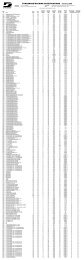
Model RPM Collet Style Muffler Insert Size<br />
48201 25,000 3 Piece Extended 1/4" & 6 mm<br />
48203 30,000 3 Piece Extended 1/4" & 6 mm<br />
48325 25,000 3 Piece Standard 1/4" & 6 mm<br />
48327 30,000 3 Piece Standard 1/4" & 6 mm<br />
48341 30,000 3 Piece Overhose 1/8" & 3 mm<br />
48345 30,000 4 Piece Standard 1/8" & 3 mm<br />
48350 35,000 3 Piece Extended 1/8" & 3 mm<br />
48355 35,000 3 Piece Extended 1/4" & 6 mm<br />
48360 20,000 3 Piece Standard 1/4" & 6 mm<br />
48365 20,000 4 Piece Standard 1/8" & 3 mm<br />
48370 25,000 4 Piece Standard 1/8" & 3 mm<br />
WARNING<br />
Read and understand tool manual before<br />
work starts to reduce risk of injury to<br />
operator, visitors, and tool.<br />
WARNING<br />
Eye protection must be worn<br />
at all times, eye protection to<br />
conform to ANSI Z87.1.<br />
WARNING<br />
Respiratory protection to be used when<br />
exposed to contaminants that exceed the<br />
applicable threshold limit values required by law.<br />
WARNING<br />
SAFETY LEGEND<br />
Parts Page Reorder No. PD12•03<br />
Effective January, 2012<br />
Supersedes PD11•26<br />
FIND THE MOST CURRENT OFFERING OF SUPPORT DOCUMENTS AND ACCESSORIES AT WWW.DYNABRADE.COM<br />
Read and understand this tool manual before operating your air tool. Follow all safety rules for the protection of operating personnel<br />
as well as adjacent areas. Always operate, inspect and maintain this tool in accordance with the American National Standards<br />
Institute (ANSI) Safety Code for Portable Air Tools – B186.1. For additional safety information, refer to Safety Requirements for the<br />
Use, Care and Protection of Abrasive Wheels – ANSI B7.1, Code of Federal Regulation – CFR 29 Part 1910, European Committee for<br />
Standards (EN) Hand Held Non-Electric Power Tools – Safety Requirements and applicable State and Local Regulations.<br />
WARNING<br />
Practice safety requirements. Work alert,<br />
have proper attire, and do not operate tools under<br />
the influence of alcohol or drugs.<br />
WARNING<br />
Ear protection to be worn when exposure to sound,<br />
exceeds the limits of applicable Federal, State or<br />
local statues, ordinances and/or regulations.<br />
WARNING<br />
Air line hazard, pressurized supply lines and flexible<br />
hoses can cause serious injury. Do not use damaged,<br />
frayed or deteriorated air hoses and fittings.<br />
WARNING<br />
Some dust created by sanding, grinding, drilling, and other construction activities contain chemicals known to cause cancer, birth defects<br />
or other reproductive harm. Some examples of these chemicals are:<br />
• Lead from lead-based paints<br />
• Crystalline silica from bricks and cement and other masonry products<br />
• Arsenic and chromium from chemically treated lumber<br />
Your risk from these exposures varies, depending on how often you do this type of work. To reduce your exposure to these chemicals: work in a well<br />
ventilated area, and work with approved safety equipment, such as those dust masks that are specially designed to filter out microscopic particles.<br />
SAFETY INSTRUCTIONS<br />
Carefully Read all instructions before operating or servicing any <strong>Dynabrade</strong> ® Abrasive Power Tool. Products offered by <strong>Dynabrade</strong> are not to be<br />
modified, converted or otherwise altered from the original design.<br />
Tool Intent: .4 <strong>hp</strong> <strong>Die</strong> <strong>Grinder</strong> is ideal for deburring, deflashing, surface preparation, cleaning and finishing using the proper abrasive stones, abrasive<br />
mounted wheels, molded abrasives, and carbide burrs.<br />
Do Not use tool for anything other than its intended applications.<br />
This power tool is not intended for use in potentially explosive atmospheres and is not insulated against contact with electrical power.<br />
Training: Proper care, maintenance, and storage of your air tools will maximize their performance.<br />
Employer's Responsibility – Provide .4 <strong>hp</strong> <strong>Die</strong> <strong>Grinder</strong> operators with safety instructions and training for safe use of tools and accessories.<br />
(continued on next page)<br />
For Serial No. 11L3552A and Higher<br />
Model 48327
SAFETY INSTRUCTIONS (Continued)<br />
Accessory Selection:<br />
Abrasive/accessory RPM (speed) rating MUST be approved for AT LEAST the tool RPM rating.<br />
Before mounting an accessory, visually inspect for defects. Do not use defective accessories.<br />
Use only accessories of the correct shaft size for the collet (example: 1/4" shaft = 1/4" collet).<br />
Use only recommended accessories. Reference <strong>Dynabrade</strong> catalog and this tool manual.<br />
Follow tool specifications before choosing size and type of accessory.<br />
Only use recommended fittings and air line sizes. Air supply hoses and air hose accessories must have a minimum working pressure of 150 PSIG<br />
(10 Bars) or 150 percent of the maximum pressure produced in the system, whichever is higher. (See tool Machine Specifications table.)<br />
OPERATING INSTRUCTIONS<br />
Warning: Always wear personal protective equipment. Operator of tool is responsible for following: accepted eye, face, respiratory, hearing and body protection.<br />
Caution: Hand, wrist and arm injury may result from repetitive work, motion and overexposure to vibration.<br />
Keep hand and clothing away from working end of the air tool.<br />
Working end of tool has a potential of cutting and severing.<br />
Operation: Be sure that any loose clothing, hair and all jewelry is properly restrained.<br />
Secure inlet bushing on air tool with a wrench before attempting to install the air fitting to avoid damaging housing assembly.<br />
BEFORE MOUNTING AN ACCESSORY, after all tool repairs and whenever a .4 <strong>hp</strong> <strong>Die</strong> <strong>Grinder</strong> is issued for use, check tool RPM (speed) with tachometer<br />
with air pressure set at 90 PSIG while the tool is running. If tool is operating at a higher speed than the RPM marked on the tool housing, or operating<br />
improperly, the tool must be serviced and corrected before use.<br />
Caution: Tool RPM must never exceed abrasive/accessory RPM rating. Check accessory manufacturer for details on maximum operating speed or special<br />
mounting instructions. Improper mounting of an accessory may cause excessive vibration levels or damage the accessory. Make sure no one is in the<br />
unguarded plane of the accessory. Run tool for 1 minute of operating speed in a protected area.<br />
Collet Body<br />
PROPER MOUNTING PROCEDURE<br />
With Power Source Disconnected from the Tool, Mount Recommended Accessory<br />
Collet Cap<br />
Collet Insert<br />
Excessive Overhang Reduces Bit MOS,<br />
Refer to ANSI B7.1 Standards<br />
Burr/Mounted Wheel<br />
Connect air tool to power source. Be careful NOT to depress throttle lever in the process. Do not expose air tool to inlet pressure above 90 PSIG or (6.2 Bars).<br />
Caution: After installing the accessory, before testing or use and/or after assembling tool, the .4 <strong>hp</strong> <strong>Die</strong> <strong>Grinder</strong> must be started at a reduced speed to check<br />
for good balance. Gradually increase tool speed. DO NOT USE if tool vibration is excessive. Correct cause, and retest to insure safe operation. Test tool at<br />
its free speed (RPM) in a protected area for at least one minute before applying the tool to the work.<br />
Release throttle lever when air supply is interrupted.<br />
Make sure that work area is uncluttered, and visitors are at a safe range from the tools and debris.<br />
Air tools are not intended for use in explosive atmospheres and are not insulated for contact with electric power sources.<br />
Use a vise or clamping device to hold work piece firmly in place.<br />
Do not apply excessive force on tool or apply “rough” treatment to it.<br />
Always work with a firm footing, posture and proper lighting.<br />
Ensure that sparks and debris resulting from work does not create a hazard.<br />
Tool is rear exhaust, exhaust may contain lubricants, vane material, bearing grease, and other materials flushed thru the tool.<br />
Warning: Grinding certain materials can create explosive dust. It is the employers responsibility to notify the user of acceptable dust levels.<br />
Grinding can cause sparks which can cause fires or explosions. It is the users responsibility to make sure the work area is free of flammable materials.<br />
DO NOT USE cut-off wheels or router bits on this tool.<br />
Always use dust extraction or suppression systems and personal protective equipment which are suitable for the materials being processed.<br />
Report to your supervisor any condition of the tool, accessories, or operation you consider unsafe.<br />
2<br />
Mount Wheel/Burr Mandrel<br />
Fully Inserted into Collet Insert.<br />
Note: Intended for general<br />
reference use only. Always refer<br />
to ANSI B7.1, B186.1 and EN<br />
792 for detailed requirements.<br />
Bit Gripping Length: Bit should be<br />
inserted no less than 1" (13mm) into<br />
the collet insert.
Filter<br />
Regulator<br />
90 PSIG<br />
(6.2 Bar)<br />
Lubricator<br />
<strong>Dynabrade</strong> Air Power Tools are designed to operate at<br />
90 PSIG (6.2 Bar) maximum air pressure at the tool inlet,<br />
when the tool is running. Use recommended regulator<br />
to control air pressure.<br />
Ideally the air supply should be free from moisture. To<br />
facilitate removing moisture from air supply, the installation<br />
of a refrigerated air dryer after the compressor and the use<br />
of drain valves at each tool station is recommended.<br />
Air System<br />
LUBRICATOR SETTING<br />
1 DROP/MIN.<br />
20 SCFM<br />
Closed Loop Pipe System<br />
(Sloped in the direction of air flow)<br />
To Tool Station<br />
Maintenance Instructions<br />
Important: To keep tool safe a Preventative Maintenance Program is recommended whenever portable power tools are used. The program should include<br />
inspection of air supply lines, air line pressure, proper lubrication and repair of tools. Refer to ANSI B186.1 for additional maintenance information.<br />
Use only genuine <strong>Dynabrade</strong> replacement parts to ensure quality. To order replacement parts, specify Model#, Serial# and RPM of your air tool.<br />
It is strongly recommended that all <strong>Dynabrade</strong> rotary vane air tools be used with a Filter-Regulator-Lubricator to minimize the possibility of misuse due to<br />
unclean air, wet air or insufficient lubrication. <strong>Dynabrade</strong> recommends the following: 10681 Air Line Filter-Regulator-Lubricator — Provides accurate air<br />
pressure regulation, two-stage filtration of water contaminants and micro-mist lubrication of pneumatic components. Delivers up to 55 SCFM/1,558 LPM<br />
@ 145 PSIG/9.7 Bar (Max. Air Temperature of 140˚F/60˚ C) Note: Two (2) 3/8" NPT Reducer Bushings are included.<br />
<strong>Dynabrade</strong> recommends one drop of air lube per minute for each 20 SCFM (example: if the tool specification states 40 SCFM, set the drip rate on the<br />
filter-lubricator to 2 drops per minute). <strong>Dynabrade</strong> Air Lube (P/N 95842: 1 pt 473 ml) is recommended.<br />
Specific Routine Preventative Maintenance - 20,000, 25,000 and 30,000 RPM Governed Tools: Check free speed tool using a tachometer without accessory<br />
mounted. This governor controlled die grinder should be speed checked every 20 hours of use or weekly, whichever occurs more frequently after maintenance or repair.<br />
DO NOT disassemble the governor for any reason. Reorder correct speed – governor assembly (See Assembly Breakdown) and recheck free speed of<br />
tool with a tachometer.<br />
Specific Routine Preventative Maintenance - 35,000 RPM Non-Governed Tools:<br />
Check free speed of tool regularly using a tachometer without the abrasive accessory mounted. After all tool repairs and whenever a .4 <strong>hp</strong> <strong>Die</strong> <strong>Grinder</strong> is<br />
issued for use, check tool RPM (speed) with tachometer with air pressure set at 90 PSIG while the tool is running. If tool is operating at a higher speed<br />
than the RPM marked on the tool housing, operating improperly or demonstrates unusual vibration, the tool must be serviced and corrected before use.<br />
Routine Preventative Maintenance<br />
Inspect accessories before mounting. Do not mount accessories that are damaged or nicked.<br />
Check accessory - speed rating. Rating on accessory must be greater than the tool speed marked on the housing.<br />
If accessory breakage occurs, investigate to determine the cause and correct before issuing tool for work.<br />
Mineral spirits are recommended when cleaning the tool and parts. Do not clean tool or parts with any solvents or oils containing acids, esters, ketones,<br />
chlorinated hydrocarbons or nitro carbons.<br />
DO NOT clean or maintain tools with chemicals that have a low flash point (example: WD-40 ® ).<br />
A Motor Tune-Up Kit (P/N 96541) is available which includes high wear and medium wear motor parts.<br />
Air tool markings must be kept legible at all times, if not, reorder housing and replace. User is responsible for maintaining specification information<br />
i.e.: Model #, S/N, and RPM. (See Assembly Breakdown)<br />
Blow air supply hose out prior to initial use.<br />
Visually inspect air hoses and fittings for frays, visible damage and signs of deterioration. Replace damaged or worn components.<br />
Refer to <strong>Dynabrade</strong>'s Warning/Safety Operating Instructions Tag (Reorder No. 95903) for safety information.<br />
After maintenance is performed on tool, add a few drops of <strong>Dynabrade</strong> Air Lube (P/N 95842) to the tool inlet and start the tool a few times to lubricate air motor.<br />
Check for tool vibration before mounting abrasive wheel accessory.<br />
Handling and Storage:<br />
Use of tool rests, hangers and/or balancers is recommended.<br />
Protect tool inlet from debris (see Notice on Page 7).<br />
DO NOT carry tool by air hose or near the tool throttle lever.<br />
Protect accessories from exposure to water, solvents, high humidity, freezing temperature and extreme temperature changes.<br />
DO NOT USE accessories that have been dropped or show signs of cracks, nicks or other defects.<br />
Store accessories in protective racks or compartments to prevent damage.<br />
3<br />
➤<br />
Drain<br />
Valve<br />
Ball<br />
Valve<br />
Filter<br />
Drain<br />
Valve<br />
Regulator<br />
90 PSIG MAX<br />
(6.2 Bar)<br />
Air Tool<br />
Lubricator<br />
➤<br />
➤<br />
Air Hose<br />
Drain Valve<br />
Ball<br />
Valve<br />
Air Flow<br />
➤ ➤<br />
Air Flow<br />
Air Compressor<br />
and Receiver<br />
Refrigerated<br />
Air Dryer<br />
➤
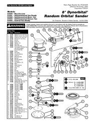
Models:<br />
48201, 48203, 48325, 48327<br />
48341, 48345, 48350, 48355<br />
48360, 48365, 48370<br />
1 01484 Collet Cap<br />
2 Collet Insert<br />
01495 1/8"<br />
01485 1/4"<br />
01496 3 mm<br />
01497 6 mm<br />
3 01435 Collet Body<br />
4 51098 Collet Nut<br />
5 51107 Collet Cap<br />
6 51105 Collet Body<br />
7 01489 Rear Exhaust Cover<br />
8 01547 Collar<br />
9 01580 Felt Seal<br />
10 02649 Bearing<br />
11 54551 Shim - 0.003"<br />
12 54543 Shim - 0.001"<br />
13 54544 Shim - 0.002"<br />
14 01478 Front End Plate<br />
15 50767 Pin (2)<br />
16 01479 Spacer<br />
17 01480 Vane Set (4/Pkg.) As Req.<br />
18 45290 Rotor<br />
19 01476 Cylinder<br />
20 02676 Rear Bearing Plate<br />
21 02696 Bearing<br />
22 96077 O-Ring<br />
23 Governor Assembly<br />
45270 20,000 RPM (Yellow)<br />
45271 25,000 RPM (Red)<br />
45272 30,000 RPM (Green)<br />
24 45320 Governor Chamber<br />
25 45305 Housing Core<br />
26 45315 Throttle Bushing<br />
27 97045 Pin<br />
28 45263 Safety Throttle Lever<br />
29 97060 Pin<br />
30 Exterior Housing (Laser Etched)<br />
45209 Model - 48201<br />
45210 Model - 48203<br />
45201 Model - 48325<br />
45202 Model - 48327<br />
45217 Model - 48341<br />
45218 Model - 48345<br />
45219 Model - 48350<br />
45220 Model - 48355<br />
45221 Model - 48360<br />
45231 Model - 48365<br />
09707 Model - 48370<br />
31 45310 Seal<br />
32 58365 Tip Valve<br />
33 01468 Spring<br />
34 01564 Air Control Ring<br />
35 95711 Retaining Ring<br />
36 01486 Felt Silencer (4)<br />
37 96065 O-Ring<br />
38 01446 Air Deflector<br />
39 95620 Retaining Ring<br />
40 01578 Inlet Adapter Assembly<br />
41 95438 O-Ring<br />
42 94521 Muffler Base<br />
43 94524 Sintered Bronze Muffler<br />
44 94525 Felt Muffler<br />
45 94522 Muffler Cap<br />
46 95375 O-Ring<br />
47 94526 Spacer<br />
48 94523 Inlet Adapter Assembly<br />
49 94535 Stanard Muffler Assembly<br />
50 94520 Extended Muffler Assembly<br />
3 - Piece Collet Assy.<br />
50080 1/4" Insert<br />
4 - Piece Collet Assy.<br />
Index Key<br />
51121 1/8" Insert<br />
No. Part # Description<br />
51124 1/4" Insert<br />
1<br />
3 - Piece Collet<br />
96076 12 mm Wrench<br />
95262 14 mm Wrench<br />
4 - Piece Collet<br />
96031 7/16" Wrench<br />
96032 11/16" Wrench<br />
22<br />
35<br />
LH<br />
41<br />
10<br />
23<br />
24<br />
42<br />
4<br />
11<br />
12<br />
25<br />
35<br />
43<br />
2<br />
13<br />
26<br />
.4 <strong>hp</strong> <strong>Die</strong> <strong>Grinder</strong><br />
Complete Assembly – All Models<br />
15<br />
Governors are Non-serviceable.<br />
Used on 20,000 - 30,000 RPM models ONLY.<br />
T<br />
A 10<br />
0.7 N m<br />
5<br />
A 8<br />
2<br />
14<br />
3<br />
36<br />
44<br />
4<br />
17<br />
16<br />
27<br />
6<br />
28<br />
45<br />
18<br />
37<br />
29<br />
A 8<br />
19<br />
T<br />
7<br />
38<br />
46<br />
O<br />
A<br />
T<br />
T<br />
28 N m<br />
30<br />
39<br />
47<br />
8<br />
20<br />
15<br />
1.7 - 2.3 N m<br />
31<br />
40<br />
9<br />
21<br />
48<br />
32<br />
A 8<br />
Oil: O 1 = Air Lube<br />
A 8<br />
33<br />
49<br />
50<br />
34<br />
28 N m<br />
KEY<br />
Adhesive: A8 = Loctite #567<br />
A10 = Loctite #243<br />
Torque: N m x 8.85 = In. - lbs.<br />
T<br />
T<br />
O 1<br />
O 1<br />
28 N m
Disassembly/Assembly Instructions<br />
Important: The <strong>Dynabrade</strong> Pneumatic Power Tool Lifetime Warranty Policy does NOT cover normally wearable parts and products. Before servicing this tool<br />
please contact <strong>Dynabrade</strong> <strong>Inc</strong>. or a <strong>Dynabrade</strong> Subsidiary for information regarding the <strong>Dynabrade</strong> Pneumatic Power Tool Lifetime Warranty Policy.<br />
Notice: To avoid damaging the motor housing, use the Special Repair Tool that is designed for disassembly and assembly of these die grinders.<br />
See page 8 for a complete list of available repair tools.<br />
Disconnect the die grinder from the air supply.<br />
Motor Disassembly:<br />
1. Secure the air inlet adapter of the die grinder in a vise with aluminum or bronze jaws so that the collet assembly is pointing up.<br />
2. Loosen the collet cap and remove the insert tool, cap and insert.<br />
3. Use the 50971 Lock Ring Tool to remove the rear exhaust cover. Turn counterclockwise.<br />
Note: One of two things will occur.<br />
A. The rear exhaust cover will loosen. If this occurs, remove the rear exhaust cover and remove the air motor assembly by pulling the motor out of the<br />
housing. Remove the filter cage and filter. Insert the hex end of the 96402 Special Repair Tool into the hex socket in the bottom of the housing.<br />
Use an adjustable wrench to loosen the housing from the air inlet adapter.<br />
96402 - Special Repair Tool<br />
“Tear-Drop End” Hex End<br />
B. The air inlet adapter will loosen. If this occurs, remove the air inlet adapter and valve components.<br />
Remove the 2 valve seals (Fig.1). Insert the “Tear-Drop End” of the 96402 Special Repair Tool into the air inlet of the housing. Place the hex end of the<br />
special repair tool in a vise with aluminum or bronze jaws so that the housing is pointing up (Fig.2 & 3). Use the 50971 Lock Ring Tool to remove the rear<br />
exhaust cover (Fig.4). Turn counterclockwise.<br />
1 2 3 4<br />
FOR MODELS WITH GOVERNORS: 48201, 48203, 48325, 48327, 48341, 48345, 48360, 48365 and 48370<br />
4. Carefully secure the wrench flats of the collet body in a vise with aluminum or bronze jaws so that the governor assembly is pointing up. Use a slot blade<br />
screwdriver to remove the governor. LEFT HAND THREAD: Turn clockwise. Note: The governor assembly is not serviceable. If a governor fails it must be<br />
replaced as a complete assembly.<br />
FOR ALL MODELS:<br />
5. Fasten the 96346 Bearing Separator (2") around the portion of the 01476 Cylinder that is closest to the 02673 Rear Bearing Plate. Place the bearing<br />
separator and the motor in the 96232 Arbor Press (#2) so that the collet body is pointing down.<br />
6. Use a 5/32" (4 mm) diameter flat end drive punch as a press tool to push the rotor out of the 02696 Bearing.<br />
7. Remove the cylinder and vanes.<br />
8. Use the 5/32" (4 mm) diameter flat end drive punch to push the 02696 Bearing out of the 02673 Rear Bearing Plate.<br />
9. Secure the body of the rotor in a vise with aluminum or bronze jaws and remove the 01435 Collet Body. Turn counterclockwise.<br />
10. Remove the 01478 Front Bearing Plate, 02649 Bearing, shims, and 01479 Spacer.<br />
Motor Disassembly Complete.<br />
Important: Clean and Inspect Parts for Wear or Damage Before Assembling.<br />
(continued on next page)<br />
5
1. Secure the body of the rotor in a vise with aluminum or bronze jaws and install the 01479 Spacer onto the rotor.<br />
2. Select .003" (.08 mm) shim thickness from the 54529 Shim Pack and install these into the 01478 Front Bearing Plate.<br />
3. Install the 02649 Bearing into the front bearing plate and install these onto the rotor.<br />
4. Install the 01435 Collet Body onto the 45290 Rotor. (Torque to 17 N m/150 in. lbs.)<br />
5. Use a .001" (0.3 mm) thick feeler gauge to check the clearance between the bearing plate and the face of the rotor.<br />
6. Clearance should be .001"-.0015" (0.3-0.4 mm). Note: If the clearance needs adjustment, repeat steps 2-6. Add or remove shims as required.<br />
7. Use <strong>Dynabrade</strong> Air Lube 95842 (10W/NR or equivalent) to lubricate the 01480 Vanes. Install the vanes into the rotor.<br />
8. Install the 01476 Cylinder and the 02673 Rear Bearing Plate so that the air inlet openings align with each other.<br />
9. Position the 02696 Bearing onto the bearing journal of the rotor.<br />
10. Use the RAISED CENTER of the 96242 Bearing Press Tool and the arbor press to install the 02696 Bearing onto the rotor and into the 02673 Rear<br />
Bearing Plate. IMPORTANT: Carefully press the bearing onto the rotor and into the plate until the plate just touches the cylinder. This will establish a snug<br />
fit between the bearing plates and the cylinder.<br />
FOR MODELS WITH GOVERNORS: 48201, 48203, 48325, 48327, 48341, 48345, 48360, 48365 and 48370<br />
11. Apply a small amount of the Loctite #243 (or equivalent) to the threads of the governor assembly and carefully install the governor onto the rotor.<br />
LEFT HAND THREAD: Turn counterclockwise. (Torque to 0.5 - 0.9 N m/5 - 8 in. lbs.)<br />
FOR ALL MODELS:<br />
12. Install the filter onto the filter cage, and install these into the housing.<br />
13. Carefully slide the motor assembly into the housing.<br />
14. Install the 01580 Felt Silencer onto the front of the air motor.<br />
15. Apply a small amount of Loctite #567 (or equivalent) to the threads of the rear exhaust cover and install the cover onto the housing. (Torque to 28<br />
N m/250 in. lbs.)<br />
Motor Assembly Complete. Tool Assembly Complete. Please allow 30 minutes for adhesives to cure before operating tool.<br />
Important: Before operating, place 2-3 drops of <strong>Dynabrade</strong> Air Lube (P/N 95842) directly into air inlet with throttle lever depressed. Operate tool for 30 seconds<br />
to determine if tool is operating properly and to allow lubricating oils to properly penetrate motor. Motor should now be tested for proper operation at 90 PSIG. If<br />
motor does not operate properly or operates at a higher RPM than marked on the tool, the tool should be serviced to correct the cause before use.<br />
Machine Specifications<br />
6<br />
Loctite ® is a registered trademark of Loctite Corp.<br />
Model Motor Motor Sound Maximum Air Flow Collet Air Pressure Weight Length Height<br />
Number <strong>hp</strong> (W) RPM Level SCFM (LPM) Insert Size PSIG (Bars) Pound (kg) <strong>Inc</strong>h (mm) <strong>Inc</strong>h (mm)<br />
48201 .4 (298) 25,000 76 dB(A) 23 (651) 1/4" & 6 mm 90 (6.2) .9 (.4) 8 (202) 1.7 (44)<br />
48203 .4 (298) 30,000 78 dB(A) 23 (651) 1/4" & 6 mm 90 (6.2) .9 (.4) 8 (202) 1.7 (44)<br />
48325 .4 (298) 25,000 79 dB(A) 23 (651) 1/4" & 6 mm 90 (6.2) .9 (.4) 8 (202) 1.7 (44)<br />
48327 .4 (298) 30,000 79 dB(A) 23 (651) 1/4" & 6 mm 90 (6.2) .9 (.4) 6.5 (166) 1.7 (44)<br />
48341 .4 (298) 30,000 79 dB(A) 23 (651) 1/8" & 3 mm 90 (6.2) .9 (.4) 6.5 (166) 1.7 (44)<br />
48345 .4 (298) 30,000 79 dB(A) 23 (651) 1/8" & 3 mm 90 (6.2) .9 (.4) 6.5 (166) 1.7 (44)<br />
48350 .4 (298) 35,000 80 dB(A) 23 (651) 1/8" & 3 mm 90 (6.2) .9 (.4) 8 (202) 1.7 (44)<br />
48355 .4 (298) 35,000 80 dB(A) 23 (651) 1/4" & 6 mm 90 (6.2) .9 (.4) 8 (202) 1.7 (44)<br />
48360 .4 (298) 20,000 76 dB(A) 23 (651) 1/4" & 6 mm 90 (6.2) .9 (.4) 6.4 (162) 1.7 (44)<br />
48365 .4 (298) 20,000 76 dB(A) 23 (651) 1/8" & 3 mm 90 (6.2) .9 (.4) 6.4 (162) 1.7 (44)<br />
48370 .4 (298) 25,000 79 dB(A) 23 (651) 1/8" & 3 mm 90 (6.2) .9 (.4) 6.4 (162) 1.7 (44)<br />
Additional Specifications: Air Inlet Thread 1/4" NPT Hose I.D. 1/4" (6 mm)<br />
Sound Level is the pressure measurement according to the method outlined in ISO regulation ISO-15744<br />
Lifetime Warranty<br />
All <strong>Dynabrade</strong> portable pneumatic power tools are rigorously inspected and performance tested in our factory before shipping to our<br />
customers. If a <strong>Dynabrade</strong> tool develops a performance problem and an inherent defect is found during normal use and service, <strong>Dynabrade</strong><br />
will warrant this tool against defects in workmanship and materials for the lifetime of the tool. Upon examination and review at our factory,<br />
<strong>Dynabrade</strong> shall confirm that the tool qualifies for warranty status, and will repair or replace the tool at no charge to the customer. Normally<br />
wearable parts and products are NOT covered under this warranty. Uncovered items include bearings, contact wheels, rotor blades, regulators,<br />
valve stems, levers, shrouds, guards, O-rings, seals, gaskets and other wearable parts. <strong>Dynabrade</strong>’s warranty policy is contingent upon proper<br />
use of our tools in accordance with factory recommendations, instructions and safety practices. It shall not apply to equipment that has been<br />
subjected to misuse, negligence, accident or tampering in any way so as to affect its normal performance. To activate lifetime warranty,<br />
customer must register each tool at www.dynabrade.com. <strong>Dynabrade</strong> will not honor lifetime warranty on unregistered tools. A one-year<br />
warranty will be honored on all unregistered portable pneumatic power tools. Lifetime warranty applies only to portable pneumatic tools<br />
manufactured by <strong>Dynabrade</strong>, <strong>Inc</strong>. in the USA. Lifetime warranty applies only to the original tool owner; warranty is non-transferable.
Preventative Maintenance Schedule<br />
.4 <strong>hp</strong> <strong>Die</strong> <strong>Grinder</strong> – All Models<br />
This service chart is published as a guide to expectant life of component parts. The replacement levels are based on average tool<br />
usage over one year. <strong>Dynabrade</strong> <strong>Inc</strong>. considers one year usage to be 1,000 hours.<br />
Parts Common to all Models:<br />
Index Part Description Number High Wear Medium Wear Low Wear Non-Wear<br />
# Number Required 100% 70% 30% 10%<br />
1 01484 Collet Cap 1 X<br />
2 See Note Collet Insert 1 X<br />
3 01435 Collet Body 1 X<br />
4 51098 Collet Nut 1 X<br />
5 51107 Collet Cap 1 X<br />
6 51105 Collet Body 1 X<br />
7 01489 Rear Exhaust Cover 1 X<br />
8 01547 Collar 1 X<br />
9 01580 Felt Seal 1 T, R<br />
10 02649 Bearing 1 T, R<br />
11 54551 Shim - .003" As Req. T, R<br />
12 54543 Shim - .001" As Req. T, R<br />
13 54544 Shim - .002" As Req. T, R<br />
14 01478 Front Bearing Plate 1 X<br />
15 50767 Pin 1 D<br />
16 01479 Spacer 1 T<br />
17 01480 Vane Set (4/Pkg.) As Req. T, R<br />
18 45290 Rotor 1 X<br />
19 01476 Cylinder 1 X<br />
20 02676 Rear Bearing Plate 1 X<br />
21 02696 Bearing 1 T, R<br />
22 96077 O-Ring 1 T<br />
23 See Note Governor Assembly 1 D<br />
24 45320 Governor Chamber 1 X<br />
25 45305 Housing Core 1 X<br />
26 45315 Throttle Bushing 1 T<br />
27 97045 Pin 1 T<br />
28 45263 Safety Throttle Lever 1 D<br />
29 97060 Pin 1 T<br />
30 See Note Exterior Housing 1 X<br />
31 45310 Seal 1 T<br />
32 58365 Tip Valve 1 T<br />
33 01468 Spring 1 T<br />
34 01564 Air Control Ring 1 L<br />
35 95711 Retaining Ring 1 T, R<br />
36 01486 Felt Silencer 1 T, R<br />
37 96065 O-Ring 1 T<br />
38 01446 Air Deflector 1 X<br />
39 95620 Retaining Ring 1 T<br />
40 01578 Inlet Adapter Assembly 1 X<br />
41 95438 O-Ring 1 T<br />
42 94521 Muffler Base 1 X<br />
43 94525 Felt Muffler 1 T, R<br />
44 94524 Sintered Bronze Muffler 1 T, R<br />
45 94522 Muffler Cap 1 X<br />
46 95375 O-Ring 1 T<br />
47 94526 Spacer 1 X<br />
48 94523 Inlet Adapter Assembly 1 X<br />
Note: Please refer to page 4 of tool manual for specific part number.<br />
7<br />
LEGEND<br />
T <strong>Inc</strong>luded in Tune-Up Kit<br />
X Type of wear, no other<br />
comments apply.<br />
L Easily lost. Care during<br />
assembly/disassembly.<br />
D Easily damaged during<br />
assembly/disassembly.<br />
R Replace each time tool is<br />
disassembled.<br />
Tune-Up Kit<br />
Part No. 96541<br />
Notice<br />
All <strong>Dynabrade</strong> motors use the highest quality parts and metals available and are machined to exacting tolerances. The failure of quality pneumatic<br />
motors can most often be traced to an unclean air supply or the lack of lubrication. Air pressure easily forces dirt or water contained in the air supply into<br />
motor bearings causing early failure. It often scores the cylinder walls and the rotor blades resulting in limited efficiency and power. Our warranty obligation<br />
is contingent upon proper use of our tools and cannot apply to equipment which has been subjected to misuse such as unclean air, wet air or a lack of<br />
lubrication during the use of this tool.
<strong>Dynabrade</strong> Air Lube<br />
• Formulated for pneumatic equipment.<br />
• Absorbs up to 10% of its weight in water.<br />
• Prevents rust and formation of sludge.<br />
• Keeps pneumatic tools operating longer<br />
with greater power and less down time.<br />
Part No. 95821: 4oz. (118 ml)<br />
Part No. 95842: 1pt. (473 ml)<br />
Part No. 95843: 1gal. (3.8 L)<br />
Optional Accessories<br />
FIND THE MOST CURRENT OFFERING OF SUPPORT DOCUMENTS AND ACCESSORIES AT WWW.DYNABRADE.COM<br />
Lock Ring Wrench<br />
• Has a 3/8" square socket for use with<br />
3/8" drive; breaker bar, ratchet head, or<br />
torque wrenches.<br />
Part No. 50971<br />
Press Tool<br />
• Used to install bearings.<br />
Part No. 96242<br />
Bearing Separator<br />
• Use the separator to remove<br />
gears and bearings.<br />
Part No. 96346<br />
Male Plug<br />
• Provides up to twice the air flow<br />
compared to standard plug design.<br />
• Plug has “ported” design to prevent<br />
“starving” of the air tool.<br />
Part No. 95675<br />
Reference Contact Information<br />
1. American National Standards Institute – ANSI 3. European Committee for Standardization<br />
25 West 43rd Street Rue de Stassart 36<br />
Forth Floor<br />
New York, NY 10036<br />
Tel: 1 (212) 642-4900<br />
Fax: 1 (212) 398-0023<br />
B - 1050 Brussels, Belgium<br />
2. Government Printing Office – GPO 4. Power Tool Institute, <strong>Inc</strong>.<br />
Superintendent of Documents P.O. Box 818<br />
Attn. New Orders Yachata, Oregon 97498-0818<br />
P.O. Box 371954 Tel: 1 (503) 547-3185<br />
Pittsburgh, PA 15250-7954<br />
Tel: 1 (202) 512-1803<br />
Fax: 1 (503) 547-3539<br />
Visit Our Web Site: www.dynabrade.com Email: Customer.Service@<strong>Dynabrade</strong>.com<br />
Motor Tune-Up Kit<br />
• <strong>Inc</strong>ludes assorted parts to help<br />
maintain and repair motor.<br />
Part No. 96541<br />
Drop-In Motor<br />
• Allows quick and easy replacement.<br />
• No motor adjustments needed.<br />
Part No. 45286 – Models: 48201<br />
48203, 48325<br />
48327, 48341<br />
48350, 48355<br />
48360<br />
Part No. 45288 – Model: 48345<br />
48365, 48370<br />
Composite-Style Coupler<br />
• Lightweight 1.4 oz. (.05 Kg), non-marring<br />
composite material.<br />
• Easy connect/disconnect by single<br />
push-button action.<br />
• Shock-proof, low-vibration, crush-resistant.<br />
Part No. 94960 – 1/4" Female NPT<br />
Part No. 94980 – 1/4" Male NPT<br />
DYNABRADE ®<br />
DYNABRADE, INC., 8989 Sheridan Drive Clarence, NY 14031-1419 Phone: (716) 631-0100 Fax: 716-631-2073 International Fax: 716-631-2524<br />
DYNABRADE EUROPE S.àr.l., Zone Artisanale L-5485 Wormeldange—Haut, Luxembourg Telephone: 352 76 84 94 1 Fax: 352 76 84 95 1<br />
© DYNABRADE, INC., 2012 PRINTED IN USA PD12.03_01/12