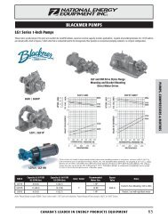
BLACKMER POWER PUMPS - National Energy Equipment
BLACKMER POWER PUMPS - National Energy Equipment
BLACKMER POWER PUMPS - National Energy Equipment

You also want an ePaper? Increase the reach of your titles
YUMPU automatically turns print PDFs into web optimized ePapers that Google loves.
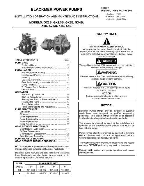
<strong>BLACKMER</strong> <strong>POWER</strong> <strong>PUMPS</strong><br />
INSTALLATION OPERATION AND MAINTENANCE INSTRUCTIONS<br />
MODELS: GX2B, GX2.5B, GX3E, GX4B,<br />
X2B, X2.5B, X3E, X4B<br />
TABLE OF CONTENTS Page<br />
PUMP DATA<br />
Technical Data .................................................... 2<br />
Initial Pump Start Up Information......................... 2<br />
INSTALLATION<br />
Pre-Installation Cleaning ..................................... 3<br />
Location and Piping............................................. 3<br />
Mounting ............................................................. 3<br />
Coupling Alignment ............................................. 4<br />
Gear Reducer Alignment – GX Models ............... 4<br />
Pump Rotation..................................................... 4<br />
To Change Pump Rotation.................................. 4<br />
Check Valves ...................................................... 4<br />
OPERATION<br />
Pre-Start Up Check List....................................... 5<br />
Start Up Procedures............................................ 5<br />
Running the Pump in Reverse Rotation .............. 6<br />
Flushing the Pump .............................................. 6<br />
Pump Relief Valve............................................... 6<br />
Relief Valve Setting and Adjustment ................... 6<br />
PUMP MAINTENANCE<br />
Lubrication.............................................................. 7<br />
Strainers................................................................. 7<br />
Vane Replacement................................................. 8<br />
Pump Disassembly ................................................ 8<br />
Parts Replacement................................................. 8<br />
Pump Assembly ..................................................... 9<br />
GEAR REDUCER MAINTENANCE<br />
Gear Reducer Lubrication .................................... 11<br />
Oil Seal Replacement .......................................... 12<br />
Gear Reducer Disassembly ................................. 12<br />
Gear Reducer Assembly ...................................... 12<br />
PUMP TROUBLE SHOOTING .................................... 13<br />
GEAR REDUCER TROUBLE SHOOTING.................. 14<br />
NOTE: Numbers in parentheses following individual parts<br />
indicate reference numbers on Blackmer Parts Lists.<br />
Blackmer pump manuals and parts lists may be obtained<br />
from Blackmer's website (www.blackmer.com) or by<br />
contacting Blackmer Customer Service.<br />
PUMP PUMP PARTS LIST<br />
MODEL 2” 2.5” 3” 4”<br />
GX 101-B01 101-B02 101-B03 101-B04<br />
X 101-B05 101-B06 101-B07 101-B08<br />
961222<br />
INSTRUCTIONS NO. 101-B00<br />
Section<br />
Effective<br />
Replaces<br />
SAFETY DATA<br />
101<br />
Oct 2007<br />
Aug 2007<br />
This is a SAFETY ALERT SYMBOL.<br />
When you see this symbol on the product, or in the<br />
manual, look for one of the following signal words and be<br />
alert to the potential for personal injury, death or major<br />
property damage<br />
Warns of hazards that WILL cause serious personal injury,<br />
death or major property damage.<br />
Warns of hazards that CAN cause serious personal injury,<br />
death or major property damage.<br />
Warns of hazards that CAN cause personal injury<br />
or property damage.<br />
NOTICE:<br />
Indicates special instructions which are very<br />
important and must be followed.<br />
NOTICE:<br />
Blackmer Pumps MUST only be installed in systems,<br />
which have been designed by qualified engineering<br />
personnel. The system MUST conform to all applicable<br />
local and national regulations and safety standards.<br />
This manual is intended to assist in the installation and<br />
operation of the Blackmer power pumps, and MUST be<br />
kept with the pump.<br />
Pump service shall be performed by qualified technicians<br />
ONLY. Service shall conform to all applicable local and<br />
national regulations and safety standards.<br />
Thoroughly review this manual, all instructions and hazard<br />
warnings, BEFORE performing any work on the pump.<br />
Maintain ALL system and pump operation and hazard<br />
warning decals.
Hazardous<br />
machinery can<br />
cause serious<br />
personal injury.<br />
Hazardous or toxic<br />
fluids can cause<br />
serious injury.<br />
Do not operate<br />
without guard<br />
in place<br />
Failure to disconnect and lockout<br />
electrical power or engine drive before<br />
attempting maintenance can cause<br />
severe personal injury or death<br />
If pumping hazardous or toxic fluids,<br />
system must be flushed and<br />
decontaminated, inside and out, prior to<br />
performing service or maintenance<br />
Operation without guards in place can<br />
cause serious personal injury, major<br />
property damage, or death.<br />
SAFETY DATA<br />
PUMP DATA<br />
Hazardous voltage.<br />
Can shock, burn or<br />
cause death.<br />
Hazardous pressure<br />
can cause personal<br />
injury or property<br />
damage<br />
Hazardous pressure<br />
can cause personal<br />
injury or property<br />
damage<br />
101-B00 page 2/16<br />
Failure to disconnect and lockout<br />
electrical power before attempting<br />
maintenance can cause shock, burns or<br />
death<br />
Disconnecting fluid or pressure<br />
containment components during pump<br />
operation can cause serious personal<br />
injury, death or major property damage<br />
Failure to relieve system pressure prior<br />
to performing pump service or<br />
maintenance can cause personal injury<br />
or property damage.<br />
PUMP IDENTIFICATION<br />
A pump Identification tag, containing the pump serial number, I.D. number, and model designation, is attached to each pump. It is<br />
recommended that the data from this tag be recorded and filed for future reference. If replacement parts are needed, or if<br />
information pertaining to the pump is required, this data must be furnished to a Blackmer representative.<br />
TECHNICAL DATA<br />
2”, 2.5” 3”, 4"<br />
Maximum Pump Speed 780RPM 640 RPM<br />
Maximum Viscosity 20,000 SSU (4,250 cP)<br />
Maximum Operating<br />
240 – 300°F (115 – 149°C)<br />
Temperature *<br />
Maximum Differential<br />
125 psi (8.6 Bar)<br />
Pressure<br />
Maximum Working<br />
175 psi (12.1 Bar)<br />
Pressure<br />
* Maximum operating limits are dependent on the materials of<br />
construction. See Blackmer Material Specs 101-095.<br />
INITIAL PUMP START UP INFORMATION<br />
Model No.: ____________________________________<br />
Serial No.: ____________________________________<br />
ID No.: _______________________________________<br />
Date of Installation: _____________________________<br />
Inlet Gauge Reading: ____________________________<br />
Discharge Gauge Reading: _______________________<br />
Flow Rate: _____________________________________
NOTICE:<br />
Blackmer pumps must only be installed in systems<br />
designed by qualified engineering personnel. System<br />
design must conform with all applicable regulations and<br />
codes and provide warning of all system hazards.<br />
Hazardous voltage.<br />
Can shock, burn or<br />
cause death.<br />
Install, ground and wire to local and<br />
<strong>National</strong> Electrical Code requirements.<br />
Install an all-leg disconnect switch near<br />
the unit motor.<br />
Disconnect and lockout electrical power<br />
before installation or service<br />
Electrical supply MUST match motor<br />
nameplate specifications.<br />
Motors equipped with thermal protection automatically<br />
disconnect motor electrical circuit when overload exists.<br />
Motor can start unexpectedly and without warning.<br />
PRE-INSTALLATION CLEANING<br />
NOTICE:<br />
New pumps contain residual test fluid and rust inhibitor.<br />
If necessary, flush pump prior to use.<br />
Foreign matter entering the pump WILL cause extensive<br />
damage. The supply tank and intake piping MUST be<br />
cleaned and flushed prior to pump installation and operation.<br />
LOCATION AND PIPING<br />
Pump life and performance can be significantly reduced when<br />
installed in an improperly designed system. Before starting<br />
the layout and installation of the piping system, review the<br />
following:<br />
1. Locate the pump as near as possible to the source of<br />
supply to avoid excessive inlet pipe friction.<br />
2. The inlet line MUST be at least as large as the intake<br />
port on the pump. The inlet piping should slope<br />
downward to the pump without any upward loops.<br />
Eliminate restrictions such as sharp bends; globe valves,<br />
unnecessary elbows, and undersized strainers.<br />
3. It is recommended a strainer be installed in the inlet line<br />
to protect the pump from foreign matter. The strainer<br />
should be located at least 24" (0.6m) from the pump, and<br />
have a net open area of at least four times the area of<br />
the intake piping. For viscosities greater than 1000 SSU,<br />
consult the strainer manufacture instructions. Strainers<br />
must be cleaned regularly to avoid pump starvation.<br />
4. The intake system must be free of air leaks.<br />
5. Expansion joints, placed at least 36" (0.9m) from the<br />
pump, will compensate for expansion and contraction of<br />
the pipes. Contact the flexible connector/hose<br />
manufacturer for required maintenance/care and design<br />
assistance in their use.<br />
6. Install pressure gauges in the NPT ports provided in the<br />
pump casing to check pump at start up.<br />
INSTALLATION<br />
101-B00 page 3/16<br />
7. ALL piping and fittings MUST be properly supported to<br />
prevent any piping loads from being placed on the pump.<br />
8. Check alignment of pipes to pump to avoid strains which<br />
might later cause misalignment. See Figure 1. Unbolt<br />
flanges or break union joints. Pipes should not spring<br />
away or drop down. After pump has been in operation<br />
for a week or two, completely recheck alignment.<br />
Figure 1<br />
9. When pumping liquids at elevated temperature,<br />
provisions should be made to compensate for expansion<br />
and contraction of the pipes, especially when long pipe<br />
lines are necessary. Steel pipe expands approximately<br />
3/4” (1.9 cm) per 100 feet (30.49 m) per 100°F (37.8°C)<br />
rise in temperature.<br />
PUMP MOUNTING<br />
A solid foundation reduces noise and vibration, and will<br />
improve pump performance. On permanent installations it is<br />
recommended the pumping unit be secured by anchor bolts<br />
as shown in Figure 2. This arrangement allows for slight<br />
shifting of position to accommodate alignment with the<br />
mounting holes in the base plate.<br />
Figure 2 - Pipe Type Anchor Bolt Box<br />
For new foundations, it is suggested that the anchor bolts be<br />
set in concrete. When pumps are to be located on existing<br />
concrete floors, holes should be drilled into the concrete to<br />
hold the anchor bolts.<br />
When installing units built on channel or structural steel type<br />
bases, use care to avoid twisting the base out of shape when<br />
anchor bolts are tightened. Shims should be used under the<br />
edges of the base prior to tightening of the anchor bolts to<br />
prevent distortion.
COUPLING ALIGNMENT<br />
The pump must be directly coupled to a gear and/or driver<br />
with a flexible coupling. Verify coupling alignment after<br />
installation of new or rebuilt pumps. Both angular and<br />
parallel coupling alignment MUST be maintained between the<br />
pump, gear, motor, etc. in accordance with manufacturer’s<br />
instructions. See Figure 3.<br />
1. Parallel alignment: The use of a laser alignment tool or<br />
dial indicator is preferred. If a laser alignment tool or dial<br />
indicator is not available, use a straightedge. Turn both<br />
shafts by hand, checking the reading through one<br />
complete revolution. Maximum offset should be less<br />
than .005" (.127 mm).<br />
2. Angular alignment: Insert a feeler gauge between the<br />
coupling halves. Check the spacing at 90° increments<br />
around the coupling (four checkpoints). Maximum<br />
variation should not exceed .005" (.127 mm). Some<br />
laser alignment tools will check angular alignment as<br />
well.<br />
3. Replace the coupling guards after setting alignment.<br />
Do not operate<br />
without guard<br />
in place<br />
Figure 3 – Alignment Check<br />
Operation without guards in place can<br />
cause serious personal injury, major<br />
property damage, or death.<br />
GEAR REDUCER ALIGNMENT – GX MODELS<br />
The reducer can be rotated on its mounting to raise or lower<br />
the input shaft to facilitate alignment to the motor shaft. To do<br />
so, first loosen the four clamp capscrews (20C) and the two<br />
setscrews (33) in the gear reducer spool flange. The reducer<br />
is then free to rotate. If necessary, tap it lightly with a soft<br />
faced mallet. When aligning the reducer, verify the alignment<br />
of the coupling halves as indicated in “Coupling Alignment”<br />
section.<br />
NOTICE:<br />
To determine maximum variation of gear reducer shaft<br />
alignment, refer to Blackmer GX model dimension pages<br />
101-B00 Page 4/16<br />
PUMP ROTATION<br />
A right-hand pump rotates clockwise with the intake and relief<br />
valve on the right side, when viewed from the driven end.<br />
A left-hand pump rotates counterclockwise with the intake<br />
and relief valve on the left side, when viewed from the driven<br />
end.<br />
NOTICE:<br />
On GX models, the gear reducer input shaft will rotate in<br />
the opposite direction of the pump shaft. For example,<br />
on a right-hand GX pump, the gear reducer shaft will<br />
rotate counterclockwise.<br />
NOTICE:<br />
Confirm correct pump rotation by checking the pump<br />
rotation arrows respective to pump driver rotation.<br />
TO CHANGE PUMP ROTATION<br />
To reverse rotation, the pump must be disassembled then<br />
reassembled with the shaft on the opposite side of the pump.<br />
See the ‘Maintenance’ section for instructions.<br />
CHECK VALVES<br />
The use of check valves or foot valves in the supply tank is<br />
not recommended with self-priming, positive displacement<br />
pumps.<br />
If the possibility of liquid backflow exists when the pump is<br />
off, a check valve in the pump discharge piping is<br />
recommended because the pump can motor in the reverse<br />
rotation and create undue stress on all attached components.<br />
Never start a pump when it is rotating in the reverse rotation<br />
as the added starting torque can damage the pump and<br />
related equipment.
Do not operate<br />
without guard<br />
in place<br />
Hazardous pressure<br />
can cause personal<br />
injury or property<br />
damage<br />
Operation without guards in place can<br />
cause serious personal injury, major<br />
property damage, or death.<br />
Disconnecting fluid or pressure<br />
containment components during pump<br />
operation can cause serious personal<br />
injury, death or major property damage<br />
PRE-START UP CHECK LIST<br />
1. Check the alignment of the pipes to the pump. Pipes<br />
should be supported so that they do not spring away or<br />
drop down when pump flanges or union joints are<br />
disconnected.<br />
2. Verify proper coupling alignment.<br />
3. On GX models, check the oil level in the gear reducer.<br />
Refer to ‘Lubrication’ in the ‘Gear Reducer Maintenance’<br />
section of this manual.<br />
NOTICE:<br />
Blackmer gear reducers are not lubricated at the factory.<br />
Oil MUST be added before initial pump start-up<br />
4. On GX models shipped without the gear reducer<br />
attached, grease the inboard bearing (where the gear<br />
reducer attaches to the pump head) See “Pump<br />
Lubrication” in the Maintenance section of this manual.<br />
5. Check the entire pumping system to verify that the proper<br />
inlet and discharge valves are fully open, and that the<br />
drain valves and other auxiliary valves are closed.<br />
6. Install vacuum and pressure gauges on the pump in the<br />
1/4” NPT connections provided to check suction and<br />
discharge conditions after pump start-up.<br />
7. Check the wiring of the motor, and briefly turn on the<br />
power to make sure that the pump rotates in the direction<br />
of the rotation arrow.<br />
OPERATION<br />
101-B00 Page 5/16<br />
Hazardous pressure<br />
can cause personal<br />
injury or property<br />
damage<br />
Hazardous pressure<br />
can cause personal<br />
injury or property<br />
damage<br />
Failure to relieve system pressure prior<br />
to performing pump service or<br />
maintenance can cause personal injury<br />
or property damage.<br />
Pumps operating against a closed valve<br />
can cause system failure, personal<br />
injury and property damage<br />
START UP PROCEDURES<br />
NOTICE:<br />
Consult the "General Pump Troubleshooting" section of<br />
this manual if difficulties during start up are<br />
experienced.<br />
1. Start the motor. Priming should occur within one minute.<br />
2. Check the suction and discharge pressure to see if the<br />
pump is operating within the expected conditions. Record<br />
pressures in the ‘Initial Start Up Information’ section.<br />
3. Check for leakage from the piping and equipment.<br />
4. Check for overheating, excessive noise or vibration of the<br />
pump, reducer, and motor.<br />
5. Check the flow rate to ensure the pump is operating<br />
within the expected parameters. Record flow rate in the<br />
‘Initial Start Up Information’ section.<br />
6. Check the pressure setting of the relief valve by briefly<br />
closing a valve in the discharge line and reading the<br />
pressure gauge. This pressure should be 20 psi (1.4 bar)<br />
higher than the maximum operating pressure.<br />
Do not run the pump for more than 15 seconds with<br />
the discharge valve completely closed.<br />
If adjustments need to be made, refer to "Relief Valve<br />
Setting & Adjustment."<br />
Hazardous pressure<br />
can cause personal<br />
injury or property<br />
damage<br />
Incorrect settings of the pressure relief<br />
valve can cause pump component<br />
failure, personal injury, and property<br />
damage.
RUNNING THE PUMP IN REVERSE ROTATION<br />
NOTICE:<br />
Pump should be operated in reverse rotation for no more<br />
than 10 minutes and only when a separate pressure<br />
relief valve is installed to protect the pump from<br />
excessive pressure.<br />
It may be desirable to run the pump in reverse rotation for<br />
system maintenance. The pump will operate satisfactorily in<br />
reverse rotation for a LIMITED time, at a reduced<br />
performance level.<br />
FLUSHING THE PUMP<br />
NOTICE:<br />
If flushing fluid is to be left in the pump for an extended<br />
time, it must be a lubricating, non-corrosive fluid. If a<br />
corrosive or non-lubricating fluid is used, it must be<br />
flushed from the pump immediately.<br />
1. To flush the pump, run the pump with the discharge<br />
valve open and the intake valve closed. Bleed air into<br />
the pump through the intake gauge plug hole or through<br />
a larger auxiliary fitting in the intake piping. Pump air for<br />
30 second intervals to clean out most of the pumpage.<br />
2. Run a system compatible flushing fluid through the pump<br />
for one minute to clear out the remainder of the original<br />
pumpage.<br />
3. To remove the flushing fluid, follow step 1 above.<br />
NOTICE:<br />
After flushing the pump some residual fluid will remain<br />
in the pump and piping.<br />
NOTICE:<br />
Properly dispose of all waste fluids in accordance with<br />
the appropriate codes and regulations.<br />
PUMP RELIEF VALVE<br />
NOTICE:<br />
The pump internal relief valve is designed to protect the<br />
pump from excessive pressure and must not be used as<br />
a system pressure control valve.<br />
X and GX series pumps are fitted with an internal pressure<br />
relief valve that bypasses back to the suction side of the<br />
pump.<br />
Pumping volatile liquids under suction lift may cause<br />
cavitation. Partial closing of the discharge valve WILL result<br />
in internal relief valve chatter and is NOT recommended. For<br />
these applications, install an external system pressure control<br />
valve, and any necessary bypass piping, back to the storage<br />
tank.<br />
A system pressure control valve is also recommended when<br />
operating for extended periods (more than 1 minute) against<br />
a closed discharge valve.<br />
101-B00 Page 6/16<br />
RELIEF VALVE SETTING AND<br />
ADJUSTMENT<br />
The relief valve pressure setting is marked on a metal tag<br />
attached to the valve cover. Generally, the relief valve should<br />
be set at least 15 - 20 psi (1.0 - 1.4 Bar) higher than the<br />
operating pressure, or the external bypass valve setting (if<br />
equipped).<br />
Hazardous pressure<br />
can cause personal<br />
injury or property<br />
damage<br />
Hazardous or toxic<br />
fluids can cause<br />
serious injury.<br />
Incorrect settings of the pressure relief<br />
valve can cause pump component<br />
failure, personal injury, and property<br />
damage.<br />
Relief valve cap is exposed to pumpage<br />
and will contain some fluid<br />
DO NOT remove the R /V Cap OR adjust the relief valve<br />
pressure setting while the pump is in operation.<br />
1. To INCREASE the pressure setting, remove the relief<br />
valve cap (1) and gasket (88). Loosen the locknut(3), if<br />
equipped. Turn the adjusting screw (2) inward, or<br />
clockwise. Inspect the R/V cap gasket (88) and replace<br />
as required. Reattach the R/V cap gasket and cap.<br />
2. To DECREASE the pressure setting, remove the relief<br />
valve cap (1) and gasket (88). Loosen the locknut(3), if<br />
equipped. Turn the adjusting screw (2) outward, or<br />
counterclockwise. Inspect the R/V cap gasket (88) and<br />
replace as required. Reattach the R/V cap gasket and<br />
cap.<br />
Refer to the individual Blackmer pump parts lists for various<br />
spring pressure ranges. Unless specified otherwise, pumps<br />
are supplied from the factory with the relief valve adjusted to<br />
the mid-point of the spring range.
Hazardous<br />
machinery can<br />
cause serious<br />
personal injury.<br />
Hazardous voltage.<br />
Can shock, burn or<br />
cause death.<br />
Hazardous pressure<br />
can cause personal<br />
injury or property<br />
damage<br />
Hazardous pressure<br />
can cause personal<br />
injury or property<br />
damage<br />
Hazardous or toxic<br />
fluids can cause<br />
serious injury.<br />
Do not operate<br />
without guard<br />
in place<br />
Failure to disconnect and lockout<br />
electrical power or engine drive<br />
before attempting maintenance can<br />
cause severe personal injury or death<br />
Failure to disconnect and lockout<br />
electrical power before attempting<br />
maintenance can cause shock, burns<br />
or death<br />
Failure to relieve system pressure<br />
prior to performing pump service or<br />
maintenance can cause personal<br />
injury or property damage.<br />
Disconnecting fluid or pressure<br />
containment components during pump<br />
operation can cause serious personal<br />
injury, death or major property damage<br />
If pumping hazardous or toxic fluids,<br />
system must be flushed and<br />
decontaminated, inside and out, prior<br />
to performing service or maintenance<br />
Operation without guards in place can<br />
cause serious personal injury, major<br />
property damage, or death.<br />
MAINTENANCE:<br />
101-B00 Page 7/16<br />
NOTICE:<br />
Maintenance shall be performed by qualified technicians<br />
only. Follow the appropriate procedures and warnings<br />
as presented in this manual.<br />
SCHEDULED MAINTENANCE<br />
LUBRICATION<br />
NOTICE:<br />
To avoid possible entanglement in moving parts do not<br />
lubricate pump bearings, gear reducer or any other parts<br />
while the pump is running.<br />
Pump bearings should be lubricated every three months at<br />
minimum. More frequent lubrication may be required,<br />
depending on the application and operating conditions.<br />
Recommended Grease:<br />
Exxon® - RONNEX MP Grease,<br />
Mobile® - MOBILITH AW-2 (64353-6) Grease, or<br />
equivalent Lithium grease..<br />
Greasing Procedure:<br />
1. Remove the grease relief fittings (76A) from the bearing<br />
covers (27, 27A).<br />
2. SLOWLY apply grease with a hand gun until grease<br />
begins to escape from the grease relief fitting port. (76)<br />
3. Replace the grease relief fittings (76A).<br />
DO NOT overgrease pump bearings. While it is normal for<br />
some grease to escape from the grease tell-tale hole after<br />
lubrication, excessive grease on pumps equipped with<br />
mechanical seals can cause seal failure.<br />
If equipped with a Blackmer gear reducer, refer to the ‘Gear<br />
Reducer Lubrication’ section of this manual.<br />
STRAINERS<br />
Strainers must be cleaned regularly to avoid pump starvation.<br />
Schedule will depend upon the application and conditions.
VANE REPLACEMENT<br />
NOTICE:<br />
Maintenance shall be performed by qualified technicians<br />
only. Follow the appropriate procedures and warnings<br />
as presented in manual.<br />
1. Flush the pump per instructions in this manual. Drain and<br />
relieve pressure from the pump and system as required.<br />
2. Remove the head assembly from the outboard<br />
(nondriven) side of the pump according to steps 5 - 8 in<br />
the "Pump Disassembly" section of this manual.<br />
3. Turn the shaft by hand until a vane comes to the top (12<br />
o'clock) position of the rotor. Remove the vane.<br />
4. Install a new vane, ensuring that the rounded edge is UP,<br />
and the relief grooves are facing towards the direction of<br />
rotation. See Figure 4.<br />
5. Repeat steps 3 and 4 until all vanes have been replaced.<br />
6. Reassemble the pump according to the "Pump<br />
Assembly." section of this manual.<br />
Figure 4 – Vane Replacement<br />
PUMP DISASSEMBLY<br />
NOTICE:<br />
Follow all hazard warnings and instructions provided in<br />
the “Pump Maintenance” section of this manual.<br />
1. Flush the pump per instructions in this manual. Drain and<br />
relieve pressure from the pump and system as required.<br />
2. On GX model pumps, disengage the motor shaft<br />
coupling and remove the four clamp capscrews (20C) to<br />
release the clamps (20B). Loosen the two setscrews (33)<br />
in the gear reducer spool flange. The gear reducer can<br />
then be rotated away from the motor shaft and lifted off<br />
the pump. Refer to “Gear Reducer Maintenance” for<br />
reducer disassembly instructions.<br />
3. Starting on the inboard (driven) end of the pump, clean<br />
the pump shaft thoroughly, making sure the shaft is free<br />
of nicks and burrs. This will prevent damage to the<br />
mechanical seal when the inboard head assembly is<br />
removed.<br />
4. On X model pumps, remove the inboard bearing cover<br />
capscrews (28) and slide the inboard bearing cover (27A)<br />
and gasket (26) off the shaft. Discard the gasket. On the<br />
X2 and X2.5-inch pump models, the dirt shield will come<br />
off with the bearing cover. Inspect dirt shield and replace<br />
as required.<br />
101-B00 Page 8/16<br />
5. Remove the outboard bearing cover capscrews (28) and<br />
the outboard bearing cover (27) and bearing cover gasket<br />
(26). Discard the bearing cover gasket.<br />
6. The X2.5 and X3 pump models only are equipped with<br />
locknuts (24A) and lockwashers (24B). To remove:<br />
a. Bend up the engaged lockwasher tang and rotate the<br />
locknut counterclockwise to remove it from the shaft.<br />
b. Slide the lockwasher off the shaft. Inspect the<br />
lockwasher for damage and replace as required.<br />
c. Repeat steps a and b on the opposite shaft end.<br />
7. Remove the head capscrews (21). Gently pry the head<br />
away from the cylinder.<br />
8. Slide the head off the shaft. The head O-ring (72),<br />
bearing (24), and mechanical seal (153) will come off with<br />
the head assembly. Remove and discard the head O-ring.<br />
a. Pull the bearing (24) from the housing in the head.<br />
b. To remove the mechanical seal, use two screw<br />
drivers against the backside of the seal jacket to<br />
gently push the seal from the head (see Figure 5.<br />
Use care when placing the screw drivers to prevent<br />
damage to the seal faces. Remove and discard the<br />
seal O-rings.<br />
Figure 5 – Mechanical Seal Removal<br />
9. Pull the rotor and shaft (13) from the cylinder. While one<br />
hand is pulling the shaft, the other hand should be<br />
cupped underneath the rotor to prevent the vanes (14)<br />
and push rods (77) from falling out. Carefully set the rotor<br />
and shaft aside for future vane replacement and<br />
reassembly.<br />
10. Remove the remaining components from the outboard<br />
side of the pump, as instructed in steps 7 and 8 above.<br />
PARTS REPLACEMENT<br />
1. If any of the O-rings have been removed or disturbed<br />
during disassembly, they be replaced with new O-rings.<br />
NOTE: PTFE O-rings should be heated in hot water to aid<br />
installation.<br />
2. Excessive or continuous leakage from the tell-tale hole in<br />
the bearing cover may be an indication of a damaged<br />
mechanical seal. If a mechanical seal has been leaking, it<br />
is recommended the entire seal be replaced. Refer to<br />
"General Pump Troubleshooting" for possible causes of<br />
seal leakage.
PUMP ASSEMBLY<br />
Before reassembling the pump, inspect all component<br />
parts for wear or damage, and replace as required. Wash<br />
out the bearing/seal recess of the head and remove any<br />
burrs or nicks from the rotor and shaft.<br />
1. Reassemble the OUTBOARD side of the pump first:<br />
For a CLOCKWISE rotation pump, position the pump<br />
cylinder with the INTAKE port to the left.<br />
For a COUNTERCLOCKWISE rotation pump, position the<br />
pump cylinder with the INTAKE port to the right.<br />
2. Apply a small amount of quality O-ring lubricant in the<br />
head recess. With new O-rings installed, push the<br />
mechanical seal assembly (153) into the recess of the<br />
head with the seal jacket drive tangs inward. The pin in<br />
the seal stationary seat MUST be between the lugs in the<br />
back of the head recess.<br />
3. Apply a small amount of O-ring lubricant to the O-ring<br />
groove on the inside face of the head to facilitate<br />
installation. Install a new head O-ring (72) in the groove<br />
by laying the O-ring flat and starting in on one side of the<br />
groove, stretching ahead with the fingers, as shown in<br />
Figure 8.<br />
Figure 8 – Head O-Ring Installation<br />
4. Install the head (20) on the outboard side of the cylinder.<br />
Install and snug up four head capscrews (21) 90° apart.<br />
5. Hand pack the ball bearing (24) with grease. Refer to<br />
"Lubrication" in the Pump Maintenance Section for the<br />
recommended grease.<br />
6. Install the bearing into the head recess. The bearing balls<br />
should face outward, with the grease shield inward.<br />
Ensure the bearing is fully and squarely seated against<br />
the mechanical seal.<br />
7. Turn the pump cylinder around and begin assembly on<br />
the opposite, inboard end.<br />
8. Remove the vanes (14) and push rods (77) from the rotor<br />
and shaft assembly. Inspect for wear and damage, and<br />
replace as follows:<br />
a. Partially install the non-driven end of the rotor and<br />
shaft (13) into the open side of the pump cylinder.<br />
b. Leave part of the rotor outside of the cylinder so that<br />
the bottom vanes can be installed and held in place<br />
as the push rods are installed in the push rod holes<br />
of the rotor. Insert the new vanes into the rotor slots<br />
with the rounded edges outward, and the vane relief<br />
grooves facing TOWARDS the direction of rotation.<br />
Refer to Figure 4 in “Vane Replacement.”<br />
c. After the bottom vanes and push rods are installed,<br />
insert the rotor and shaft fully into the cylinder.<br />
d. Install the remaining vanes into the top positions of<br />
the rotor. Rotate the shaft by hand to engage the<br />
drive tangs of the mechanical seal jacket in the<br />
rotor slots.<br />
101-B00 Page 9/16<br />
9. Apply a thin coating of quality O-ring lubricant on the<br />
inboard shaft to aid installation. Install the inboard head,<br />
mechanical seal, and bearing as instructed in steps 2<br />
through 6.<br />
10. Rotate the shaft by hand to engage the seal drive tangs,<br />
and to test for binding or tight spots. If the rotor does not<br />
turn freely, lightly tap the rims of the heads with a soft<br />
faced mallet until the correct position is found. Install all of<br />
the remaining head capscrews for each head and<br />
uniformly tighten, then torque to 25 lbs ft (34 Nm).<br />
Figure 9 – Locknut Assembly<br />
11. LOCKNUT ADJUSTMENT – X2.5, X3 Models Only<br />
It is important that the bearing locknuts (24A) and<br />
lockwashers (24B) be installed and adjusted properly.<br />
Overtightening locknuts can cause bearing failure or a<br />
broken lockwasher tang. Loose locknuts will allow the<br />
rotor to shift against the discs, causing wear. See Figure<br />
9.<br />
a. On both ends of the pump shaft, install a lockwasher<br />
(24B) with the tangs facing outward, followed by a<br />
locknut (24A) with the tapered end inward. Ensure the<br />
inner tang "A" of the lockwasher is located in the slot<br />
in the shaft threads, bending it slightly, if necessary.<br />
b. Tighten both locknuts to ensure that the bearings are<br />
bottomed in the head recess. DO NOT overtighten<br />
and bend or shear the lockwasher inner tang.<br />
c. Loosen both locknuts one complete turn.<br />
d. Tighten one locknut until a slight rotor drag is felt<br />
when turning the shaft by hand.<br />
e. Back off the nut the width of one lockwasher tang "B".<br />
Secure the nut by bending the closest aligned<br />
lockwasher tang into the slot in the locknut. The pump<br />
should turn freely when rotated by hand.<br />
f. Tighten the opposite locknut by hand until it is snug<br />
against the bearing. Then, using a spanner wrench,<br />
tighten the nut the width of one lockwasher tang “B”.<br />
Tighten just past the desired tang, then back off the<br />
nut to align the tang with the locknut slot. Secure the<br />
nut by bending the aligned lockwasher tang into the<br />
slot in the locknut. The pump should continue to turn<br />
freely when rotated by hand.<br />
g. To check adjustment, grasp the nut and washer with<br />
fingers and rotate back and forth. If this cannot be<br />
done, one or both locknuts are too tight and should be<br />
alternately loosened one stop at a time 0.001"<br />
(0.025mm). Begin by loosening the locknut adjusted<br />
last.
12. On X model pumps, inspect the grease seal for wear or<br />
damage and replace as required. Grease the outside<br />
diameter of the grease seal (104) and push it into the<br />
inboard bearing cover (27A) with the lip inward. The lip<br />
will face outward when the bearing cover is installed on<br />
the head. Attach a new bearing cover gasket (26) and the<br />
bearing cover (27A) to the inboard head. Install and<br />
torque the bearing cover capscrews (28) to 15 lbs ft (20<br />
Nm).<br />
13. Attach a new bearing cover gasket (26) and the outboard<br />
bearing cover (27) to the outboard head. Install and<br />
torque the bearing cover capscrews (28) to 15 lbs ft (20<br />
Nm).<br />
14. On X2 and X2.5 models, push the dirt shield (123A) over<br />
the inboard shaft and firmly against the bearing cover.<br />
15. RELIEF VALVE ASSEMBLY<br />
a. Insert the valve (9) into the relief valve bore of the<br />
casing with the fluted end inward.<br />
b. Install the relief valve spring (8) and spring guide (7)<br />
against the valve.<br />
c. Attach a new relief valve O-ring (10) and the valve<br />
cover (4) on the cylinder.<br />
d. Screw the relief valve adjusting screw (2) with locknut<br />
(3) into the valve cover (4) until it makes contact with<br />
the spring guide (7).<br />
e. After the relief valve has been adjusted, tighten the<br />
Locknut (3) and install the relief valve cap (1) and Oring<br />
(88)<br />
101-B00 Page 10/16<br />
NOTICE:<br />
The relief valve setting MUST be tested and adjusted<br />
more precisely before putting the pump into service.<br />
Refer to "Relief Valve Setting and Adjustment"<br />
Do not operate<br />
without guard in<br />
place.<br />
Operation without guards in place can<br />
cause serious personal injury, major<br />
property damage, or death.<br />
16. Reinstall coupling, shaft key, and coupling guards.<br />
17. Refer to “Pre-Start Up Check List” and “Start Up<br />
Procedures” sections of this manual prior to restarting<br />
pump operation.
Hazardous<br />
machinery can<br />
cause serious<br />
personal injury.<br />
Hazardous voltage.<br />
Can shock, burn or<br />
cause death.<br />
Hazardous pressure<br />
can cause personal<br />
injury or property<br />
damage<br />
Hazardous pressure<br />
can cause personal<br />
injury or property<br />
damage<br />
Hazardous or toxic<br />
fluids can cause<br />
serious injury.<br />
Do not operate<br />
without guard<br />
in place<br />
Extreme heat can<br />
cause injury or<br />
property damage.<br />
GEAR REDUCER MAINTENANCE – GX MODELS<br />
Failure to disconnect and lockout<br />
electrical power or engine drive<br />
before attempting maintenance can<br />
cause severe personal injury or death<br />
Failure to disconnect and lockout<br />
electrical power before attempting<br />
maintenance can cause shock, burns<br />
or death<br />
Failure to relieve system pressure<br />
prior to performing pump service or<br />
maintenance can cause personal<br />
injury or property damage.<br />
Disconnecting fluid or pressure<br />
containment components during pump<br />
operation can cause serious personal<br />
injury, death or major property damage<br />
If pumping hazardous or toxic fluids,<br />
system must be flushed and<br />
decontaminated, inside and out, prior<br />
to performing service or maintenance<br />
Operation without guards in place can<br />
cause serious personal injury, major<br />
property damage, or death.<br />
Failure to allow gear reducer to cool<br />
before attempting maintenance can<br />
cause serious personal injury.<br />
101-B00 Page 11/16<br />
NOTICE:<br />
Maintenance shall be performed by qualified technicians<br />
only. Following the appropriate procedures and<br />
warnings as presented in this manual.<br />
NOTICE:<br />
Full load operating temperature of the gear reducer can<br />
reach 180°F (82°C).<br />
GEAR REDUCER LUBRICATION<br />
NOTICE:<br />
To avoid possible entanglement in moving parts do not<br />
lubricate pump bearings, gear reducer or any other parts<br />
while the pump is running.<br />
NOTICE:<br />
Blackmer gear reducers are not lubricated at the factory.<br />
Oil MUST be added before initial pump start up.<br />
Horsepower calculations for Blackmer reducers are based on<br />
75°F (24°C) ambient air temperature; 200°F (93°C) maximum<br />
oil temperature using synthetic oil.<br />
Oil Change Schedule: For normal operation, the gear<br />
reducer oil should be changed every 6 months or 1000 hours,<br />
whichever is shorter. If operating in conditions with wide<br />
ranges in temperature, or in an unusually moist or dusty<br />
atmosphere, the oil should be changed every 3 months or<br />
500 hours, whichever is shorter.<br />
Recommended Oil: Use a synthetic oil with oxidation<br />
inhibitors that is compatible with Buna elastomers. Use<br />
synthetic oil AGMA Viscosity Grade 4 or ISO Viscosity Grade<br />
150 such as Mobil SHC 629, Shell Omala 150 HD, Castrol<br />
Isolube EP 150 or equivalent.<br />
To add oil to the gear reducer:<br />
1. Remove the oil level plug (29) and the fill & vent plug<br />
(76C).<br />
2. Add oil through the fill hole until oil runs out of the oil level<br />
plug hole.<br />
Pump<br />
Model<br />
Reducer<br />
Model<br />
Approx. Oil<br />
Capacity *<br />
GX2, Gx2.5 HRO 0.5 qt. (0.47 l)<br />
GX3 HRA 0.75 qt. (0.71 l)<br />
GX4 HRB 1.25 qt. (1.18 l)<br />
* Capacity will vary depending on the orientation of the<br />
reducer mounting.<br />
3. Replace the oil level plug and fill & vent plug. Make sure<br />
the vent fitting in the fill plug is kept clean to prevent<br />
expansion from forcing oil leaks at the shaft.<br />
NOTICE:<br />
To maintain proper gear reducer lubrication, the vent<br />
plug must be positioned higher than the oil level plug.<br />
To determine maximum variation of gear reducer shaft<br />
alignment, refer to Blackmer GX model dimension pages.
OIL SEAL REPLACEMENT<br />
NOTICE:<br />
Follow all hazard warnings and instructions provided in<br />
the "Pump Maintenance” and “Gear Reducer<br />
Maintenance" sections of this manual.<br />
To replace the oil seal on the INPUT SHAFT (102):<br />
1. Drain and properly dispose of oil from gear reducer by<br />
removing the oil level plug (29) and drain plugs (29A).<br />
2. Remove the closure plate capscrews (116), the closure<br />
plate (114), and the closure plate gasket (115) from the<br />
gearcase. Press the oil seal (104 or 104A) from the<br />
closure plate. Discard the gasket and oil seal.<br />
3. Grease the outer edge of a new oil seal and press the flat<br />
side of the seal into the inside face of the closure plate.<br />
When the closure plate is reattached to the gearcase<br />
cover, the lips of the oil seal should face the inside of the<br />
gearcase.<br />
4. Place the closure plate and a new gasket on the<br />
gearcase cover. Install and torque the closure plate<br />
capscrews (116) as indicated in Table 2.<br />
To replace the oil seal on the OUTPUT SHAFT (125A):<br />
1. Follow steps 1 - 5 of the “Gear Reducer Disassembly.”<br />
2. Remove the output shaft (125A) and gear assembly, and<br />
press the oil seal (104 or 104A) from the inside bore of<br />
the gearcase. Discard oil seal. Inspect gear reducer<br />
bearings for wear or damage and replace as required<br />
following steps 2 and 3 of the “Gear Reducer Assembly”<br />
section of this manual.<br />
3. Grease the outer edge of a new oil seal and firmly press<br />
the flat side of the seal into the bore of the gearcase. The<br />
lips of the seal should face the inside of the gearcase.<br />
4. Reinstall the output shaft and gear assembly, the new<br />
closure plate gasket and the closure plate. Install and<br />
torque the closure plate capscrews (116) as indicated in<br />
Table 2.<br />
5. Refill the gear reducer with oil following the procedures<br />
provided in the “Gear Reducer Lubrication” section of this<br />
manual.<br />
GEAR REDUCER DISASSEMBLY<br />
NOTICE:<br />
Follow all hazard warnings and instructions provided in<br />
the "Pump Maintenance” and “Gear Reducer<br />
Maintenance" sections of this manual.<br />
1. If the reducer has not been removed from the pump,<br />
disengage the motor shaft coupling and remove the four<br />
clamp capscrews (20C) to release the clamps (20B).<br />
Loosen the two setscrews (33) in the gear reducer spool<br />
flange. The gear reducer can then be rotated away from<br />
the motor shaft and lifted off the pump<br />
2. Drain and properly dispose of oil from gear reducer by<br />
removing the oil level plug (29) and oil drain plugs (29A).<br />
3. Remove the gear case cover capscrews (112). Insert a<br />
wedge between the projecting lugs on the cover and tap<br />
lightly until the cover is loosened and can be removed.<br />
The gear case cover is positioned with two (2) dowel pins<br />
(38), which remain in the gearcase.<br />
4. Remove the cover gasket (111) and discard.<br />
101-B00 Page 12/16<br />
5. The pinion and input shaft (102) is a one-piece assembly<br />
and does not come apart. If required, remove the<br />
bearings (24, 24A) from the shaft with a bearing puller or<br />
arbor press.<br />
6. To remove the gear (101) and bearings from the splined<br />
output shaft (125A), support the assembly on the gear<br />
and press the shaft out of the gear and bearings.<br />
7. Refer to “Oil Seal Replacement” to remove and install<br />
new oil seals.<br />
GEAR REDUCER ASSEMBLY<br />
Before reassembling the gear reducer, inspect all<br />
component parts for wear or damage, and replace as<br />
required. Wash out the bearing bores and remove any<br />
burrs or sharp edges with a file.<br />
1. If the shaft and bearing assemblies have not been<br />
disassembled, begin assembly at step 4.<br />
2. The output shaft (125A) is reduced in diameter at one end<br />
of the gear area to facilitate gear and bearing installation.<br />
a. Before installing the gear and bearings, remove all<br />
dirt, burrs or sharp edges from the shaft to prevent<br />
galling or seizing. Apply a light coating of graphite,<br />
molysulphide or white grease to the shaft.<br />
b. Using an arbor press, press the shaft squarely into the<br />
bearing (24, 24A or 24C). Install the spacer ring (82 or<br />
82B)<br />
c. Align the gear key (124) with the notch in the gear,<br />
and press the gear (101) squarely onto the shaft.<br />
Install the spacer ring (82 or 82A).<br />
d. Press the second bearing (24, 24A or 24B) onto the<br />
shaft. On HRA and HRO models, install the retaining<br />
ring (83A).<br />
3. Prior to installing the bearings on the input shaft, remove<br />
all dirt, burrs or sharp edges from the shaft to prevent<br />
galling or seizing. Apply a light coating of graphite,<br />
molysulphide or white grease to the shaft.<br />
a. For HRA gear ratios 5.06, 6.27 and 7.65 install the<br />
retaining ring (83B) on the non-driven (shorter end) of<br />
the input shaft.<br />
b. Using an arbor press, press a bearing (24 or 24A)<br />
onto each end of the shaft.<br />
4. Grease the outer edge of a new oil seal (104 or 104A)<br />
and firmly press the flat side of the seal into the bore of<br />
the gearcase. The lips of the seal should face the inside<br />
of the gearcase.<br />
5. Apply a light coat of oil in the bearing bores of the gearcase<br />
to ease bearing and shaft assembly installation.<br />
6. With the gearcase resting flat on the spool flange (cavity<br />
side up), start the output shaft (125A) into the bearing<br />
bore. Align the bearings and gear teeth of the input shaft<br />
(102) with the output shaft, and ensure that the bearings<br />
are lined up squarely with the bores. Drop the two shaft<br />
assemblies together into their respective bearing bores.<br />
7. Rotate the shafts by hand to verify free movement and<br />
proper bearing position.<br />
8. Set the new cover gasket (111) on the gearcase.<br />
9. Install the cover (110) on the gearcase, using the dowel<br />
pins for proper positioning. Install the cover capscrews<br />
(112), torquing to 30 lbs ft (40.6 Nm).<br />
10. On HRA reducer models, install the spacer rings (82C &<br />
82D) into the gearbox cover assembly (110).
11. Grease the outer edge of a new oil seal (104 or 104A)<br />
and press the flat side of the seal into the inside face of<br />
the closure plate (114).<br />
12. Place the closure plate (114) and a new gasket (115) on<br />
the gearbox assembly cover. Install and torque the<br />
closure plate capscrews (116) as indicated in Table 2.<br />
13. On HRB reducer models, attach the blind closure plate<br />
gasket (119A) and closure plate (119) to the cover. Install<br />
and torque the closure plate capscrews (116) as indicated<br />
in Table 2.<br />
101-B00 Page 13/16<br />
14. On HRO reducer models, install the remaining two cover<br />
capscrews (112A); torque to 30 lbs ft (40.6 Nm)<br />
15. Refill the gear reducer with oil following the procedures<br />
provided in the “Gear Reducer Lubrication” section.<br />
Ref<br />
No.<br />
PUMP TROUBLESHOOTING<br />
Pump<br />
Model<br />
Reducer<br />
Model<br />
Torque<br />
lbs ft (Nm)<br />
GX2, Gx2.5 HRO 30 (40.6)<br />
116 GX3 HRA 5 (6.8)<br />
GX4 HRB 10 (13.6)<br />
Table 2<br />
NOTICE:<br />
Maintenance shall be performed by qualified technicians only,<br />
following the appropriate procedures and warnings as presented in this manual.<br />
SYMPTOM PROBABLE CAUSE<br />
Pump Not Priming 1. Pump not wetted.<br />
2. Worn vanes<br />
3. Suction valve closed.<br />
4. Air leaks in the suction line.<br />
5. Strainer clogged.<br />
6. Suction line or valves clogged or too restrictive.<br />
7. Pump vapor-locked.<br />
8. Pump speed too low for priming.<br />
9. Relief valve partially open, worn or not seating properly.<br />
Reduced Capacity 1. Pump speed too low.<br />
2. Suction valves not fully open.<br />
3. Air leaks in the suction line.<br />
4. Excessive restriction in the suction line (undersized piping, too many elbows & fittings, clogged<br />
strainer, etc.).<br />
5. Damaged or worn parts.<br />
6. Excessive restriction in discharge line causing partial flow through the relief valve.<br />
7. Relief Valve worn, set too low, or not seating properly.<br />
8. Vanes installed incorrectly (see "Vane Replacement").<br />
Noise 1. Excessive vacuum on the pump due to:<br />
a. Undersized or restricted fittings in the suction line.<br />
b. Pump speed too fast for the viscosity or volatility of the liquid.<br />
c. Pump too far from fluid source.<br />
2. Running the pump for extended periods with a closed discharge line.<br />
3. Pump not securely mounted.<br />
4. Bearings worn or damaged.<br />
5. Vibration from improperly anchored piping.<br />
6. Bent shaft, or drive coupling misaligned.<br />
7. Excessively worn rotor.<br />
8. Malfunctioning valve in the system.<br />
9. Relief valve setting too low.<br />
10. Damaged vanes (see following category).<br />
11. Vanes installed incorrectly (see "Vane Replacement").<br />
Damaged Vanes 1. Foreign objects entering the pump.<br />
2. Running the pump dry for extended periods of time.<br />
3. Cavitation.<br />
4. Viscosity too high for the vanes and/or the pump speed.<br />
5. Incompatibility with the liquids pumped.<br />
6. Excessive heat.<br />
7. Worn or bent push rods, or worn push rod holes.<br />
8. Settled or solidified material in the pump at start-up.<br />
9. Hydraulic hammer - pressure spikes.<br />
10. Vanes installed incorrectly (see"Vane Replacement").
PUMP TROUBLESHOOTING<br />
Broken Shaft 1. Foreign objects entering the pump.<br />
2. Viscosity too high for the pump speed<br />
- EC Rotor & Shaft required for fluid viscosities over 20,000 SSU.<br />
3. Relief valve not opening.<br />
4. Hydraulic hammer - pressure spikes.<br />
5. Pump/driver misalignment.<br />
6. Excessively worn vanes or vane slots.<br />
7. Settled or solidified material in the pump at start-up.<br />
Mechanical Seal<br />
Leakage<br />
1. O-rings not compatible with the liquids pumped.<br />
2. O-rings nicked, cut or twisted<br />
3. Shaft at seal area damaged, worn or dirty.<br />
4. Ball bearings overgreased.<br />
5. Excessive cavitation.<br />
6. Mechanical seal faces cracked, scratched, pitted or dirty.<br />
GEAR REDUCER TROUBLESHOOTING<br />
NOTICE:<br />
Maintenance shall be performed by qualified technicians only,<br />
following the appropriate procedures and warnings as presented in this manual.<br />
SYMPTOM PROBABLE CAUSE<br />
Noise and Vibration 1. Worn or damaged bearings. Replace as required.<br />
2. Inadequate lubrication or incorrect lubricant (see “Gear Reducer Lubrication”).<br />
3. Impurities in the lubricant, such as abrasive particles.<br />
4. Excessive overloading. Check horsepower requirements.<br />
5. Worn or damaged gear teeth.<br />
6. Misalignment of pump or motor. Refer to “Gear Reducer Alignment” section of this manual, and<br />
Blackmer GX model Dimensions 101-105 – 101-108 for maximum variation of shaft alignment.<br />
101-B00 Page 14/16
NOTES<br />
101-B00 Page 15/16
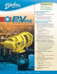
Stationary Sliding Vane Pumps: 5 to 2200 GPM<br />
Refined Fuels, Liquefied Gases, Solvents,Process<br />
ProVane® Motor Speed Sliding Vane Pumps<br />
1 to 100 GPM: Stainless and Ductile Iron<br />
For low / medium viscosity process applications<br />
Stainless Steel Sliding Vane Pumps<br />
1 to 265 GPM: Acids, Brines, Sugars, Syrups,<br />
Beer, Beet Juice, Cider, Flavor Extracts, etc.<br />
Hand Operated Pumps<br />
Dispensing, Transfer, In-line<br />
Mobile Sliding Vane Pumps: 10 to 500 GPM<br />
Refined Fuels, Liquefied Gases, Solvents<br />
Magnetic Drive Pumps<br />
Stainless Steel: 14 to 215 GPM<br />
Reciprocating Gas Compressors<br />
Liquefied Gas Transfer, Boosting, Vapor Recovery<br />
Accessories<br />
Gear Reducers, Bypass Valves, Strainers<br />
Visit www.blackmer.com for complete information on all Blackmer products<br />
1809 Century Avenue, Grand Rapids, Michigan 49503-1530 U.S.A.<br />
Telephone: (616) 241-1611 • Fax: (616) 241-3752<br />
E-mail: blackmer@blackmer.com • Internet Address: www .blackmer.com