INLET BARRIER FILTER SYSTEM - Donaldson Company, Inc.
INLET BARRIER FILTER SYSTEM - Donaldson Company, Inc.
INLET BARRIER FILTER SYSTEM - Donaldson Company, Inc.

You also want an ePaper? Increase the reach of your titles
YUMPU automatically turns print PDFs into web optimized ePapers that Google loves.
Document Number: AFS-EC130-IBF-ICA<br />
Revision: D<br />
Date: 4 November 2011<br />
INSTRUCTIONS FOR CONTINUED AIRWORTHINESS<br />
<strong>INLET</strong> <strong>BARRIER</strong> <strong>FILTER</strong> <strong>SYSTEM</strong><br />
for the<br />
Eurocopter France<br />
Models EC130B4 and AS350B3 w/Dual Hydraulics<br />
FAA STC No. SR02560CH<br />
17891 Chesterfield Airport Road<br />
Chesterfield, MO 63005<br />
COPYRIGHT© 2008<br />
Aerospace Filtration Systems, <strong>Inc</strong>.<br />
UNPUBLISHED — ALL RIGHTS RESERVED<br />
LIMITED and/or RESTRICTED RIGHTS NOTICE<br />
This document, along with its drawings and photographs, contains Trade Secrets and/or Commercial or<br />
Financial Information that is proprietary to Aerospace Filtration Systems, <strong>Inc</strong>. (AFS) under 5 USC 552 as<br />
amended, and is Prohibited from Public Disclosure by 18 USC 1905. Do not duplicate or disclose outside<br />
the U.S. Government without the express written permission of Aerospace Filtration Systems, <strong>Inc</strong>.<br />
The Government's rights to use, modify, reproduce, release, perform, display, or disclose these technical<br />
data are restricted to the purpose of evaluating AFS’s design for FAA commercial certification and<br />
airworthiness consideration only. Any reproduction of technical data or portions thereof marked with this<br />
legend, or referring to this legend, must also reproduce the markings and legend. Any person, other than the<br />
Government, who has been provided access to such data must promptly notify: Aerospace Filtration<br />
Systems, <strong>Inc</strong>., Attn: Business Manager, 17891 Chesterfield Airport Road, Chesterfield, MO 63005<br />
The data subject to this limited/restricted rights notice is contained on all pages.
AFS-EC130-IBF-ICA Aerospace Filtration Systems, <strong>Inc</strong>.<br />
Revision: D Proprietary Information<br />
PROPRIETARY DATA STATEMENT<br />
This data, excluding Chapter 4, Airworthiness Limitations, are proprietary to<br />
Aerospace Filtration Systems, <strong>Inc</strong>. Disclosure, reproduction, or use of<br />
these data for any purpose other than helicopter operation and/or<br />
maintenance is forbidden without prior written authorization from<br />
Aerospace Filtration Systems, <strong>Inc</strong>.<br />
EFFECTIVITY<br />
Effectivity for this ICA is for all Eurocopter model EC130B4 and<br />
AS350B3 w/dual hydraulics helicopters with the Aerospace Filtration<br />
Systems, <strong>Inc</strong>. (AFS) Inlet Barrier Filter (IBF) System installed.<br />
Use or disclosure of this material is subject AFS Eurocopter EC130 IBF<br />
i<br />
to the restrictions on the title page Instructions for Continued Airworthiness
AFS-EC130-IBF-ICA Aerospace Filtration Systems, <strong>Inc</strong>.<br />
Revision: D Proprietary Information<br />
LOG OF REVISIONS<br />
Revision No. Revision Description Release Date<br />
IR Initial Release 10-25-07<br />
A Revised Appendix A 04-04-08<br />
B Added AS350B3 w/dual hydraulics to the aircraft eligibility 6-23-08<br />
C Added Optional Filter 121300-103 to Appendix 4-27-10<br />
D Revised Appendix A 11-4-11<br />
Use or disclosure of this material is subject AFS Eurocopter EC130 IBF<br />
iii<br />
to the restrictions on the title page Instructions for Continued Airworthiness
AFS-EC130-IBF-ICA Aerospace Filtration Systems, <strong>Inc</strong>.<br />
Revision: D Proprietary Information<br />
INSTRUCTIONS FOR CONTINUED AIRWORTHINESS<br />
For the Aerospace Filtration Systems Engine Inlet Barrier Filter System<br />
Installed on the Eurocopter France Models EC130B4 and AS350B3 w/Dual Hydraulics<br />
Table of Contents<br />
1 INTRODUCTION ............................................................................................................................................... 1<br />
1.1 SCOPE OF THIS MANUAL ............................................................................................................................ 1<br />
1.2 USE OF THIS MANUAL ................................................................................................................................ 1<br />
1.3 DEFINITIONS / TERMINOLOGY ................................................................................................................. 1<br />
1.4 ACRONYMS ................................................................................................................................................... 3<br />
1.5 WARNINGS, CAUTIONS, AND NOTES ...................................................................................................... 4<br />
1.6 UNITS OF MEASURE .................................................................................................................................... 4<br />
1.7 REFERENCE PUBLICATIONS ..................................................................................................................... 4<br />
1.8 LIST OF APPLICABLE PUBLICATIONS ..................................................................................................... 4<br />
1.9 DISTRIBUTION OF CHANGES .................................................................................................................... 5<br />
1.10 INDICATION OF CHANGES .................................................................................................................... 5<br />
1.11 <strong>SYSTEM</strong> DESCRIPTION AND OVERVIEW ........................................................................................... 5<br />
2 AIRWORTHINESS LIMITATIONS ................................................................................................................ 8<br />
2.1 FAA APPROVAL BLOCK .............................................................................................................................. 8<br />
2.2 GENERAL ....................................................................................................................................................... 9<br />
2.3 <strong>FILTER</strong> RETIREMENT LIFE ......................................................................................................................... 9<br />
2.4 LIFE LIMITED COMPONENTS .................................................................................................................... 9<br />
3 INSPECTION REQUIREMENTS AND OVERHAUL ................................................................................. 10<br />
3.1 INSPECTION REQUIREMENTS ................................................................................................................. 10<br />
3.2 GENERAL REQUIREMENTS ...................................................................................................................... 10<br />
3.2.1 <strong>FILTER</strong> ASSEMBLY INSPECTION ...................................................................................................... 10<br />
3.2.2 STRUCTURAL COMPONENT INSPECTIONS .................................................................................... 11<br />
3.2.3 <strong>SYSTEM</strong>S AND ELECTRICAL COMPONENT INSPECTIONS ........................................................... 11<br />
3.2.4 IBF BYPASS COCKPIT SWITCH FUNCTION CHECK ...................................................................... 12<br />
3.3 OVERHAUL REQUIREMENTS .................................................................................................................. 12<br />
4 ACCESS PANELS ............................................................................................................................................ 15<br />
4.1 GENERAL DESCRIPTION ........................................................................................................................... 15<br />
4.2 ACCESS FOR <strong>FILTER</strong> SERVICING ............................................................................................................ 15<br />
4.3 ACCESS FOR MAINTENANCE .................................................................................................................. 15<br />
5 STORAGE ......................................................................................................................................................... 16<br />
5.1 STORAGE ..................................................................................................................................................... 16<br />
6 PLACARDS, DATA PLATES, AND MARKINGS ....................................................................................... 17<br />
6.1 MARKING – PART NUMBER / PMA / SERIALIZATION ................................................................................... 17<br />
6.2 DATA PLATE – <strong>FILTER</strong> ASSEMBLY ........................................................................................................ 17<br />
6.3 PLACARDS / MARKINGS - COCKPIT ....................................................................................................... 17<br />
7 SERVICING ...................................................................................................................................................... 18<br />
7.1 AUTHORIZED MATERIALS ....................................................................................................................... 18<br />
7.2 <strong>FILTER</strong> SERVICE INTERVALS .................................................................................................................. 18<br />
7.2.1 GENERAL REQUIREMENTS ............................................................................................................... 18<br />
7.2.2 PREPARED FIELD OPERATIONS ...................................................................................................... 19<br />
7.2.3 SEVERE ENVIRONMENT OPERATIONS ............................................................................................ 19<br />
7.3 <strong>FILTER</strong> ASSEMBLY SERVICING .............................................................................................................. 20<br />
Use or disclosure of this material is subject AFS Eurocopter EC130 IBF<br />
iv<br />
to the restrictions on the title page Instructions for Continued Airworthiness
AFS-EC130-IBF-ICA Aerospace Filtration Systems, <strong>Inc</strong>.<br />
Revision: D Proprietary Information<br />
7.3.1 <strong>FILTER</strong> PRE-CLEANING ..................................................................................................................... 20<br />
7.3.2 <strong>FILTER</strong> CLEANING .............................................................................................................................. 20<br />
7.3.3 <strong>FILTER</strong> DRYING .................................................................................................................................. 21<br />
7.3.4 <strong>FILTER</strong> OILING.................................................................................................................................... 21<br />
7.4 STRUCTURAL COMPONENT SERVICING .............................................................................................. 22<br />
7.5 <strong>SYSTEM</strong>S AND ELECTRICAL SERVICING ............................................................................................. 23<br />
7.6 ENGINE WATER WASH.............................................................................................................................. 23<br />
7.7 AIRCRAFT WASHING ................................................................................................................................ 23<br />
8 TROUBLESHOOTING AND MAINTENANCE .......................................................................................... 24<br />
8.1 MAINTENANCE GENERAL ....................................................................................................................... 24<br />
8.2 COMPONENTS - GENERAL DESCRIPTION ............................................................................................. 25<br />
8.2.1 <strong>FILTER</strong> ASSY / <strong>FILTER</strong> SEAL .............................................................................................................. 25<br />
8.2.2 STRUCTURAL COMPONENTS ........................................................................................................... 25<br />
8.2.3 <strong>SYSTEM</strong>S AND ELECTRICAL COMPONENTS ................................................................................... 25<br />
8.3 <strong>FILTER</strong> ASSY / <strong>FILTER</strong> SEAL .................................................................................................................... 26<br />
8.3.1 <strong>FILTER</strong> ASSY ........................................................................................................................................ 26<br />
8.3.2 <strong>FILTER</strong> SEAL ........................................................................................................................................ 30<br />
8.4 STRUCTURAL COMPONENTS .................................................................................................................. 31<br />
8.4.1 EUROCOPTER EC130B4/AS350B3 AIR INDUCTION COWLING .................................................... 31<br />
8.4.2 BYPASS DOOR ..................................................................................................................................... 32<br />
8.4.3 BYPASS DOOR SEAL ........................................................................................................................... 33<br />
8.4.4 STRUCTURAL ASSEMBLY................................................................................................................... 34<br />
8.5 <strong>SYSTEM</strong>S AND ELECTRICAL COMPONENTS ........................................................................................ 36<br />
8.5.1 COCKPIT SWITCH/INDICATOR ......................................................................................................... 36<br />
8.5.2 DIFFERENTIAL PRESSURE SWITCH ................................................................................................ 37<br />
8.5.3 <strong>FILTER</strong> MAINTENANCE AID .............................................................................................................. 40<br />
8.5.4 ACTUATOR ........................................................................................................................................... 42<br />
8.5.5 WIRING, WIRING HARNESS, CONNECTORS, BACKSHELLS, CIRCUIT BREAKER, RELAY ......... 46<br />
8.6 FASTENER LISTING ................................................................................................................................... 47<br />
8.7 PROTECTIVE TREATMENT ....................................................................................................................... 47<br />
8.8 TROUBLESHOOTING GUIDE .................................................................................................................... 49<br />
8.9 SPECIAL TOOLS / SPECIAL EQUIPMENT ............................................................................................... 50<br />
8.9.1 CONSUMABLE MATERIALS, SUPPLIES, AND PROTECTIVE TREATMENT SPECIFICATIONS .. 50<br />
9 ICA APPENDIX A – ILLUSTRATED PARTS BREAKDOWN ............................................................... A-1<br />
Use or disclosure of this material is subject AFS Eurocopter EC130 IBF<br />
v<br />
to the restrictions on the title page Instructions for Continued Airworthiness
AFS-EC130-IBF-ICA Aerospace Filtration Systems, <strong>Inc</strong>.<br />
Revision: D Proprietary Information<br />
Table of Pictures<br />
Picture 1: FMA Operation .............................................................................................................. 13<br />
Picture 2: Cockpit Switch/Indicator ................................................................................................ 17<br />
Picture 3: Circuit Breaker ............................................................................................................... 17<br />
Picture 4: Oiling Filter Media ......................................................................................................... 22<br />
Picture 5: Hand Seamer Used to Straighten or Crimp Pleats .......................................................... 28<br />
Picture 6: Test Setup with Manometer ............................................................................................ 40<br />
Table of Tables<br />
Table 1: Inspection Intervals ........................................................................................................... 14<br />
Table 2: Protective Treatment for Components .............................................................................. 47<br />
Table 3: Troubleshooting Guide ..................................................................................................... 49<br />
Table 4: Consumable Materials, Supplies and Protective Treatment Specifications ..................... 50<br />
Table of Figures<br />
Figure 1: IBF System Installation ..................................................................................................... 7<br />
Figure 2: FMA Reset Location ....................................................................................................... 13<br />
Figure 3: Example of Filter Assembly Data Plate .......................................................................... 17<br />
Figure 4: Test Equipment Setup ..................................................................................................... 39<br />
Use or disclosure of this material is subject AFS Eurocopter EC130 IBF<br />
vi<br />
to the restrictions on the title page Instructions for Continued Airworthiness
AFS-EC130-IBF-ICA Aerospace Filtration Systems, <strong>Inc</strong>.<br />
Revision: D Proprietary Information<br />
THIS PAGE INTENTIONALLY LEFT BLANK<br />
Use or disclosure of this material is subject AFS Eurocopter EC130 IBF<br />
vii<br />
to the restrictions on the title page Instructions for Continued Airworthiness
AFS-EC130-IBF-ICA Aerospace Filtration Systems, <strong>Inc</strong>.<br />
Revision: D Proprietary Information<br />
1 INTRODUCTION<br />
1.1 SCOPE OF THIS MANUAL<br />
These Instructions for Continued Airworthiness (ICA) provide the information required to do the<br />
maintenance and repair of the Aerospace Filtration Systems, <strong>Inc</strong>. (AFS) Inlet Barrier Filter (IBF)<br />
system installation on the Eurocopter Models EC130 and AS350B3 w/dual hydraulics helicopters.<br />
The ICA should be used in conjunction with all pertinent Eurocopter Models EC130B4 and<br />
AS350B3 series manuals and all publications listed in the List of Applicable Publications (LOAP).<br />
NOTE<br />
Thoroughly review and become familiar with the Appendix A –<br />
Illustrated Parts Breakdown section of this ICA before performing<br />
maintenance on the IBF system.<br />
1.2 USE OF THIS MANUAL<br />
The instructions that are given in this manual and those that have been changed by revisions,<br />
bulletins and/or alerts issued by AFS, Eurocopter or the Airworthiness Directives issued by the<br />
local Aviation Authority, shall be strictly followed.<br />
1.3 DEFINITIONS / TERMINOLOGY<br />
Actuator An electromechanical actuator used to open / close the bypass door.<br />
Air induction screen Screen installed in the engine inlet on baseline configuration aircraft<br />
in lieu of the Sand Filter or the IBF, to prevent engine foreign object<br />
damage.<br />
Air induction cowling This cowling houses the major kit components including the IBF<br />
filter assembly, adaptor frame, bypass door assembly and associated<br />
wiring.<br />
Brownout A brownout condition is a zero visibility condition usually caused by<br />
hovering in a dusty environment.<br />
Bypass The bypass is an alternate air inlet used only when the main engine<br />
air inlet through the filter becomes clogged or blocked.<br />
Bypass door Door is located just aft of the filter that when opened by the actuator<br />
allows unfiltered air to be drawn into the engine.<br />
Use or disclosure of this material is subject 1 AFS Eurocopter EC130 IBF<br />
to the restrictions on the title page Instructions for Continued Airworthiness
AFS-EC130-IBF-ICA Aerospace Filtration Systems, <strong>Inc</strong>.<br />
Revision: D Proprietary Information<br />
Cockpit switch/indicator A push button switch, labeled “IBF”, is used to OPEN or CLOSE the<br />
bypass door. This switch is normally CLOSED and is depressed to<br />
the OPEN position only when the cockpit indicator, an amber<br />
caution “<strong>FILTER</strong>” light in the switch, illuminates.<br />
The “<strong>FILTER</strong>” portion of the switch illuminates any time the<br />
differential pressure reaches or exceeds a preset value.<br />
The “BYPASS” portion of the switch illuminates when the bypass<br />
door is completely open.<br />
Differential pressure Drop in pressure across the filter assembly, which is measured by the<br />
differential pressure switch and the filter maintenance aid.<br />
Delta P switch Differential pressure switch.<br />
Filter Barrier type filter media made of multi-layers of cotton gauze<br />
saturated with specially formulated oil that forms a tack barrier that<br />
increases the capture efficiency of the filter.<br />
Filter assembly Filter media supported by pleated stainless steel screen on both sides<br />
and the filter assembly frame components around the perimeter of<br />
the filter media.<br />
Filter assembly frame Structure that frames, retains, and seals the outside edges of the filter<br />
media.<br />
Filter downstream side Clean side of the filter media (i.e. the side of the filter facing<br />
downward).<br />
Filter media A wet media consisting of a multi-layered cotton gauze saturated<br />
with specially formulated oil.<br />
Filter pleats Stainless steel screen is used to form the pleats and hold the filter<br />
media in place.<br />
Filter upstream side Dirty side of the filter media (i.e. the side facing upward into the air<br />
stream on which the dirt collects).<br />
<strong>Inc</strong>hes of water Unit of measure used for the differential pressure measured across<br />
the filter, as measured with a water manometer or similar apparatus.<br />
Oiling Process used to apply a uniform amount of oil on filter media.<br />
On-condition Indicates that servicing of the filter is based on a Filter Maintenance<br />
Aid (FMA) indication in the area marked in “RED”, Engine Power<br />
Check (EPC) results (where a failed EPC is the result of a dirty Filter<br />
Assembly), and / or any “IBF <strong>FILTER</strong>” light indication on the<br />
cockpit indicator.<br />
Use or disclosure of this material is subject 2 AFS Eurocopter EC130 IBF<br />
to the restrictions on the title page Instructions for Continued Airworthiness
AFS-EC130-IBF-ICA Aerospace Filtration Systems, <strong>Inc</strong>.<br />
Revision: D Proprietary Information<br />
Plenum chamber Space between the filter assembly and the engine inlet, and the space<br />
between the Bypass Door and engine inlet.<br />
Service cycle Period starting when a filter is cleaned, oiled and placed into service<br />
and ending when the filter is removed for its next cleaning and<br />
oiling.<br />
1.4 ACRONYMS<br />
AFS = Aerospace Filtration Systems, <strong>Inc</strong>.<br />
FAR = Federal Aviation Regulation<br />
FMA = Filter Maintenance Aid<br />
FMS = Flight Manual Supplement<br />
FOD = Foreign Object Damage<br />
IBF = Inlet Barrier Filter<br />
ICA = Instructions for Continued Airworthiness<br />
IP = Installation Procedures<br />
IPB = Illustrated Parts Breakdown<br />
LOAP = List of Applicable Publications<br />
OAT = Outside Air Temperature<br />
EPC = Engine Power Check<br />
RFM = Rotorcraft Flight Manual<br />
SAE = Society of Automotive Engineers<br />
TCDS = Type Certificate Data Sheet<br />
TIS = Time in Service<br />
Use or disclosure of this material is subject 3 AFS Eurocopter EC130 IBF<br />
to the restrictions on the title page Instructions for Continued Airworthiness
AFS-EC130-IBF-ICA Aerospace Filtration Systems, <strong>Inc</strong>.<br />
Revision: D Proprietary Information<br />
1.5 WARNINGS, CAUTIONS, AND NOTES<br />
Warning, cautions and notes are used throughout this manual to emphasize important and critical<br />
instructions.<br />
WARNING<br />
IF YOU DO NOT FOLLOW THE INSTRUCTIONS THAT ARE GIVEN IN<br />
A WARNING, PERSONAL INJURY CAN OCCUR.<br />
CAUTION<br />
IF YOU DO NOT FOLLOW THE INSTRUCTIONS THAT ARE GIVEN IN<br />
A CAUTION, YOU CAN CAUSE DAMAGE TO THE HELICOPTER OR<br />
TO THE COMPONENTS.<br />
NOTE<br />
A note includes supplemental data about the procedure, the practice, the<br />
condition, etc for the maintenance task.<br />
1.6 UNITS OF MEASURE<br />
U.S. Standard units of measure have been used in preparation of this manual. Typical units used in<br />
this manual include: inches of water measuring differential pressure, inch-pounds of torque, etc.<br />
1.7 REFERENCE PUBLICATIONS<br />
Reserved for future use.<br />
1.8 LIST OF APPLICABLE PUBLICATIONS<br />
Eurocopter France<br />
EC130B4 and AS350B3 Technical Publications<br />
FAA<br />
FAA Advisory Circular, AC 43.13-1B, Acceptable Methods, Techniques, and Practices – Aircraft<br />
Inspection and Repair<br />
Use or disclosure of this material is subject 4 AFS Eurocopter EC130 IBF<br />
to the restrictions on the title page Instructions for Continued Airworthiness
AFS-EC130-IBF-ICA Aerospace Filtration Systems, <strong>Inc</strong>.<br />
Revision: D Proprietary Information<br />
1.9 DISTRIBUTION OF CHANGES<br />
Changes shall be distributed by posting them on the AFS webpage www.afsfilters.com. Each<br />
customer must register to receive access to the webpage via a personalized log-in/password.<br />
NOTE<br />
This webpage should be checked prior to the performance of any<br />
maintenance actions on the IBF system to confirm possession of the latest<br />
FAA approved revision. If access to the internet is not possible, contact AFS<br />
at (636) 300-5200 for assistance.<br />
1.10 INDICATION OF CHANGES<br />
All changes will be complete revisions with all pages marked with the latest revision letter. All<br />
changes since the last revision shall be marked with a black vertical bar in the left side of the page.<br />
1.11 <strong>SYSTEM</strong> DESCRIPTION AND OVERVIEW<br />
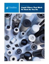
a. The Eurocopter EC130B4/AS350B3 IBF provides a barrier type filter assembly that mounts to<br />
the top of the Engine Air Induction Cowling in the same location and in lieu of the Air<br />
Induction Screen. The IBF installation requires only minor modifications to the existing Air<br />
Induction Cowling. The IBF provides aircraft owner/operators a high performance engine air<br />
filtration option that provide excellent filtration efficiency. The IBF will increase the life of the<br />
engine through a dramatic reduction in erosion resulting from the substantial increase in<br />
filtration efficiency without degrading engine performance. The AFS IBF system provides dust<br />
separation efficiencies exceeding 99% for Society of Automotive Engineers (SAE) AC Coarse<br />
and AC Fine dust as defined in specification SAE J726, Air Cleaner Test Code.<br />
b. The IBF system does not interfere with any of the commercial items installed in the Eurocopter<br />
EC130B4 and AS350B3 production aircraft. The IBF is a complete system in which safety,<br />
functionality and serviceability were major considerations in the design process. The major kit<br />
components include the filter assembly, cockpit switch/indicator, structural assembly (which<br />
includes the bypass door assembly, actuator, differential pressure switch, filter maintenance aid<br />
and wiring harness). Figure 1, located at the end of this chapter, provides an exploded view of<br />
the major kit components with the exception of the cockpit switch, indicator light and wiring<br />
harness. For a detailed illustration of all kit components, see the Appendix A – Illustrated Parts<br />
Breakdown.<br />
c. The major components making up the bypass system include the bypass door, actuator, wiring<br />
harness, cockpit switch, indicator light, and differential pressure switch.<br />
d. The IBF system provides a means of monitoring the condition of the filter both in-flight and on<br />
the ground, and a bypass capability should flow through the filter become restricted. In-flight,<br />
when the differential pressure reaches the pre-set value the cockpit indicator light illuminates<br />
alerting the pilot that the filter is becoming restricted causing the engine to operate less<br />
Use or disclosure of this material is subject 5 AFS Eurocopter EC130 IBF<br />
to the restrictions on the title page Instructions for Continued Airworthiness
AFS-EC130-IBF-ICA Aerospace Filtration Systems, <strong>Inc</strong>.<br />
Revision: D Proprietary Information<br />
efficiently. At this point, the IBF is operating at approximately the same inlet differential<br />
pressure normally experienced with the Sand Filter installed. Upon illumination of the IBF<br />
“<strong>FILTER</strong>” caution light, the pilot must closely monitor the engine instruments and if engine<br />
performance degradation is evident the pilot should push the cockpit switch, labeled IBF, to<br />
activate the actuator and open the bypass door. This will cause the top light, labeled “<strong>FILTER</strong>”,<br />
to extinguish and the bottom light, labeled “BYPASS”, to illuminate. The electromechanically<br />
actuated bypass door permits unfiltered air to enter the engine inlet plenum chamber should the<br />
filter media become obstructed, and can be opened or closed as required. On the ground, a Filter<br />
Maintenance Aid, mounted to the forward L/H side of the firewall, which can be viewed by<br />
opening the MGB Cowling, displays the maximum differential pressure across the filter reached<br />
during the last flight. It is accessible only on the ground, providing the pilot or mechanic the<br />
ability to visually gauge the current condition of the filter. This gives the mechanic the ability to<br />
forecast the timing of the next service cycle. The Filter Maintenance Aid can be reset by<br />
depressing the yellow button marked “PUSH TO RESET” located on the end of the Filter<br />
Maintenance Aid (See Pictures 1 & 2).<br />
e. The design of the bypass system allows the ground crew to cycle the bypass door with power on<br />
the aircraft. The switch can be pushed to actuate the bypass door open, and then pushed again to<br />
actuate it closed. Full functional verification of the bypass system including all<br />
electromechanical components and the filter maintenance aid is possible during routine<br />
maintenance (see Chapter 8).<br />
f. Removal of the filter assembly for servicing is easily achieved by removal of thirteen captive<br />
fasteners. The filter assembly can then be lifted out of the engine cowling.<br />
g. The engine wash can be accomplished in the same manner prior to installing the IBF system.<br />
Use or disclosure of this material is subject 6 AFS Eurocopter EC130 IBF<br />
to the restrictions on the title page Instructions for Continued Airworthiness
AFS-EC130-IBF-ICA Aerospace Filtration Systems, <strong>Inc</strong>.<br />
Revision: D Proprietary Information<br />
Figure 1: IBF System Installation<br />
Use or disclosure of this material is subject 7 AFS Eurocopter EC130 IBF<br />
to the restrictions on the title page Instructions for Continued Airworthiness
AFS-EC130-IBF-ICA Aerospace Filtration Systems, <strong>Inc</strong>.<br />
Revision: D Proprietary Information<br />
2 AIRWORTHINESS LIMITATIONS<br />
2.1 FAA APPROVAL BLOCK<br />
The Airworthiness Limitations Section is FAA approved and specifies maintenance required under<br />
Secs. 43.16 and 91.403 of the Federal Aviation Regulations unless an alternative program has been<br />
FAA approved.<br />
Revision Date of FAA Signature FAA Signature<br />
Initial Release Superseded<br />
A Superseded<br />
B Superseded<br />
C Aug 17, 2011 Timothy Smyth<br />
D Limitations not affected<br />
Use or disclosure of this material is subject 8 AFS Eurocopter EC130 IBF<br />
to the restrictions on the title page Instructions for Continued Airworthiness
AFS-EC130-IBF-ICA Aerospace Filtration Systems, <strong>Inc</strong>.<br />
Revision: D Proprietary Information<br />
2.2 GENERAL<br />
The Airworthiness Limitations for the AFS Inlet Barrier Filtration system (IBF) as installed on<br />
Eurocopter France model EC130B4 and AS350B3 w/dual hydraulics helicopters are FAA<br />
approved.<br />
NOTE<br />
The retirement life given or the failure to give a retirement life to a<br />
component does not constitute a warranty of any kind. The only warranty<br />
applicable to any component is the warranty included in the Purchase<br />
Agreement for the helicopter or the component.<br />
2.3 <strong>FILTER</strong> RETIREMENT LIFE<br />
After fifteen (15) cleaning and oiling cycles, the filter must be removed from service at the next<br />
servicing interval. The filter data tag is scribed after each cleaning and oiling cycle (see Section 6-<br />
2). When all numerals (1-15) on the data tag have been scribed out, the filter shall be removed<br />
from service at the next service interval. No further cleaning cycles are authorized.<br />
2.4 LIFE LIMITED COMPONENTS<br />
The only life limited component features are the number of cleanings of the filter assembly. See<br />
Section 2.3.<br />
Use or disclosure of this material is subject 9 AFS Eurocopter EC130 IBF<br />
to the restrictions on the title page Instructions for Continued Airworthiness
AFS-EC130-IBF-ICA Aerospace Filtration Systems, <strong>Inc</strong>.<br />
Revision: D Proprietary Information<br />
3 INSPECTION REQUIREMENTS AND OVERHAUL<br />
3.1 INSPECTION REQUIREMENTS<br />
3.2 GENERAL REQUIREMENTS<br />
a. Inspection of the IBF system consists of, in general terms, inspection of the filter assembly,<br />
inspection of the structural components, inspection of electrical and system components, and a<br />
special inspection at three specified points based on hours after initial installation. The<br />
components of the system are divided, generally as a scope of work, into Filter Assembly, Seal,<br />
Structural Components, and Systems and Electrical components as is done throughout the<br />
manual.<br />
b. Refer to the Appendix A - Illustrated Parts Breakdown for component illustrations that provide<br />
supplemental information relative to proper assembly configuration, orientation, and locations<br />
for all components to be inspected per Chapter 3 and Table 1. Refer to Appendix A, Figure A-1<br />
for the primary kit components. Refer to Figures A-2 through A-10 for structural details. Refer<br />
to Figure A-11 for electrical components.<br />
c. Table 1 gives a recommended inspection schedule for the components of the system. The<br />
Trouble-Shooting Guide, Table 3 found near the end of Chapter 8, also gives additional<br />
guidance when performing inspections and encountering trouble with the system. Chapter 8 also<br />
provides specific inspection guidance and removal/installation procedures for each component<br />
and is structured in the same three major groups as discussed above.<br />
3.2.1 <strong>FILTER</strong> ASSEMBLY INSPECTION<br />
a. The following inspections pertain to the barrier filter assembly and associated components,<br />
which include the filter assembly (i.e. filter frame and filter media) and all associated<br />
seals/fasteners.<br />
b. ON-CONDITION: Any FMA indication in the “RED”, “<strong>FILTER</strong>” light indication of the IBF<br />
cockpit indicator or failed EPC requires a visual inspection in accordance with Chapter 8.<br />
c. VISUAL: All filter assembly components are to be visually inspected at every annual<br />
inspection in accordance with Table 1 checking for the following: filter media for tears,<br />
punctures, uneven or damaged pleats; seals for tears/damage; frame components for corrosion,<br />
cracks, distortions near holes, and check for missing or damaged fasteners.<br />
Use or disclosure of this material is subject 10 AFS Eurocopter EC130 IBF<br />
to the restrictions on the title page Instructions for Continued Airworthiness
AFS-EC130-IBF-ICA Aerospace Filtration Systems, <strong>Inc</strong>.<br />
Revision: D Proprietary Information<br />
3.2.2 STRUCTURAL COMPONENT INSPECTIONS<br />
VISUAL: All structural IBF components are to be inspected in accordance with Table 1<br />
every 100 hours and annual inspection. These components include the following: Eurocopter<br />
Air Induction Cowling (OEM equipment), Filter Assembly, Bypass Door Assembly, Upper<br />
Fairing Assembly, Engine Interface Assembly, and the Engine Plenum Extension.<br />
3.2.3 <strong>SYSTEM</strong>S AND ELECTRICAL COMPONENT INSPECTIONS<br />
a. VISUAL: The systems and electrical components are to be visually inspected in accordance<br />
with Table 1 every 100 hours and annual inspection. These components include the following:<br />
Wiring, Wiring Harness, Connectors, Backshells, Circuit Breaker, Cockpit Switch/ Indicator,<br />
Differential Pressure Switch, Filter Maintenance Aid, and Actuator.<br />
b. FUNCTION CHECK: Certain systems and electrical components are also to be function<br />
checked in accordance with Table 1 every annual inspection. These components include the<br />
following: Circuit Breaker, Cockpit Switch/Indicator, Differential Pressure Switch, Filter<br />
Maintenance Aid, and Actuator.<br />
c. FMA CHECK: The FMA check is performed to ascertain the current condition of the filter or to<br />
gage the trend in accumulation of dirt. The FMA check is only a check of the indicator reading<br />
(See Picture 1). As such it is not considered an inspection of the FMA. The inspection Table 1<br />
does not require a specific “inspection” interval of the FMA. The condition of the Filter<br />
Assembly and its accumulation of dirt will show up as an indication on the FMA. Thus<br />
operational environment, more so than time in service, dictate how often the FMA should be<br />
checked in order to help determine the next Filter Assembly service requirement. It is an aid in<br />
scheduling the Filter Assembly servicing. At any time prior to an FMA indication in the “RED”<br />
(See Picture 1), a failed EPC, or a IBF “<strong>FILTER</strong>” indication on the cockpit indicator, when<br />
maintenance or flight personnel see a trend based on the FMA readings over time that would<br />
warrant servicing of the filter due to operational considerations, such as when the aircraft will<br />
be operated in a remote or off-site location without the ability to readily service the filter, the<br />
filter may be serviced, or replaced. See Section 7.2 for a further description of the use of the<br />
FMA as it relates to the Filter Assembly service interval. See filter servicing Section 7.3.<br />
NOTE<br />
The Filter Maintenance Aid is designed to hold the highest differential<br />
pressure across the filter assembly reached during the last flight, and should<br />
be reset after servicing of the filter assembly by depressing the yellow button<br />
marked “PUSH TO RESET” located on the end of the filter maintenance aid<br />
(See Picture 1).<br />
Use or disclosure of this material is subject 11 AFS Eurocopter EC130 IBF<br />
to the restrictions on the title page Instructions for Continued Airworthiness
AFS-EC130-IBF-ICA Aerospace Filtration Systems, <strong>Inc</strong>.<br />
Revision: D Proprietary Information<br />
3.2.4 IBF BYPASS COCKPIT SWITCH FUNCTION CHECK<br />
FUNCTION CHECK: A function check of the IBF BYPASS Cockpit Switch is to be<br />
performed every 100 hours (See Table 1). Perform the function check as follows: (1) With<br />
aircraft power ON, push the IBF BYPASS switch in, the BYPASS light should illuminate<br />
and the bypass door should open, visually verify this has happened. (2) Push the IBF<br />
BYPASS switch in, and the BYPASS light should go out and the bypass door should close,<br />
visually verify this has happened. Turn aircraft power OFF. If conditions are not met refer to<br />
Table 3 Troubleshooting Guide.<br />
3.3 OVERHAUL REQUIREMENTS<br />
There are no overhaul intervals or requirements applicable to this product at this time.<br />
Use or disclosure of this material is subject 12 AFS Eurocopter EC130 IBF<br />
to the restrictions on the title page Instructions for Continued Airworthiness
AFS-EC130-IBF-ICA Aerospace Filtration Systems, <strong>Inc</strong>.<br />
Revision: D Proprietary Information<br />
YELLOW<br />
Indicator<br />
Picture 1: FMA Operation<br />
Figure 2: FMA Reset Location<br />
RED Zone<br />
GREEN Zone<br />
YELLOW<br />
RESET Button<br />
“YELLOW Indicator” position relative to SAFE OPERATING ZONE (“GREEN<br />
Zone”) or SERVICE <strong>FILTER</strong> (“RED Zone”) markings defines current filter condition,<br />
and pushing “YELLOW RESET Button” resets indicator.<br />
Open the MGB<br />
Cowling to Locate<br />
the FMA mounted to<br />
the forward side of<br />
the firewall.<br />
Use or disclosure of this material is subject 13 AFS Eurocopter EC130 IBF<br />
to the restrictions on the title page Instructions for Continued Airworthiness
AFS-EC130-IBF-ICA Aerospace Filtration Systems, <strong>Inc</strong>.<br />
Revision: D Proprietary Information<br />
Components<br />
Filter Assembly as<br />
defined in para. 3.2.1.<br />
Structural Components<br />
as defined in para. 3.2.2.<br />
Systems and Electrical<br />
Components as defined<br />
in para. 3.2.3.<br />
IBF Bypass Cockpit<br />
Switch as defined in<br />
para. 3.2.4.<br />
Inspection<br />
Type<br />
Table 1: Inspection Intervals<br />
Inspection<br />
Inspection Intervals<br />
Scheduled<br />
Time In Service Notes<br />
100 Hrs. Annual<br />
Conditional 1. Visual 300 hrs / 1 yr 2, 3, 4, 5, 7<br />
Scheduled 2. Visual X 1, 2, 4, 6, 7<br />
Scheduled 1. Visual X X 1, 2, 4, 6<br />
Scheduled 1. Visual X X 1, 2, 4, 6<br />
Scheduled 2. Function Check X 1, 2, 4, 5<br />
Scheduled 1. Function Check X 8<br />
NOTES:<br />
1. Refer to Chapter 8 for specific inspection requirements and functional check procedures.<br />
2. Refer to Chapter 4 for access information.<br />
3. IBF <strong>FILTER</strong> light or failed EPC. This inspection is required any time an IBF <strong>FILTER</strong> light indication or<br />
failed EPC is reported by the pilot.<br />
4. Reference Appendix A – Illustrated Parts Breakdown.<br />
5. Reference Trouble-Shooting Guide, Table 3 of this manual.<br />
6. Perform a visual inspection checking for deformation, buckling, corrosion, cracks, dents, tears, or other signs<br />
of damage and repair in accordance with the procedures in Chapter 8.<br />
7. The maximum filter service interval between cleanings under any conditions is 300 flight hours or 1 year<br />
TIS, whichever comes first. Up to the TIS limit, the inspection of the Filter Assembly is “On-Condition” based<br />
on an FMA indication in the “RED”, any “IBF <strong>FILTER</strong>” light indication on the Cockpit Indicator, and / or upon<br />
a failed EPC (where the failed EPC is the result of a dirty Filter Assembly).<br />
8. If conditions are not met refer to the Table 3 Troubleshooting Guide in this manual.<br />
Use or disclosure of this material is subject 14 AFS Eurocopter EC130 IBF<br />
to the restrictions on the title page Instructions for Continued Airworthiness
AFS-EC130-IBF-ICA Aerospace Filtration Systems, <strong>Inc</strong>.<br />
Revision: D Proprietary Information<br />
4 ACCESS PANELS<br />
4.1 GENERAL DESCRIPTION<br />
This chapter addresses how to access the IBF system installation for servicing or maintenance.<br />
4.2 ACCESS FOR <strong>FILTER</strong> SERVICING<br />
Filter servicing requires removal of the filter assembly. See Chapter 8 for filter assembly<br />
removal/installation procedures and Chapter 7 for filter servicing procedures.<br />
4.3 ACCESS FOR MAINTENANCE<br />
Access for maintenance of the system components located below the bypass door assembly (i.e.<br />
actuator, delta p switch, etc.) requires removal of the floor closeout on the bottom of the structural<br />
assembly. See Chapter 8 for component removal/installation procedures, inspection,<br />
troubleshooting guide, adjustment/calibration/repair procedures.<br />
Use or disclosure of this material is subject 15 AFS Eurocopter EC130 IBF<br />
to the restrictions on the title page Instructions for Continued Airworthiness
AFS-EC130-IBF-ICA Aerospace Filtration Systems, <strong>Inc</strong>.<br />
Revision: D Proprietary Information<br />
5 STORAGE<br />
5.1 STORAGE<br />
CAUTION<br />
NEVER INSTALL A <strong>FILTER</strong> ASSEMBLY AND/OR OPERATE AN<br />
AIRCRAFT WITH A <strong>FILTER</strong> INSTALLED WHERE THE <strong>FILTER</strong><br />
MEDIA HAS NOT BEEN PROPERLY OILED.<br />
Long-term storage has no effect on filter assembly reliability if stored unoiled (dry) in a cool, dry<br />
location to discourage possible fungus growth. After storage, the only maintenance to be<br />
performed on the filter before installation on the aircraft is oiling of the filter media. Refer to filter<br />
servicing Section 7.3.<br />
Use or disclosure of this material is subject 16 AFS Eurocopter EC130 IBF<br />
to the restrictions on the title page Instructions for Continued Airworthiness
AFS-EC130-IBF-ICA Aerospace Filtration Systems, <strong>Inc</strong>.<br />
Revision: D Proprietary Information<br />
6 PLACARDS, DATA PLATES, AND MARKINGS<br />
6.1 MARKING – Part Number / PMA / Serialization<br />
The IBF system is marked on the RH structural assembly to contain the top level part number, the<br />
serial number of the system, and the FAA PMA markings, if applicable.<br />
6.2 DATA PLATE – <strong>FILTER</strong> ASSEMBLY<br />
After the filter assembly has been serviced an “X” is marked through one of the unmarked boxes<br />
on the serviceability tag (see Figure 3). When the last unmarked box is crossed through, the filter<br />
assembly will have to be replaced at the next servicing. See Chapter 7 for servicing procedures.<br />
Figure 3: Example of Filter Assembly Data Plate<br />
6.3 PLACARDS / MARKINGS - COCKPIT<br />
a. The IBF utilizes a cockpit switch/indicator labeled “IBF” on the aircraft instrument panel. The<br />
top half illuminates an amber “<strong>FILTER</strong>” message when the IBF differential pressure has<br />
reached a preset value. The bottom half illuminates an amber “BYPASS” message when the<br />
actuator has been energized and the bypass door is open. See Picture 2 for markings.<br />
b. The IBF circuit breaker in the lower center console is marked “IBF”. See Picture 3 for<br />
markings.<br />
Picture 2: Cockpit Switch/Indicator<br />
Picture 3: Circuit Breaker<br />
Use or disclosure of this material is subject 17 AFS Eurocopter EC130 IBF<br />
to the restrictions on the title page Instructions for Continued Airworthiness
AFS-EC130-IBF-ICA Aerospace Filtration Systems, <strong>Inc</strong>.<br />
Revision: D Proprietary Information<br />
7 SERVICING<br />
7.1 AUTHORIZED MATERIALS<br />
Service AFS Filter Assembly with only AFS approved filter oil or AFS authorized substitutes.<br />
NOTE<br />
Refer to Chapter 8 for removal, inspection, repair and installation of filter<br />
assembly. Upon satisfactory inspection and any required maintenance of the<br />
filter assembly proceed with the rest of the servicing instructions for the filter<br />
assembly.<br />
7.2 <strong>FILTER</strong> SERVICE INTERVALS<br />
The filter service interval is based on the specific aircraft operating environment. The filter service<br />
intervals section is broken up in three parts: general requirements pertaining to all operations,<br />
specific recommendations for operations on prepared fields, and for operations in severe<br />
environments.<br />
7.2.1 GENERAL REQUIREMENTS<br />
NOTE<br />
The maximum filter service interval between cleanings under any conditions<br />
is 300 flight hours or 1 year TIS, whichever comes first. Up to the TIS limit,<br />
the filter is considered an “on-condition” item.<br />
NOTE<br />
The FMA is an aid to help maintenance personnel and pilots to ascertain the<br />
condition of the filter at any point in time or to trend the accumulation of<br />
dirt on the Filter Assembly over a period of time.<br />
a. Up to the 300 hour / 1 year TIS limit, the “on condition” requirement for servicing the Filter<br />
Assembly is based on a FMA indication, an IBF “<strong>FILTER</strong>” light indication on the cockpit<br />
indicator or upon a failed EPC (where the failed EPC is the result of a dirty Filter Assembly).<br />
b. Any IBF “<strong>FILTER</strong>” indication, where the pressure sensor and indicating system are working<br />
properly, requires servicing of the filter assembly. See filter servicing Section 7.3.<br />
c. The gradual increase in differential pressure across the IBF filter assembly causes an increase in<br />
T4 required to produce a specified torque as measured during the EPC. A failed EPC due to an<br />
increase in differential pressure across the filter is cause for servicing of the filter assembly. See<br />
filter servicing Section 7.3.<br />
Use or disclosure of this material is subject 18 AFS Eurocopter EC130 IBF<br />
to the restrictions on the title page Instructions for Continued Airworthiness
AFS-EC130-IBF-ICA Aerospace Filtration Systems, <strong>Inc</strong>.<br />
Revision: D Proprietary Information<br />
d. Any FMA indication in the area marked in “RED” requires servicing of the filter assembly. See<br />
filter servicing Section 7.3.<br />
e. At any time prior to an IBF “<strong>FILTER</strong>” indication on the cockpit indicator, an FMA indication in<br />
the “RED”, or a failed EPC, when maintenance or flight personnel see a trend on the FMA that<br />
would warrant servicing of the filter due to operational considerations, such as when the aircraft<br />
will be operating in a remote or off-site location without the ability to readily service the filter,<br />
the filter may be serviced, or replaced. See filter servicing Section 7.3.<br />
f. The maximum number of service cycles for the filter assembly (i.e., cleaning / oiling) is limited<br />
to 15 for each filter assembly. The filter assembly includes a data plate that must be scribed to<br />
track filter service cycles in accordance with Section 6.2.<br />
7.2.2 PREPARED FIELD OPERATIONS<br />
a. During typical operations in and out of prepared airfields and landing sites, the IBF filter<br />
assembly will not require frequent servicing. AFS recommends that the filter maintenance aid<br />
(FMA) be checked about every 25 aircraft operating hours following the first installation and<br />
operation of an IBF system on an aircraft. This should be done to gauge the rate of engine<br />
performance degradation due to changes in engine inlet differential pressure as the filters<br />
accumulate dirt in operations considered “prepared fields” operations. Once an interval of time<br />
in flight hours is determined that provide discrete changes in the FMA, this interval can be<br />
repeated as long as there is no change in the environmental operating conditions.<br />
b. This interval can be extended after sufficient flight data has been accumulated to establish a<br />
greater interval. Upon seeing increases in T4 and associated decreases in temperature margin /<br />
available power, the inspection interval should again be shortened to about every 25 hours or<br />
less to enable scheduling of filter servicing without interruption of normal operations.<br />
c. Ensure all filter servicing requirements defined in Section 7.2.1 are followed. Refer to Section<br />
7.3 for servicing of the filter assembly.<br />
7.2.3 SEVERE ENVIRONMENT OPERATIONS<br />
a. When operating in an environment of high sand and dust levels, frequent servicing of the filter<br />
assembly may be required based on the time exposure and severity of the environment. Any<br />
operations in an environment that can result in “brownout” conditions should therefore be<br />
minimized or avoided to the maximum extent possible within the constraints of the operation.<br />
During operations for extended periods of time in brownout conditions, monitoring of the FMA<br />
between shut down and start up will allow the maintainer or operator to trend the change in<br />
differential pressure. Once an interval of time in flight hours is determined that provide discrete<br />
changes in the FMA, this interval can be repeated as long as the initial readings remain typical<br />
of the current operations.<br />
b. Ensure all filter servicing requirements defined in Section 7.2.1 are followed. Refer to Section<br />
7.3 for servicing of the filter assembly.<br />
Use or disclosure of this material is subject 19 AFS Eurocopter EC130 IBF<br />
to the restrictions on the title page Instructions for Continued Airworthiness
AFS-EC130-IBF-ICA Aerospace Filtration Systems, <strong>Inc</strong>.<br />
Revision: D Proprietary Information<br />
7.3 <strong>FILTER</strong> ASSEMBLY SERVICING<br />
The filter assembly servicing section defines the procedures for pre-cleaning, cleaning, drying, and<br />
oiling the filter media in the filter assembly.<br />
7.3.1 <strong>FILTER</strong> PRE-CLEANING<br />
a. Servicing of the filter assembly is determined by the inspection requirements found in Chapter<br />
3.<br />
b. Prior to any cleaning operation gently brush the dirty side of the filter with a soft bristle brush<br />
similar to a soft paintbrush. Remove as much debris as practical from the filter before<br />
proceeding to the cleaning procedure.<br />
7.3.2 <strong>FILTER</strong> CLEANING<br />
CAUTION<br />
DO NOT CLEAN THE AFS <strong>FILTER</strong> ASSEMBLY WITH GASOLINE,<br />
SOLVENTS, PARTS CLEANERS, STRONG DETERGENTS, OR<br />
CAUSTIC CLEANING SOLUTIONS.<br />
CAUTION<br />
DO NOT STEAM CLEAN OR USE HIGH-PRESSURE WASHERS TO<br />
CLEAN THE AFS <strong>FILTER</strong> ASSEMBLY.<br />
CAUTION<br />
ANY OF THESE PROCESSES WILL DAMAGE <strong>FILTER</strong> MEDIA<br />
AND/OR THE <strong>FILTER</strong> FRAMES.<br />
a. Spray AFS approved Air Filter Cleaner liberally onto the entire filter media (both sides) until<br />
the filter media is thoroughly soaked. If procured in bulk, transfer a smaller quantity to a spray<br />
bottle. A spray bottle provides a more uniform distribution of the cleaning agent.<br />
b. Let the cleaner soak into the contaminants and filter media for 10 minutes.<br />
c. Rinse the filter with low-pressure water. Use water out of a faucet or hose (without nozzle).<br />
Rinse in the opposite direction of airflow, i.e., from the clean side to the dirty side. Arrange the<br />
filter so the pleats are vertical, and begin to rinse in a gradual side-to-side motion starting at the<br />
top and working downward. Adjust the pace to correspond with the cleanliness of the water<br />
runoff. As long as the runoff is filled with debris and oil, do not proceed downward.<br />
d. Upon completion, adjust the filter to rinse from the dirty side to the clean side, pleats still<br />
vertical.<br />
Use or disclosure of this material is subject 20 AFS Eurocopter EC130 IBF<br />
to the restrictions on the title page Instructions for Continued Airworthiness
AFS-EC130-IBF-ICA Aerospace Filtration Systems, <strong>Inc</strong>.<br />
Revision: D Proprietary Information<br />
e. Repeat the rinsing procedure once again, until there is no visible debris on the surface and the<br />
runoff water is relatively clean.<br />
f. When finished, flip the filter once again and repeat the rinse from clean side to dirty side.<br />
g. Finally, rotate the filter from top to bottom, and perform the final rinse until the runoff water is<br />
free of all debris and oil.<br />
7.3.3 <strong>FILTER</strong> DRYING<br />
CAUTION<br />
DO NOT USE COMPRESSED AIR TO DRY THE <strong>FILTER</strong> ASSEMBLY. IT<br />
MAY DAMAGE THE <strong>FILTER</strong> MEDIA.<br />
CAUTION<br />
DO NOT USE HEAT FROM ANY SOURCE TO DRY THE AFS <strong>FILTER</strong><br />
ASSEMBLY. HEAT MAY SHRINK THE <strong>FILTER</strong> MEDIA AND MAY<br />
DAMAGE THE CORING MATERIAL WITHIN THE <strong>FILTER</strong> FRAMES.<br />
a. After rinsing, shake off the excess water and let the Filter Assembly dry at room or outside air<br />
temperature (above freezing).<br />
b. Ensure dirt or debris does not enter or contact the Filter Assembly while drying.<br />
c. After the Filter Assembly dries, mark the service cycle on data plate in accordance with the<br />
Section 6.2.<br />
7.3.4 <strong>FILTER</strong> OILING<br />
CAUTION<br />
NEVER PUT AN AFS <strong>FILTER</strong> ASSEMBLY IN SERVICE WITHOUT<br />
OILING IT.<br />
CAUTION<br />
USE ONLY AN AFS APPROVED OIL<br />
NOTE<br />
A squeeze bottle capable of accurately measuring out fourteen (14) fluid<br />
ounces should be used when applying the oil to the filter assembly as directed<br />
below.<br />
Use or disclosure of this material is subject 21 AFS Eurocopter EC130 IBF<br />
to the restrictions on the title page Instructions for Continued Airworthiness
AFS-EC130-IBF-ICA Aerospace Filtration Systems, <strong>Inc</strong>.<br />
Revision: D Proprietary Information<br />
a. The filter will not function properly if other types of oil are used. AFS approved Air Filter Oil is<br />
a unique blend of mineral and organic oil base stocks and special polymers that form a very<br />
efficient “tack barrier.” Red dye is added to show areas of oil application. Do not use<br />
transmission fluid, any kind of motor oil, or diesel fuel to oil the AFS filter. Do not use “WD-<br />
40,” “LPS,” or any other type of lightweight spray lubricants to oil the AFS filter. Any of those<br />
products will damage the filter or degrade its filtering ability. A squeeze bottle allows for the<br />
controlled application of a specific amount of oil to the filter (See Picture 4).<br />
b. Apply approximately ¾ of the fourteen (14) fluid ounces that is to be applied to a clean, dried<br />
Filter Assembly. Gently squeeze a small stream of oil along the entire length of each pleat<br />
peak, then flip the filter over and repeat this on the backside. Apply sparingly to ensure<br />
coverage of the entire filter.<br />
c. Let the Filter Assembly sit for 20 minutes as the oil “wicks” into the surrounding filter media.<br />
Apply the remaining filter oil to any areas that are still white. Apply all fourteen ounces of the<br />
oil to the filter.<br />
Picture 4: Oiling Filter Media<br />
7.4 STRUCTURAL COMPONENT SERVICING<br />
There are no structural components requiring periodic servicing. See Chapter 6 for inspection<br />
requirements and Chapter 8 for maintenance requirements.<br />
Use or disclosure of this material is subject 22 AFS Eurocopter EC130 IBF<br />
to the restrictions on the title page Instructions for Continued Airworthiness
AFS-EC130-IBF-ICA Aerospace Filtration Systems, <strong>Inc</strong>.<br />
Revision: D Proprietary Information<br />
7.5 <strong>SYSTEM</strong>S AND ELECTRICAL SERVICING<br />
There are no system and electrical components requiring periodic servicing. See Chapter 6 for<br />
inspection requirements and Chapter 8 for maintenance requirements.<br />
NOTE<br />
The Filter Maintenance Aid is designed to indicate the highest differential<br />
pressure across the filter assembly reached during the last flight, and should<br />
be reset after servicing of the filter assembly by depressing the yellow button<br />
marked “PUSH TO RESET” located on the end of the filter maintenance aid<br />
(See Picture 1 & Figure 2).<br />
7.6 ENGINE WATER WASH<br />
NOTE<br />
It is not necessary to remove the IBF filter prior to conducting an engine<br />
wash.<br />
It is recommended the engine water wash frequency be in accordance with the current engine<br />
manufacturer requirements for operation in a standard environment, desert environment or salt-water<br />
environment.<br />
7.7 AIRCRAFT WASHING<br />
During aircraft washing, the IBF system including the filter assembly, should be protected or<br />
removed to avoid damaging the filter media with high pressure spray nozzles or to prevent solvents<br />
from rinsing away the oil in the filter media.<br />
Use or disclosure of this material is subject 23 AFS Eurocopter EC130 IBF<br />
to the restrictions on the title page Instructions for Continued Airworthiness
AFS-EC130-IBF-ICA Aerospace Filtration Systems, <strong>Inc</strong>.<br />
Revision: D Proprietary Information<br />
8 TROUBLESHOOTING AND MAINTENANCE<br />
8.1 MAINTENANCE GENERAL<br />
CAUTION<br />
THOROUGHLY REVIEW AND BECOME FAMILIAR WITH THE<br />
APPENDIX A - PARTS FIGURES BEFORE PERFORMING<br />
MAINTENANCE ON THE IBF <strong>SYSTEM</strong>.<br />
NOTE<br />
Except where otherwise indicated, all torque values shall be in accordance<br />
with Chapter 7 of FAA Advisory Circular AC 43.13-1B.<br />
a. The components of the system are divided, generally as a scope of work, into Filter Assembly /<br />
Seal, Structural Components, and Systems and Electrical components throughout the manual.<br />
Refer to Appendix A for a breakdown of the kit components. The troubleshooting guide in<br />
Table 3 provides additional guidance for performing inspections when encountering trouble<br />
with the system.<br />
b. The maintenance chapter is organized by removal, inspection, troubleshooting, adjustment,<br />
calibration and / or repair, and installation for the major components noted above, as applicable<br />
to the particular component. For some components a functional check is included. Not all<br />
components will require adjustment, or calibration, or have any approved functional check or<br />
repair procedures. Contact AFS for possible repairs when not listed in this manual. In some<br />
cases defective components will require replacement.<br />
c. In general, visually inspect all structural components for oversized or elongated holes,<br />
deformation, cracks, corrosion, missing fasteners or components, fretting, galling, etc. Any<br />
component exhibiting these conditions requires repair or replacement.<br />
d. In general, visually inspect fasteners for damaged or missing threads, in both the bolt or screw<br />
and the nut or nut plate. If a self-locking fastener can be fully threaded by hand, replace the<br />
self-locking fastener.<br />
e. In general, visually inspect all electrical connections for security, corrosion, arcing, breakdown<br />
of insulation, and overheating. Repair or replace components exhibiting defects. Inspect and<br />
repair components per Eurocopter technical manuals or AC 43.13-1, Chapter 11.<br />
Use or disclosure of this material is subject 24 AFS Eurocopter EC130 IBF<br />
to the restrictions on the title page Instructions for Continued Airworthiness
AFS-EC130-IBF-ICA Aerospace Filtration Systems, <strong>Inc</strong>.<br />
Revision: D Proprietary Information<br />
8.2 COMPONENTS - GENERAL DESCRIPTION<br />
8.2.1 <strong>FILTER</strong> ASSY / <strong>FILTER</strong> SEAL<br />
(Refer to Appendix A, Figure A-9)<br />
a. Filter Assembly - The Filter Assembly is composed of the filter media (stainless steel mesh<br />
covering cotton gauze) bonded into the aluminum alloy filter frame assembly.<br />
b. Filter Seal - The Filter Seal is a silicon sponge that is held in place with adhesive.<br />
8.2.2 STRUCTURAL COMPONENTS<br />
(Refer to Appendix A, Figure A-1)<br />
a. Eurocopter Air Induction Cowling (OEM Equipment) - The EC130B4/AS350B3 Air Induction<br />
Cowling is part of the original equipment manufacturer supplied for the EC130B4/AS350B3<br />
helicopter. For description see Eurocopter EC130B4 or AS350B3 technical manuals.<br />
b. Structural Assembly / Bypass Door / Seal - The Bypass Door Assembly consists of a machined<br />
aluminum door, a machined aluminum alloy actuator bracket, a military standard (MS)<br />
aluminum alloy hinge and steel pin. The Structural Assembly consists of machined aluminum<br />
components, bent aluminum sheet metal components, mounting brackets and provisions for<br />
mounting the Differential Pressure Switch and Filter Maintenance Aid, and associated MS<br />
hardware and other standard aircraft hardware for mounting and installation provisions.<br />
8.2.3 <strong>SYSTEM</strong>S AND ELECTRICAL COMPONENTS<br />
(Refer to Appendix A, Figure A-3, A-7 & A-11)<br />
a. Cockpit Switch/Indicator – This switch serves a dual purpose, it activates the bypass door as<br />
well as indicates that the filter is dirty. The switch is a push button type used to open or close<br />
the bypass door. The indicator is a split light that when the filter becomes dirty the top half will<br />
illuminate “<strong>FILTER</strong>” and as soon as the bypass door is fully opened the bottom will illuminate<br />
“BYPASS”. The construction details of the component do not warrant field maintenance.<br />
Repair or servicing of this component requires the component to be sent back to AFS for<br />
disposition.<br />
b. Differential Pressure Switch - The Differential Pressure Switch provides a signal to the Cockpit<br />
Indicator for annunciation of the IBF “<strong>FILTER</strong>” light to signal that the differential pressure<br />
across the Filter Assembly has reached a preset value. The construction details of the<br />
component do not warrant field maintenance. Repair of this component requires the component<br />
to be sent back to AFS for disposition or replacement.<br />
c. Filter Maintenance Aid - The Filter Maintenance Aid provides an indication to maintenance<br />
personnel as to the trend of the differential pressure across the Filter Assembly. The<br />
construction details of the component do not warrant field maintenance. Repair of this<br />
component requires it to be sent back to AFS for disposition or replacement. The FMA is an<br />
Use or disclosure of this material is subject 25 AFS Eurocopter EC130 IBF<br />
to the restrictions on the title page Instructions for Continued Airworthiness
AFS-EC130-IBF-ICA Aerospace Filtration Systems, <strong>Inc</strong>.<br />
Revision: D Proprietary Information<br />
aid to help maintenance personnel and pilots to ascertain the current condition or trend<br />
accumulation of dirt on the Filter Assembly.<br />
d. Actuator - The Actuator is an electro-mechanical device that provides mechanical actuation of<br />
the Bypass Door when the cockpit switch is pushed to open or close the bypass door. The<br />
construction details of the component do not warrant field maintenance. Repair of this<br />
component requires the component to be sent back to AFS for disposition or replacement.<br />
e. Wiring, Wiring Harness, Connectors, Backshells, Circuit Breaker – The wiring and wiring<br />
harness utilizes wire per Military Specification Mil-W-22759/41. The gauge and marking<br />
identification is specified on the wiring diagram. The connectors, backshells, and circuit<br />
breaker are military specification components, or where applicable, vendor designed<br />
components. The construction details of these components (other than wiring) do not warrant<br />
field maintenance.<br />
8.3 <strong>FILTER</strong> ASSY / <strong>FILTER</strong> SEAL<br />
(Refer to Appendix A, Figure A-9)<br />
8.3.1 <strong>FILTER</strong> ASSY<br />
8.3.1.1 Removal – Filter Assy<br />
CAUTION<br />
UPON REMOVAL OF THE <strong>FILTER</strong> ASSEMBLY, COVER THE ENGINE<br />
<strong>INLET</strong> TO ENSURE IT IS PROTECTED FROM FOREIGN OBJECT<br />
DAMAGE (FOD).<br />
a. Remove the thirteen (13) captive fasteners securing the Filter Assembly to the top of the Intake<br />
Cowling.<br />
NOTE<br />
The Filter Assembly must be carefully removed so as not to damage the<br />
Filter Seal.<br />
b. Use a plastic scraper to gently break any seal between the Filter Assembly Seal and the Intake<br />
Cowling itself.<br />
c. Carefully remove the Filter Assembly from the Intake Cowling.<br />
d. Inspect the Filter Seal. Refer to “Filter Seal” procedures.<br />
Use or disclosure of this material is subject 26 AFS Eurocopter EC130 IBF<br />
to the restrictions on the title page Instructions for Continued Airworthiness
AFS-EC130-IBF-ICA Aerospace Filtration Systems, <strong>Inc</strong>.<br />
Revision: D Proprietary Information<br />
8.3.1.2 Inspection – Filter Assy<br />
NOTE<br />
After servicing of the Filter Assembly or at any time the Filter Assembly is<br />
inspected, the pleats may require straightening or crimping. If you cannot<br />
see the bottom of the pleat, the airflow will be restricted and/or the pleats will<br />
adhere to one another when dirt loaded. Any restriction to the flow through<br />
the pleats will result in increased differential pressure and reduction in dirt<br />
loading capacity. In order to ensure ideal flow characteristics through the<br />
filter media, the pleats must be straightened or crimped with a hand seamer.<br />
a. Visually inspect the pleats on both sides of the filter. If you cannot see the bottom of the pleat,<br />
when sighting the length, or depth of the pleat, straightening of the pleat is required. Refer to<br />
“Adjustment” for pleat straightening procedures.<br />
b. If this inspection is in response to an IBF “<strong>FILTER</strong>” light indication or failed EPC, perform<br />
troubleshooting per Table 3. If troubleshooting indicates a dirty filter, service filter per Section<br />
7.3.<br />
c. Inspect the Filter Assembly frame for cracks, gouges, distortion or deformation, corrosion, loose<br />
or missing fasteners, and missing or deteriorated protective coating. Refer to “Repair” for<br />
criteria / disposition.<br />
d. Inspect the Filter Seal. Refer to “Filter Seal” procedures.<br />
8.3.1.3 Troubleshooting – Filter Assy<br />
See Table 3 for troubleshooting guide.<br />
8.3.1.4 Adjustment - Filter<br />
CAUTION<br />
HAND SEAMER MUST BE LIMITED TO A MAXIMUM JAW DEPTH<br />
OF 1 1/4 INCH. A DEEPER JAW DEPTH CAN RESULT IN<br />
DEFORMATION OR DAMAGE TO THE ADJOINING PLEATS.<br />
Use or disclosure of this material is subject 27 AFS Eurocopter EC130 IBF<br />
to the restrictions on the title page Instructions for Continued Airworthiness
AFS-EC130-IBF-ICA Aerospace Filtration Systems, <strong>Inc</strong>.<br />
Revision: D Proprietary Information<br />
CAUTION<br />
DO NOT OVER CRIMP AND<br />
CRUSH PLEAT; CARE MUST<br />
BE TAKEN TO SQUEEZE THE<br />
PLEATS WITHOUT<br />
DAMAGING THE PLEATED<br />
SCREEN. THE RADIUS AT<br />
THE TOP OF THE PLEAT<br />
SHOULD REMAIN INTACT,<br />
NOT CREASED.<br />
a. If you cannot see the bottom of a pleat, use a<br />
hand seamer (See Special Tools / Special<br />
Equipment, Section 8.9(a)) to crimp the pleat and<br />
to straighten the pleat. Sight down the length<br />
and depth of the pleat to confirm the pleat is<br />
straightened (See Picture 5).<br />
b. Once one side is crimped, flip the filter over and<br />
crimp the other side as required following the<br />
guidance above. Use caution not to crush the<br />
pleats when straightening them. Use care to<br />
maintain the original radius, as much as possible,<br />
at the top of the pleat.<br />
8.3.1.5 Calibration<br />
Not applicable.<br />
8.3.1.6 Repair - Filter Media, General<br />
WARNING<br />
Picture 5: Hand Seamer Used to<br />
Straighten or Crimp Pleats<br />
ADHESIVE VAPORS (SUCH AS MAY BE CONTAINED IN SEALING<br />
MATERIAL AMS 3276 OR MIL-S- 8802), MAY CAUSE IRRITATION OF<br />
EYES, NOSE, AND RESPIRATORY <strong>SYSTEM</strong>. EYE AND SKIN<br />
CONTACT WITH MATERIAL MAY CAUSE IRRITATION. IF<br />
INGESTED, MAY CAUSE GASTRIC DISTRESS. FLUSH EYES WITH<br />
WATER FOR 15 MINUTES. WASH SKIN WITH SOAP AND WATER. IF<br />
INHALED, MOVE TO FRESH AIR. IN ALL CASES GET IMMEDIATE<br />
MEDICAL ATTENTION. WORK IN A WELL-VENTILATED AREA.<br />
WEAR GLOVES AND SAFETY GLASSES.<br />
Use or disclosure of this material is subject 28 AFS Eurocopter EC130 IBF<br />
to the restrictions on the title page Instructions for Continued Airworthiness
AFS-EC130-IBF-ICA Aerospace Filtration Systems, <strong>Inc</strong>.<br />
Revision: D Proprietary Information<br />
NOTE<br />
Repair filter media damage after cleaning but prior to oiling of filters.<br />
8.3.1.7 Repair - Filter Media, Small Ruptures, Tears, or Holes<br />
a. In the event of damage to the filter media, ruptures in the filter media may be repaired. Small<br />
ruptures defined as smaller than .500 inch diameter or length can be sealed without degradation<br />
of performance to the Filter Assembly. Up to 8 small ruptures in the filter media may be<br />
repaired on a single filter, but no repair may be within 1” of an adjacent repair.<br />
b. Prior to performing any of these repairs, the filter material must be cleaned of contamination<br />
and oil. Refer to Chapter 7 for cleaning the Filter Assembly. Perform the repair to a cleaned and<br />
dry Filter Assembly. Each time the entire Filter Assembly is cleaned, repaired, and oiled, a<br />
mark shall be scribed on the Filter Assembly data plate in accordance with Section 6.2<br />
indicating a cleaning cycle has been performed.<br />
c. Trim ruptures, tears, or holes in the filter media up to .500 inches in length or diameter to<br />
remove loose material (wire or cotton gauze).<br />
d. Seal the affected area using two-part Sealant, AMS 3276 or MIL-S-8802. Allow the Sealant to<br />
bleed into the filter material and cure. Follow manufacturer’s directions for proper mixing,<br />
application, and curing of the two-part Sealant.<br />
e. Proceed with oiling the filter. Refer to Chapter 7.<br />
8.3.1.8 Repair - Filter Media, Large Ruptures, Tears, or Holes<br />
Larger ruptures exceeding .500 inch in size are not repairable in the field. Contact AFS for<br />
disposition and possible repair procedures, or discard the Filter Assembly.<br />
8.3.1.9 Repair – Filter Assy, Other Damage<br />
a. The repair procedures defined above are for damage resulting in ruptures, tears, or holes in the<br />
filter media. The following is for field repairable damage to the Filter Assembly frame. Field<br />
repairable damage to the Filter Assembly frame is limited to blending of scratches and gouges,<br />
and / or the re-application of protective coatings. See Table 2 for application of protective<br />
coatings.<br />
b. Any damage to the filter frame such as cracking requires the Filter Assembly be returned to<br />
AFS for evaluation and disposition or replacement. Any damage to the filter frames such as<br />
warping or distortion (to the extent that the Filter Frame, when installed against the Upper<br />
Fairing Assembly does not permit the Filter Assembly to sit flush against the Upper Fairing)<br />
requires the Filter Assembly be returned to AFS for evaluation and disposition or replacement.<br />
Use or disclosure of this material is subject 29 AFS Eurocopter EC130 IBF<br />
to the restrictions on the title page Instructions for Continued Airworthiness
AFS-EC130-IBF-ICA Aerospace Filtration Systems, <strong>Inc</strong>.<br />
Revision: D Proprietary Information<br />
8.3.1.10 Installation – Filter Assy<br />
CAUTION<br />
REMOVE COVER FROM THE ENGINE <strong>INLET</strong> PRIOR TO<br />
INSTALLING THE <strong>FILTER</strong> ASSEMBLY.<br />
CAUTION<br />
OVER TIGHTENING OF THE FASTENERS MAY RESULT IN THE<br />
FASTENER BEING DAMAGED.<br />
a. Prior to installation of the Filter Assembly, the Filter Seal on the Upper Fairing Assembly shall<br />
be visually inspected for security and damage. Carefully position the Filter Assembly in the<br />
Upper Fairing Assembly with the two holes forward. Ensure the Filter Assembly seats properly<br />
(not cocked, i.e. fits flush) against the Upper Fairing Assembly.<br />
b. Install the thirteen (13) captive fasteners securing the Filter Assembly to the top of the Intake<br />
Cowling.<br />
8.3.2 <strong>FILTER</strong> SEAL<br />
8.3.2.1 Removal<br />
a. Gain access to the Filter Seal by removing the Filter Assembly. Refer to Sections 4.3.1 and<br />
8.3.1.<br />
b. Carefully remove the Seal by peeling it away from the Filter Assembly. Use a plastic scraper or<br />
other suitable tool that won’t damage the Filter Assembly to peel the Seal from the Filter<br />
Assembly. Discard the removed Seal.<br />
8.3.2.2 Inspection<br />
Inspect the Filter Seal for any tears, nicks, gouges, missing pieces or a permanent set or flattening<br />
of the Seal. If the Seal exhibits any of these conditions, repair or replace the Seal.<br />
8.3.2.3 Repair<br />
WARNING<br />
ADHESIVE VAPORS (IN SEALANT SUCH AS RTV 736) MAY CAUSE<br />
IRRITATION OF EYES, NOSE, AND RESPIRATORY <strong>SYSTEM</strong>. EYE<br />
AND SKIN CONTACT WITH MATERIAL MAY CAUSE IRRITATION.<br />
IF INGESTED, MAY CAUSE GASTRIC DISTRESS. FLUSH EYES WITH<br />
WATER FOR 15 MINUTES. WASH SKIN WITH SOAP AND WATER. IF<br />
INHALED, MOVE TO FRESH AIR. IN ALL CASES GET IMMEDIATE<br />
Use or disclosure of this material is subject 30 AFS Eurocopter EC130 IBF<br />
to the restrictions on the title page Instructions for Continued Airworthiness
AFS-EC130-IBF-ICA Aerospace Filtration Systems, <strong>Inc</strong>.<br />
Revision: D Proprietary Information<br />
MEDICAL ATTENTION. WORK IN A WELL-VENTILATED AREA.<br />
WEAR GLOVES AND SAFETY GLASSES.<br />
a. Small tears, nicks, or gouges in the Seal may be repaired using RTV 736 Sealant or equivalent.<br />
Use a wooden tongue depressor, cotton swab, or similar tool to dab a small amount of Sealant<br />
on the damage to repair tears, nicks, or gouges in the Seal. Smooth over Sealant to create a<br />
smooth flush repair similar to the original Seal cross section. Allow to dry before re-installing<br />
filter. If the repair does not allow the Filter Assembly to properly seal against the Adapter<br />
replace the Seal.<br />
b. If the Seal exhibits extensive tears, deep nicks or gouges, or missing pieces that would prevent<br />
the filter from properly sealing, replace the Seal.<br />
8.3.2.4 Installation<br />
a. Gain access to the Filter Seal. Refer to Sections 4.3.1 and 8.3.1.<br />
b. To install the Seal, clean bottom surface of Filter Frame, locate and bond Seal in place using<br />
Dow Corning RTV 736 or equivalent.<br />
8.4 STRUCTURAL COMPONENTS<br />
8.4.1 EUROCOPTER EC130B4/AS350B3 AIR INDUCTION COWLING<br />
8.4.1.1 Removal<br />
a. Release Air Induction Cowling tie downs and open cowling.<br />
b. Disconnect electrical Bypass System Connector.<br />
c. Remove hinge pin.<br />
d. Remove Air Induction Cowling from aircraft.<br />
8.4.1.2 Inspection<br />
a. The AFS IBF interfaces the Air Induction Cowling where the Cowling is sandwiched between<br />
the Filter and the IBF structure. At these locations inspect for chafing or fretting, elongation of<br />
fastener holes, damage to nut plates and fasteners, corrosion, cracking, deformation.<br />
b. Inspection for the above conditions and any other conditions that may be applicable are defined<br />
in the Eurocopter EC130B4 or AS350B3 technical manuals.<br />
8.4.1.3 Troubleshooting<br />
Not applicable.<br />
Use or disclosure of this material is subject 31 AFS Eurocopter EC130 IBF<br />
to the restrictions on the title page Instructions for Continued Airworthiness
AFS-EC130-IBF-ICA Aerospace Filtration Systems, <strong>Inc</strong>.<br />
Revision: D Proprietary Information<br />
8.4.1.4 Adjustment<br />
Not applicable.<br />
8.4.1.5 Calibration<br />
Not applicable<br />
8.4.1.6 Repair<br />
For repairs see Eurocopter EC130B4 or AS350B3 technical manuals.<br />
8.4.1.7 Installation<br />
a. Install Eurocopter Air Induction Cowling (Refer to Eurocopter Maintenance Manual as<br />
applicable).<br />
b. Connect Bypass System electrical disconnect.<br />
8.4.2 BYPASS DOOR<br />
(Refer to Appendix A, Figure A-5)<br />
8.4.2.1 Removal<br />
a. Open Bypass Door.<br />
b. Remove the hardware attaching the Bypass Door to the Actuator.<br />
c. Remove the hinge pin that secures the Bypass Door to the Structural Assembly.<br />
d. Remove the Bypass Door.<br />
8.4.2.2 Inspection<br />
a. Cracking. Visually inspect the Bypass Door Assembly and related parts for cracking using 10x<br />
magnifications at the corners, radii, and transitions in part thickness. Any fretting of faying<br />
surfaces, such as those at a crack, may emit a black or grey dust or soot like material indicative<br />
of a crack. Inspect suspect areas carefully using the 10x magnification. Refer to adjustment /<br />
calibration / repair for disposition of cracks in the Bypass Door Assembly or parts.<br />
b. Reserved.<br />
c. Protective Coatings. Visually inspect the Bypass Door Assembly and related parts for missing,<br />
damaged, or “scratched through” protective coatings. Re-apply protective coatings per Table 2<br />
of this chapter.<br />
Use or disclosure of this material is subject 32 AFS Eurocopter EC130 IBF<br />
to the restrictions on the title page Instructions for Continued Airworthiness
AFS-EC130-IBF-ICA Aerospace Filtration Systems, <strong>Inc</strong>.<br />
Revision: D Proprietary Information<br />
d. Corrosion. Visually inspect the Bypass Door Assembly and related parts for corrosion in<br />
accordance with AC 43.13-1, Chapter 6 and Table 2.<br />
e. Missing, damaged or loose associated components. Visually inspect the Bypass Door Assembly<br />
for missing damaged or loose components.<br />
8.4.2.3 Troubleshooting<br />
Not applicable.<br />
8.4.2.4 Calibration / Adjustment<br />
Not applicable.<br />
8.4.2.5 Repair<br />
a. Cracks. No un-repaired cracks are allowed in the Bypass Door Assembly. Contact AFS for<br />
disposition and possible repairs.<br />
b. Warping or distortion. Contact AFS for disposition and possible repairs.<br />
c. Protective Coatings. Re-apply protective coatings per Table 2 of this chapter.<br />
d. Corrosion. Treat corrosion in accordance with AC 43.13-1, Chapter 6 and Table 2.<br />
e. Missing, damaged or loose associated components. Replace missing or damaged components,<br />
secure loose components.<br />
8.4.2.6 Installation<br />
a. Align the hinge on Bypass Door Assembly with the hinge on the Structural Assembly.<br />
b. Insert hinge pin through both hinge halves.<br />
c. Make sure the Actuator is fully extended.<br />
d. Install the hardware attaching the Actuator to the Bypass Door Assembly.<br />
8.4.3 BYPASS DOOR SEAL<br />
(Ref. Appendix A, Figures A-5)<br />
8.4.3.1 Removal<br />
a. Remove Bypass Door Assembly from the Structural Assembly (Refer to Section 8.4.2.1).<br />
b. Remove the damaged Seal by peeling it away from the Bypass Door. Scrape all sealant and<br />
Seal pieces from Bypass Door.<br />
Use or disclosure of this material is subject 33 AFS Eurocopter EC130 IBF<br />
to the restrictions on the title page Instructions for Continued Airworthiness
AFS-EC130-IBF-ICA Aerospace Filtration Systems, <strong>Inc</strong>.<br />
Revision: D Proprietary Information<br />
8.4.3.2 Inspection<br />
a. Inspect the Bypass Door Seal for proper compression upon closing of the Bypass Door. The Seal<br />
should be uniformly compressed such that when closed on a piece of paper, there should be a<br />
restriction when pulling out the paper. There should be no visible gaps around the perimeter of the<br />
bypass door. Adjust Bypass Door to attain correct seal compression.<br />
b. Inspect the Bypass Door Seal for any nicks, gouges, missing pieces or a permanent set or<br />
flattening of the Seal. If the Seal exhibits any of these conditions that would prevent the door from<br />
properly sealing, replace the Seal.<br />
8.4.3.3 Troubleshooting<br />
See Table 3 for trouble shooting guidance.<br />
8.4.3.4 Adjustment / Calibration / Repair<br />
Perform adjustment to attain proper seal compression per instructions for Actuator / Bypass Door<br />
Adjustment (Refer to Section 8.5.5.4).<br />
8.4.3.5 Installation<br />
a. Gain access to the Seal by removing the Bypass Door (Refer to Section 8.4.3.1).<br />
b. Bond Seal in place on the Bypass Door using RTV-736.<br />
c. Install Bypass Door.<br />
8.4.4 STRUCTURAL ASSEMBLY<br />
(Refer to Appendix A, Figures A-2, A-3, A-4, A-5, A-6)<br />
8.4.4.1 Removal<br />
a. Remove Air Inlet Cowling from aircraft. (Refer to Section 8.4.1.1).<br />
b. Remove the Filter Assembly (Refer to Section 8.3.1.1).<br />
c. Remove the Bypass Door Closure by removing the twelve (12) MS27039 screws.<br />
d. Disconnect the electrical connector at the firewall.<br />
e. Disconnect the hose connected at the firewall.<br />
f. Remove the hardware attaching the Structural Assembly to the Air Inlet Cowling.<br />
g. Remove the Structural Assembly.<br />
Use or disclosure of this material is subject 34 AFS Eurocopter EC130 IBF<br />
to the restrictions on the title page Instructions for Continued Airworthiness
AFS-EC130-IBF-ICA Aerospace Filtration Systems, <strong>Inc</strong>.<br />
Revision: D Proprietary Information<br />
8.4.4.2 Inspection<br />
a. Cracking. Visually inspect the Structural Assembly for cracking using 10x magnification at the<br />
corners, radii, and transitions in part thickness. Any fretting of faying surfaces, such as those at<br />
a crack may emit a black or grey dust or soot like material indicative of a crack. Inspect suspect<br />
areas carefully using the 10x magnification. Refer to adjustment / calibration / repair for<br />
disposition of cracks in the Structural Assembly.<br />
b. Warping or distortion. Visually inspect the Structural Assembly for distortion. Any warping or<br />
distortion causing the Filter Assembly not to seal requires disposition instructions from AFS, or<br />
replacement of the component.<br />
c. Protective Coatings. Visually inspect the Structural Assembly for missing, damaged, or<br />
“scratched through” protective coatings. Re-apply protective coatings per Table 2.<br />
d. Corrosion. Visually inspect the Structural Assembly and related parts for corrosion in<br />
accordance with AC 43.13-1, Chapter 6, and Table 2.<br />
e. Missing, damaged or loose associated components. Visually inspect for missing, damaged, or<br />
loose components.<br />
8.4.4.3 Troubleshooting<br />
Not applicable.<br />
8.4.4.4 Adjustment / Calibration / Repair<br />
a. Cracks. No crack repair is allowed in the Structural Assembly without disposition from AFS.<br />
b. Warping or distortion. Contact AFS for disposition and possible repair, or replace component.<br />
c. Protective Coatings. Visually inspect the Structural Assembly for missing, damaged, or<br />
“scratched through” protective coatings. Re-apply protective coatings per Table 4 of this<br />
chapter.<br />
d. Corrosion. Treat corrosion in accordance with AC 43.13-1, Chapter 6, and Table 2.<br />
e. Missing, damaged or loose associated components. Replace missing, or damaged components.<br />
Secure loose components.<br />
8.4.4.5 Installation<br />
a. Locate the Structural Assembly inside the top of the Air Inlet Cowling.<br />
b. Secure the Structural Assembly to the Air Intake Cowling using twelve (12) MS27039C1-13<br />
screws and NAS1149C0316R washers.<br />
Use or disclosure of this material is subject 35 AFS Eurocopter EC130 IBF<br />
to the restrictions on the title page Instructions for Continued Airworthiness
AFS-EC130-IBF-ICA Aerospace Filtration Systems, <strong>Inc</strong>.<br />
Revision: D Proprietary Information<br />
c. Locate the Bypass Door Closure Assy on the top of the Air Intake Cowling over the Bypass<br />
Door.<br />
d. Secure to the Structural Assembly using twelve (12) MS27039C1-13 screws and<br />
NAS1149C0316R washers.<br />
8.5 <strong>SYSTEM</strong>S AND ELECTRICAL COMPONENTS<br />
8.5.1 COCKPIT SWITCH/INDICATOR<br />
(Refer to Appendix A, Figure A-11 & Picture 2)<br />
8.5.1.1 Removal<br />
a. Gain access to the back of the instrument panel.<br />
b. Remove connector at back of Cockpit Switch / Indicator.<br />
c. Remove Cockpit Switch / Indicator cover.<br />
d. Turn lug ¼ turn counter clockwise to unlock Cockpit Switch / Indicator from panel.<br />
e. Slide Cockpit Switch / Indicator out of panel.<br />
f. Tag and secure wiring.<br />
8.5.1.2 Inspection<br />
a. Inspect Cockpit Switch/Indicator for proper functioning. Refer to Section 8.5.2.5, and to Table 3<br />
for troubleshooting.<br />
b. Inspect Cockpit Indicator for security, damage, overheating, corrosion, or distortion. Replace<br />
defective component or contact AFS for disposition.<br />
8.5.1.3 Troubleshooting<br />
See Table 3 for troubleshooting guide.<br />
8.5.1.4 Adjustment / Calibration / Repair<br />
Not applicable. Contact AFS for disposition of defective component or replace.<br />
8.5.1.5 Function Check – “BYPASS” Indication<br />
CAUTION<br />
THIS PROCEDURE INTRODUCES THE POSSIBILITY OF ENGINE<br />
FOD.<br />
Use or disclosure of this material is subject 36 AFS Eurocopter EC130 IBF<br />
to the restrictions on the title page Instructions for Continued Airworthiness
AFS-EC130-IBF-ICA Aerospace Filtration Systems, <strong>Inc</strong>.<br />
Revision: D Proprietary Information<br />
a. Verify the Bypass Door is closed and aircraft electric power is ON.<br />
b. Depress Cockpit Switch / Indicator to open the Bypass Door.<br />
c. The word “BYPASS” should illuminate on the lower part of the Cockpit Switch / Indicator<br />
segment when the door reaches the full open position.<br />
d. Verify the Bypass Door is open.<br />
e. Depress the Cockpit Switch / Indicator again to close the Bypass Door.<br />
f. The word “BYPASS” should extinguish on the lower part of the Cockpit Switch / Indicator<br />
segment.<br />
g. Verify the Bypass Door is closed and aircraft electric power is OFF.<br />
8.5.1.6 Function Check – “<strong>FILTER</strong>” Indication<br />
a. Perform Differential Pressure Switch function check per Section 8.5.2.5.<br />
b. Verify Cockpit Switch / Indicator “<strong>FILTER</strong>” amber light illuminates.<br />
8.5.1.7 Installation<br />
a. Slide Cockpit Switch / Indicator into panel opening in correct orientation.<br />
b. Open switch cover. Turn lug ¼ turn clockwise to lock Cockpit Switch / Indicator into panel.<br />
c. Attach connector at rear of Cockpit Switch / Indicator.<br />
d. Perform Cockpit Switch / Indicator Function Check.<br />
8.5.2 DIFFERENTIAL PRESSURE SWITCH<br />
(Refer to Appendix A, Figures A-3 & A-11)<br />
8.5.2.1 Removal<br />
a. Gain access to the area below the Bypass Door.<br />
b. Remove hoses, fittings, and attaching hardware from the Differential Pressure Switch.<br />
c. Disconnect and secure electrical connector.<br />
d. Remove Differential Pressure Switch.<br />
Use or disclosure of this material is subject 37 AFS Eurocopter EC130 IBF<br />
to the restrictions on the title page Instructions for Continued Airworthiness
AFS-EC130-IBF-ICA Aerospace Filtration Systems, <strong>Inc</strong>.<br />
Revision: D Proprietary Information<br />
8.5.2.2 Inspection<br />
Inspect for general serviceability, damage, corrosion, and missing components. Inspect the attaching<br />
hardware for security.<br />
8.5.2.3 Troubleshooting<br />
See Table 3 for troubleshooting guidance.<br />
8.5.2.4 Adjustment / Calibration / Repair<br />
NOTE<br />
If problems are suspected with the differential pressure switch, disconnect<br />
the supply line connecting the pressure switch to the static port and clean<br />
and flush the line and static port.<br />
The construction details of the component do not warrant field maintenance beyond that<br />
noted above. Repair of this component requires the component to be sent back to AFS for<br />
disposition.<br />
8.5.2.5 Function Check<br />
CAUTION<br />
THIS PROCEDURE INTRODUCES THE POSSIBILITY OF ENGINE<br />
FOD.<br />
CAUTION<br />
IMPROPER USE OF THE ALTIMETER TEST SET COULD RESULT IN<br />
DAMAGE TO THE SWITCH AND/OR SWITCH CALIBRATION.<br />
CAUTION<br />
PULLING AN ALTITUDE OF GREATER THAN 1880 FEET ABOVE<br />
FIELD ELEVATION WILL DAMAGE THE DIFFERENTIAL PRESSURE<br />
SWITCH.<br />
a. Gain access the DP low pressure static port below the Bypass Door.<br />
b. Connect the low pressure calibrator or altimeter test set to the plenum side of the DP switch by<br />
slipping a piece of 3/16 inch ID vinyl tubing over the end of the differential pressure switch<br />
static port. Ensure that the fit between the tube and the static port is tight, i.e. no leakage.<br />
Use or disclosure of this material is subject 38 AFS Eurocopter EC130 IBF<br />
to the restrictions on the title page Instructions for Continued Airworthiness
AFS-EC130-IBF-ICA Aerospace Filtration Systems, <strong>Inc</strong>.<br />
Revision: D Proprietary Information<br />
c. Ensuring that aircraft electrical power is ON, operate the test set to an indicated altitude above<br />
the field elevation and gradually increase altitude. The differential pressure switch should<br />
actuate and send a signal to the Cockpit Indicator illuminating the IBF “<strong>FILTER</strong>” light within<br />
the following range:<br />
Test Station Elevation (ft)<br />
Test Method 0 2000 4000 6000 8000 10000<br />
Low Pressure Calibrator<br />
(inches of H2O)<br />
9.0 ± 0.9<br />
Altimeter Test Set<br />
(ft above test station elevation)<br />
620 ±60 ft 660 ±60 ft 700 ±70 ft 740 ±70 ft 790 ±80 ft 840 ±80 ft<br />
d. If the Cockpit Indicator does not illuminate, pull IBF circuit breaker. Run the altimeter test set<br />
up to top of the range, check for continuity across the terminals of the Differential Pressure<br />
Switch. If continuity is present, the Differential Pressure Switch function is acceptable and the<br />
rest of the circuit is suspect. Upon completion of testing, ensure that aircraft electrical power is<br />
OFF. Refer to Table 3.<br />
Warning<br />
Applying a vacuum greater than 221 in-H2O (8 psi) may result in damaging the DP switch.<br />
e. This will functionally check both the differential pressure switch and the IBF “<strong>FILTER</strong>”<br />
Cockpit Indicator.<br />
DP Switch<br />
or FMA<br />
Altimeter or<br />
Manometer<br />
Reservoir<br />
Figure 4: Test Equipment Setup<br />
Handheld<br />
Vacuum<br />
Pump<br />
Use or disclosure of this material is subject 39 AFS Eurocopter EC130 IBF<br />
to the restrictions on the title page Instructions for Continued Airworthiness
AFS-EC130-IBF-ICA Aerospace Filtration Systems, <strong>Inc</strong>.<br />
Revision: D Proprietary Information<br />
8.5.2.6 Installation<br />
Picture 6: Test Setup with Manometer<br />
a. Remove the floor closeout on the bottom of the structural assembly. (Refer to Section 4.3)<br />
b. Properly orient the Differential Pressure Switch in the Clamp below the Door.<br />
c. Attach hoses, fittings, and attaching hardware.<br />
d. Connect and secure connector.<br />
e. Perform Function Check of Differential Pressure Switch (Refer to Section 8.5.2.5).<br />
8.5.3 <strong>FILTER</strong> MAINTENANCE AID<br />
(Refer to Picture 1 & Figure 2 and Appendix A, Figures A-1 and A-7)<br />
8.5.3.1 Removal<br />
a. Disconnect Tube Assembly from Filter Maintenance Aid.<br />
b. Remove hardware and retainer from Filter Maintenance Aid.<br />
Use or disclosure of this material is subject 40 AFS Eurocopter EC130 IBF<br />
to the restrictions on the title page Instructions for Continued Airworthiness
AFS-EC130-IBF-ICA Aerospace Filtration Systems, <strong>Inc</strong>.<br />
Revision: D Proprietary Information<br />
c. Remove Filter Maintenance Aid.<br />
8.5.3.2 Inspection<br />
a. Inspect the Filter Maintenance Aid and associated mounting for discoloration affecting<br />
readability, cracks, deformation, missing or damaged components, and serviceability.<br />
b. Inspect the Filter Maintenance Aid Plenum Tube Assembly for debris and insure that the tube is<br />
clear and unobstructed.<br />
c. Inspect the associated components, such as the Mount Assembly and hardware for missing<br />
components, cracks, distortion or deformation, scratches or gouges, or missing protective<br />
coatings.<br />
8.5.3.3 Troubleshooting<br />
See Troubleshooting Guide, Table 3.<br />
8.5.3.4 Calibration / Repair<br />
The construction details of the component do not warrant field maintenance. Repair of this<br />
component requires the component to be sent back to AFS for disposition, or replacement.<br />
8.5.3.5 Adjustment<br />
The Filter Maintenance Aid is designed to hold the highest differential pressure across the filter<br />
assembly reached during the last flight, and can be reset by depressing the yellow button marked<br />
“PUSH TO RESET” located on the end of the filter maintenance aid (See Figure 2).<br />
8.5.3.6 Repair<br />
a. The construction details of the component do not warrant field maintenance. Repair of this<br />
component requires the component to be sent back to AFS for disposition, or replaced.<br />
b. If the Filter Maintenance Aid fails the function check, disconnect the plenum tube assembly<br />
from the Filter Maintenance Aid, and inspect for damage or blockage of the tube assembly.<br />
Inspect the opening on the Filter Maintenance Aid for obstructions. Remove obstructions as<br />
required. Reattach tube assembly and perform function check (Refer to Section 8.5.3.7). If it<br />
fails function check, replace FMA.<br />
c. Replace damaged sheet metal components of the mount assembly and missing or damaged<br />
hardware.<br />
d. Re-apply corrosion protection to mount hardware per Table 2.<br />
Use or disclosure of this material is subject 41 AFS Eurocopter EC130 IBF<br />
to the restrictions on the title page Instructions for Continued Airworthiness
AFS-EC130-IBF-ICA Aerospace Filtration Systems, <strong>Inc</strong>.<br />
Revision: D Proprietary Information<br />
8.5.3.7 Function Check<br />
CAUTION<br />
THIS PROCEDURE INTRODUCES THE POSSIBILITY OF ENGINE<br />
FOD.<br />
CAUTION<br />
IMPROPER USE OF THE ALTIMETER TEST SET COULD RESULT IN<br />
DAMAGE TO THE <strong>FILTER</strong> MAINTENANCE AID.<br />
CAUTION<br />
IMPROPER USE OF THE ALTIMETER TEST SET SUCH AS PULLING<br />
AN ALTITUDE OF GREATER THAN 1880 FEET ABOVE FIELD<br />
ELEVATION WILL DAMAGE THE <strong>FILTER</strong> MAINTENANCE AID.<br />
a. Connect the Barfield (or equivalent) altimeter test set vacuum system to the plenum tube<br />
assembly, by slipping a piece of 3/16 inch ID vinyl tubing over the end of the tube assembly.<br />
Ensure that the fit between the tubing and tube assembly is tight, i.e., no leakage.<br />
b. Reset the Filter Maintenance Aid by depressing the yellow button marked “PUSH TO RESET”<br />
located on the end of the filter maintenance aid (See Picture 1).<br />
c. The maintenance aid should indicate in the red zone within the following range:<br />
Test Station Elevation (ft)<br />
Test Method 0 2000 4000 6000 8000 10000<br />
Low Pressure Calibrator<br />
(inches of H2O)<br />
9.0 ± 0.9<br />
Altimeter Test Set<br />
(ft above test station elevation)<br />
620 ±60 ft 660 ±60 ft 700 ±70 ft 740 ±70 ft 790 ±80 ft 840 ±80 ft<br />
8.5.3.8 Installation<br />
a. Position the Filter Maintenance Aid into the mount assembly.<br />
b. Install hardware and connect Tube Assembly.<br />
8.5.4 ACTUATOR<br />
(Refer to Appendix A, Figures A-5 & A-11)<br />
Use or disclosure of this material is subject 42 AFS Eurocopter EC130 IBF<br />
to the restrictions on the title page Instructions for Continued Airworthiness
AFS-EC130-IBF-ICA Aerospace Filtration Systems, <strong>Inc</strong>.<br />
Revision: D Proprietary Information<br />
8.5.4.1 Removal<br />
a. Remove the floor closeout in the bottom of the structural assembly.<br />
b. Remove hardware attaching the Actuator to the Bypass Door.<br />
c. Remove hardware attaching the Actuator to the Actuator Support.<br />
d. Disconnect and secure electrical connector at Actuator.<br />
e. Remove Actuator.<br />
8.5.4.2 Inspection<br />
a. Inspect Actuator for cracks, damage, serviceability, corrosion, and security of installation.<br />
b. Inspect the connector for damage, security, corrosion and serviceability.<br />
c. Inspect the Bypass Door contact to the Bypass Door Seal. The Seal should be evenly<br />
compressed to approximately 15% of its non-compressed cross-section with no visible gaps.<br />
Use care not to damage the seal when checking for gaps / compression of the Seal. Refer to<br />
Adjustment if Seal compression is discrepant.<br />
8.5.4.3 Troubleshooting<br />
a. Refer to Table 3 for troubleshooting guidance.<br />
b. Perform Function Check. If Function Check indicates a discrepancy with the Actuator replace<br />
the actuator.<br />
8.5.4.4 Adjustment<br />
a. Clear the area of the Bypass Door of any tools, hardware, or other obstructions.<br />
b. After ensuring that aircraft power is ON, move the IBF BYPASS Cockpit Switch from the<br />
CLOSED to the OPEN position to actuate the Actuator to open the bypass door (this fully<br />
extends the actuator rod). If not, contact AFS for disposition or replace actuator.<br />
c. Remove hardware from Actuator rod end at Bypass Door.<br />
CAUTION<br />
TO PREVENT INTERNAL DAMAGE TO THE ACTUATOR, HOLD THE<br />
ROD END WHILE LOOSENING, TIGHTENING, OR APPLYING<br />
TORQUE TO THE JAMB NUT.<br />
Use or disclosure of this material is subject 43 AFS Eurocopter EC130 IBF<br />
to the restrictions on the title page Instructions for Continued Airworthiness
AFS-EC130-IBF-ICA Aerospace Filtration Systems, <strong>Inc</strong>.<br />
Revision: D Proprietary Information<br />
CAUTION<br />
INSTALL THE ACTUATOR BOLT TO THE BYPASS DOOR CLEVIS<br />
PLATE IN THE CORRECT ORIENTATION. FAILURE TO<br />
CORRECTLY INSTALL THE BOLT WILL RESULT IN DAMAGE TO<br />
THE BYPASS DOOR AND ACTUATOR.<br />
d. Loosen jamb nut and adjust rod end in or out, as required, one-half turn to attain greater or less<br />
Seal compression to the Bypass Door.<br />
e. Temporarily re-install rod end bolt through the Bypass Door Clevis Plate (washers do not need<br />
to be installed until final adjustment is complete). Move IBF BYPASS Cockpit Switch to the<br />
CLOSED position to retract the Bypass Door. The Seal should be uniformly compressed<br />
approximately 15% of its non-compressed cross-section with no visible gaps. Use care not to<br />
damage the seal when checking for gaps / compression of the Seal. Refer to Adjustments if<br />
Seal compression is discrepant.<br />
f. Repeat steps b through e until the Seal is compressed correctly.<br />
g. Permanently install hardware to attach the Actuator rod end to the Bypass Door Clevis Plate.<br />
Torque jamb nut 25 TO 30 INCH-POUNDS. Torque nut 30 TO 40 INCH-POUNDS.<br />
h. Perform function check per Section 8.5.5.7.<br />
i. Move IBF BYPASS Cockpit Switch to the CLOSED position to close the Bypass Door and then<br />
ensure that aircraft power is OFF.<br />
8.5.4.5 Calibration<br />
Not applicable.<br />
8.5.4.6 Repair<br />
a. Repair of the actuator is limited to removal of minor surface corrosion from the actuator shaft<br />
using very fine grade sandpaper (400-600 grit) or crocus cloth (Table 4).<br />
b. Damage to the actuator, such as cracking of the attachment lug, distortion, warping, or failure to<br />
actuate requires disposition by AFS or replacement.<br />
c. The Actuator rod end and attachment hardware can also be replaced if they are damaged,<br />
corroded, or unserviceable. Replace the Actuator rod end by loosening the jamb nut and<br />
removing / replacing the rod end. Perform the Actuator / Bypass Door Adjustment procedure<br />
per Section 8.5.4.4.<br />
Use or disclosure of this material is subject 44 AFS Eurocopter EC130 IBF<br />
to the restrictions on the title page Instructions for Continued Airworthiness
AFS-EC130-IBF-ICA Aerospace Filtration Systems, <strong>Inc</strong>.<br />
Revision: D Proprietary Information<br />
8.5.4.7 Function Check<br />
a. Gain access to the area below the Bypass Door (Refer to Sections 4.3 & 4.3), and clear the area<br />
of any tools, hardware, or other obstructions.<br />
b. With aircraft power ON, push the IBF BYPASS Cockpit Switch in to actuate the Actuator to<br />
open the bypass door (this fully extends the actuator rod). Verify the Bypass Door opens until<br />
the slope of the door is slightly beyond the slope of the filter.<br />
c. Push the IBF BYPASS Cockpit Switch in and verify that the bypass door is closed.<br />
d. Perform seal compression inspection and verify the seal is uniformly compressed to<br />
approximately 15% of its non-compressed cross-section with no visible gaps around the<br />
perimeter of the bypass door.<br />
e. Ensure aircraft power is OFF.<br />
f. If conditions are not met refer to Troubleshooting guide, Table 3, and Adjustment procedures,<br />
Section 8.5.4.4.<br />
8.5.4.8 Installation<br />
CAUTION<br />
THIS PROCEDURE INTRODUCES THE POSSIBILITY OF ENGINE<br />
FOD.<br />
CAUTION<br />
TO PREVENT INTERNAL DAMAGE TO THE ACTUATOR, HOLD THE<br />
ROD END WHILE LOOSENING, TIGHTENING, OR APPLYING<br />
TORQUE TO THE JAMB NUT.<br />
CAUTION<br />
INSTALL THE ACTUATOR BOLT TO THE BYPASS DOOR CLEVIS<br />
PLATE IN THE CORRECT ORIENTATION. FAILURE TO<br />
CORRECTLY INSTALL THE BOLT WILL RESULT IN DAMAGE TO<br />
THE BYPASS DOOR AND ACTUATOR.<br />
a. Remove the floor closeout from the underside of the structural assembly. (Refer to Section 4.3)<br />
b. Clear the area of the Bypass Door of any tools, hardware, or other obstructions.<br />
c. Install the connector to the Actuator. Ensure aircraft power is ON. Move the IBF BYPASS<br />
Cockpit Switch to the OPEN position to fully extend the Actuator rod to bypass door open<br />
position.<br />
Use or disclosure of this material is subject 45 AFS Eurocopter EC130 IBF<br />
to the restrictions on the title page Instructions for Continued Airworthiness
AFS-EC130-IBF-ICA Aerospace Filtration Systems, <strong>Inc</strong>.<br />
Revision: D Proprietary Information<br />
d. Orient actuator to the Bypass Door and Actuator Support.<br />
e. Install hardware attaching the Actuator to the Actuator Support.<br />
f. Temporarily install the bolt attaching the Actuator to the Bypass Door Clevis Plate.<br />
g. Perform Actuator / Bypass Door Adjustment procedure (See Sections 8.5.4.4).<br />
h. Confirm the permanent installation of hardware securing the Actuator rod end to the Bypass<br />
Door Clevis Plate and that aircraft power is OFF.<br />
8.5.5 WIRING, WIRING HARNESS, CONNECTORS, BACKSHELLS, CIRCUIT<br />
BREAKER, RELAY<br />
(Refer to Appendix A, Figure A-4 & A-11)<br />
8.5.5.1 Removal<br />
a. Prepare aircraft for electrical system work by disconnecting the battery.<br />
b. Remove hardware, clamps and spiral wrap from component, as applicable. Tag interfacing<br />
components for later installation. Remove affected components.<br />
8.5.5.2 Inspection<br />
The IBF wiring, wiring harness and associated components are constructed of standard aircraft<br />
wire and connectors. Standard aircraft maintenance procedures should be used for inspections and<br />
repair of the harness and connectors. Routine aircraft maintenance should include visual<br />
inspection for evidence of chafing, damage, corrosion and insuring the circuit breaker and all pins,<br />
connectors, and backshells are secure. Inspect wiring, wiring harness and associated components<br />
per AC 43.13-1, Chapter 11.<br />
8.5.5.3 Troubleshooting<br />
a. See Table 3 for troubleshooting guidance.<br />
b. See Appendix A, Figure A-11 for wiring diagram, wire marking and identification, routing, and<br />
installation information.<br />
8.5.5.4 Adjustment / Calibration<br />
Not applicable.<br />
8.5.5.5 Repair<br />
Standard aircraft maintenance procedures should be used for repair of the wiring, wire harness and<br />
associated components. See Appendix A, Figure A-11 for wiring diagram, wire marking and<br />
Use or disclosure of this material is subject 46 AFS Eurocopter EC130 IBF<br />
to the restrictions on the title page Instructions for Continued Airworthiness
AFS-EC130-IBF-ICA Aerospace Filtration Systems, <strong>Inc</strong>.<br />
Revision: D Proprietary Information<br />
identification, routing, and installation information. Perform repairs to affected components per AC<br />
43.13-1, Chapter 11.<br />
8.5.5.6 Installation<br />
a. Prepare aircraft for work performed on the electrical system by disconnecting the battery.<br />
b. Install affected component using appropriate hardware. Connect wiring per wiring diagram.<br />
Install clamps, spiral wrap and heat shrink as applicable to affected components per AC 43.13-<br />
1, Chapter 11.<br />
8.6 FASTENER LISTING<br />
Refer to Appendix A – Parts Figures for a listing of fasteners and their location.<br />
8.7 PROTECTIVE TREATMENT<br />
a. The IBF system is composed primarily of aluminum alloy materials, except for standard<br />
hardware components and fasteners, and vendor components. Aluminum components are<br />
coated with an epoxy primer. Scratched or damaged aluminum components should be touched<br />
up with a small paint brush. Prepare epoxy primer per manufacturers instructions.<br />
b. Aircraft finishes scratched or damaged should be recoated with the finish specified in the<br />
aircraft maintenance records and maintenance manual.<br />
c. For the systems and electrical components, there are no protective treatments specified. Contact<br />
AFS for disposition of damaged components, or replace the damaged component.<br />
Component Material Limits of Damage Protective Treatment<br />
Filter Assembly Alum. Alloy Sheet Stk. Scratches, pitting, gouges<br />
must be less than 20% of<br />
part thickness. See note 1.<br />
Bypass Door Assembly<br />
Bypass Door Alum. Alloy Sheet Stk. Scratches, pitting, gouges<br />
must be less than 20% of<br />
part thickness. See note 1.<br />
Actuator Bracket Alum. Alloy Sheet Stk. Scratches, pitting, gouges<br />
must be less than 20% of<br />
part thickness. See note 1.<br />
Alodine and<br />
Re-apply Epoxy Primer<br />
Ref Table 4<br />
Alodine and<br />
Re-apply Epoxy Primer<br />
Ref Table 4<br />
Alodine and<br />
Re-apply Epoxy Primer<br />
Ref Table 4<br />
Filter Maintenance Aid Bracket Alum. Alloy Sheet Stk. Inspect for Serviceability Alodine and<br />
Re-apply Epoxy Primer<br />
Ref Table 4<br />
Filter Adapter Frame Assembly Alum. Alloy Sheet Stk. Scratches, pitting, gouges<br />
must be less than 20% of<br />
part thickness. See note 1.<br />
Table 2: Protective Treatment for Components<br />
Alodine and<br />
Re-apply Epoxy Primer<br />
Ref Table 4<br />
Use or disclosure of this material is subject 47 AFS Eurocopter EC130 IBF<br />
to the restrictions on the title page Instructions for Continued Airworthiness
AFS-EC130-IBF-ICA Aerospace Filtration Systems, <strong>Inc</strong>.<br />
Revision: D Proprietary Information<br />
Notes:<br />
1. Contact AFS for disposition instructions for components with more severe discrepancies or<br />
replace component.<br />
Use or disclosure of this material is subject 48 AFS Eurocopter EC130 IBF<br />
to the restrictions on the title page Instructions for Continued Airworthiness
AFS-EC130-IBF-ICA Aerospace Filtration Systems, <strong>Inc</strong>.<br />
Revision: D Proprietary Information<br />
8.8 TROUBLESHOOTING GUIDE<br />
The following table defines the probable cause, remedy, and ICA reference to the applicable procedure for correcting the trouble listed in<br />
the table. Multiple failures are not addressed in this table such as a failed actuator and failed wiring existing at the same time.<br />
ITEM TROUBLE PROBABLE CAUSE REMEDY ICA REF<br />
1 IBF <strong>FILTER</strong> light fails to illuminate Faulty connector<br />
Faulty circuit<br />
Faulty cockpit indicator<br />
Faulty delta P switch<br />
Check connectors to aircraft power, cockpit indicator and delta P switch.<br />
Check circuit continuity and repair circuit.<br />
Verify using caution light press-to-test; replace cockpit indicator light bulb.<br />
Replace differential pressure switch.<br />
Para. 8.5.5.<br />
Para. 8.5.5.<br />
Para. 8.5.1.<br />
Para. 8.5.2.<br />
2 IBF <strong>FILTER</strong> light is dim Failed bulb in indicator Verify using caution light press-to-test; replace cockpit indicator light bulb. Para. 8.5.1.<br />
3 IBF <strong>FILTER</strong> light stays illuminated Bypass obstructed<br />
Faulty delta P switch<br />
4 IBF Bypass door fails to close Actuator misrigged<br />
Faulty connector<br />
Faulty circuit<br />
Faulty cockpit switch<br />
Faulty actuator<br />
5 IBF Bypass door fails to open Actuator misrigged<br />
Faulty connector<br />
Faulty circuit<br />
Faulty cockpit switch<br />
Faulty actuator<br />
6 IBF <strong>FILTER</strong> light illuminates Obstructed inlet<br />
Dirty filter<br />
7 Engine fails PAC Obstructed inlet<br />
Dirty filter<br />
Clear bypass path.<br />
Replace differential pressure switch.<br />
Check actuator rigging.<br />
Check connectors to aircraft power, cockpit switch and actuator.<br />
Check circuit continuity and repair circuit.<br />
Check switch continuity in CLOSED position; repair or replace cockpit switch.<br />
Replace actuator.<br />
Check actuator rigging.<br />
Check connectors to aircraft power, cockpit switch and actuator.<br />
Check circuit continuity and repair circuit.<br />
Check switch continuity in OPEN position; repair or replace cockpit switch.<br />
Replace actuator.<br />
Clear engine inlet.<br />
Check FMA & inspect filter; service filter.<br />
Clear engine inlet.<br />
Verify EPC results, check FMA, & inspect filter; service filter.<br />
NOTE: If engine still fails EPC - check engine.<br />
8 IBF <strong>FILTER</strong> fails to dim Faulty aircraft dimmer circuit Check aircraft dimmer circuit for caution/warning panel per Eurocopter manual. N/A<br />
9 IBF <strong>FILTER</strong> fails to brighten Faulty aircraft dimmer circuit Check aircraft dimmer circuit for caution/warning panel per Eurocopter manual. N/A<br />
Table 3: Troubleshooting Guide<br />
N/A<br />
Para. 8.5.2.<br />
Para. 8.5.4.<br />
Para. 8.5.5.<br />
Para. 8.5.5.<br />
Para. 8.5.1.<br />
Para. 8.5.4.<br />
Para. 8.5.4.<br />
Para. 8.5.5.<br />
Para. 8.5.5.<br />
Para. 8.5.1.<br />
Para. 8.5.4.<br />
N/A<br />
Para. 7.3.<br />
N/A<br />
Para. 7.3.<br />
Use or disclosure of this material is subject 49 AFS Eurocopter EC130 IBF<br />
to the restrictions on the title page Instructions for Continued Airworthiness
AFS-EC130-IBF-ICA Aerospace Filtration Systems, <strong>Inc</strong>.<br />
Revision: D Proprietary Information<br />
8.9 SPECIAL TOOLS / SPECIAL EQUIPMENT<br />
NOTE<br />
Standard Aircraft Mechanic Tools are not listed.<br />
a. Hand Seamer with 1 1/4 inch maximum jaw depth – Required for straightening of the filter<br />
assembly pleats. Hand seamers are available through many commercial aircraft supply stores<br />
and also through commercial heating and air conditioning supply stores. Recommend the<br />
following: Malco Tools “Hand Seamer with Forged Steel Jaw”, Catalog # S2, S3 and S6. The<br />
S3 model is also available through Wicks Aircraft Supply, Part Number TP44-0, “Offset Hand<br />
Seamer”.<br />
b. Barfield or Equivalent Manufacturer Altimeter Test Set – Required for Function Check of the<br />
Differential Pressure Switch and Filter Maintenance Aid.<br />
8.9.1 CONSUMABLE MATERIALS, SUPPLIES, AND PROTECTIVE TREATMENT<br />
SPECIFICATIONS<br />
Item Description Spec / Part No.<br />
1<br />
Consumables<br />
Sealant AMS 3276<br />
2 Sealant Mil-S-8802<br />
3 Sealant RTV 736<br />
4 Sandpaper 400-600 grit Commercial avail.<br />
5 Crocus Cloth<br />
Supplies<br />
Commercial avail.<br />
6 Air Filter Oil 14 oz. squeeze bottle – 100100-140<br />
6.1 Air Filter Oil 1 gal. container – 100101-000<br />
7 Air Filter Cleaner 1 gal. container – 100201-000<br />
7.1 Air Filter Cleaner<br />
Protective Treatment Specs<br />
5 gal. container – 100205-000<br />
8 Epoxy Primer. MIL-PRF-23337<br />
9 Chemical Conversion Coating MIL-C-5541 (One commercial trade name, “Alodine”)<br />
10 Aircraft Finish See Aircraft Records for appropriate Finish / Top Coat.<br />
Table 4: Consumable Materials, Supplies and Protective Treatment Specifications<br />
Use or disclosure of this material is subject A-50 AFS Eurocopter EC130 IBF<br />
to the restrictions on the title page Instructions for Continued Airworthiness
AFS-EC130-IBF-ICA Aerospace Filtration Systems, <strong>Inc</strong>.<br />
Revision: D Proprietary Information<br />
9 ICA APPENDIX A – ILLUSTRATED PARTS BREAKDOWN<br />
TABLE OF CONTENTS<br />
Figure A-1: IBF (IBF S/N 1 – 87) ............................................................................................... A-2<br />
Figure A-2: IBF (IBF S/N 88 and sub.) ...................................................................................... A-4<br />
Figure A-3: Instl - AFT LWR Cover Assembly ......................................................................... A-6<br />
Figure A-4: Differential Pressure Switch Installation ................................................................. A-8<br />
Figure A-5: Instl – Wire Harness and Hose Assembly ............................................................. A-10<br />
Figure A-6: Instl – Bypass Mechanism ..................................................................................... A-12<br />
Figure A-7: Structure Sub-Assembly ........................................................................................ A-14<br />
Figure A-8: Instl – Filter Maintenance Aid .............................................................................. A-16<br />
Figure A-9: Bypass Door Closure Assembly ............................................................................ A-18<br />
Figure A-10: Filter Assembly ................................................................................................... A-19<br />
Figure A-11: Assy – Sand Filter Ejector Cover (IBF S/N 1 – 87) ............................................ A-21<br />
Figure A-12: Instl – Sand Filter Ejector Cover (IBF S/N 88 and sub.) .................................... A-22<br />
Figure A-13: Electrical Installation and Schematic (IBF S/N 1 – 87) ...................................... A-23<br />
Figure A-14: Electrical Installation and Schematic (IBF S/N 88 and sub.) .............................. A-25<br />
Use or disclosure of this material is subject A-1 AFS Eurocopter EC130 IBF<br />
to the restrictions on the title page Instructions for Continued Airworthiness
AFS-EC130-IBF-ICA Aerospace Filtration Systems, <strong>Inc</strong>.<br />
Revision: D Proprietary Information<br />
Figure A-1: IBF (IBF S/N 1 – 87)<br />
Use or disclosure of this material is subject A-2 AFS Eurocopter EC130 IBF<br />
to the restrictions on the title page Instructions for Continued Airworthiness
AFS-EC130-IBF-ICA Aerospace Filtration Systems, <strong>Inc</strong>.<br />
Revision: D Proprietary Information<br />
INDEX<br />
NUMBER<br />
PART NUMBER ITEM NAME<br />
FIGURE A-1: IBF (IBF S/N 1 – 87)<br />
Use or disclosure of this material is subject A-3 AFS Eurocopter EC130 IBF<br />
to the restrictions on the title page Instructions for Continued Airworthiness<br />
UNIT<br />
PER<br />
ASSY<br />
121001-101 Installation – IBF, System, EC 130 REF<br />
1 121300-101<br />
1 121300-103<br />
2 121240-101<br />
3 121650-101<br />
4 121003-101<br />
5 121500-101<br />
Assy - Filter<br />
(See Figure A-7 for breakdown)<br />
Assy – Filter<br />
(Optional replace for 121300-101)<br />
Assy – Closure, Bypass Door<br />
(See Figure A-10 for breakdown)<br />
Assy – Cover, PS, Aft (Optional)<br />
(See Figure A-9 for breakdown)<br />
Assy – Structural<br />
(See Figure A-2 for breakdown)<br />
Assy – Indicator, Maintenance<br />
(See Figure A-6 for breakdown)<br />
AVAIL CODE DEFINITION<br />
P Procurable<br />
NP Non Procurable<br />
SP Normal stock/procurable<br />
A<br />
V<br />
A<br />
I<br />
L<br />
1 P<br />
1 P<br />
1 P<br />
1 P<br />
1 P<br />
1 P
AFS-EC130-IBF-ICA Aerospace Filtration Systems, <strong>Inc</strong>.<br />
Revision: D Proprietary Information<br />
Figure A-2: IBF (IBF S/N 88 and sub.)<br />
Use or disclosure of this material is subject A-4 AFS Eurocopter EC130 IBF<br />
to the restrictions on the title page Instructions for Continued Airworthiness
AFS-EC130-IBF-ICA Aerospace Filtration Systems, <strong>Inc</strong>.<br />
Revision: D Proprietary Information<br />
INDEX<br />
NUMBER<br />
PART NUMBER ITEM NAME<br />
FIGURE A-2: IBF<br />
Use or disclosure of this material is subject A-5 AFS Eurocopter EC130 IBF<br />
to the restrictions on the title page Instructions for Continued Airworthiness<br />
UNIT<br />
PER<br />
ASSY<br />
121001-101 Installation – IBF, System, EC 130 REF<br />
1 121300-101<br />
1 121300-103<br />
2 121240-101<br />
3 121650-101<br />
4 121003-101<br />
5 121500-101<br />
Filter Assembly<br />
(See Figure A-9 for breakdown)<br />
Filter Assembly<br />
(Optional replacement for 121300-101)<br />
Assy – Closure, Bypass Door<br />
(See Figure A-8 for breakdown)<br />
Assy – Cover, PS, AFT (Optional)<br />
(See Figure A-10 for breakdown)<br />
Assy – Structural<br />
(See Figure A-6 for breakdown)<br />
Assy – Indicator, Maintenance<br />
(See Figure A-7 for breakdown)<br />
A<br />
V<br />
A<br />
I<br />
L<br />
1 P<br />
1 P<br />
1 P<br />
1 P<br />
1 P<br />
1 P<br />
6 121309-201 Spacer, Filter 1 P<br />
7 121311-201 Spacer 8 P<br />
8 121282-101 Assy – Tube, IBF Static Port<br />
AVAIL CODE DEFINITION<br />
P Procurable<br />
NP Non Procurable<br />
SP Normal stock/procurable
AFS-EC130-IBF-ICA Aerospace Filtration Systems, <strong>Inc</strong>.<br />
Revision: D Proprietary Information<br />
Figure A-3: Instl - AFT LWR Cover Assembly<br />
Use or disclosure of this material is subject A-6 AFS Eurocopter EC130 IBF<br />
to the restrictions on the title page Instructions for Continued Airworthiness
AFS-EC130-IBF-ICA Aerospace Filtration Systems, <strong>Inc</strong>.<br />
Revision: D Proprietary Information<br />
INDEX<br />
NUMBER PART NUMBER ITEM NAME<br />
1 N/A<br />
FIGURE A-3: Instl – AFT LWR Cover<br />
Assembly<br />
Use or disclosure of this material is subject A-7 AFS Eurocopter EC130 IBF<br />
to the restrictions on the title page Instructions for Continued Airworthiness<br />
UNIT<br />
PER<br />
ASSY<br />
121003-101 Structural Assy REF<br />
Structure Sub-Assy<br />
See Figure A-6<br />
A<br />
V<br />
A<br />
I<br />
L<br />
1 NP<br />
2 121130-101 Assy – Access Cover 1 P<br />
3 NAS6203-3 Bolt 4 SP<br />
4 NAS1149D0316J Washer 15 SP<br />
5 NAS6203-2 Bolt 11 SP<br />
AVAIL CODE DEFINITION<br />
P Procurable<br />
NP Non Procurable<br />
SP Normal stock/procurable
AFS-EC130-IBF-ICA Aerospace Filtration Systems, <strong>Inc</strong>.<br />
Revision: D Proprietary Information<br />
Figure A-4: Differential Pressure Switch Installation<br />
(structure and wire harness not shown for clarity)<br />
Use or disclosure of this material is subject A-8 AFS Eurocopter EC130 IBF<br />
to the restrictions on the title page Instructions for Continued Airworthiness
AFS-EC130-IBF-ICA Aerospace Filtration Systems, <strong>Inc</strong>.<br />
Revision: D Proprietary Information<br />
INDEX<br />
NUMBER PART NUMBER ITEM NAME<br />
1 N/A<br />
FIGURE A-4: Differential Pressure<br />
Switch Installation<br />
Use or disclosure of this material is subject A-9 AFS Eurocopter EC130 IBF<br />
to the restrictions on the title page Instructions for Continued Airworthiness<br />
UNIT<br />
PER<br />
ASSY<br />
121003-101 Kit – Structural, EC130 REF<br />
Structure Sub-Assy<br />
(See Figure A-6 for breakdown)<br />
A<br />
V<br />
A<br />
I<br />
L<br />
1 P<br />
2 106114-201 Differential Pressure Switch 1 P<br />
2 100409-101<br />
Differential Pressure Switch<br />
(Optional replacement for 106114-201)<br />
1 P<br />
3 121262-201 Tube, Ambient – Delta P 1 P<br />
4 121263-201 Tube – Delta P 1 P<br />
5 121166-203 Fitting 1 P<br />
6 3604 Hose Clamp 2 SP<br />
7 A402-1 Nut 1 SP<br />
8 A404-1 Back Ferrule 1 SP<br />
9 A403-1 Front Ferrule 1 SP<br />
10 NAS6203-3 Bolt 1 SP<br />
11 MS21919WDG28 Clamp 1 SP<br />
12 NAS1149D0716J Washer 1 SP<br />
13 AN924-4D Jam Nut 1 SP<br />
AVAIL CODE DEFINITION<br />
P Procurable<br />
NP Non Procurable<br />
SP Normal stock/procurable
AFS-EC130-IBF-ICA Aerospace Filtration Systems, <strong>Inc</strong>.<br />
Revision: D Proprietary Information<br />
Figure A-5: Instl – Wire Harness and Hose Assembly<br />
Use or disclosure of this material is subject A-10 AFS Eurocopter EC130 IBF<br />
to the restrictions on the title page Instructions for Continued Airworthiness
AFS-EC130-IBF-ICA Aerospace Filtration Systems, <strong>Inc</strong>.<br />
Revision: D Proprietary Information<br />
INDEX<br />
NUMBER PART NUMBER ITEM NAME<br />
1 N/A<br />
FIGURE A-5: Kit – Structural, EC 130<br />
Use or disclosure of this material is subject A-11 AFS Eurocopter EC130 IBF<br />
to the restrictions on the title page Instructions for Continued Airworthiness<br />
UNIT<br />
PER<br />
ASSY<br />
121003-101 Kit – Structural, EC 130 REF<br />
Structural Sub-Assy<br />
(See Figure A-6 for breakdown)<br />
A<br />
V<br />
A<br />
I<br />
L<br />
1 P<br />
2 121400-101 Wire Harness 1 P<br />
3 121550-101 FMA Assy 1 P<br />
4 NAS6203-3 Bolt 5 SP<br />
5 MS21919WDG2 Clamp 6 SP<br />
6 MS21919WDG8 Clamp 5 SP<br />
7 NAS6203-1 Bolt 1 SP<br />
8 NAS1149D0316J Washer 2 SP<br />
9 MS21919WDG3 Clamp 1 SP<br />
10 NAS6203-2 Bolt 1 SP<br />
11 AN924-4D Jam Nut 1 SP<br />
12 NAS1149D0716J Washer 1 SP<br />
13 MS3367-1-9 Wire Strap 1 SP<br />
AVAIL CODE DEFINITION<br />
P Procurable<br />
NP Non Procurable<br />
SP Normal stock/procurable
AFS-EC130-IBF-ICA Aerospace Filtration Systems, <strong>Inc</strong>.<br />
Revision: D Proprietary Information<br />
Figure A-6: Instl – Bypass Mechanism<br />
(AFT closeout not shown for clarity)<br />
Use or disclosure of this material is subject A-12 AFS Eurocopter EC130 IBF<br />
to the restrictions on the title page Instructions for Continued Airworthiness
AFS-EC130-IBF-ICA Aerospace Filtration Systems, <strong>Inc</strong>.<br />
Revision: D Proprietary Information<br />
INDEX<br />
NUMBER PART NUMBER ITEM NAME<br />
1 N/A<br />
FIGURE A-6: Instl – Bypass Mechanism<br />
Use or disclosure of this material is subject A-13 AFS Eurocopter EC130 IBF<br />
to the restrictions on the title page Instructions for Continued Airworthiness<br />
UNIT<br />
PER<br />
ASSY<br />
121003-101 Kit – Structural, EC130 REF<br />
Structure Sub-Assy<br />
(See Figure A-6 for breakdown)<br />
A<br />
V<br />
A<br />
I<br />
L<br />
1 P<br />
2 121200-101 Bypass Door Assy 1 P<br />
3 106113-205 Actuator 1 P<br />
4 121208-201 Seal – Bypass Door 1 P<br />
5 NAS1149C0416R Washer 2 SP<br />
6 NAS1149C0432R Washer 8 SP<br />
7 NAS1149C0463R Washer 4 SP<br />
8 MS24665-132 Cotter Pin 2 SP<br />
9 NAS6203-13D Bolt 2 SP<br />
10 MS14414L4 Bolt 2 SP<br />
11 A-A-55486-21490L Hinge Pin 1 SP<br />
AVAIL CODE DEFINITION<br />
P Procurable<br />
NP Non Procurable<br />
SP Normal stock/procurable
AFS-EC130-IBF-ICA Aerospace Filtration Systems, <strong>Inc</strong>.<br />
Revision: D Proprietary Information<br />
Figure A-7: Structure Sub-Assembly<br />
Use or disclosure of this material is subject A-14 AFS Eurocopter EC130 IBF<br />
to the restrictions on the title page Instructions for Continued Airworthiness
AFS-EC130-IBF-ICA Aerospace Filtration Systems, <strong>Inc</strong>.<br />
Revision: D Proprietary Information<br />
INDEX<br />
NUMBER PART NUMBER ITEM NAME<br />
FIGURE A-7: Structure Sub-Assy<br />
Use or disclosure of this material is subject A-15 AFS Eurocopter EC130 IBF<br />
to the restrictions on the title page Instructions for Continued Airworthiness<br />
UNIT<br />
PER<br />
ASSY<br />
N/A Structure Sub-Assy REF<br />
1 121150-101 Assy – Engine Interface Plenum 1 P<br />
2 121250-101 Assy – Aft Machining 1 P<br />
3 121275-101 Assy – Bypass Door Closure 1 P<br />
4 121157-201 Plate – Seal, OUTBD 2 P<br />
5 121158-201 Seal – Side Closure, RH 2 P<br />
6 121161-201 Plate – Seal, INBD 1 P<br />
7 121164-201 Seal – Side Closure, LH 1 P<br />
8 121212-201 Data Plate 1 P<br />
9 NAS42DD4A-12FC Spacer 4 SP<br />
10 NASDD3-37FC Spacer 2 SP<br />
11 MS27039-822 Bolt 2 SP<br />
12 NAS1149DN832J Washer 8 SP<br />
13 MS21042L04 Nut 2 SP<br />
14 MS20470AD4-6 Rivet 8 SP<br />
15 MS20470AD4-12 Rivet 4 SP<br />
16 NAS1097AD3-6 Rivet 12 SP<br />
17 MS21059L3 Platenut 6 SP<br />
18 MS20470AD4-4 Rivet 2 SP<br />
AVAIL CODE DEFINITION<br />
P Procurable<br />
NP Non Procurable<br />
SP Normal stock/procurable<br />
A<br />
V<br />
A<br />
I<br />
L
AFS-EC130-IBF-ICA Aerospace Filtration Systems, <strong>Inc</strong>.<br />
Revision: D Proprietary Information<br />
Figure A-8: Instl – Filter Maintenance Aid<br />
Use or disclosure of this material is subject A-16 AFS Eurocopter EC130 IBF<br />
to the restrictions on the title page Instructions for Continued Airworthiness
AFS-EC130-IBF-ICA Aerospace Filtration Systems, <strong>Inc</strong>.<br />
Revision: D Proprietary Information<br />
INDEX<br />
NUMBER PART NUMBER ITEM NAME<br />
FIGURE A-8: Instl – Filter<br />
Maintenance Aid<br />
Use or disclosure of this material is subject A-17 AFS Eurocopter EC130 IBF<br />
to the restrictions on the title page Instructions for Continued Airworthiness<br />
UNIT<br />
PER<br />
ASSY<br />
121500-101 Assy – Indicator, Maintenance REF<br />
1 121168-201 Bracket – FMA Tube 1 P<br />
2 121541-101 Retainer – Indicator, Maintenance 1 P<br />
3 121542-201 Mount – Indicator, Maintenance 1 P<br />
4 121552-101 Assy – Tube, Indicator, Maintenance 1 P<br />
5 121543-201 Cushion 2 P<br />
6 104441-201 Indicator, Maintenance 1 P<br />
7 121510-201 Seal - Firewall 1 P<br />
8 NAS6203-2 Bolt 2 SP<br />
9 NAS1149D0332J Washer 2 SP<br />
10 SS-400-61-4AN Bulkhead Fitting 1 P<br />
AVAIL CODE DEFINITION<br />
P Procurable<br />
NP Non Procurable<br />
SP Normal stock/procurable<br />
A<br />
V<br />
A<br />
I<br />
L
AFS-EC130-IBF-ICA Aerospace Filtration Systems, <strong>Inc</strong>.<br />
Revision: D Proprietary Information<br />
Figure A-9: Bypass Door Closure Assembly<br />
INDEX<br />
NUMBER PART NUMBER ITEM NAME<br />
FIGURE A-9: Bypass Door Closure<br />
Assembly<br />
Use or disclosure of this material is subject A-18 AFS Eurocopter EC130 IBF<br />
to the restrictions on the title page Instructions for Continued Airworthiness<br />
UNIT<br />
PER<br />
ASSY<br />
121240-101 Assy – Closure, Bypass Door, OML 1 P<br />
1 121203-201 Bypass Door Closure - OML 1 P<br />
2 121204-201 Bypass Door Closure – OML Seal 1 P<br />
AVAIL CODE DEFINITION<br />
P Procurable<br />
NP Non Procurable<br />
SP Normal stock/procurable<br />
A<br />
V<br />
A<br />
I<br />
L
AFS-EC130-IBF-ICA Aerospace Filtration Systems, <strong>Inc</strong>.<br />
Revision: D Proprietary Information<br />
Figure A-10: Filter Assembly<br />
Use or disclosure of this material is subject A-19 AFS Eurocopter EC130 IBF<br />
to the restrictions on the title page Instructions for Continued Airworthiness
AFS-EC130-IBF-ICA Aerospace Filtration Systems, <strong>Inc</strong>.<br />
Revision: D Proprietary Information<br />
INDEX<br />
NUMBER PART NUMBER ITEM NAME<br />
FIGURE A-10: Filter Assembly<br />
Use or disclosure of this material is subject A-20 AFS Eurocopter EC130 IBF<br />
to the restrictions on the title page Instructions for Continued Airworthiness<br />
UNIT<br />
PER<br />
ASSY<br />
121300-101 Filter Assembly REF<br />
121300-103<br />
Filter Assembly<br />
(Optional Replacement for 121300-101) REF<br />
1 N/A Filter 1 P<br />
2 121302-201 Seal 1 SP<br />
3 WES7900-10-A-13 Captive Fastener 13 SP<br />
AVAIL CODE DEFINITION<br />
P Procurable<br />
NP Non Procurable<br />
SP Normal stock/procurable<br />
A<br />
V<br />
A<br />
I<br />
L
AFS-EC130-IBF-ICA Aerospace Filtration Systems, <strong>Inc</strong>.<br />
Revision: D Proprietary Information<br />
Figure A-11: Assy – Sand Filter Ejector Cover (IBF S/N 1 – 87)<br />
INDEX<br />
NUMBER PART NUMBER ITEM NAME<br />
FIGURE A-11: Assy – Sand Filter<br />
Ejector Cover<br />
Use or disclosure of this material is subject A-21 AFS Eurocopter EC130 IBF<br />
to the restrictions on the title page Instructions for Continued Airworthiness<br />
UNIT<br />
PER<br />
ASSY<br />
121650-101 Assy – Cover, PS, Aft 1 P<br />
1 121601-201 Cover – PS, Aft 1 P<br />
2 121615-101 Assy – Aft Machining 3 P<br />
3 121275-101 Bolt 3 SP<br />
4 121160-101 Washer 3 SP<br />
AVAIL CODE DEFINITION<br />
P Procurable<br />
NP Non Procurable<br />
SP Normal stock/procurable<br />
A<br />
V<br />
A<br />
I<br />
L
AFS-EC130-IBF-ICA Aerospace Filtration Systems, <strong>Inc</strong>.<br />
Revision: D Proprietary Information<br />
Figure A-12: Instl – Sand Filter Ejector Cover (IBF S/N 88 and sub.)<br />
INDEX<br />
NUMBER PART NUMBER ITEM NAME<br />
FIGURE A-12: Instl – Sand Filter<br />
Ejector Cover<br />
Use or disclosure of this material is subject A-22 AFS Eurocopter EC130 IBF<br />
to the restrictions on the title page Instructions for Continued Airworthiness<br />
UNIT<br />
PER<br />
ASSY<br />
121650-101 Assy – Cover, PS, AFT 1 P<br />
1 121601-201 Cover – PS, AFT 1 P<br />
2 AN525-832R15 Screw 4 SP<br />
3 NAS1149DN816J Washer 8 SP<br />
4 MS21042L08 Nut 4 SP<br />
AVAIL CODE DEFINITION<br />
P Procurable<br />
NP Non Procurable<br />
SP Normal stock/procurable<br />
A<br />
V<br />
A<br />
I<br />
L
AFS-EC130-IBF-ICA Aerospace Filtration Systems, <strong>Inc</strong>.<br />
Revision: D Proprietary Information<br />
Figure A-13: Electrical Installation and Schematic (IBF S/N 1 – 87)<br />
Use or disclosure of this material is subject A-23<br />
AFS Eurocopter EC130 IBF<br />
to the restrictions on the title page Instructions for Continued Airworthiness
AFS-EC130-IBF-ICA Aerospace Filtration Systems, <strong>Inc</strong>.<br />
Revision: D Proprietary Information<br />
INDEX<br />
NUMBER PART NUMBER ITEM NAME<br />
N/A<br />
FIGURE A-13: Electrical Installation<br />
and Schematic<br />
Electrical System – IBF and Aircraft<br />
Interface<br />
1 MS26574-3 Circuit Breaker 1 SP<br />
2 LED-42-15-BB-36064 Switch/Indicator 1 SP<br />
3 18-200 Quick Connector 1 SP<br />
4 MS39029/22-192 Pin 10 SP<br />
5 D38999/20WA35SN Electrical Connector 1 P<br />
6 M85049/39S9W Backshell 3 SP<br />
7 D38999/26WA35PN Electrical Connector 2 P<br />
8 M85049/38S9W Backshell 3 SP<br />
9 D38999/24WA35SN Electrical Connector 2 SP<br />
10 D38999/26WA98SA Electrical Connector 1 SP<br />
11 106113-201 Actuator 1 SP<br />
12 106114-201 Differential Pressure Switch 1 SP<br />
AVAIL CODE DEFINITION<br />
P Procurable<br />
NP Non Procurable<br />
SP Normal stock/procurable<br />
Use or disclosure of this material is subject A-24<br />
AFS Eurocopter EC130 IBF<br />
to the restrictions on the title page Instructions for Continued Airworthiness<br />
UNIT<br />
PER<br />
ASSY<br />
REF<br />
A<br />
V<br />
A<br />
I<br />
L
AFS-EC130-IBF-ICA Aerospace Filtration Systems, <strong>Inc</strong>.<br />
Revision: D Proprietary Information<br />
Figure A-14: Electrical Installation and Schematic (IBF S/N 88 and sub.)<br />
Use or disclosure of this material is subject A-25<br />
AFS Eurocopter EC130 IBF<br />
to the restrictions on the title page Instructions for Continued Airworthiness
AFS-EC130-IBF-ICA Aerospace Filtration Systems, <strong>Inc</strong>.<br />
Revision: D Proprietary Information<br />
INDEX<br />
NUMBER PART NUMBER ITEM NAME<br />
N/A<br />
FIGURE A-14: Electrical Installation<br />
and Schematic<br />
Electrical System – IBF and Aircraft<br />
Interface<br />
1 MS26574-3 Circuit Breaker 1 SP<br />
2 LED-42-15-BB-36064 Switch/Indicator 1 SP<br />
3 18-200 Quick Connector 1 SP<br />
4 MS39029/22-192 Pin 10 SP<br />
5 D38999/20WA35SN Electrical Connector 1 P<br />
6 M85049/39S9W Backshell 3 SP<br />
7 D38999/26WA35PN Electrical Connector 2 P<br />
8 M85049/38S9W Backshell 3 SP<br />
9 D38999/24WA35SN Electrical Connector 2 SP<br />
10 D38999/26WA98SA Electrical Connector 1 SP<br />
11 106113-201 Actuator 1 SP<br />
12<br />
106114-201<br />
100409-101*<br />
Use or disclosure of this material is subject A-26 AFS Eurocopter EC130 IBF<br />
to the restrictions on the title page Instructions for Continued Airworthiness<br />
UNIT<br />
PER<br />
ASSY<br />
REF<br />
Differential Pressure Switch 1 SP<br />
13 E0536-01 Diode 3 SP<br />
AVAIL CODE DEFINITION<br />
P Procurable<br />
NP Non Procurable<br />
SP Normal stock/procurable<br />
* Acceptable Substitute<br />
A<br />
V<br />
A<br />
I<br />
L