Installation and operational manual - Donaldson Company, Inc.
Installation and operational manual - Donaldson Company, Inc.
Installation and operational manual - Donaldson Company, Inc.

Create successful ePaper yourself
Turn your PDF publications into a flip-book with our unique Google optimized e-Paper software.
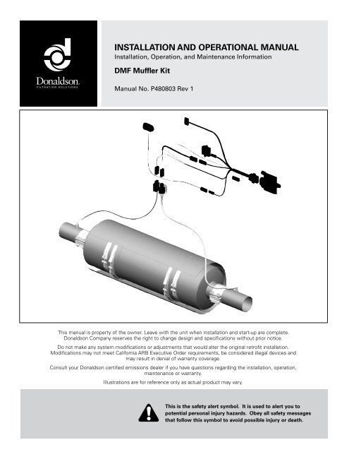
INSTALLATION AND OPERATIONAL MANUAL<br />
<strong>Installation</strong>, Operation, <strong>and</strong> Maintenance Information<br />
DMF Muffler Kit<br />
Manual No. P480803 Rev 1<br />
This <strong>manual</strong> is property of the owner. Leave with the unit when installation <strong>and</strong> start-up are complete.<br />
<strong>Donaldson</strong> <strong>Company</strong> reserves the right to change design <strong>and</strong> specifications without prior notice.<br />
Do not make any system modifications or adjustments that would alter the original retrofit installation.<br />
Modifications may not meet California ARB Executive Order requirements, be considered illegal devices <strong>and</strong><br />
may result in denial of warranty coverage.<br />
Consult your <strong>Donaldson</strong> certified emissions dealer if you have questions regarding the installation, operation,<br />
maintenance or warranty.<br />
Illustrations are for reference only as actual product may vary.<br />
This is the safety alert symbol. It is used to alert you to<br />
potential personal injury hazards. Obey all safety messages<br />
that follow this symbol to avoid possible injury or death.
2 <strong>Donaldson</strong> DMF Muffler Owners Manual - P480803 Rev 1
DMF Mufflers are passive catalytic mufflers designed to reduce diesel PM <strong>and</strong><br />
gaseous emissions. This <strong>manual</strong> includes pre-installation requirements, installation<br />
instructions, warranty activation procedures, <strong>and</strong> maintenance recommendations for<br />
the <strong>Donaldson</strong> DMF Muffler.<br />
DMF Muffler Application ......................4<br />
DMF Muffler Kit Illustration ..................4<br />
Introduction ...........................................5<br />
DMF Muffler Kit Contents ................................................5<br />
Pre-<strong>Installation</strong> Requirements ..............5<br />
DMF Muffler Pre-<strong>Installation</strong> ............................... 5<br />
Application Pre-Assessment .................................................... 5<br />
Fuel Requirement ........................................................................ 6<br />
Engine Lube Oil Requirement .................................................... 6<br />
Mounting Hardware Requirement ........................................... 6<br />
Weigh <strong>and</strong> Record Filter Section ............................................. 6<br />
EDM Pre-<strong>Installation</strong> ............................................. 7<br />
<strong>Installation</strong> .............................................7<br />
Vertical Muffler <strong>Installation</strong> ................................. 8<br />
Remove the Existing Muffler ..................................................... 8<br />
Install the DMF Muffler .............................................................. 8<br />
Install the Heat Shield on Muffler Body .................................. 8<br />
Attach DMF Muffler to Tubing .................................................. 9<br />
Operate Vehicle & Check for Leaks ......................................... 9<br />
Attach Engine Tags .................................................................... 9<br />
Install the EDM ........................................................................... 9<br />
Horizontal Muffler <strong>Installation</strong> ............................. 9<br />
Remove the Existing Muffler ..................................................... 9<br />
Install the DMF Muffler .............................................................. 9<br />
Install the Heat Shield on Muffler Body ................................ 10<br />
Attach DMF Muffler to Tubing ................................................ 11<br />
Operate Vehicle & Check for Leaks ....................................... 11<br />
Attach Engine Tags .................................................................. 11<br />
Install the EDM ......................................................................... 11<br />
<strong>Installation</strong> Checklist ......................................................11<br />
DMF Muffler ....................................................................11<br />
Emissions Device Monitor (EDM) ................................11<br />
Program Compliance .....................................................12<br />
Contents<br />
<strong>Donaldson</strong> Retrofit Emissions System<br />
Activate the Warranty ..........................12<br />
http://pwww.donaldson.com ........................................12<br />
Emissions Retrofit Documentation ..............................12<br />
Operation .............................................12<br />
Maintenance <strong>and</strong> Service ..................12<br />
DPF Section Service Records ......................................12<br />
Routine Inspections During Vehicle Service .............13<br />
Filter Cleaning . ...............................................................13<br />
Filter Disposal Information ...........................................13<br />
TroubleShooting ..............................................................14<br />
DMF Muffler Kit Limited Warranty ......15<br />
<strong>Donaldson</strong> DMF Muffler Owners Manual - P480803 Rev 1 3
<strong>Donaldson</strong> Retrofit Emissions System<br />
DMF Muffler Application<br />
DMF Mufflers that operate within California must be applied<br />
to vehicles in strict accordance with the vehicle <strong>and</strong> engine<br />
conditions published by California A.R.B Executive Order.<br />
Specific part numbers must be ordered to ensure that DECS<br />
tags are compliant with program requirements. DMF Muffler<br />
applications that operate in California but do not adhere to<br />
all the C.A.R.B requirements, including the installation of<br />
California-identified DECS tags, are considered illegal devices<br />
<strong>and</strong> may result in fines <strong>and</strong> possible denial of warranty<br />
coverage.<br />
DMF Muffler Kit<br />
Illustration<br />
Outlet<br />
Engine Tag<br />
(Serialized)<br />
Temperature<br />
Sensor<br />
Outlet Section<br />
Patent pending<br />
V-B<strong>and</strong><br />
Clamps (2x)<br />
In-Cab Display<br />
Muffler Tag<br />
(Serialized)<br />
Filter Section<br />
Heat Shield<br />
Heat Shield<br />
Clamps (2x)<br />
4 <strong>Donaldson</strong> DMF Muffler Owners Manual - P480803 Rev 1<br />
Applications outside of California should adhere to the same<br />
requirements unless program rules permit variations, the<br />
customers underst<strong>and</strong> <strong>and</strong> agree to exceptions, <strong>and</strong> <strong>Donaldson</strong><br />
accepts the technical <strong>and</strong> warranty risks associated with the<br />
application. Specific part numbers must be ordered to obtain<br />
non-California DECS tags for those applications.<br />
Inlet Section<br />
Wire Harness<br />
SealClamp<br />
B<strong>and</strong> Clamps<br />
(not supplied)<br />
Emissions Device Monitor (EDM)<br />
Monitors the backpressure <strong>and</strong> temperature of<br />
the system, <strong>and</strong> alerts the operator of engine<br />
malfunctions that affect device operation or<br />
device service requirements via the in-cab<br />
display.<br />
Backpressure<br />
Sensor<br />
Small Electronic<br />
Control Module<br />
(SECM)<br />
Inlet
Introduction<br />
<strong>Donaldson</strong>’s DMF Muffler is designed to reduce harmful<br />
emissions from in-use diesel engines. Besides reducing diesel<br />
particulate matter emissions up to 60%, the DMF muffler is<br />
also effective at reducing carbon monoxide <strong>and</strong> hydrocarbon<br />
emissions.<br />
The DMF Mufflers consist of an inlet, outlet <strong>and</strong> center body<br />
section with two metallic filters. Removable V-b<strong>and</strong> clamps<br />
provide easy access to the center body.<br />
The DMF Muffler Kit includes an Emissions Device Monitor<br />
(EDM) that detects excessive soot loading caused by<br />
insufficient temperature, engine maintenance issues, or engine<br />
component failure. The kit also includes shielding to protect<br />
heat sensitive components.<br />
DMF Mufflers are safe <strong>and</strong> reliable, easy to apply <strong>and</strong> provide<br />
substantial benefits in air quality.<br />
For optimum performance of your DMF Muffler, follow<br />
<strong>Donaldson</strong>’s simple installation requirements.<br />
CAUTION!<br />
Follow <strong>Donaldson</strong> <strong>Installation</strong><br />
Requirements<br />
<strong>Installation</strong>s must follow <strong>Donaldson</strong> installation<br />
requirements to ensure full warranty coverage. For optimum<br />
performance, follow all the installation, operation <strong>and</strong><br />
maintenance recommendations covered in this <strong>manual</strong>.<br />
DMF Muffler Kit Contents<br />
Qty. Description<br />
1 DMF Muffler Assembly<br />
1 Emissions Device Monitor (EDM) with installation <strong>and</strong> operation<br />
<strong>manual</strong>.<br />
1 Heat Shield<br />
2 Heat Shield mounting brackets<br />
1 Documentation package that includes this owner's <strong>manual</strong>,<br />
DMF Muffler Warranty, a warranty registration worksheet <strong>and</strong> a<br />
serialized metal Diesel Engine Control Strategy (DECS) engine tag .<br />
Additional components/tools for Heat Shield <strong>Installation</strong>:<br />
Bolts: Six 3/4” long 5/16”-18 bolts with lock washers (grade 5<br />
minimum) or self-locking serrated flange bolts<br />
Metal Cutter: For heat shield length modifications, a plasma cutter or<br />
cut-off wheel may be useful<br />
<strong>Donaldson</strong> Retrofit Emissions System<br />
Pre-<strong>Installation</strong> Requirements<br />
<strong>Donaldson</strong>’s pre-installation requirements are provided below.<br />
In order to maximize the diesel emission control system<br />
performance <strong>and</strong> life, the installation must meet these<br />
requirements. Failure to follow these instructions may void the<br />
warranty <strong>and</strong> could lead to device failure.<br />
DMF Muffler Pre-<strong>Installation</strong><br />
Application Pre-Assessment<br />
• Verify that the application PASSED the <strong>Donaldson</strong> Application<br />
Pre-assessment conducted by a Certified Emissions Dealer. The preassessment<br />
worksheet <strong>and</strong> opacity test results need to be forwarded<br />
to <strong>Donaldson</strong> upon warranty registration.<br />
• The application pre-assessment confirms the following:<br />
• The engine family number (EFN) for the vehicle is included in the California<br />
ARB-Approved Engine Family listing of Executive Order.<br />
• Vehicle <strong>and</strong> engine has been properly maintained<br />
• Vehicle passed the pre-assessment visual system inspection<br />
• Opacity test results collected meet requirements based on SAE J1667 test<br />
specification<br />
• Vehicle engine duty cycle meets the application temperature criteria.<br />
• Vehicles must be data logged prior to application of the<br />
<strong>Donaldson</strong> DMF Muffler Kit to ensure the engine duty cycle<br />
meets the application criteria. Follow <strong>Donaldson</strong> data logging<br />
requirements as specified in <strong>Donaldson</strong> Document Number<br />
P480348. Alternate data logging approaches may not provide<br />
an accurate picture of operating temperature <strong>and</strong> result in<br />
unsatisfactory operation. Contact <strong>Donaldson</strong> Engineering to<br />
review compatibility of data logging approaches.<br />
• Retain the <strong>Donaldson</strong> data logging response letter <strong>and</strong> data<br />
log to confirm compliance with application criteria. A copy<br />
of these documents will be required at the time of warranty<br />
registration should be kept in the vehicle as they may be<br />
requested by California ARB or other enforcement staff.<br />
• Only apply a DMF Muffler when approved by <strong>Donaldson</strong> or a<br />
<strong>Donaldson</strong> certified dealer in writing via a formal data logging<br />
response letter. Applying a DMF Muffler to a vehicle that<br />
does not meet exhaust gas temperature (EGT) criteria in the<br />
California ARB Executive Order would be an illegal device.<br />
• Be sure to plug the welded fitting where the thermocouple was<br />
installed after data logging to prevent emissions leakage.<br />
NOTE<br />
Engine Must Meet OEM<br />
Specifications<br />
The engine must be inspected by a qualified technician<br />
to verify the engine is operating within the engine OEM’s<br />
specifications. If the engine does not meet specifications,<br />
necessary repairs must be made prior to DMF Muffler<br />
installation. The technician must document compliance<br />
on the <strong>Donaldson</strong> warranty registration web site.<br />
<strong>Donaldson</strong> DMF Muffler Owners Manual - P480803 Rev 1 5
<strong>Donaldson</strong> Retrofit Emissions System<br />
Fuel Requirement<br />
DMF Mufflers require the use of ULSD Fuel (15 ppm or less<br />
sulfur content) that meets ASTM D975. B20 BioULSD (20%<br />
biodiesel/80% ULSD) that meets ASTM D6751 diesel fuel<br />
specifications may also be used. Fuel additives are not<br />
permitted <strong>and</strong> may void your warranty.<br />
Engine Lube Oil Requirement<br />
The DMF Mufflers require the use of engine lube oil that meets<br />
CJ-4 specifications (low ash).<br />
Mounting Hardware Requirement<br />
A DMF Muffler weighs considerably more than a traditional<br />
OEM truck muffler (70 lbs. vs. 30 lbs. [31.7 kg vs 13.6 kg]).<br />
Inspect any mounting system hardware intended for reuse to<br />
ensure it is in good condition <strong>and</strong> can adequately support the<br />
added weight. Look for signs of rust, corrosion or fatigue. Do<br />
not reuse suspect components. New heavy-duty<br />
components should be used.<br />
NOTE Inspect Mounting Hardware<br />
A DMF Muffler is more than two times heavier than a<br />
traditional OEM truck muffler. The mounting system should<br />
be inspected to ensure it is in good condition <strong>and</strong> can<br />
adequately support the added weight. Inspect all hardware<br />
intended for reuse for rust, corrosion or fatigue. Replace<br />
all questionable components with heavy-duty components.<br />
Isolation Requirements to Avoid Vibration<br />
The DMF Muffler must be isolated from engine vibration. Do<br />
not hard-mount the muffler assembly directly to the engine or<br />
install where the device can be subject to vehicle or equipment<br />
vibration.<br />
The DMF Muffler should be mounted as close to the engine<br />
as possible, but must be isolated from engine vibration. If not<br />
isolated properly, vibration may damage the exhaust system or<br />
the retrofit muffler.<br />
Exhaust Tubing Requirements<br />
The engine EGT has an affect on emissions performance. To<br />
optimize performance, the DMF Muffler inlet must be installed<br />
within 12 inches (305 mm) from where the temperature probe<br />
was installed during preliminary temperature data logging to<br />
6 <strong>Donaldson</strong> DMF Muffler Owners Manual - P480803 Rev 1<br />
ensure the EGT is representative of what the DMF Muffler will<br />
see. Minimize the distance from the turbo to the emissions<br />
device inlet.<br />
Mount the DMF Muffler within 6"<br />
NOTE<br />
(305mm) from temperature probe<br />
To optimize performance, the inlet on the new DMF must<br />
be installed within 6 inches (152.4 mm) from where the<br />
temperature probe was installed during preliminary data<br />
logging. Mounting the DMF Muffler beyond this distance<br />
may cause frequent cleaning intervals <strong>and</strong> may result in<br />
unsatisfactory / unreliable performance or plugging.<br />
To maximize effectiveness, exhaust tubing should be structurally<br />
sound <strong>and</strong> leak-free. Inspect the exhaust tubing for damage<br />
or corrosion, <strong>and</strong> replace defective components. Also look<br />
for flaking due to corrosion <strong>and</strong>/or soot build-up. Loose<br />
contaminants can be blown onto the DMF face <strong>and</strong> cause<br />
increased backpressure <strong>and</strong> degraded engine performance.<br />
Operate engine at high idle to blow out exhaust pipes prior to<br />
the installation of the emissions device.<br />
Rust, Corrosion <strong>and</strong> Soot on<br />
NOTE<br />
Existing Exhaust Tubing<br />
If you see any evidence of rust or corrosion on existing<br />
tubing between the turbocharger <strong>and</strong> DMF Muffler inlet,<br />
replace with new aluminized steel tubing. If reusing<br />
existing exhaust tubing, banging <strong>and</strong> tapping on the tubing<br />
may dislodge soot. Be sure to clean out any pipes prior to<br />
installing new components. Operate engine at high idle<br />
to blow out exhaust pipes prior to the installation of the<br />
emissions device. Protect yourself <strong>and</strong> others from loud<br />
noise <strong>and</strong> flying debris.<br />
CAUTION! Do Not Overtighten<br />
B<strong>and</strong>s or Clamps on Muffler Center<br />
Body<br />
The filters inside the DMF center section could be damaged<br />
if you deform the muffler body by overtightening clamps.<br />
Weigh <strong>and</strong> Record Filter Section<br />
If you plan to use the weight of the filter as a basis to determine<br />
the cleanliness of the filter after cleaning, it is recommended<br />
that you weigh the new filter section prior to installation or use.<br />
NOTE Weighing the Filter Section<br />
Proper filter weight measurements require removal of the<br />
filter section from the muffler assembly <strong>and</strong> a scale with<br />
at least 1.0 gram solution.
EDM Pre-<strong>Installation</strong><br />
The EDM has a separate installation, operation <strong>and</strong><br />
maintenance <strong>manual</strong> (P484891) <strong>and</strong> is packaged with the EDM<br />
components.<br />
Temp Alarm<br />
In-Cabin Display<br />
Service Soon<br />
Service Now<br />
Mounting Location - SECM<br />
• Mount the SECM in a place at or near the fuse panel.<br />
• Look for a keyed power source on the fuse panel.<br />
• Try to locate the SECM in the driver's cab; the engine cabin is a<br />
secondary choice. The SECM needs to be located within 5 feet of<br />
where the In-Cab Display will be mounted.<br />
COMS Connection - Position for Easy Access<br />
• A technician will need to access the connector labeled "COMS"<br />
when the DMF Muffler is serviced or cleaned. Make sure the COMS<br />
connector is easy to access.<br />
• If retrofitting several vehicles in a fleet, consider positioning the COMS<br />
connector in the same general area so the technicians can locate it<br />
easily.<br />
Rear Engine <strong>Installation</strong>s<br />
• If installing the EDM on a rear engine vehicle, you will need to order<br />
the 50 foot sensor harness (P231739) separately to reach the sensors.<br />
Install<br />
Tip<br />
Save Install Time<br />
To minimize your installation time, consider using selfdrilling<br />
screws to mount the SECM <strong>and</strong> sensor mounting<br />
bracket.<br />
<strong>Installation</strong><br />
<strong>Donaldson</strong> Retrofit Emissions System<br />
The following section includes separate procedures for vertical<br />
<strong>and</strong> horizontal installations. Please use the procedure that<br />
matches your intended muffler orientation.<br />
Before proceeding with installation, the vehicle must PASS<br />
the application pre-assessment worksheet <strong>and</strong> data log<br />
requirements.<br />
If poor vehicle maintenance practices are known, engine<br />
problems must be resolved prior to installation. Improper<br />
maintenance or lack of maintenance may cause DMF Muffler<br />
filter plugging or failure.<br />
CAUTION! Vehicle Must Meet<br />
Temperature Criteria!<br />
Data log vehicles during normal operation to ensure the duty<br />
cycle meets the device temperature requirements. Minimize<br />
low-load conditions or idling for extended periods of time or<br />
plugging may occur.<br />
Engine Problems Must be<br />
NOTE Resolved PRIOR to Installing<br />
the DMF Muffler<br />
DMF Mufflers may plug if the engine is not properly<br />
maintained. To prevent the occurrence of plugging, engine<br />
problems must be resolved prior to installing the DMF<br />
Muffler. Ensure the engine meets OEM specs.<br />
Install<br />
Tip<br />
Save Install Time if Disposing of<br />
the Old Muffler <strong>and</strong> Components<br />
It's not a good idea to reuse old exhaust components on<br />
new retrofit emission installations. So, if your installation<br />
plan is to discard the old components, reduce install time<br />
by using a Sawzall to cut the muffler <strong>and</strong> old clamps out<br />
of the exhaust system.<br />
<strong>Donaldson</strong> DMF Muffler Owners Manual - P480803 Rev 1 7
<strong>Donaldson</strong> Retrofit Emissions System<br />
Vertical Muffler<br />
<strong>Installation</strong><br />
Remove the Existing<br />
Muffler<br />
1. Loosen stack clamp at<br />
muffler outlet (top). Remove<br />
stack <strong>and</strong> clamp.<br />
2. Loosen tubing clamp at<br />
muffler inlet (bottom).<br />
3. Loosen clamps on flex<br />
tubing. Remove clamps, flex<br />
<strong>and</strong> elbow.<br />
4. Remove heat shield<br />
mounting brackets.<br />
5. Loosen muffler <strong>and</strong> remove.<br />
Dispose of or recycle old<br />
muffler.<br />
Install the DMF Muffler<br />
1. Inspect the mounting brackets, b<strong>and</strong>s, supports <strong>and</strong>/or stanchion<br />
for any damage, cracks or corrosion. Replace any existing<br />
mounting parts that appear rusted, damaged or of questionable<br />
strength with heavy-duty parts. Mounting components must be<br />
strong enough to support the DMF Muffler, which weighs roughly<br />
70 lbs. (31.7 kgs). <strong>Donaldson</strong> offers many components designed<br />
specifically to h<strong>and</strong>le the added weight of emissions retrofit<br />
devices.<br />
2. Ensure the DMF Muffler is installed so that flow arrows match the<br />
exhaust flow direction. The directional arrow on the DMF section<br />
should be facing towards the outlet. The outlet end typically has<br />
a convex baffle to permit water drainage (exception outlet section<br />
with side tube).<br />
3. Place muffler/heat shield mounting brackets around the DMF<br />
Muffler body <strong>and</strong> finger-tighten. Rotate DMF Muffler so emissions<br />
device tag is visible. Tighten (snug fit) mounting bracket bolts to<br />
hold the DMF Muffler in place.<br />
CAUTION! Do Not Overtighten<br />
B<strong>and</strong>s or Clamps on Muffler Body<br />
The filters inside the DMF center section could be damaged<br />
if you deform the muffler body by overtightening clamps.<br />
Install the Heat Shield on Muffler Body<br />
S<br />
t<br />
a<br />
n<br />
c<br />
h<br />
i<br />
o<br />
n<br />
Clamp<br />
Clamp<br />
Mounting Bracket<br />
V-b<strong>and</strong> Clamps (2x)<br />
Mounting Bracket<br />
CAUTION! Shield Heat Sensitive<br />
Components!<br />
The heat shield must be installed 1.5" away from heatsensitive<br />
components. Failure to do so may degrade<br />
surrounding components <strong>and</strong> structure in the event of high<br />
temperatures.<br />
8 <strong>Donaldson</strong> DMF Muffler Owners Manual - P480803 Rev 1<br />
NOTE<br />
Allow Adequate Clearance with<br />
Existing Components<br />
If the heat shield is coming in contact with any pre-existing<br />
vehicle components, the DMF will need to be repositioned to<br />
allow adequate clearance for the muffler guard.<br />
The slit in the heat shield is only there to allow the DMF Muffler<br />
mounting b<strong>and</strong>s to protrude for attachment. Ensure all existing<br />
vehicle components are still spaced at least 1.5” away from the<br />
DMF Muffler body in the uncovered area.<br />
1. Loosen the DMF Muffler v-b<strong>and</strong> clamps <strong>and</strong> rotate them until the<br />
pinch bolt is aligned with the DMF’s mounting bracket st<strong>and</strong>-off or<br />
W-foot. This will prevent contact of the pinch bolt with the heat<br />
shield.<br />
2. Retighten the v-b<strong>and</strong> clamps <strong>and</strong> torque 200 in-lbs.<br />
3. Place the heat shield on the DMF muffler with the open slit in the<br />
shield aligned with the DMF Muffler’s mounting bracket st<strong>and</strong>-offs<br />
<strong>and</strong> center it on the DMF muffler.<br />
Open section toward<br />
mounting frame<br />
The open side of the heat shield should align with the muffler<br />
mounting frame.<br />
4. While positioned in place, mark the heat shield for areas that need<br />
to be modified.<br />
a. If there is a side inlet or outlet, mark the location so a notch<br />
can be cut for it.<br />
b. The heat shield may also come into contact with the DMF<br />
muffler mounting clamp at the pinch bolt location. Mark the<br />
heat shield <strong>and</strong> cut a small opening if necessary.<br />
c. Notice the pre-drilled mounting holes in the heat shield (22”<br />
apart). Note or mark where the heat shield mounting b<strong>and</strong>s<br />
should be installed on the DMF muffler.<br />
d. If the existing DMF muffler mounting b<strong>and</strong>s prevent installing<br />
the heat shield mounting b<strong>and</strong>s, the heat shield mounting<br />
b<strong>and</strong>s may be located elsewhere on the DMF muffler <strong>and</strong> new<br />
holes can be drilled in the heat shield.<br />
5. Remove the heat shield <strong>and</strong> modify it to fit around the DMF<br />
muffler. A plasma cutter or cut-off wheel may be useful for these<br />
modifications. A 3/8” bit can be used if new mounting holes are<br />
needed (6 holes).<br />
6. Remove the allen head bolts from the heat shield clamps. Note:<br />
the trunniuns will fall out. Be careful not to lose them.<br />
7. Mount the heat shield mounting b<strong>and</strong>s to the DMF muffler where<br />
previously decided <strong>and</strong> torque to 5 ft-lbs.
8. Place the heat shield on the DMF muffler, align with the heat shield<br />
mounting b<strong>and</strong>s <strong>and</strong> install either six 3/4” long 5/16”-18 bolts with<br />
lock washers (grade 5 minimum) or six self-locking serrated flange<br />
bolts in through the heat shield. Torque bolts to 5 ft-lbs.<br />
9. Make sure the heat shield is not rubbing any vehicle components<br />
<strong>and</strong> is centered on the DMF muffler.<br />
Attach DMF Muffler to Tubing<br />
1. Position flex tubing <strong>and</strong> clamps (i.e., SealClamp®) onto exhaust<br />
tube. Do not tighten clamps until all tubing is assembled.<br />
NOTE<br />
Flex is not approved in all<br />
locations. Check local ordinances<br />
or retrofit program rules.<br />
2. Position inlet elbow <strong>and</strong> muffler inlet clamp. Locate flex tube so<br />
that there are equal lengths of rigid tubing (within the flex) on both<br />
ends. Tighten clamps to secure flex tubing <strong>and</strong> inlet elbow to the<br />
emissions device inlet section.<br />
Avoid Excessive Force on Inlet <strong>and</strong><br />
NOTE<br />
Outlet Piping!<br />
Excessive force on the inlet <strong>and</strong> outlet piping in conjunction<br />
with vehicle vibration can result in stress cracking on the pipe<br />
or the emissions device inlet. Failures caused by excessive<br />
force are a result of improper installation <strong>and</strong> are not covered<br />
by warranty.<br />
3. Position clamp over outlet tube on the DMF Muffler outlet section.<br />
Insert the stack into the muffler outlet <strong>and</strong> tighten securely. Install a<br />
curved outlet stack or rain cap to a straight stack.<br />
Water from Rain <strong>and</strong> Truck Washing<br />
NOTE<br />
Can Damage or Deactivate the Filter<br />
Vertical tail pipes must be fitted with rain caps or curved<br />
outlets.<br />
4. Verify that all bolts <strong>and</strong> fasteners have been sufficiently tightened.<br />
Operate Vehicle & Check for Leaks<br />
1. Operate vehicle <strong>and</strong> check for exhaust leaks. Repair any leaks.<br />
2. Turn off the engine.<br />
Attach Engine Tags<br />
Permanently attach the DECS engine tag (supplied in documentation package)<br />
onto the engine using high-temp RTV or a screw. Regulations require the<br />
DECS engine tag be installed in a location clearly visible to Enforcement staff.<br />
Application of the engine tag is m<strong>and</strong>atory in California, <strong>and</strong> recommended<br />
outside of California (for U.S. EPA programs).<br />
<strong>Donaldson</strong> Retrofit Emissions System<br />
Permanently affix DECS<br />
NOTE<br />
Engine Tag onto Engine<br />
California ARB regulations require a DECS engine tag<br />
be permanently installed on the engine in a clear, visible<br />
location. Use high-temp RTV or screw.<br />
Install the EDM<br />
Install Emissions Device Monitor (EDM). <strong>Installation</strong> instructions are included<br />
with the monitor (<strong>manual</strong> P484891).<br />
Horizontal Muffler <strong>Installation</strong><br />
Remove the Existing Muffler<br />
Install<br />
Tip<br />
Save Install Time. Use a Come-<br />
Along Winch to Remove Muffler<br />
On horizontal muffler installations, a come-along winch can<br />
be used to pull the OEM outlet piping back far enough to<br />
remove the existing muffler. This same tool is also helpful<br />
when installing the new DMF Muffler.<br />
1. Loosen clamp at muffler outlet. Remove clamp <strong>and</strong> tailpipe.<br />
2. Remove clamp at muffler inlet.<br />
3. Loosen muffler mounting bracket <strong>and</strong> remove muffler.<br />
4. Dispose of or recycle old muffler.<br />
Install the DMF Muffler<br />
Clamp<br />
«<br />
Mounting<br />
Bracket<br />
«<br />
Frame Rail<br />
V-b<strong>and</strong><br />
Clamps (2x)<br />
Clamp<br />
<strong>Donaldson</strong> DMF Muffler Owners Manual - P480803 Rev 1 9<br />
«<br />
«<br />
Mounting<br />
Bracket<br />
1. Inspect the mounting brackets, b<strong>and</strong>s, supports <strong>and</strong>/or frame rail<br />
for any damage, cracks or corrosion. Mounting components must<br />
be strong enough to adequately support the DMF Muffler which<br />
weighs roughly 70 lbs. (31.7 kgs). Replace any existing mounting<br />
parts that appear rusted, damaged or of questionable strength with<br />
heavy-duty parts. <strong>Donaldson</strong> offers many components designed<br />
specifically to h<strong>and</strong>le the added weight of emissions retrofit<br />
devices.<br />
CAUTION!<br />
Avoid Rigid Mounting of the<br />
New Emissions Device.<br />
The original equipment muffler should have flexible<br />
hangers installed to allow for thermal expansion. If<br />
your system does not have flexible hangers, appropriate<br />
hangers should be used.
<strong>Donaldson</strong> Retrofit Emissions System<br />
2. On vehicles with a vertical tailpipe, drill a 1/4" (6mm) drain hole 6"<br />
(152 mm) from the outlet end of the DMF Muffler. Install a curved<br />
outlet stack or rain cap to a straight stack.<br />
Drain Hole Required on Horizontal<br />
NOTE Mount Mufflers with Vertical<br />
Tailpipe(s)<br />
Horizontally-mounted mufflers with vertical tailpipe<br />
systems must have a 0.25" (6mm) diameter drain hole<br />
drilled through the lowest point of the emissions device<br />
outlet section 6" (152mm). Rain <strong>and</strong> truck wash water<br />
can deactivate or damage the filter, reducing emission<br />
performance. Install a curved outlet stack or rain cap to<br />
a straight stack. Damaged caused by water may result in<br />
denial of warranty coverage.<br />
3. Verify the muffler is being installed correctly. The directional arrow<br />
on the DMF section should be facing towards the outlet.<br />
4. Install mounting brackets over the DMF Muffler inlet/outlet sections<br />
<strong>and</strong> finger tighten. Position the drain hole at the bottom <strong>and</strong> mount<br />
in position. Be sure the mounting brackets do not cover the drain<br />
hole. Rotate muffler so CARB emissions device tag is visible.<br />
Ensure the DMF Muffler is installed so that flow arrows match the<br />
exhaust flow direction. Tighten (snug fit) mounting b<strong>and</strong>s bolts to<br />
hold the emissions device in place.<br />
5. Install the inlet piping to the DMF Muffler inlet section <strong>and</strong> tighten<br />
the clamp (i.e., SealClamp). Ensure the DMF Muffler is installed so<br />
that flow arrows match the exhaust flow direction.<br />
CAUTION! Do Not Overtighten<br />
Brackets or Clamps on the<br />
Muffler Center Body<br />
The filters inside the DMF center section could be damaged<br />
if you deform the muffler body by overtightening clamps.<br />
Install the Heat Shield on Muffler Body<br />
CAUTION! Shield Heat Sensitive<br />
Components!<br />
The heat shield must be installed 1.5" away from heatsensitive<br />
components. Failure to do so may degrade<br />
surrounding components <strong>and</strong> structure in the event of high<br />
temperatures.<br />
NOTE<br />
Allow Adequate Clearance with<br />
Existing Components<br />
If the heat shield is coming in contact with any pre-existing<br />
vehicle components, the DMF will need to be repositioned to<br />
allow adequate clearance for the muffler guard.<br />
The slit in the heat shield is only there to allow the DMF Muffler<br />
mounting b<strong>and</strong>s to protrude for attachment. Ensure all existing<br />
vehicle components are still spaced at least 1.5” away from the<br />
DMF muffler body in the uncovered area.<br />
10 <strong>Donaldson</strong> DMF Muffler Owners Manual - P480803 Rev 1<br />
1. Loosen the DMF Muffler v-b<strong>and</strong> clamps <strong>and</strong> rotate them until the<br />
pinch bolt is aligned with the DMF’s mounting bracket st<strong>and</strong>-off or<br />
W-foot. This will prevent contact of the pinch bolt with the heat<br />
shield.<br />
2. Retighten the v-b<strong>and</strong> clamps <strong>and</strong> torque 200 in-lbs.<br />
3. Place the heat shield on the DMF muffler with the open slit in the<br />
shield aligned with the DMF Muffler’s mounting bracket st<strong>and</strong>-offs<br />
<strong>and</strong> center it on the DMF muffler.<br />
Open section toward<br />
mounting frame<br />
The open side of the heat shield should align with the muffler<br />
mounting frame.<br />
4. While positioned in place, mark the heat shield for areas that need<br />
to be modified.<br />
a. If there is a side inlet or outlet, mark the location so a notch<br />
can be cut for it.<br />
b. The heat shield may also come into contact with the DMF<br />
muffler mounting clamp at the pinch bolt location. Mark the<br />
heat shield <strong>and</strong> cut a small opening if necessary.<br />
c. Notice the pre-drilled mounting holes in the heat shield (22”<br />
apart). Note or mark where the heat shield mounting b<strong>and</strong>s<br />
should be installed on the DMF muffler.<br />
d. If the existing DMF muffler mounting b<strong>and</strong>s prevent installing<br />
the heat shield mounting b<strong>and</strong>s, the heat shield mounting<br />
b<strong>and</strong>s may be located elsewhere on the DMF muffler <strong>and</strong> new<br />
holes can be drilled in the heat shield.<br />
5. Remove the heat shield <strong>and</strong> modify it to fit around the DMF<br />
muffler. A plasma cutter or cut-off wheel may be useful for these<br />
modifications. A 3/8” bit can be used if new mounting holes are<br />
needed (6 holes).<br />
6. Remove the allen head bolts from the heat shield clamps. Note:<br />
the trunniuns will fall out. Be careful not to lose them.<br />
7. Mount the heat shield mounting b<strong>and</strong>s to the DMF muffler where<br />
previously decided <strong>and</strong> torque to 5 ft-lbs.<br />
8. Place the heat shield on the DMF muffler, align with the heat shield<br />
mounting b<strong>and</strong>s <strong>and</strong> install either six 3/4” long 5/16”-18 bolts with<br />
lock washers (grade 5 minimum) or six self-locking serrated flange<br />
bolts in through the heat shield. Torque bolts to 5 ft-lbs.<br />
9. Make sure the heat shield is not rubbing any vehicle components<br />
<strong>and</strong> is centered on the DMF muffler.
Attach DMF Muffler to Tubing<br />
1. Install tailpipe <strong>and</strong> secure clamp (i.e., SealClamp) on emissions<br />
device outlet section.<br />
2. Verify that all bolts <strong>and</strong> fasteners have been sufficiently tightened.<br />
Operate Vehicle & Check for Leaks<br />
1. Operate vehicle <strong>and</strong> check for exhaust leaks. Repair any leaks.<br />
2. Turn off the engine.<br />
Attach Engine Tags<br />
Permanently attach the DECS engine tag (supplied in<br />
documentation package) onto the engine using high-temp RTV<br />
or a screw. CARB regulations require the DECS engine tag be<br />
installed in a location clearly visible to Enforcement staff.<br />
Application of the engine tag is m<strong>and</strong>atory in California, <strong>and</strong><br />
recommended outside of California (for U.S. EPA programs).<br />
Permanently affix DECS<br />
NOTE<br />
Engine Tag onto Engine<br />
California ARB regulations require a DECS engine tag<br />
be permanently installed on the engine in a clear, visible<br />
location. Use high-temp RTV or screw.<br />
Install the EDM<br />
Install Emissions Device Monitor (EDM). <strong>Installation</strong><br />
instructions will be included with the monitor (<strong>manual</strong><br />
P484891).<br />
<strong>Installation</strong> Checklist<br />
DMF Muffler<br />
<strong>Donaldson</strong> Retrofit Emissions System<br />
❏ DMF Muffler mounted in proper exhaust flow<br />
direction<br />
❏ All DMF Muffler mounting hardware <strong>and</strong> clamps<br />
are tightened.<br />
❏ Heat shield installed to protect sensitive<br />
components (1.5" clearance)<br />
❏ New hardware <strong>and</strong> clamps installed per this<br />
<strong>manual</strong> or CHP drawing (school bus only)<br />
❏ No visible exhaust leaks in the system<br />
Emissions Device Monitor (EDM)<br />
❏ No dips, kinks or low spots in stainless steel<br />
braided hose (must have an uphill path to pressure<br />
transducer to avoid water damage)<br />
❏ Pressure transducer threaded barb points<br />
downward to prevent water damage<br />
❏ Temperature probe wire secured at least 6” (152<br />
mm) away from hot exhaust pipes<br />
❏ In-Cab Display mounted in sight of the vehicle<br />
operator<br />
❏ COMS connection on wiring harness mounted<br />
in a location that can be easily accessed by the<br />
mechanic<br />
❏ All wiring harnesses secure at least 6” (152 mm)<br />
away from high heat <strong>and</strong> moving parts<br />
❏ All connectors mated securely<br />
❏ Memory module plugged in<br />
❏ 12V DC, 10A fuse-protected, keyed power<br />
attached <strong>and</strong> grounded<br />
❏ Any wires mounted through holes must have hole<br />
edges protected by a grommet<br />
❏ Wires should be protected in looms<br />
❏ Wiring between two members where relative<br />
motion can occur should be secured to each<br />
member <strong>and</strong> have enough slack to allow motion<br />
without damage to the wire.<br />
❏ At key-up, all three LED lights on the In-Cab<br />
display blink for three seconds<br />
<strong>Donaldson</strong> DMF Muffler Owners Manual - P480803 Rev 1 11
<strong>Donaldson</strong> Retrofit Emissions System<br />
❏ Vehicle operators trained on new In-Cab Display<br />
<strong>and</strong> alerts<br />
❏ Complete Vehicle Setup: Connect laptop with<br />
COMS port <strong>and</strong> enter information into SECM<br />
“Vehicle Setup” (VIN, Diesel Emission Control<br />
Strategy [DECS] Serial No., install date, etc.)<br />
Program Compliance<br />
❏ ARB engine tag permanently affixed to the engine<br />
with RTV silicone in a visible location<br />
❏ End user has warranty document, preassessment<br />
worksheet, temperature data log,<br />
<strong>Donaldson</strong> response letter <strong>and</strong> this <strong>manual</strong> for<br />
their records.<br />
❏ Warranty activated <strong>and</strong> documentation submitted<br />
to <strong>Donaldson</strong> on http://pwww.donaldson.com<br />
Activate the Warranty<br />
For regulatory reporting <strong>and</strong> warranty registration purposes,<br />
<strong>Donaldson</strong> <strong>Company</strong> requires the installer/dealer to complete<br />
<strong>and</strong> submit the warranty for the vehicle or equipment owner on<br />
our web site at http://pwww.donaldson.com.<br />
Supporting documents are also required at time of Registering:<br />
The warranty registration web site requires that you upload the<br />
(1) Application Pre-assessment Worksheet (F114050), <strong>and</strong> the<br />
(2) Opacity Test <strong>and</strong> (3) Data Logging results for the vehicle/<br />
equipment being registered.<br />
A Warranty Registration Worksheet is included in the<br />
documentation packet Register the new installation within 30<br />
days using our on-line warranty registration site at:<br />
http://pwww.donaldson.com<br />
Emissions Retrofit Documentation<br />
Retain all emissions retrofit documentation on each vehicle;<br />
including<br />
• Application pre-assessment worksheet from dealer including opacity<br />
test results <strong>and</strong> temperature data logging<br />
• <strong>Donaldson</strong> (or dealer) response letter that approved the<br />
retrofit application with signatures<br />
• Date of installation<br />
• Mileage / hours at install<br />
• <strong>Installation</strong> <strong>and</strong> owner information<br />
• Part number<br />
• Serial number<br />
• Service <strong>and</strong> cleaning records<br />
12 <strong>Donaldson</strong> DMF Muffler Owners Manual - P480803 Rev 1<br />
Operation<br />
<strong>Donaldson</strong> DMF Mufflers are designed <strong>and</strong> verified for use on<br />
on-road medium- <strong>and</strong> heavy-duty truck <strong>and</strong> bus applications.<br />
To ensure proper functioning of these products, the <strong>Donaldson</strong><br />
preventive maintenance <strong>and</strong> service procedures must be<br />
incorporated into your regular vehicle maintenance routines.<br />
The EDM monitors the backpressure <strong>and</strong> temperature of the<br />
system, <strong>and</strong> alerts the operator of engine malfunctions that<br />
affect device operation or device service requirements via the<br />
In-Cab Display. The SERVICE SOON light alerts the operator<br />
that a cleaning will be necessary in the coming week. The<br />
SERVICE NOW light indicates that a cleaning is necessary<br />
within 8 hours of operation or before the next work shift,<br />
whichever comes first.<br />
NOTE<br />
See EDM Manual for details on the<br />
In-Cab Display Alerts & Actions<br />
The information below is an<br />
excerpt from the <strong>manual</strong>.<br />
To ensure proper functioning of these products, <strong>Donaldson</strong><br />
preventative maintenance <strong>and</strong> service procedures must be<br />
incorporated into your regular vehicle maintenance routines.<br />
Maintenance <strong>and</strong> Service<br />
DPF Section Service Records<br />
<strong>Donaldson</strong> requires that the accurate <strong>and</strong> thorough records<br />
be maintained of any service <strong>and</strong> cleaning performed on your<br />
DMF Muffler.<br />
CAUTION! Maintain Proper<br />
Maintenance Records!<br />
<strong>Donaldson</strong> DMF Mufflers are regulated emission<br />
control devices. Failure to show accurate <strong>and</strong><br />
thorough service records upon request of regulator<br />
agency compliance inspections may result in<br />
warnings, fines or vehicle shut-down.<br />
To ensure compliance, the end-user is required to maintain<br />
the following information at the completion of any service<br />
occurrence:<br />
• Date <strong>and</strong> mileage <strong>and</strong>/or hours if or when the filter<br />
section is cleaned or service in any manner<br />
• DECS serial number<br />
• DMF Muffler Kit number
Routine Inspections During Vehicle Service<br />
The following preventive maintenance recommendations<br />
should be conducted during normally scheduled vehicle<br />
maintenance.<br />
1. Inspect the emissions device, exhaust piping <strong>and</strong> mounting<br />
brackets.<br />
2. Look for leaks, structural failures (cracks) <strong>and</strong> loose or missing<br />
fasteners.<br />
3. Repair or replace defective parts, as appropriate.<br />
CAUTION! Do Not Use Fuels<br />
Blended with Lube Oil or Additives<br />
Engine oil must not be blended with the engine's fuel.<br />
Fuel blended with oil may cause deposits in the filter that<br />
increase backpressure, reduce engine performance <strong>and</strong><br />
may result in denial of warranty coverage. The use of<br />
an unapproved additive may result in denial of warranty<br />
coverage.<br />
CAUTION! Do Not Modify Engines<br />
Electronically controlled engines are certified with a<br />
specific fuel <strong>and</strong> electronic program based on engine<br />
configuration <strong>and</strong> model year. Use only the fuel <strong>and</strong><br />
electronic program specified for your engine. Using the<br />
incorrect fuel <strong>and</strong>/or electronic program may cause<br />
excessive soot generation <strong>and</strong> DPF plugging <strong>and</strong> may<br />
result in denial of warranty coverage.<br />
CAUTION!<br />
Monitor Lube Oil Consumption<br />
Certain components found in engine lube oil can poison<br />
catalysts. To protect against filter failure <strong>and</strong>/or plugging,<br />
ensure that the engine is not consuming oil at a rate higher<br />
than specified by the engine manufacturer. Use low ash oils<br />
(CJ-4). Do not use fuel blended with lube oil. Fuel additives<br />
may not be used without written approval from <strong>Donaldson</strong>.<br />
The use of an unapproved additive may result in denial of<br />
warranty coverage.<br />
<strong>Donaldson</strong> Retrofit Emissions System<br />
Filter Cleaning<br />
The filtering device is located in the center body of the DMF<br />
Muffler. Filter plugging is uncommon, but can occur via excess<br />
soot loading caused by insufficient temperature, engine<br />
maintenance issues or engine component failures. If cleaning<br />
is required, contact <strong>Donaldson</strong> for filter cleaning instructions.<br />
NOTE No Routine Ash Cleaning<br />
The DMF Muffler does not typically require or need<br />
routine service during its life. Service will only be<br />
needed if it is misapplied or poor engine conditions<br />
increase soot output to an abnormally high level. If<br />
cleaning is required, contact <strong>Donaldson</strong> for instructions.<br />
Filter Disposal Information<br />
The filter section in the DMF Muffler contains precious metal<br />
catalyst to reduce carbon monoxide, hydrocarbons <strong>and</strong> diesel<br />
particulate matter emissions. Typical metals may include<br />
platinum, palladium <strong>and</strong> rhodium. These materials can be<br />
recycled from damaged or deactivated DMF Mufflers. Please<br />
dispose of DMF Mufflers in accordance with local regulations<br />
<strong>and</strong> laws; recycle when possible.<br />
<strong>Donaldson</strong> DMF Muffler Owners Manual - P480803 Rev 1 13
<strong>Donaldson</strong> Retrofit Emissions System<br />
TroubleShooting<br />
Issue Problem Corrective Actions<br />
Frequent DMF service needed<br />
as indicated by the EDM<br />
Soot coming out of tailpipe or<br />
on outlet of DMF Filter<br />
Soot leaking around V-b<strong>and</strong><br />
clamps<br />
Soot leaking at an external<br />
weld<br />
Misapplication Verify engine family number versus the approved<br />
Executive Order requirements<br />
Verify engine exhaust flow rate versus DMF sizing in<br />
sales brochure/parts listing<br />
Verify the use of ASTM certified ULSD with NO<br />
additives<br />
Verify the use of CJ-4 oil<br />
Duty Cycle/Temperature Check the preliminary data log<br />
Duty cycle may have changed, if so re-data log<br />
Change (or rotate) the vehicle onto tougher duty<br />
cycles with another vehicle.<br />
Excessive idling Ensure the driver is using anti-idling techniques<br />
<strong>Installation</strong> Check all exhaust piping <strong>and</strong> connections for possible<br />
obstructions<br />
Inspect DMF face for possible debris blocking the face<br />
False EDM light Verify the pressure sensor <strong>and</strong> line are installed<br />
correctly with no dips per the "install checklist".<br />
Troubleshoot EDM<br />
Download backpressure history to check legitimacy<br />
of light<br />
Ineffective cleaning Clean using the <strong>Donaldson</strong> recommended cleaning<br />
process<br />
Engine issues causing high soot<br />
output<br />
14 <strong>Donaldson</strong> DMF Muffler Owners Manual - P480803 Rev 1<br />
Check with OEM for most up to date ECU flashes<br />
Check fuel injectors for fuel or oil leaks. Ensure fuel<br />
system meets OEM specifications.<br />
Check air filter for excessive plugging or restriction<br />
Check turbocharger for damage or wear<br />
Check fuel pressure to ensure it is in spec<br />
Check injector timing to ensure it is in spec<br />
Check turbocharger seals for oil leaks into the intake<br />
or exhaust stream<br />
Check for worn piston rings<br />
Check valve seats, guides <strong>and</strong> seals for leaks or wear<br />
Damaged DMF Filter If DMF Filter outlet is soot covered, the DMF may have<br />
internal damage <strong>and</strong> should be inspected. Contact<br />
your certified emissions dealer for support.<br />
<strong>Inc</strong>omplete inner weld If the soot is highly concentrated on the inner wall of<br />
the outlet section, an internal weld is leaking. Submit a<br />
warranty claim through <strong>Donaldson</strong>.<br />
V-b<strong>and</strong> clamp loose Re-torque v-b<strong>and</strong> clamp to 200 in-lbs. <strong>and</strong> tap with a<br />
soft hammer around the installed clamp<br />
Flange damaged Inspect flange perimeter for dents or irregularities <strong>and</strong><br />
correct or replace defective part(s)<br />
Pinhole leak in weld Close pinhole using a MIG welder<br />
Replace defective components
Actions <strong>and</strong> Improper Maintenance That May Result<br />
in Denial of Your Warranty Coverage<br />
Prior to installing any DMF Muffler unit, a vehicle profile<br />
sheet must be completed by the equipment owner <strong>and</strong><br />
approved by <strong>Donaldson</strong>. Failure to obtain this approval may<br />
void this warranty.<br />
The following conditions are considered to be abuse,<br />
neglect or improper maintenance that may result in denial of<br />
warranty coverage:<br />
• Failure to follow Engine Original Equipment<br />
Manufacturer (OEM) maintenance <strong>and</strong> operating<br />
procedures. Proper maintenance <strong>and</strong> operating<br />
procedures are understood to be those procedures<br />
recommended by the OEM to ensure engine longevity<br />
<strong>and</strong> proper operation.<br />
• Excessive particulate emissions due to poor engine<br />
operation <strong>and</strong> maintenance.<br />
• Misapplication to an engine model or to a duty cycle<br />
other than that which it is designed <strong>and</strong> approved.<br />
• Improper installation (strict adherence to the<br />
<strong>Donaldson</strong> owners <strong>manual</strong> is required).<br />
• Alterations or attempted repairs.<br />
• Progressive engine failure that allows lube oil, fuel<br />
or coolant to be present in the engine exhaust, in<br />
excess of OEM specifications.<br />
Use of fuel:<br />
(a) other than that for which the engine is calibrated<br />
or other than recommended by <strong>Donaldson</strong>.<br />
(b) containing other than ultra low sulfur diesel or not<br />
approved in writing by <strong>Donaldson</strong>, or fuel other<br />
than that which is specifically required to achieve<br />
the emissions required.<br />
(c) blended fuel with lube oil, kerosene, fuel additives<br />
or other materials not approved in writing by<br />
<strong>Donaldson</strong>.<br />
• Excessive lube oil consumption.<br />
• Physical damage caused by misuse, abuse or road<br />
hazards including (but not limited to) dents, cuts or<br />
fractures.<br />
• Damage caused by improper cleaning procedures<br />
(failure to adhere to <strong>Donaldson</strong> recommended<br />
cleaning guidelines).<br />
• Failures or damage caused by mounting system<br />
failures.<br />
• Damage to the filter section or plugging caused by<br />
water entry.<br />
<strong>Donaldson</strong> Retrofit Emissions System<br />
DMF Muffler Kit Limited Warranty<br />
The documentation kit includes a separate warranty<br />
document for the DMF Muffler Kits.<br />
The installer must present a copy of the device warranty to<br />
the owner <strong>and</strong> owner should retain a copy of the warranty in<br />
their records for the specific vehicle.<br />
The warranty covers the following topics:<br />
• Your warranty rights <strong>and</strong> obligations<br />
• Warranty Coverage (may be different depending on geographic use<br />
<strong>and</strong> installation)<br />
• Installers Warranty Responsibility<br />
• Owners Warranty Responsibility<br />
<strong>Donaldson</strong> DMF Muffler Owners Manual - P480803 Rev 1 15
<strong>Donaldson</strong> <strong>Company</strong>, <strong>Inc</strong>.<br />
Minneapolis, MN 55440-1299<br />
www.donaldsonexhaust.com<br />
Technical Support 866-817-8733<br />
emissions@donaldson.com<br />
© 2010 <strong>Donaldson</strong> <strong>Company</strong>, <strong>Inc</strong>. IOM P480803, Revision 1<br />
All rights reserved. Printed in USA March 2010