Create successful ePaper yourself
Turn your PDF publications into a flip-book with our unique Google optimized e-Paper software.
COMPACT-LINE<br />
02/2010<br />
Programming Installationmanual manual ER23K ER23K<br />
Inverter<br />
EN 61800-3<br />
Line voltage: 1 ~ 200 - 240 V - Output: 3~ 0 - 240 V Power: 0,18- 2,2 kW<br />
Line voltage: 1(3)~ 200 - 240 V - Output: 3~ 0 - 240 V Power: 0,18- 15,0 kW<br />
Line voltage 3 ~ 380 - 500 V - Output: 3~ 0 - 500 V Power: 0,37- 15,0 kW<br />
Line voltage 3 ~ 525 - 600 V - Output: 3~ 0 - 600 V Power: 0,75- 15,0 kW
Contents<br />
Important information __________________________________________________________________________________________ 4<br />
Before you begin______________________________________________________________________________________________ 5<br />
Documentation structure________________________________________________________________________________________ 7<br />
Steps for setting up the drive ____________________________________________________________________________________ 8<br />
Setup - Preliminary Recommendations ____________________________________________________________________________ 9<br />
Factory configuration _________________________________________________________________________________________ 10<br />
Basic functions ______________________________________________________________________________________________ 11<br />
Remote display terminal option, ER22 ____________________________________________________________________________ 13<br />
Remote graphic display terminal option, ER40______________________________________________________________________ 14<br />
Remote display terminal option, ER12 ____________________________________________________________________________ 18<br />
Structure of the parameter tables ________________________________________________________________________________ 19<br />
Compatibility of functions ______________________________________________________________________________________ 20<br />
List of functions that can be assigned to inputs/outputs _______________________________________________________________ 22<br />
List of functions that can be assigned to the Network and Modbus control word bits ________________________________________ 24<br />
Checklist ___________________________________________________________________________________________________ 25<br />
Programming _______________________________________________________________________________________________ 26<br />
[SPEED REFERENCE] (rEF-) <strong>menu</strong> _____________________________________________________________________________ 30<br />
[SETTINGS] (SEt-) <strong>menu</strong> ______________________________________________________________________________________ 31<br />
[MOTOR CONTROL] (drC-) <strong>menu</strong> _______________________________________________________________________________ 39<br />
[INPUTS / OUTPUTS CFG] (I-O-) <strong>menu</strong> __________________________________________________________________________ 45<br />
[COMMAND] (CtL-) <strong>menu</strong>______________________________________________________________________________________ 48<br />
[COMMAND] (CtL-) <strong>menu</strong>______________________________________________________________________________________ 59<br />
[APPLICATION FUNCT.] <strong>menu</strong> (FUn-) ___________________________________________________________________________ 60<br />
[FAULT MANAGEMENT] (FLt-) <strong>menu</strong> ____________________________________________________________________________ 86<br />
[COMMUNICATION] (COM-) <strong>menu</strong> ______________________________________________________________________________ 92<br />
[MONITORING] (SUP-) <strong>menu</strong> __________________________________________________________________________________ 94<br />
Migration ER22K/P - ER23K____________________________________________________________________________________ 99<br />
Diagnostics and troubleshooting________________________________________________________________________________ 100<br />
Index of functions ___________________________________________________________________________________________ 105<br />
Index of parameter codes and customer settings___________________________________________________________________ 106<br />
Wiring / evaluation of PTC ___________________________________________________________________________________ 120<br />
3
Important information<br />
NOTICE<br />
Read these instructions carefully, and look at the equipment to become familiar with the device before trying to install, operate, or maintain<br />
it. The following special messages may appear throughout this documentation or on the equipment to warn of potential hazards or to call<br />
attention to information that clarifies or simplifies a procedure.<br />
PLEASE NOTE<br />
The word "drive" as used in this manual refers to the "controller portion" of the adjustable speed drive as defined by NEC.<br />
Electrical equipment should be installed, operated, serviced, and maintained only by qualified personnel. No responsibility is assumed by<br />
BLEMO for any consequences arising out of the use of this documentation.<br />
© 2009 BLEMO. All rights reserved.<br />
4<br />
The addition of this symbol to a Danger or Warning safety label indicates that an electrical hazard exists, which will result in<br />
personal injury if the instructions are not followed.<br />
This is the safety alert symbol. It is used to alert you to potential personal injury hazards. Obey all safety messages that follow<br />
this symbol to avoid possible injury or death.<br />
DANGER<br />
DANGER indicates an imminently hazardous situation which, if not avoided, will result in death, serious injury or<br />
equipment damage.<br />
WARNING<br />
WARNING indicates a potentially hazardous situation which, if not avoided, can result in death, serious injury or<br />
equipment damage.<br />
CAUTION<br />
CAUTION indicates a potentially hazardous situation which, if not avoided, can result in injury or equipment damage.<br />
CAUTION<br />
CAUTION, used without the safety alert symbol, indicates a potentially hazardous situation which, if not avoided, can<br />
result in equipment damage.
Before you begin<br />
Read and understand these instructions before performing any procedure with this drive.<br />
DANGER<br />
HAZARD OF ELECTRIC SHOCK, EXPLOSION, OR ARC FLASH<br />
• Read and understand this manual before installing or operating the ER23K drive. Installation, adjustment, repair, and maintenance<br />
must be performed by qualified personnel.<br />
• The user is responsible for compliance with all international and national electrical code requirements with respect to grounding of<br />
all equipment.<br />
• Many parts of this drive, including the printed circuit boards, operate at the line voltage. DO NOT TOUCH. Use only electrically<br />
insulated tools.<br />
• DO NOT touch unshielded components or terminal strip screw connections with voltage present.<br />
• DO NOT short across terminals PA/+ and PC/– or across the DC bus capacitors.<br />
• Before repairing the variable speed drive:<br />
- Disconnect all power, including external control power that may be present.<br />
- Place a “DO NOT TURN ON” label on all power disconnects.<br />
- Lock all power disconnects in the open position.<br />
- WAIT 15 MINUTES to allow the DC bus capacitors to discharge.<br />
- Measure the voltage of the DC bus between the PA/+ and PC/– terminals to ensure that the voltage is less than 42 Vdc.<br />
- If the DC bus capacitors do not discharge completely, contact your local BLEMO representative. Do not repair or operate<br />
the drive<br />
• Install and close all covers before applying power or starting and stopping the drive.<br />
Failure to follow these instructions will result in death or serious injury.<br />
UNINTENDED EQUIPMENT OPERATION<br />
DANGER<br />
• Read and understand this manual before installing or operating the ER23K drive.<br />
• Any changes made to the parameter settings must be performed by qualified personnel.<br />
Failure to follow these instructions will result in death or serious injury.<br />
DAMAGED EQUIPMENT<br />
Do not install or operate any drive that appears damaged.<br />
WARNING<br />
Failure to follow these instructions can result in death, serious injury, or equipment damage.<br />
5
Before you begin<br />
a) For additional information, refer to NEMA ICS 1.1 (latest edition), "Safety Guidelines for the Application, Installation, and Maintenance of<br />
Solid State Control" and to NEMA ICS 7.1 (latest edition), "Safety Standards for Construction and Guide for Selection, Installation and<br />
Operation of Adjustable-Speed Drive Systems".<br />
6<br />
LOSS OF CONTROL<br />
WARNING<br />
• The designer of any wiring diagram must take account of potential control channel failure modes and, for certain critical control<br />
functions, incorporate a way of achieving a safe state during and after a channel failure. Examples of critical control functions are<br />
emergency stop and overtravel stop.<br />
• Separate or redundant control channels must be provided for critical control functions.<br />
• System control paths may include communication links. Consideration must be given to the implications of unanticipated transmission<br />
delays or failures of the link. a<br />
Failure to follow these instructions can result in death, serious injury, or equipment damage.
Documentation structure<br />
The following ER23K technical documents are available on the BLEMO website (www.blemo.com).<br />
Installation Manual<br />
This manual describes how to install and connect the drive.<br />
User manual<br />
This manual describes the functions and parameters of the drive's terminals and how to use them.<br />
Simplified manual<br />
This manual is a simplified version of the installation and programming manuals. It is supplied with the drive.<br />
Quick Start<br />
This document describes how to connect and configure the drive so that the motor can be started both quickly and easily for basic<br />
applications. This document is supplied with the drive.<br />
Manuals for Modbus, CANopen, etc.<br />
These manuals describe the installation process, the bus or network connections, signaling, diagnostics and the configuration of parameters<br />
specific to communication.<br />
They also describe the communication services of the protocols.<br />
7
Steps for setting up the drive<br />
8<br />
Tips:<br />
INSTALLATION<br />
• Before beginning programming, complete the customer<br />
setting tables, page 106.<br />
• Use the [Restore config.] (FCS) parameter, page 44,<br />
to return to the factory settings at any time.<br />
• To locate the description of a function quickly, use the index<br />
of functions on page 105.<br />
• Before configuring a function, read carefully the "Function<br />
compatibility" section on pages 20 and 21.<br />
• Note:<br />
The following operations must be performed for optimum<br />
drive performance in terms of accuracy and response time:<br />
- Enter the values indicated on the (motor) rating plate in<br />
the [MOTOR CONTROL] (drC-) <strong>menu</strong>, page 39.<br />
- Perform auto-tuning with the motor cold and connected<br />
using the [Auto-tuning] (tun) parameter, page 41.<br />
- Adjust the [FreqLoopGain] (FLG) parameter, page 32<br />
and the [Fr.Loop.Stab] (StA) parameter, page 33.<br />
1. Please refer to the Installation Manual.<br />
PROGRAMMING<br />
2. Apply input power to the drive, but do not<br />
give a run command.<br />
3. Configure:<br />
• The nominal frequency of the motor<br />
[Standard mot. freq] (bFr) page 39 if this is<br />
not 50 Hz,<br />
• The motor parameters in the [MOTOR<br />
CONTROL] (drC-) <strong>menu</strong>, page 39, only if<br />
the factory configuration of the drive is<br />
not suitable,<br />
• The application functions in the<br />
[INPUTS / OUTPUTS CFG] (I-O-) <strong>menu</strong>,<br />
page 45, the [COMMAND] (CtL-) <strong>menu</strong>,<br />
page 48, and the [APPLICATION<br />
FUNCT.] (FUn-) <strong>menu</strong>, page 60, only if<br />
the factory configuration of the drive<br />
is not suitable.<br />
4. In the [SETTINGS] (SEt-) <strong>menu</strong>,<br />
adjust the following<br />
parameters:<br />
• [Acceleration] (ACC), page 31 and<br />
[Deceleration], (dEC) page 31,<br />
• [Low speed] (LSP), page 32 and [High<br />
speed] (HSP), page 32,<br />
• [Mot. therm. current] (ItH), page 32.<br />
5. Start the drive.
Setup - Preliminary Recommendations<br />
Before powering up the drive<br />
UNINTENDED EQUIPMENT OPERATION<br />
Before configuring the drive<br />
Start-up<br />
Note: When factory settings apply and during power-up/manual reset or after a stop command, the motor can only be powered once the<br />
"forward", "reverse" and "DC injection stop" commands have been reset. If they have not been reset, the drive will display [Freewheel stop]<br />
(nSt) but will not start. If the automatic restart function has been configured ([Automatic restart] (Atr) parameter in the [FAULT<br />
MANAGEMENT] (FLt-) <strong>menu</strong>, page 86), these commands are taken into account without a reset (to zero) being necessary.<br />
Line contactor<br />
DANGER<br />
Make sure that all logic inputs are inactive to avoid any unintended operation.<br />
Failure to follow these instructions will result in death or serious injury.<br />
UNINTENDED EQUIPMENT OPERATION<br />
DANGER<br />
• Read and understand this manual before installing or operating the ER23K drive.<br />
• Any changes made to the parameter settings must be performed by qualified personnel.<br />
• Make sure that all logic inputs are inactive to avoid any unintended operation when parameters are being changed.<br />
Failure to follow these instructions will result in death or serious injury.<br />
RISK OF DAMAGE TO DRIVE<br />
CAUTION<br />
• Frequent use of the contactor will cause premature ageing of the filter capacitors.<br />
• Do not have cycle times less than 60 seconds.<br />
Failure to follow these instructions can result in equipment damage.<br />
Using a motor with a lower rating or dispensing with a motor altogether<br />
• With the factory settings, motor output phase loss detection is active ([Output Phase Loss] (OPL) = [YES] (YES), page 89). To avoid<br />
having to use a motor with the same rating as the drive when testing the drive or during a maintenance phase, deactivate motor output<br />
phase loss detection ([Output Phase Loss] (OPL) = [No] (nO)). This can prove particularly useful if very powerful drives are being<br />
used.<br />
• Set the [U/F mot 1 selected] (UFt) parameter, page 42, on [Cst. torque] (L) in the [MOTOR CONTROL] (drC-) <strong>menu</strong>.<br />
RISK OF DAMAGE TO MOTOR<br />
CAUTION<br />
Motor thermal protection will not be provided by the drive if the motor 's nominal current is 20% lower than that of the drive. Find an<br />
alternative source of thermal protection.<br />
Failure to follow these instructions can result in equipment damage.<br />
9
Factory configuration<br />
Factory settings<br />
The ER23K is factory-set for the most common operating conditions:<br />
• Display: drive ready [Ready] (rdY) with motor stopped, and motor frequency with motor running.<br />
• The LI5 and LI6 and logic inputs, AI3 analog input, AOC analog output, and R2 relay are unaffected.<br />
• Stop mode when fault detected: freewheel<br />
Check whether the values above are compatible with the application. If necessary, the drive can be used without changing the settings.<br />
(1)If you want to keep the drive's presettings to a minimum, select the macro configuration [Macro configuration] (CFG) = [Start/stop] (StS)<br />
followed by [Restore config.] (FCS) = [Config. CFG] (InI) (page 44).<br />
The [Start/stop] (StS) macro configuration is the same as the factory configuration, apart from the I/O assignment:<br />
• Logic inputs:<br />
- LI1, LI2 (reversing): 2-wire transition detection control, LI1 = run forward, LI2 = run reverse.<br />
- LI3 to LI6: Inactive (not assigned).<br />
• Analog inputs:<br />
- AI1: Speed reference 0-10 V.<br />
- AI2, AI3: Inactive (not assigned).<br />
• Relay R1: The contact opens in the event of a detected fault (or drive off).<br />
• Relay R2: Inactive (not assigned).<br />
• Analog output AOC: 0-20 mA, inactive (not assigned).<br />
10<br />
Code Description Value Page<br />
bFr [Standard mot. freq] [50Hz IEC] 39<br />
tCC [2/3 wire control] [2 wire] (2C): 2-wire control 29<br />
UFt [U/F mot 1 selected] [SVC] (n): Sensorless flux vector control for constant torque applications 42<br />
ACC<br />
DEC<br />
[Acceleration]<br />
[Deceleration]<br />
3.00 seconds 61<br />
LSP [Low speed] 0 Hz 32<br />
HSP [High speed] 50 Hz 32<br />
ItH [Mot. therm. current] Nominal motor current (value depending on drive rating) 32<br />
SdC1 [Auto DC inj. level 1] 0.7 x nominal drive current, for 0.5 seconds 33<br />
SFr [Switching freq.] 4 kHz 38<br />
rrS [Reverse assign.] [LI2] (LI2): Logic input LI2 46<br />
PS2 [2 preset speeds] [LI3] (LI3): Logic input LI3 69<br />
PS4 [4 preset speeds] [LI4] (LI4): Logic input LI4 69<br />
Fr1 [Ref.1 channel] [AI1] (AI1) - Analog input AI1 28<br />
SA2 [Summing ref. 2] [AI2] (AI2) - Analog input AI2 67<br />
r1 [R1 Assignment]<br />
[No drive flt] (FLt): The contact opens when a fault is detected or when the drive has<br />
been switched off<br />
brA [Dec ramp adapt.] [Yes] (YES): Function active (automatic adaptation of deceleration ramp) 62<br />
Atr [Automatic restart] [No] (nO): Function inactive 86<br />
Stt [Type of stop] [Ramp stop] (rMP): On ramp 63<br />
CFG [Macro configuration] [Factory set.] (Std) (1) 43<br />
47
Basic functions<br />
Drive thermal protection<br />
Functions:<br />
Thermal protection by PTC probe fitted on the heatsink or integrated in the power module.<br />
Indirect protection of the drive against overloads by tripping in the event of an overcurrent. Typical tripping values:<br />
- Motor current = 185% of nominal drive current: 2 seconds<br />
- Motor current = 150% of nominal drive current: 60 seconds<br />
Time<br />
(seconds)<br />
Drive ventilation<br />
Motor current/In drive<br />
The fan starts up when the drive is powered up then shuts down after 10 seconds if a run command has not been received.<br />
The fan is powered automatically when the drive is unlocked (direction of operation + reference). It is powered down a few seconds after<br />
the drive is locked (motor speed < 0.2 Hz and injection braking completed).<br />
11
Basic functions<br />
Motor thermal protection<br />
Function:<br />
Thermal protection by calculating the I 2 t.<br />
The protection takes account of self-cooled motors.<br />
12<br />
Tripping time t<br />
in seconds<br />
RISK OF DAMAGE TO MOTOR<br />
CAUTION<br />
External protection against overloads is required under the following circumstances:<br />
• When the product is being switched on again, as there is no memory to record the motor thermal state<br />
• When supplying more than one motor<br />
• When supplying motors with ratings less than 0.2 times the nominal drive current<br />
• When using motor switching<br />
Failure to follow these instructions can result in equipment damage.<br />
Motor current/<br />
[Mot. therm. current] (ItH)
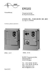
Remote display terminal option, ER23K<br />
This terminal is a local control unit which can be mounted on the door of the wall-mounted or floor-standing enclosure. It has a cable with<br />
connectors, which is connected to the drive serial link (see the manual supplied with the terminal). Its display capabilities are practically<br />
identical to those of the ER23K. With this terminal, however, up and down arrows are used for navigation rather than a jog dial. There is<br />
also an access locking switch for the <strong>menu</strong>s. There are three buttons for controlling the drive (1):<br />
• FWD/REV: Reversal of the direction of rotation<br />
• RUN: Motor run command<br />
• STOP/RESET: Motor stop command or reset<br />
Pressing the button a first time stops the motor, and if DC injection standstill braking is configured, pressing it a second time stops this<br />
braking.<br />
View of the front panel:: View of the rear panel :<br />
4-character<br />
display<br />
Note: Protection via customer confidential code has priority over the switch.<br />
Note:<br />
• The remote terminal access locking switch also locks access by the drive keys.<br />
• When the remote display terminal is disconnected, any locking remains active for the drive keys.<br />
• The remote display terminal will only be active if the [Modbus baud rate] (tbr) parameter in the [COMMUNICATION] (COM-) <strong>menu</strong>,<br />
page 92, still has its factory setting: [19.2 Kbps] (19.2).<br />
(1)To activate the buttons on the remote display terminal, you first have to configure [HMI command] (LCC) = [Yes] (YES), page 58.<br />
Saving and loading configurations<br />
Connector<br />
Access locking switch:<br />
• Position:<br />
• Position:<br />
Up to four complete configurations for ER23K drives without an option card can be stored on the remote display terminal. These<br />
configurations can be saved, transported and transferred from one drive to another of the same rating. 4 different operations for the same<br />
device can also be stored on the terminal.<br />
See the [Saving config.] (SCS) and [Restore config.] (FCS) parameters in the [MOTOR CONTROL] (drC-) <strong>menu</strong>, pages 43 and 44, the<br />
[INPUTS / OUTPUTS CFG] (I-O-) <strong>menu</strong>, pages 47 and 47, the [COMMAND] (CtL-) <strong>menu</strong>, pages 59 and 59, and the [APPLICATION<br />
FUNCT.] (FUn-) <strong>menu</strong>, pages 85 and 85.<br />
To transfer a configuration between an ER23K and an ER22, follow the procedure on page 85.<br />
[MONITORING] (SUP-) and [SPEED<br />
REFERENCE] (rEF-) <strong>menu</strong>s can be<br />
accessed.<br />
[SETTINGS] (SEt-), [MONITORING]<br />
(SUP-) and [SPEED REFERENCE]<br />
(rEF-) can be accessed.<br />
• Position: All <strong>menu</strong>s can be accessed<br />
13
Remote graphic display terminal option, ER40<br />
Description of the terminal<br />
Thanks to the screen size of this graphic display terminal, which works with FLASH V1.1IE19 or higher and is part of the ER40, it is possible<br />
to display more detailed information than can be shown on an on-board display. It is connected in the same way as the ER23K remote<br />
display terminal.<br />
Note: Keys 3, 4, 5 and 6 can be used to control the drive directly, if control via the terminal is activated.<br />
To activate the buttons on the remote display terminal, you first have to configure [HMI command] (LCC) = [Yes] (YES), page 58.<br />
14<br />
1 Graphic display<br />
2 Function keys:<br />
F1: CODE<br />
F2, F3: not used<br />
F4: MODE<br />
3 Button to stop/reset<br />
4 Run button<br />
5 Navigation button:<br />
7 ESC button:cancels a value, a<br />
parameter or a <strong>menu</strong> to return<br />
to the previous selection<br />
6 Button for reversing the direction<br />
of rotation of the motor<br />
• Press (ENT): - To save the current value<br />
- To enter the selected <strong>menu</strong> or parameter<br />
• Turn CW/CCW: - To increase or decrease a value<br />
- To go to the next or previous line<br />
- To increase or decrease the reference if control via<br />
the display terminal is activated
Remote graphic display terminal option, ER40 (continued)<br />
Powering up the graphic display terminal for the first time<br />
When powering up the graphic display terminal for the first time, the user has to select the required language.<br />
English<br />
Français<br />
Deutsch<br />
Espanol<br />
Italiano<br />
Chinese<br />
Russian<br />
Turkish<br />
3 seconds<br />
or ENT<br />
LANGUAGE<br />
ER23K<br />
1.5kW/2HP 200/240V<br />
MAIN MENU<br />
DRIVE MENU<br />
LANGUAGE<br />
DRIVE MENU<br />
SPEED REFERENCE<br />
SETTINGS<br />
MOTOR CONTROL<br />
INPUTS / OUTPUTS CFG<br />
COMMAND<br />
Code Mode<br />
APPLICATION FUNCT.<br />
FAULT MANAGEMENT<br />
COMMUNICATION<br />
Display after the graphic display terminal has been<br />
powered up for the first time.<br />
Select the language and press ENT.<br />
The drive's rating details will now appear.<br />
The [MAIN MENU]<br />
follows automatically.<br />
Automatically switches to the [DRIVE MENU]<br />
<strong>menu</strong> after 3 seconds.<br />
Select the <strong>menu</strong> and press ENT.<br />
15
Remote graphic display terminal option, ER40 (continued)<br />
Powering up the drive for the first time<br />
When powering up the drive for the first time, the user immediately accesses the 3 parameters below: [Standard mot. freq] (bFr), [Ref.1<br />
channel] (Fr1), and [2/3 wire control] (tCC), page 29. .<br />
16<br />
3 seconds<br />
ESC<br />
ER23K<br />
1.5kW/2HP 200/240V<br />
MAIN MENU<br />
DRIVE MENU<br />
LANGUAGE<br />
DRIVE MENU<br />
Standard mot. freq<br />
2/3 wire control<br />
Ref.1 channel<br />
SPEED REFERENCE<br />
SETTINGS<br />
MOTOR CONTROL<br />
INPUTS / OUTPUTS CFG<br />
COMMAND<br />
APPLICATION FUNCT.<br />
FAULT MANAGEMENT<br />
COMMUNICATION<br />
DRIVE MENU<br />
Ready<br />
Code Mode<br />
Display after the drive has been powered up for the<br />
first time.<br />
The [MAIN MENU]<br />
follows automatically.<br />
Automatically switches to the [DRIVE MENU]<br />
<strong>menu</strong> after 3 seconds.<br />
Select the <strong>menu</strong> and press ENT.<br />
The word "Ready" appears on the graphic display<br />
terminal if you press the ESC key when in the<br />
[DRIVE MENU].
Remote graphic display terminal option, ER40 (continued)<br />
Subsequent power-ups<br />
3 seconds<br />
ESC<br />
ER23K<br />
1.5kW/2HP 200/240V<br />
MAIN MENU<br />
DRIVE MENU<br />
LANGUAGE<br />
DRIVE MENU<br />
SPEED REFERENCE<br />
SETTINGS<br />
MOTOR CONTROL<br />
INPUTS / OUTPUTS CFG<br />
COMMAND<br />
Code Mode<br />
APPLICATION FUNCT.<br />
FAULT MANAGEMENT<br />
COMMUNICATION<br />
DRIVE MENU<br />
Ready<br />
Code Mode<br />
Display after powering up.<br />
The [MAIN MENU]<br />
follows automatically.<br />
Automatically switches to the [DRIVE MENU]<br />
<strong>menu</strong> after 3 seconds.<br />
Select the <strong>menu</strong> and press ENT.<br />
The word "Ready" appears on the graphic display<br />
terminal if you press the ESC key when in the<br />
[DRIVE MENU].<br />
17
Remote display terminal option, ER12<br />
Description of the terminal<br />
This terminal is a local control unit which can be mounted on the door of the wall-mounted or floor-standing enclosure. It has a cable with<br />
connectors, which is connected to the drive serial link (see the manual supplied with the terminal). Its display capabilities are practically<br />
identical to those of the ER23. With this terminal, up and down arrows are used for navigation rather than a jog dial.<br />
(1) If the drive is locked by a code ([PIN code 1] (COd), page 97), pressing the Mode key enables you to switch from the [MONITORING]<br />
(SUP-) <strong>menu</strong> to the [SPEED REFERENCE] (rEF-) <strong>menu</strong> and vice versa.<br />
To activate the buttons on the remote display terminal, you first have to configure [HMI command] (LCC) = [Yes] (YES), page 58.<br />
18<br />
1 Graphic display<br />
2 MODE button (1): If [SPEED<br />
REFERENCE] (rEF-) is displayed,<br />
this will take you to the<br />
[SETTINGS] (SEt-) <strong>menu</strong>. If not, it<br />
will take you to the [SPEED<br />
REFERENCE] (rEF-) <strong>menu</strong>.<br />
3 ESC button<br />
Used to quit a <strong>menu</strong>/parameter or<br />
remove the currently displayed<br />
value in order to revert<br />
to the previous value<br />
retained in the memory<br />
4 RUN button<br />
Executes the function<br />
assuming it has been<br />
configured<br />
5 Navigation keys<br />
6 ENT button<br />
Used to save the current value or<br />
access the selected <strong>menu</strong>/parameter<br />
7 STOP button<br />
Used to stop the motor and<br />
perform a reset<br />
8 Button for reversing the direction<br />
of rotation of the motor
Structure of the parameter tables<br />
The parameter tables contained in the descriptions of the various <strong>menu</strong>s are organized as follows.<br />
Example :<br />
1<br />
2<br />
3<br />
4<br />
APPLICATION FUNCT.] <strong>menu</strong> (Fun-)<br />
Code Name/Description Adjustment<br />
range<br />
Factory<br />
setting<br />
PI- • [PI regulator]<br />
Note: The "PI regulator" function is incompatible with several functions (see page 20). It can only<br />
be configured if these functions are unassigned, in particular the summing inputs (set [Summing<br />
ref. 2] (SA2) to [No] (nO), page 67) and the preset speeds (set [2 preset speeds] (PS2) and<br />
[4 preset speeds] (PS4) to [No] (nO), page 69) which will have been assigned as part of the<br />
factory settings.<br />
PIF • [PID feedback ass.]<br />
no<br />
AI1<br />
A12<br />
A13<br />
1. Name of <strong>menu</strong> on 4-digit 7-segment display<br />
2. Sub<strong>menu</strong> code on 4-digit 7-segment display<br />
3. Parameter code on 4-digit 7-segment display<br />
4. Parameter value on 4-digit 7-segment display<br />
- [Non] (nO): not assigned<br />
- [AI1] (AI1): analog input AI1<br />
- [AI2] (AI2): analog input AI2<br />
- [AI3] (AI3): analog input AI3<br />
7<br />
5<br />
6<br />
8<br />
[Non] (nO)<br />
5. Name of <strong>menu</strong> on ER40 graphic display terminal<br />
6. Name of sub<strong>menu</strong> on ER40 graphic display terminal<br />
7. Name of parameter on ER40 graphic display terminal<br />
8. Value of parameter on ER40 graphic display terminal<br />
19
Compatibility of functions<br />
Incompatible functions<br />
The following functions will be inaccessible or deactivated in the cases described below:<br />
Automatic restart<br />
This is only possible for the 2-wire level control type ([2/3 wire control] (tCC) = [2 wire] (2C) and [2 wire type] (tCt) = [Level] (LEL) or<br />
[Fwd priority] (PFO)).<br />
Catch on the fly<br />
This is only possible for the 2-wire level control type ([2/3 wire control] (tCC) = [2 wire] (2C) and [2 wire type] (tCt) = [Level] (LEL) or<br />
[Fwd priority] (PFO)).<br />
This function is locked if automatic standstill injection has been configured as DC ([Auto DC injection] (AdC) = [Continuous] (Ct)).<br />
Function compatibility table<br />
The choice of application functions may be limited by the number of I/O and by the fact that some functions are incompatible with one<br />
another. Functions which are not listed in this table are compatible.<br />
If there is an incompatibility between functions, the first function configured will prevent the others being configured.<br />
To configure a function, first check that functions which are incompatible with it are unassigned, especially those which are<br />
assigned in the factory settings.<br />
(1)Excluding special application with reference channel [Ref.2 channel] (Fr2) (see diagrams 51 and 53)<br />
Priority functions (functions which cannot be active at the same time):<br />
Stop functions take priority over run commands.<br />
Speed references via logic command take priority over analog references.<br />
20<br />
Summing inputs (factory setting) ���� � ���� �<br />
+/- speed (1) ���� ���� ���� ����<br />
Management of limit switches ����<br />
Preset speeds (factory setting) f ���� ���� �<br />
PI regulator ���� ���� ���� ���� ���� ����<br />
Jog operation f ���� f ���� ����<br />
Brake control ���� ���� ����<br />
Summing inputs (factory setting)<br />
DC injection stop ���� �<br />
Fast stop �<br />
Freewheel stop f f<br />
���� Incompatible functions Compatible functions Not applicable<br />
f � The function marked with the arrow takes priority over the other.<br />
+/- speed (1)<br />
Management of limit switches<br />
Preset speeds (factory setting)<br />
PI regulator<br />
Jog operation<br />
Brake control<br />
DC injection stop<br />
Fast stop<br />
Freewheel stop
Compatibility of functions<br />
Logic and analog input application functions<br />
Each of the functions on the following pages can be assigned to one of the inputs.<br />
A single input can activate several functions at the same time (reverse and 2nd ramp for example). The user must therefore ensure that<br />
these functions can be used at the same time.<br />
The [MONITORING] (SUP-) <strong>menu</strong> ([[LOGIC INPUT CONF.]] (LIA-) parameter, page 98, and [[ANALOG INPUTS IMAGE]] (AIA-) parameter,<br />
page 98) can be used to display the functions assigned to each input in order to check their compatibility.<br />
Before assigning a reference, command or function to a logic or analog input, the user must check that this input has not already been<br />
assigned in the factory settings and that no other input has been assigned to an incompatible or unwanted function.<br />
• Example of incompatible function to be unassigned:<br />
In order to use the "+speed/-speed" function, the preset speeds and summing input 2 must first be unassigned.<br />
The table below lists the factory-set input assignments and the procedure for unassigning them.<br />
Assigned input Function Code To unassign, set to: Page<br />
LI2 Run reverse rrS nO 46<br />
LI3 2 preset speeds PS2 nO 69<br />
LI4 4 preset speeds PS4 nO 69<br />
AI1 Reference 1 Fr1 Anything but AI1 56<br />
LI1 Run forward tCC 2C or 3C 45<br />
AI2 Summing input 2 SA2 nO 67<br />
21
List of functions that can be assigned to inputs/outputs<br />
22<br />
Logic inputs Page Code Factory setting<br />
Not assigned - - LI5 - LI6<br />
Run forward - - LI1<br />
2 preset speeds 69 PS2 LI3<br />
4 preset speeds 69 PS4 LI4<br />
8 preset speeds 69 PS8<br />
16 preset speeds 70 PS16<br />
2 preset PI references 77 Pr2<br />
4 preset PI references 78 Pr4<br />
+ speed 74 USP<br />
- speed 74 dSP<br />
Jog operation 72 JOG<br />
Ramp switching 62 rPS<br />
2nd current limit switching 81 LC2<br />
Fast stop via logic input 63 FSt<br />
DC injection via logic input 63 dCI<br />
Freewheel stop via logic input 64 nSt<br />
Run reverse 46 rrS LI2<br />
External fault 88 EtF<br />
RESET 87 rSF<br />
Forced local mode 93 FLO<br />
Reference switching 57 rFC<br />
Control channel switching 58 CCS<br />
Motor switching 82 CHP<br />
Forward limit switch 84 LAF<br />
Reverse limit switch 84 LAr<br />
Fault inhibition 91 InH<br />
Analog inputs Page Code Factory setting<br />
Not assigned - - AI3<br />
Reference 1 56 Fr1 AI1<br />
Reference 2 56 Fr2<br />
Summing input 2 67 SA2 AI2<br />
Summing input 3 67 SA3<br />
PI regulator feedback 77 PIF
List of functions that can be assigned to inputs/outputs<br />
Analog/logic output Page Code Factory setting<br />
Not assigned - - AOC/AOV<br />
Motor current 46 OCr<br />
Motor frequency 46 OFr<br />
Motor torque 46 Otr<br />
Power supplied by the drive 46 OPr<br />
Drive detected fault (logic data) 46 FLt<br />
Drive running (logic data) 46 rUn<br />
Frequency threshold reached (logic data) 46 FtA<br />
High speed (HSP) reached (logic data) 46 FLA<br />
Current threshold reached (logic data) 46 CtA<br />
Frequency reference reached (logic data) 46 SrA<br />
Motor thermal threshold reached (logic data) 46 tSA<br />
Brake sequence (logic data) 46 bLC<br />
Relay Page Code Factory setting<br />
Not assigned - - R2<br />
Detected fault 47 FLt R1<br />
Drive running 47 rUn<br />
Frequency threshold reached 47 FtA<br />
High speed (HSP) reached 47 FLA<br />
Current threshold reached 47 CtA<br />
Frequency reference reached 47 SrA<br />
Motor thermal threshold reached 47 tSA<br />
Brake sequence 47 bLC<br />
Copy of the logic input 47 LI1 to LI6<br />
23
List of functions that can be assigned to the Network and<br />
Modbus control word bits<br />
24<br />
Bits 11 to 15 of the control word Page Code<br />
2 preset speeds 69 PS2<br />
4 preset speeds 69 PS4<br />
8 preset speeds 69 PS8<br />
16 preset speeds 70 PS16<br />
2 preset PI references 77 Pr2<br />
4 preset PI references 78 Pr4<br />
Ramp switching 62 rPS<br />
2nd current limit switching 81 LC2<br />
Fast stop via logic input 63 FSt<br />
DC injection 63 dCI<br />
External fault 88 EtF<br />
Reference switching 57 rFC<br />
Control channel switching 58 CCS<br />
Motor switching 82 CHP
Checklist<br />
Carefully read the information contained in the programming, installation and simplified manuals, as well as the information in the catalog.<br />
Before starting to use the drive, please check the following points relating to mechanical and electrical installations.<br />
For the full range of documentation, please visit www.blemo.com.<br />
1. Mechanical installation (see the simplified and installation manuals)<br />
• For details of the different installation types and recommendations concerning ambient temperature, please refer to the installation<br />
instructions in the simplified or installation manuals.<br />
• Install the drive vertically in accordance with the specifications. Please refer to the installation instructions in the simplified or<br />
installation manuals.<br />
• When using the drive, both the environmental conditions defined under standard 60721-3-3 and the levels defined in the catalog must<br />
be respected.<br />
• Install the required options for your application. Refer to the catalog for details.<br />
2. Electrical installation (see the simplified and installation manuals)<br />
• Ground the drive. See the sections on how to ground equipment in the simplified and installation manuals.<br />
• Make sure the input supply voltage matches the nominal drive voltage and connect the line supply in accordance with the simplified<br />
and installation manuals.<br />
• Make sure you use appropriate input line fuses and circuit breakers. See the simplified and installation manuals.<br />
• Arrange the cables for the control terminals as required (see the simplified and installation manuals). Separate the supply and control<br />
cables in accordance with EMC compatibility rules.<br />
• The ER23-...K and ER23-.../4K ranges include an EMC filter Using an IT jumper helps reduce leakage current. This is explained in<br />
the paragraph about the internal EMC filter on the ER23-...K and the ER23-.../4K in the installation manual.<br />
• Make sure the motor connections are right for the voltage (star, delta).<br />
3. Using and starting up the drive<br />
• Start the drive. [Standard mot. freq] (bFr), page 28, is displayed the first time the drive is powered up. Make sure the frequency defined<br />
by frequency bFr (the factory setting is 50 Hz) matches the motor's frequency.<br />
• When the drive is powered up for the first time, the [Ref.1 channel] (Fr1) parameter, page 28, and the [2/3 wire control] (tCC)<br />
parameter, page 29, are displayed after [Standard mot. freq] (bFr). These parameters will need to be adjusted if you wish to control<br />
the drive locally.<br />
• When the drive is powered up subsequently, [Ready] (rdY) is displayed on the HMI.<br />
• The [Restore config.] (FCS) function, page 44, is used to reinitialize the drive with the factory settings.<br />
25
Programming<br />
Description of the HMI<br />
Functions of the display and the keys<br />
Normal display, with no fault code displayed and no startup:<br />
26<br />
• REF LED, illuminated if<br />
[SPEED REFERENCE]<br />
(rEF-) <strong>menu</strong> is active<br />
• Load LED<br />
• MON LED, illuminated if<br />
[MONITORING] (SUP-)<br />
<strong>menu</strong> is active<br />
• CONF LED, illuminated if the<br />
[SETTINGS] (SEt-),<br />
[MOTOR CONTROL]<br />
(drC-),[INPUTS / OUTPUTS<br />
CFG] (I-O-), [COMMAND]<br />
(CtL-), [APPLICATION<br />
FUNCT] (FUn-), [FAULT<br />
MANAGEMENT] (FLt-)<br />
or [COMMUNICATION]<br />
(COM-) <strong>menu</strong>s are active<br />
• MODE button (1): If<br />
[SPEED REFERENCE]<br />
(rEF-) is displayed, this will<br />
take you to the<br />
[SETTINGS] (SEt-) <strong>menu</strong>.<br />
If not, it will take you to the<br />
[SPEED REFERENCE]<br />
(rEF-) <strong>menu</strong>.<br />
• RUN button: Controls powering up<br />
of the motor for forward running if<br />
the [2/3 wire control] (tCC)<br />
parameter in the [INPUTS /<br />
OUTPUTS CFG] (I-O-) <strong>menu</strong> is set<br />
to [Local] (LOC), page 45<br />
• 4 x 7 segment display<br />
• 2 CANopen status LEDs<br />
• Used to quit a <strong>menu</strong> or parameter<br />
or to clear the value displayed in<br />
order to revert to the value in the<br />
memory<br />
• Jog dial - can be used for<br />
navigation by turning it clockwise<br />
or counter-clockwise - pressing<br />
the jog dial enables the user to<br />
make a selection or confirm<br />
information.<br />
Functions as a potentiometer if [Ref.1<br />
channel] (Fr1-) in the [COMMAND]<br />
(CtL-) <strong>menu</strong> is set to [Image input<br />
AIV1] (AIV1)<br />
STOP/RESET button<br />
• Enables detected fault to be reset<br />
• Can be used to control motor stopping<br />
- If [2/3 wire control] (tCC) is not set to<br />
[Local] (LOC), freewheel stop<br />
- If [2/3 wire control] (tCC) is set to [Local]<br />
(LOC), stop on ramp or freewheel stop<br />
during DC injection braking<br />
- : Displays the parameter selected in the [MONITORING] (SUP-) <strong>menu</strong> (default: motor frequency).<br />
If the current is limited, the display flashes. In such cases, CLI will appear at the top left if an ER40 graphic display terminal is<br />
connected to the drive.<br />
- InIt: Initialization sequence<br />
- rdY: Drive ready<br />
- dCb: DC injection braking in progress<br />
- nSt: Freewheel stop<br />
- FSt: Fast stop<br />
- tUn : Auto-tuning in progress<br />
In the event of a detected fault, the display will flash to notify the user accordingly. If an ER40 graphic display terminal is<br />
connected, the name of the detected fault will be displayed.<br />
(1) If the drive is locked by a code ([PIN code 1] (COd), page 97), pressing the Mode key enables you to switch from the [MONITORING]<br />
(SUP-) <strong>menu</strong> to the [SPEED REFERENCE] (rEF-) <strong>menu</strong> and vice versa.
Programming<br />
Structure of the <strong>menu</strong>s<br />
Powering up Parameter selection<br />
These three parameters are<br />
only visible when the drive is<br />
powered up for the first time.<br />
The settings can be amended<br />
subsequently in the <strong>menu</strong>s:<br />
[MOTOR CONTROL] (drC-)<br />
for [Standard mot. freq] (bFr),<br />
[COMMAND] (CtL-) for [Ref.1<br />
channel] (Fr1)<br />
[INPUTS / OUTPUTS CFG]<br />
(I-O-) for [2/3 wire control]<br />
(tCC)<br />
[SPEED REFERENCE] (rEF-)<br />
[SETTINGS] (SEt-)<br />
[MOTOR CONTROL] (drC-)<br />
[INPUTS / OUTPUTS CFG]<br />
(I-O-)<br />
[COMMAND] (CtL-)<br />
[APPLICATION FUNCT.] (FUn-)<br />
[FAULT MANAGEMENT] (FLt)<br />
[COMMUNICATION] (COM-)<br />
[MONITORING] (SUP-)<br />
On the 7-segment display, a dash after <strong>menu</strong> and sub<strong>menu</strong> codes is used to differentiate them from parameter codes.<br />
Examples: [APPLICATION FUNCT.] (FUn-) <strong>menu</strong>, [Acceleration] (ACC) parameter<br />
27
Programming<br />
Configuring the [Standard mot. freq] (bFr), [2/3 wire control] (tCC), and<br />
[Ref.1 channel] (Fr1) parameters<br />
These parameters can only be modified when the drive is stopped and no run command is present.<br />
28<br />
Code Description Adjustment<br />
range<br />
Factory<br />
setting<br />
bFr • [Standard mot. freq] [50Hz IEC] (50)<br />
50<br />
60<br />
Fr1 • [Ref.1 channel]<br />
AI1<br />
AI2<br />
AI3<br />
AIU1<br />
UPdt<br />
UPdH<br />
LCC<br />
Mdb<br />
nEt<br />
This parameter is only visible the first time the drive is powered up.<br />
It can be modified at any time in the [MOTOR CONTROL] (drC-) <strong>menu</strong>.<br />
[50Hz IEC] (50): 50 Hz<br />
[60Hz NEMA] (60): 60 Hz<br />
This parameter modifies the presets of the following parameters: [High speed] (HSP), page 32, [Freq.<br />
threshold] (Ftd), page 37, [Rated motor freq.] (FrS), page 39, and [Max frequency] (tFr), page 42<br />
- [AI1] (AI1) - Analog input AI1<br />
- [AI2] (AI2) - Analog input AI2<br />
- [AI3] (AI3) - Analog input AI3<br />
- [Network AI] (AIV1) - In terminal control mode, the jog dial functions as a potentiometer.<br />
[AI1] (AI1)<br />
If [ACCESS LEVEL] (LAC) = [Level 2] (L2) or [Level 3] (L3), the following additional assignments are possible:<br />
- [+/- SPEED] (UPdt): +/- speed reference via LI. See configuration page 74.<br />
- [+/-spd HMI] (UPdH): +/- speed reference by turning the jog dial on the ER23K keypad.<br />
To use, display the frequency [Output frequency] (rFr), page 95. The +/- speed function via the keypad or the<br />
terminal is controlled from the [MONITORING] (SUP-) <strong>menu</strong> by selecting the [Output frequency] (rFr)<br />
parameter.<br />
If [ACCESS LEVEL] (LAC) = [Level 3] (L3), the following additional assignments are possible:<br />
- [HMI] (LCC) reference via the remote display terminal, [HMI Frequency ref.] (LFr) parameter in the<br />
[SETTINGS] (SEt-) <strong>menu</strong>, page 31<br />
- [Modbus] (Mdb): Reference via Modbus<br />
- [Network] (nEt): Reference via network communication protocol
Programming<br />
Code Description Adjustment<br />
range<br />
2 s<br />
tCC • [2/3 wire control]<br />
2 s<br />
2C<br />
3C<br />
LOC<br />
UNINTENDED EQUIPMENT OPERATION<br />
DANGER<br />
Factory<br />
setting<br />
[2 wire] (2C)<br />
When the [2/3 wire control] (tCC) parameter is changed, the [Reverse assign.] (rrS) parameter, page 46, and the<br />
[2 wire type] (tCt) parameter, page 45, and all the assignments involving the logic inputs will revert to their default<br />
values.<br />
Check that this change is compatible with the wiring diagram used.<br />
Failure to follow these instructions will result in death or serious injury.<br />
Control configuration:<br />
- [2 wire] (2C): 2-wire control<br />
- [3 wire] (3C): 3-wire control<br />
- [Local] (LOC): Local control (RUN/STOP/RESET drive) (invisible if [ACCESS LEVEL] (LAC) = [Level 3] (L3),<br />
page 56)<br />
2-wire control: The open or closed state of the input controls running or stopping.<br />
Wiring example:<br />
LI1: Forward<br />
LIx: Reverse<br />
3-wire control (pulse control): A "forward" or "reverse" pulse is sufficient to control startup, a "stop" pulse is<br />
sufficient to control stopping.<br />
Wiring example:<br />
LI1: Stop<br />
LI2: Forward<br />
LIx: Reverse<br />
The jog dial (ENT) needs to be pressed and held down (for 2 s) to change the assignment for this parameter.<br />
29
EF-<br />
SEt-<br />
drC-<br />
I-0-<br />
CtL-<br />
FUn-<br />
FLt-<br />
COM-<br />
SUP-<br />
[SPEED REFERENCE] (rEF-) <strong>menu</strong><br />
The [SPEED REFERENCE] (rEF-) <strong>menu</strong> displays [HMI Frequency ref.] (LFr), [Image input AIU1] (AIU1) or [Frequency ref.] (FrH) depending<br />
on which control channel is active.<br />
During local control, the HMI's jog dial functions as a potentiometer, making it possible to increase or reduce the reference value within<br />
limits defined by the [Low speed] (LSP) and [High speed] (HSP) parameters.<br />
When local control is deactivated, by the [Ref.1 channel] (Fr1) parameter, only the reference values are displayed. The value will be readonly<br />
and can only be changed via the jog dial (the speed reference is supplied by an AI or another source).<br />
The reference displayed will depend on how the drive has been configured.<br />
30<br />
Code Description Factory setting<br />
LFr • [HMI Frequency ref.] 0 to 500 Hz<br />
This parameter only appears if the function has been enabled.<br />
It is used to change the speed reference from the remote control.<br />
ENT does not have to be pressed to enable a change of reference.<br />
AIU1 • [Image input AIU1] 0 to 100%<br />
Used to amend the speed reference via the jog dial<br />
FrH • [Frequency ref.] LSP to HSP Hz<br />
This parameter is read-only. It enables you to display the speed reference applied to the motor, regardless of<br />
which reference channel has been selected.
[SETTINGS] (SEt-) <strong>menu</strong><br />
The adjustment parameters can be modified with the drive running or stopped.<br />
Note: Changes should preferably be made with the drive stopped.<br />
Code Description Adjustment range Factory setting<br />
LFr • [HMI Frequency ref.] 0 to HSP -<br />
*<br />
rPI<br />
*<br />
This parameter is displayed if [HMI command] (LCC) = [Yes] (YES), page 58 or if [Ref.1 channel] (Fr1)/[Ref.2<br />
channel] (Fr2) = [HMI] (LCC) page 56, and if a remote display terminal is connected. In such cases, [HMI<br />
Frequency ref.] (LFr) can also be accessed via the drive's keypad.<br />
[HMI Frequency ref.] (LFr) is reinitialized to 0 when power is switched off.<br />
• [Internal PID ref.] 0.0 to 100% 0%<br />
Parameter is only visible if [PID feedback ass.] (PIF) is not set to [No] (nO), page 77.<br />
ACC • [Acceleration] In accordance with<br />
Inr, page 61<br />
Defined to accelerate from 0 to the nominal frequency [Rated motor freq.] (FrS) in the [MOTOR CONTROL]<br />
(drC-) <strong>menu</strong>.<br />
AC2 • [Acceleration 2] In accordance with<br />
Inr, page 61<br />
*<br />
Parameter can be accessed if [Ramp 2 threshold] (Frt) > 0, page 62, or if [Ramp switch ass.] (rPS) is assigned,<br />
page 62.<br />
dE2 • [Deceleration 2] In accordance with<br />
Inr, page 61<br />
*<br />
Parameter can be accessed if [Ramp 2 threshold] (Frt) > 0, page 62, or if [Ramp switch ass.] (rPS) is assigned,<br />
page 62.<br />
dEC • [Deceleration] In accordance with<br />
Inr, page 61<br />
*<br />
Speed reference via the display terminal<br />
Scaling factor for the [Cust. output value] (SPd1) parameter<br />
Defined to decelerate from the nominal frequency [Rated motor freq.] (FrS) (parameter in the [MOTOR CONTROL]<br />
(drC-)) <strong>menu</strong> to 0.<br />
Check that the value for [Deceleration] (dEC) is not too low in relation to the load to be stopped.<br />
These parameters only appear if the corresponding function has been selected in another <strong>menu</strong>. When the parameters can<br />
also be accessed and set from within the configuration <strong>menu</strong> for the corresponding function, their description is detailed in<br />
these <strong>menu</strong>s, on the pages indicated, to aid programming.<br />
3 s<br />
5 s<br />
5 s<br />
3 s<br />
31<br />
rEF-<br />
SEt-<br />
drC-<br />
I-0-<br />
CtL-<br />
FUn-<br />
FLt-<br />
COM-<br />
SUP-
EF-<br />
SEt-<br />
drC-<br />
I-0-<br />
CtL-<br />
FUn-<br />
FLt-<br />
COM-<br />
SUP-<br />
[SETTINGS] (SEt-) <strong>menu</strong><br />
(1)In corresponds to the nominal drive current indicated in the Installation Manual and on the drive nameplate.<br />
32<br />
Code Description Adjustment<br />
range<br />
tA1 • [Begin Acc round] 0 to 100 10<br />
*<br />
Parameter can be accessed if the [Ramp type] (rPt) = [Customized] (CUS), page 60.<br />
tA2 • [End Acc round] 0 to (100-tA1) 10<br />
*<br />
Parameter can be accessed if the [Ramp type] (rPt) = [Customized] (CUS), page 60.<br />
tA3 • [Begin Dec round] 0 to 100 10<br />
*<br />
Parameter can be accessed if the [Ramp type] (rPt) = [Customized] (CUS), page 60.<br />
tA4 • [End Dec round] 0 to (100-tA3) 10<br />
*<br />
Parameter can be accessed if the [Ramp type] (rPt) = [Customized] (CUS), page 60.<br />
LSP • [Low speed] 0 to HSP 0<br />
Motor frequency at min. reference<br />
HSP • [High speed] LSP to tFr bFr<br />
Factory<br />
setting<br />
Motor frequency at max. reference: Ensure that this setting is appropriate for the motor and the application.<br />
ItH • [Mot. therm. current] 0.2 to 1.5 In (1) In accordance<br />
with the drive<br />
rating<br />
Set [Mot. therm. current] (ItH) to the nominal current indicated on the motor's rating plate.<br />
If you wish to suppress thermal protection, see [Overload fault mgt] (OLL), page 89.<br />
UFr • [IR compensation] 0 to 100% 20%<br />
FLG<br />
*<br />
*<br />
- For [U/F mot 1 selected] (UFt) = [SVC] (n) or [Energy sav.] (nLd), page 42: IR compensation<br />
- For [U/F mot 1 selected] (UFt) = [Cst. torque] (L) or [Var. torque] (P), page 42: Voltage boost<br />
Used to optimize the torque at very low speed (increase [IR compensation] (UFr) if the torque is insufficient).<br />
Check that the value for [IR compensation] (UFr) is not too high when the motor is in a hot state otherwise some<br />
instabilities can occur.<br />
Note: Changing [U/F mot 1 selected] (UFt), page 42, will cause [IR compensation] (UFr) to return to its factory<br />
setting (20%).<br />
• [FreqLoopGain] 1 to 100% 20%<br />
Parameter can only be accessed if [U/F mot 1 selected] (UFt) = [SVC] (n) or [Energy sav.] (nLd), page 42.<br />
The FLG parameter adjusts the drive's ability to follow the speed ramp on the basis of the inertia of the machine<br />
being driven.<br />
Too high a gain may result in operating instability.<br />
FLG low FLG correct<br />
FLG high<br />
In this case,<br />
reduce FLG.<br />
These parameters only appear if the corresponding function has been selected in another <strong>menu</strong>. When the parameters can<br />
also be accessed and set from within the configuration <strong>menu</strong> for the corresponding function, their description is detailed in<br />
these <strong>menu</strong>s, on the pages indicated, to aid programming.
[SETTINGS] (SEt-) <strong>menu</strong><br />
Code Description Adjustment range Factory setting<br />
StA • [Fr.Loop.Stab] 1 to 100% 20%<br />
*<br />
Parameter can only be accessed if [U/F mot 1 selected] (UFt) = [SVC] (n) or [Energy sav.] (nLd), page 42.<br />
Used to adapt the return to steady state after a speed transient (acceleration or deceleration), according to the<br />
dynamics of the machine.<br />
Gradually increase the stability to avoid any overspeed.<br />
In this case,<br />
SLP • [Slip compensation] 0 to 150% 100%<br />
*<br />
Parameter can only be accessed if [U/F mot 1 selected] (UFt) = [SVC] (n) or [Energy sav.] (nLd), page 42.<br />
Adjusts the slip compensation around the value set by the nominal motor speed.<br />
The speeds given on motor rating plates are not necessarily exact.<br />
• If slip setting < actual slip: the motor is not rotating at the correct speed in steady state.<br />
• If slip setting > actual slip: the motor is overcompensated and the speed is unstable.<br />
IdC • [DC inject. level 1] (2) 0 to In (1) 0.7 In (1)<br />
*<br />
Parameter can be accessed if [Type of stop] (Stt) = [DC injection] (dCI), page 63, or if [DC injection assign.] (dCI)<br />
is not set to [No] (nO), page 63.<br />
After 5 seconds, the injection current is limited to 0.5 [Mot. therm. current] (ItH) if set to a higher value.<br />
tdC • [DC injection time 2] (2) 0.1 to 30 s 0.5 s<br />
*<br />
Parameter can be accessed if [Type of stop] (Stt) = [DC injection] (dCI) , page 63.<br />
tdC1 • [Auto DC inj. time 1] 0.1 to 30 s 0.5 s<br />
*<br />
Parameter can be accessed if [Auto DC injection] (AdC) is not set to [No] (nO), page 65.<br />
SdC1 • [Auto DC inj. level 1] 0 to 1.2 In (1) 0.7 In (1)<br />
*<br />
Parameter can be accessed if [Auto DC injection] (AdC) is not set to [No] (nO), page 65.<br />
Note: Check that the motor will withstand this current without overheating.<br />
tdC2 • [Auto DC inj. time 2] 0 to 30 s 0 s<br />
*<br />
Parameter can be accessed if [Auto DC injection] (AdC) is not set to [No] (nO), page 65.<br />
SdC2 • [Auto DC inj. level 2] 0 to 1.2 In (1) 0.5 In (1)<br />
*<br />
Parameter can be accessed if [Auto DC injection] (AdC) is not set to [No] (nO), page 65.<br />
Note: Check that the motor will withstand this current without overheating.<br />
(1)In corresponds to the nominal drive current indicated in the Installation Manual and on the drive nameplate.<br />
(2)Note: These settings are not related to the "automatic standstill DC injection" function.<br />
*<br />
StA low StA correct<br />
StA high<br />
In this case,<br />
reduce StA.<br />
These parameters only appear if the corresponding function has been selected in another <strong>menu</strong>. When the parameters can<br />
also be accessed and set from within the configuration <strong>menu</strong> for the corresponding function, their description is detailed in<br />
these <strong>menu</strong>s, on the pages indicated, to aid programming.<br />
33<br />
rEF-<br />
SEt-<br />
drC-<br />
I-0-<br />
CtL-<br />
FUn-<br />
FLt-<br />
COM-<br />
SUP-
EF-<br />
SEt-<br />
drC-<br />
I-0-<br />
CtL-<br />
FUn-<br />
FLt-<br />
COM-<br />
SUP-<br />
[SETTINGS] (SEt-) <strong>menu</strong><br />
34<br />
Code Description Adjustment range Factory setting<br />
JPF • [Skip Frequency] 0 to 500 Hz 0 Hz<br />
Helps to prevent prolonged operation at a frequency range of ± 1 Hz around [Skip Frequency] (JPF). This function<br />
helps to prevent a critical speed which leads to resonance. Setting the function to 0 renders it inactive.<br />
JF2 • [Skip Frequency 2] 1 to 500 Hz 0 Hz<br />
Helps to prevent prolonged operation at a frequency range of ± 1 Hz around [Skip Frequency 2] (JF2). This<br />
function helps to prevent a critical speed which leads to resonance. Setting the function to 0 renders it inactive.<br />
JGF • [Jog frequency] 0 to 10 Hz 10 Hz<br />
*<br />
Parameter can be accessed if [JOG] (JOG) is not set to [No] (nO), page 72.<br />
rPG • [PID prop. gain] 0.01 to 100 1<br />
*<br />
Parameter is only visible if [PID feedback ass.] (PIF) is not set to [No] (nO), page 77.<br />
It provides dynamic performance when PI feedback is changing quickly.<br />
rIG • [PID integral gain] 0.01 to 100/s 1<br />
*<br />
Parameter is only visible if [PID feedback ass.] (PIF) is not set to [No] (nO), page 77.<br />
It provides static precision when PI feedback is changing slowly.<br />
FbS • [PID fbk scale factor] 0.1 to 100 1<br />
*<br />
Parameter is only visible if [PID feedback ass.] (PIF) is not set to [No] (nO), page 77.<br />
For adapting the process.<br />
PIC • [PID correct. reverse] [No] (nO)<br />
nO<br />
YES<br />
*<br />
Parameter is only visible if [PID feedback ass.] (PIF) is not set to [No] (nO), page 77.<br />
- [No] (nO): Normal<br />
- [Yes] (YES): Reverse<br />
rP2 • [Preset ref. PID 2] 0 to 100% 30%<br />
*<br />
Parameter is only visible if [PID feedback ass.] (PIF) is not set to [No] (nO), page 77, and if [2 preset PID ref.]<br />
(Pr2), page 77, has been enabled by the input selection.<br />
rP3 • [Preset ref. PID 3] 0 to 100% 60%<br />
*<br />
Parameter is only visible if [PID feedback ass.] (PIF) is not set to [No] (nO), page 77, and if [4 preset PID ref.]<br />
(Pr4), page 78, has been enabled by the input selection.<br />
rP4 • [Preset ref. PID 4] 0 to 100% 90%<br />
*<br />
Parameter is only visible if [PID feedback ass.] (PIF) is not set to [No] (nO), page 77, and if [4 preset PID ref.]<br />
(Pr4), page 78, has been enabled by the input selection.<br />
SP2 • [Preset speed 2] 0 to 500 Hz 10 Hz<br />
*<br />
*<br />
See page 70.<br />
These parameters only appear if the corresponding function has been selected in another <strong>menu</strong>. When the parameters can<br />
also be accessed and set from within the configuration <strong>menu</strong> for the corresponding function, their description is detailed in<br />
these <strong>menu</strong>s, on the pages indicated, to aid programming.
[SETTINGS] (SEt-) <strong>menu</strong><br />
Code Description Adjustment<br />
range<br />
SP3 • [Preset speed 3] 0 to 500 Hz 15 Hz<br />
*<br />
See page 70.<br />
SP4 • [Preset speed 4] 0 to 500 Hz 20 Hz<br />
*<br />
See page 70.<br />
SP5 • [Preset speed 5] 0 to 500 Hz 25 Hz<br />
*<br />
See page 70.<br />
SP6 • [Preset speed 6] 0 to 500 Hz 30 Hz<br />
*<br />
See page 70.<br />
SP7 • [Preset speed 7] 0 to 500 Hz 35 Hz<br />
*<br />
See page 70.<br />
SP8 • [Preset speed 8] 0 to 500 Hz 40 Hz<br />
*<br />
See page 70.<br />
SP9 • [Preset speed 9] 0 to 500 Hz 45 Hz<br />
*<br />
See page 70.<br />
SP10 • [Preset speed 10] 0 to 500 Hz 50 Hz<br />
*<br />
See page 70.<br />
SP11 • [Preset speed 11] 0 to 500 Hz 55 Hz<br />
*<br />
See page 71.<br />
SP12 • [Preset speed 12] 0 to 500 Hz 60 Hz<br />
*<br />
See page 71.<br />
SP13 • [Preset speed 13] 0 to 500 Hz 70 Hz<br />
*<br />
See page 71.<br />
SP14 • [Preset speed 14] 0 to 500 Hz 80 Hz<br />
*<br />
See page 71.<br />
SP15 • [Preset speed 15] 0 to 500 Hz 90 Hz<br />
*<br />
See page 71.<br />
SP16 • [Preset speed 16] 0 to 500 Hz 100 Hz<br />
*<br />
*<br />
See page 71.<br />
Factory setting<br />
These parameters only appear if the corresponding function has been selected in another <strong>menu</strong>. When the parameters can<br />
also be accessed and set from within the configuration <strong>menu</strong> for the corresponding function, their description is detailed in<br />
these <strong>menu</strong>s, on the pages indicated, to aid programming.<br />
35<br />
rEF-<br />
SEt-<br />
drC-<br />
I-0-<br />
CtL-<br />
FUn-<br />
FLt-<br />
COM-<br />
SUP-
EF-<br />
SEt-<br />
drC-<br />
I-0-<br />
CtL-<br />
FUn-<br />
FLt-<br />
COM-<br />
SUP-<br />
[SETTINGS] (SEt-) <strong>menu</strong><br />
(1) In corresponds to the nominal drive current indicated in the Installation Manual and on the drive nameplate.<br />
36<br />
Code Description Adjustment<br />
range<br />
Factory setting<br />
CLI • [Current Limitation] 0.25 to 1.5 In (1) 1.5 In (1)<br />
Used to limit the torque and the temperature rise of the motor.<br />
CL2 • [I Limit. 2 value] 0.25 to 1.5 In (1) 1.5 In (1)<br />
*<br />
Parameter is only visible if [Current limit 2] (LC2) is not set to [No] (nO), page 81.<br />
tLS • [Low speed time out] 0 to 999.9 s 0 (no time limit)<br />
After operating at [Low speed] (LSP) for a given time, the motor is stopped automatically. The motor restarts if<br />
the frequency reference is greater than the [Low speed] (LSP) and if a run command is still present.<br />
Note: Value 0 corresponds to an unlimited period.<br />
rSL • [PID wake up thresh.] 0 to 100% 0%<br />
*<br />
Parameter is only visible if [PID feedback ass.] (PIF) is not set to [No] (nO), page 77.<br />
If the "PI" and "Low speed operating time" [Low speed time out] (tLS) functions, page 36, are configured at the<br />
same time, the PI regulator may attempt to set a speed lower than [Low speed] (LSP).<br />
This results in unsatisfactory operation, which consists of starting, operating at [Low speed] (LSP), then<br />
stopping, and so on.<br />
The [PID wake up thresh.] (rSL) parameter (restart error threshold) is used to set a minimum PID error threshold<br />
for restarting after a stop at prolonged [Low speed] (LSP).<br />
The function is inactive if [Low speed time out] (tLS) = 0.<br />
UFr2 • [IR compensation 2] 0 to 100% 20%<br />
*<br />
*<br />
For [U/F mot.2 selected] (UFt2) = [SVC] (n) or [Energy sav.] (nLd): IR compensation.<br />
For [U/F mot.2 selected] (UFt2) = [Cst. torque] (L) or [Var. torque] (P): voltage boost.<br />
Used to optimize the torque at very low speed (increase [IR compensation 2] (UFr2) if the torque is insufficient).<br />
Check that the value for [IR compensation 2] (UFr2) is not too high when the motor is in a hot state otherwise<br />
some instabilities can occur. Changing [U/F mot.2 selected] (UFt2) will cause [IR compensation 2] (UFr2) to<br />
return to its factory setting (20%).<br />
These parameters only appear if the corresponding function has been selected in another <strong>menu</strong>. When the parameters can<br />
also be accessed and set from within the configuration <strong>menu</strong> for the corresponding function, their description is detailed in<br />
these <strong>menu</strong>s, on the pages indicated, to aid programming.
[SETTINGS] (SEt-) <strong>menu</strong><br />
Code Description Adjustment<br />
range<br />
FLG2 • [FreqLoopGain 2] 0 to 100% 20%<br />
*<br />
(1)In corresponds to the nominal drive current indicated in the Installation Manual and on the drive nameplate.<br />
Factory setting<br />
Parameter can only be accessed if [U/F mot.2 selected] (UFT2) = [SVC] (n) or [Energy sav.] (nLd), page 83.<br />
The [FreqLoopGain 2] (FLG2) parameter adjusts the drive's ability to follow the speed ramp on the basis of the<br />
inertia of the machine being driven.<br />
Too high a gain may result in operating instability.<br />
StA2 • [Freq. loop stability 2] 0 to 100% 20%<br />
*<br />
Parameter can only be accessed if [U/F mot.2 selected] (UFT2) = [SVC] (n) or [Energy sav.] (nLd) , page 83.<br />
Used to adapt the return to steady state after a speed transient (acceleration or deceleration), according to the dynamics<br />
of the machine.<br />
Gradually increase the stability to avoid any overspeed.<br />
SLP2 • [Slip compensation 2] 0 to 150% 100%<br />
*<br />
Parameter can only be accessed if [U/F mot.2 selected] (UFT2) = [SVC] (n) or [Energy sav.] (nLd), page 83.<br />
Adjusts the slip compensation around the value set by the nominal motor speed.<br />
The speeds given on motor rating plates are not necessarily exact.<br />
• If slip setting < actual slip: The motor is not rotating at the correct speed in steady state.<br />
• If slip setting > actual slip: The motor is overcompensated and the speed is unstable.<br />
Ftd • [Freq. threshold] 0 to 500 Hz bFr<br />
Threshold beyond which the contact on the relay ([R1 Assignment] (r1) or [R2 Assignment] (r2) = [Freq.Th.att.]<br />
(FtA)) closes or output AOV = 10 V ([Analog./logic output] (dO) = [Freq. limit] (FtA)).<br />
ttd • [Motor therm. level] 1 to 118% 100%<br />
Threshold beyond which the contact on the relay ([R1 Assignment] (r1) or [R2 Assignment] (r2) = [Th.mot. att.]<br />
(tSA)) closes or output AOV = 10 V ([Analog./logic output] (dO) = [Drv thermal] (tSA)).<br />
Ctd • [Current threshold] 0 to 1.5 In (1) In (1)<br />
*<br />
FLG2 low FLG2 correct<br />
FLG2 high<br />
In this case,<br />
reduce FLG2.<br />
StA2 low StA2 correct<br />
In this case,<br />
reduce StA2<br />
StA2 high<br />
Threshold beyond which the contact on the relay ([R1 Assignment] (r1) or [R2 Assignment] (r2) = [I attained] (CtA))<br />
closes or output AOV = 10 V ([Analog./logic output] (dO) = [Current limit] (CtA)).<br />
These parameters only appear if the corresponding function has been selected in another <strong>menu</strong>. When the parameters can<br />
also be accessed and set from within the configuration <strong>menu</strong> for the corresponding function, their description is detailed in<br />
these <strong>menu</strong>s, on the pages indicated, to aid programming.<br />
37<br />
rEF-<br />
SEt-<br />
drC-<br />
I-0-<br />
CtL-<br />
FUn-<br />
FLt-<br />
COM-<br />
SUP-
EF-<br />
SEt-<br />
drC-<br />
I-0-<br />
CtL-<br />
FUn-<br />
FLt-<br />
COM-<br />
SUP-<br />
[SETTINGS] (SEt-) <strong>menu</strong><br />
(1)Parameter can also be accessed in the [MOTOR CONTROL] (drC-) <strong>menu</strong>.<br />
38<br />
Code Description Adjustment<br />
range<br />
SdS • [Scale factor display] 0.1 to 200 30<br />
Factory setting<br />
Used to display a value in proportion to the output frequency [Output frequency] (rFr): the machine speed, the motor<br />
speed, etc.<br />
• If [Scale factor display] (SdS) y 1, [Cust. output value] (SPd1) is displayed (possible definition = 0.01)<br />
• If 1 < [Scale factor display] (SdS) y 10, [Cust. output value] (SPd2) is displayed (possible definition = 0.1)<br />
• If [Scale factor display] (SdS) > 10, [Cust. output value] (SPd3) is displayed (possible definition = 1)<br />
• If [Scale factor display] (SdS) > 10 and [Scale factor display] (SdS) x [Output frequency] (rFr) > 9,999:<br />
the display will show<br />
[Scale factor display] (SdS) x [Output frequency] (rFr)<br />
[Cust. output value] (SPd3) = to 2 decimal places<br />
1000<br />
example: for 24,223, display will show 24.22<br />
- If [Scale factor display] (SdS) > 10 and [Scale factor display] (SdS) x [Output frequency] (rFr) > 65,535, display<br />
locked at 65.54<br />
SFr • [Switching freq.]<br />
Example: Display motor speed for<br />
4-pole motor, 1,500 rpm at 50 Hz (synchronous speed):<br />
[Scale factor display] (SdS) = 30<br />
[Cust. output value] (SPd3) = 1,500 at [Output frequency] (rFr) = 50 Hz<br />
(1) 2.0 to 16 kHz 4 kHz<br />
Parameter can also be accessed in the [MOTOR CONTROL] (drC-) <strong>menu</strong>. The frequency can be adjusted to<br />
reduce the noise generated by the motor.<br />
If the frequency has been set to a value higher than 4 kHz, in the event of excessive temperature rise, the drive<br />
will automatically reduce the switching frequency and increase it again once the temperature has returned to<br />
normal.
[MOTOR CONTROL] (drC-) <strong>menu</strong><br />
With the exception of [Auto tuning] (tUn), which can power up the motor, parameters can only be changed in stop mode, with no run<br />
command present.<br />
On the optional ER23K remote display terminal, this <strong>menu</strong> can be accessed with the switch in the position.<br />
Drive performance can be optimized by:<br />
- Entering the values given on the motor rating plate in the Drive <strong>menu</strong><br />
- Performing an auto-tune operation (on a standard asynchronous motor)<br />
Code Description Adjustment<br />
range<br />
(1)In corresponds to the nominal drive current indicated in the Installation Manual and on the drive nameplate.<br />
Factory<br />
setting<br />
bFr • [Standard mot. freq] [50Hz IEC] (50)<br />
50<br />
60<br />
Standard motor frequency<br />
Return to factory settings/Restore configuration<br />
[50Hz IEC] (50): 50 Hz: IEC<br />
[60Hz NEMA] (60): 60 Hz: NEMA<br />
This parameter modifies the presets of the following parameters: [High speed] (HSP), page 32, [Freq.<br />
threshold] (Ftd), page 37, [Rated motor freq.] (FrS), page 39, and [Max frequency] (tFr), page 42.<br />
UnS • [Rated motor volt.] In accordance<br />
with the drive<br />
rating<br />
In accordance<br />
with the drive<br />
rating<br />
Nominal motor voltage given on the rating plate. When the line voltage is lower than the nominal motor voltage,<br />
set [Rated motor volt.] (UnS) to the same value as the line voltage for the drive terminals.<br />
ER23-...K: 100 to 240 V<br />
ER23-.../3K: 100 to 240 V<br />
ER23-.../4K: 100 to 500 V<br />
ER23-.../6K: 100 to 600 V<br />
FrS • [Rated motor volt.] 10 to 500 Hz 50 Hz<br />
Nominal motor frequency marked on the rating plate. The factory setting is 50 Hz, or 60 Hz if [Standard mot.<br />
freq] (bFr) is set to 60 Hz.<br />
[Rated motor volt.] (UnS) (in volts)<br />
Note: The ratio must not exceed the following values:<br />
[Rated motor freq.] (FrS) (in Hz)<br />
ER23-...K: 7 max.<br />
ER23-.../3K: 7 max.<br />
ER23-.../4K: 14 max.<br />
ER23-.../6K: 17 max.<br />
The factory setting is 50 Hz, or preset to 60 Hz if [Standard mot. freq] (bFr) is set to 60 Hz.<br />
nCr • [Rated mot. current] 0.25 to 1.5 In (1) In accordance<br />
with the drive<br />
rating<br />
Nominal motor current given on the rating plate.<br />
39<br />
rEF-<br />
SEt-<br />
drC-<br />
I-0-<br />
CtL-<br />
FUn-<br />
FLt-<br />
COM-<br />
SUP-
EF-<br />
SEt-<br />
drC-<br />
I-0-<br />
CtL-<br />
FUn-<br />
FLt-<br />
COM-<br />
SUP-<br />
[MOTOR CONTROL] (drC-) <strong>menu</strong><br />
(1)Procedure:<br />
- Check that the motor is cold.<br />
- Disconnect the cables from the motor terminals.<br />
- Measure the resistance between 2 of the motor terminals (U. V. W.) without modifying its connection.<br />
- Use the jog dial to enter half the measured value.<br />
- Increase the factory setting of [IR compensation] (UFr), page 32, to 100% rather than 20%.<br />
Note: Do not use [Cold stator resist.] (rSC) if it is not set to [No] (nO) or = [Power on] (POn) with catch on the fly ([CATCH ON THE FLY]<br />
(FLr-), page 88).<br />
40<br />
Code Description Adjustment range Factory setting<br />
nSP • [Rated motor speed] 0 to 32,760 rpm In accordance<br />
with the drive<br />
rating<br />
0 to 9,999 rpm then 10.00 to 32.76 krpm<br />
If, rather than the nominal speed, the nameplate indicates the synchronous speed and the slip in Hz or as a<br />
%, calculate the nominal speed as follows:<br />
COS • [Motor 1 Cosinus Phi] 0.5 to 1 In accordance<br />
with the drive<br />
rating<br />
Motor Cos Phi given on the motor rating plate<br />
rSC • [Cold stator resist.] [No] (nO)<br />
nO<br />
InIt<br />
8888<br />
100 - slip as a %<br />
• Nominal speed = synchronous speed x<br />
100<br />
or<br />
50 - slip in Hz<br />
• Nominal speed = synchronous speed x (50 Hz motors)<br />
50<br />
or<br />
60 - slip in Hz<br />
• Nominal speed = synchronous speed x (60 Hz motors)<br />
60<br />
- [No] (nO): function inactive. For applications which do not require high performance or do not tolerate<br />
automatic auto-tuning (passing a current through the motor) each time the drive is powered up.<br />
- [Init] (InIt): activates the function. To improve low-speed performance whatever the thermal state of the motor.<br />
- Value of cold state stator resistance used, in mΩ.<br />
Note:<br />
• It is strongly recommended that this function is activated for mechanical handling applications.<br />
• The function should only be activated [Init] (InIt) when the motor is cold.<br />
• When [Cold stator resist.] (rSC) = [Init] (InIt), the [Auto-tuning] (tUn) parameter is forced to [Power on] (POn).<br />
At the next run command the stator resistance is measured with an auto-tune. The [Cold stator resist.] (rSC)<br />
then changes to a value of (8888) and maintains it, [Auto-tuning] (tUn) is still forced to [Power on] (POn). The<br />
[Cold stator resist.] (rSC) parameter remains at [Init] (InIt) as long as the measurement has not been<br />
performed.<br />
• Value 8888 can be forced or changed using the jog dial (1).
[MOTOR CONTROL] (drC-) <strong>menu</strong><br />
Code Description Adjustment<br />
range<br />
Factory setting<br />
tUn • [Auto tuning] [No] (nO)<br />
nO<br />
YES<br />
dOnE<br />
rUn<br />
POn<br />
LI1<br />
to<br />
LI6<br />
DANGER<br />
HAZARD OF ELECTRIC SHOCK, EXPLOSION, OR ARC FLASH<br />
• During auto-tuning the motor operates at nominal current.<br />
• Do not work on the motor during auto-tuning.<br />
Failure to follow these instructions will result in death or serious injury.<br />
UNINTENDED EQUIPMENT OPERATION<br />
DANGER<br />
• It is essential that the [Rated motor volt.] (UnS), [Rated motor freq.] (FrS), [Rated motor freq.] (nCr), [Rated motor<br />
speed] (nSP) , and [Rated motor power] (nPr) or [Motor 1 Cosinus Phi.] (COS) parameters are configured<br />
correctly before starting auto-tuning.<br />
• When one or more parameters have been changed after auto-tuning has been performed, [Auto-tuning] (tUn)<br />
will return [No] (nO) and the procedure will have to be repeated.<br />
Failure to follow these instructions will result in death or serious injury.<br />
- [No] (nO): Auto-tuning not performed<br />
- [Yes] (YES): Auto-tuning is performed as soon as possible, then the parameter automatically changes to<br />
[Done] (dOnE) or [No] (nO) in the event that Auto-tuning is not successful [AUTO TUNING FAULT] (tnF)<br />
is displayed if [Autotune fault mgt] (tnL) = [Yes] (YES), page 90).<br />
- [Done] (dOnE): Use of the values given the last time auto-tuning was performed<br />
- [Drv running] (rUn): Auto-tuning is performed every time a run command is sent.<br />
- [Power on] (POn): Auto-tuning is performed on every power-up.<br />
- [LI1] to [LI16] (LI1) to (LI6): Auto-tuning is performed on the transition from 0 V 1 of a logic input assigned<br />
to this function.<br />
Note:<br />
[Auto-tuning] (tUn) is forced to [Power on] (POn) if [Cold stator resist.] (rSC) = [Init] (InIt).<br />
Auto-tuning is only performed if no command has been activated. If a "freewheel stop" or "fast stop"<br />
function is assigned to a logic input, this input must be set to 1 (active at 0).<br />
Auto-tuning may take 1 to 2 seconds. Do not interrupt the process. Wait for the display to change to [Done]<br />
(dOnE) or [No] (nO).<br />
tUS • [Auto tuning state] [Not done] (tAb)<br />
tAb<br />
PEnd<br />
PrOG<br />
FAIL<br />
dOnE<br />
Strd<br />
(For information only, cannot be modified)<br />
- [Not done] (tAb): The default stator resistance value is used to control the motor.<br />
- [Pending] (PEnd): Auto-tuning has been requested but not yet performed.<br />
- [In Progress] (PrOG): Auto-tuning in progress.<br />
- [Failed] (FAIL): Auto-tuning was unsuccessful.<br />
- [Done] (dOnE): The stator resistance measured by the auto-tuning function is used to control the motor.<br />
- [Entered R1] (Strd): The cold state stator resistance ([Cold stator resist.] (rSC) which is not set to [No]<br />
(nO)) is used to control the motor.<br />
41<br />
rEF-<br />
SEt-<br />
drC-<br />
I-0-<br />
CtL-<br />
FUn-<br />
FLt-<br />
COM-<br />
SUP-
EF-<br />
SEt-<br />
drC-<br />
I-0-<br />
CtL-<br />
FUn-<br />
FLt-<br />
COM-<br />
SUP-<br />
[MOTOR CONTROL] (drC-) <strong>menu</strong><br />
(1)Parameter can also be accessed in the [SETTINGS] (SEt-) <strong>menu</strong>.<br />
42<br />
Code Description Adjustment<br />
range<br />
Factory setting<br />
UFt • [U/F mot 1 selected] [SVC] (n)<br />
L<br />
P<br />
n<br />
nLd<br />
- [Cst. torque] (L): Constant torque for motors connected in parallel or special motors.<br />
- [Var. torque] (P): Variable torque for pump and fan applications.<br />
- [SVC] (n): Sensorless flux vector control for constant torque applications.<br />
- [Energy sav.] (nLd): Energy saving, for variable torque applications not requiring high dynamics (behaves<br />
in a similar way to the [Var. torque] (P) ratio with no load and the [SVC] (n) ratio on load).<br />
nrd • [Noise reduction] [Yes] (YES)<br />
YES<br />
nO<br />
- [Yes] (YES): Frequency with random modulation.<br />
- [No] (nO): Fixed frequency.<br />
Random frequency modulation helps to prevent any resonance which may occur at a fixed frequency.<br />
SFr • [Switching freq.]<br />
(1) 2.0 to 16 kHz 4 kHz<br />
The frequency can be adjusted to reduce the noise generated by the motor.<br />
If the frequency has been set to a value higher than 4 kHz, in the event of excessive temperature rise, the<br />
drive will automatically reduce the switching frequency and increase it again once the temperature has<br />
returned to normal.<br />
tFr • [Max frequency] 10 to 500 Hz 60 Hz<br />
The factory setting is 60 Hz, or preset to 72 Hz if [Standard mot. freq] (bFr) is set to 60 Hz.<br />
SrF • [Speed loop filter] [No] (nO):<br />
nO<br />
YES<br />
Voltage<br />
Frequency<br />
- [No] (nO): The speed loop filter is active (helps to prevent the reference being exceeded).<br />
- [Yes] (YES): The speed loop filter is suppressed (in position control applications, this reduces the response<br />
time and the reference may be exceeded).
[MOTOR CONTROL] (drC-) <strong>menu</strong><br />
Code Description Adjustment range Factory setting<br />
SCS • [Saving config.] (1) [No] (nO)<br />
nO<br />
StrI<br />
- [No] (nO): Function inactive<br />
- [Config 1] (Str1): Saves the current configuration (but not the result of auto-tuning) to EEPROM. [Saving<br />
config.] (SCS) automatically switches to [No] (nO) as soon as the save has been performed. This function<br />
is used to keep another configuration in reserve, in addition to the current configuration.<br />
When drives leave the factory the current configuration and the backup configuration are both initialized<br />
with the factory configuration.<br />
• If the ER23K remote display terminal option is connected to the drive, the following additional selection<br />
options will appear: [File 1] (FIL1), [File 2] (FIL2), [File 3] (FIL3), [File 4] (FIL4) (files available in the<br />
remote display terminal's EEPROM memory for saving the current configuration). They can be used to<br />
store between 1 and 4 different configurations which can also be stored on or even transferred to other<br />
drives of the same rating.<br />
[Saving config.] (SCS) automatically switches to [No] (nO) as soon as the save has been performed.<br />
CFG • [Macro configuration] (1) [Factory set.] (Std)<br />
(1)[Saving config.] (SCS), [Macro configuration] (CFG), and [Restore config.] (FCS) can be accessed from several configuration <strong>menu</strong>s,<br />
but they apply to all <strong>menu</strong>s and parameters.<br />
(2)Parameter can also be accessed in the [SETTINGS] (SEt-) <strong>menu</strong>.<br />
2 s<br />
2 s<br />
2 s<br />
StS<br />
Std<br />
UNINTENDED EQUIPMENT OPERATION<br />
DANGER<br />
Check that the selected macro configuration is compatible with the wiring diagram used.<br />
Failure to follow these instructions will result in death or serious injury.<br />
Choice of source configuration.<br />
- [Start/Stop] (StS): Start/stop configuration<br />
Identical to the factory configuration apart from the I/O assignments:<br />
• Logic inputs:<br />
- LI1, LI2 (reversing): 2-wire transition detection control, LI1 = run forward, LI2 = run reverse<br />
- LI3 to LI6: Inactive (not assigned)<br />
• Analog inputs:<br />
- AI1: Speed reference 0-10 V<br />
- AI2, AI3: Inactive (not assigned)<br />
• Relay R1: The contact opens in the event of a detected fault (or drive off).<br />
• Relay R2: Inactive (not assigned)<br />
• Analog output AOC: 0-20 mA, inactive (not assigned)<br />
- [Factory set.] (Std): Factory configuration (see page 10).<br />
Note: The assignment of [Macro configuration] (CFG) results directly in a return to the selected<br />
configuration.<br />
The jog dial (ENT) needs to be pressed and held down (for 2 s) to change the assignment for this parameter.<br />
43<br />
rEF-<br />
SEt-<br />
drC-<br />
I-0-<br />
CtL-<br />
FUn-<br />
FLt-<br />
COM-<br />
SUP-
EF-<br />
SEt-<br />
drC-<br />
I-0-<br />
CtL-<br />
FUn-<br />
FLt-<br />
COM-<br />
SUP-<br />
[MOTOR CONTROL] (drC-) <strong>menu</strong><br />
(1)[Saving config.] (SCS), [Macro configuration] (CFG), and [Restore config.] (FCS) can be accessed from several configuration <strong>menu</strong>s,<br />
but they apply to all <strong>menu</strong>s and parameters.<br />
(2)The following parameters are not modified by this function; they retain their configuration:<br />
- [Standard mot. freq] (bFr), page 39<br />
- [HMI command] (LCC), page 58<br />
- [PIN code 1] (COd), (terminal access code), page 97<br />
- The parameters in the [COMMUNICATION] (COM-) <strong>menu</strong><br />
- The parameters in the [MONITORING] (SUP-) <strong>menu</strong><br />
(3)Options [File 1] (FIL1) to [File 4] (FIL4) continue to be displayed on the drive, even after the ER23K remote terminal has been<br />
disconnected.<br />
44<br />
Code Description Adjustment range Factory setting<br />
2 s<br />
FCS • [Restore config.] (1) [No] (nO)<br />
2 s<br />
nO<br />
rECI<br />
InI<br />
UNINTENDED EQUIPMENT OPERATION<br />
DANGER<br />
Check that the changes made to the current configuration are compatible with the wiring diagram used.<br />
Failure to follow these instructions will result in death or serious injury.<br />
- [No] (nO): Function inactive.<br />
- [Internal] (rEC1): The current configuration becomes identical to the backup configuration previously<br />
saved by [Saving config.] (SCS) = [Config 1] (Str1).<br />
[Internal] (rEC1) is only visible if the backup has been carried out. [Restore config.] (FCS) automatically<br />
switches to [No] (nO) as soon as this action has been performed.<br />
- [Config. CFG] (InI): The current configuration is replaced by the configuration selected by the [Macro<br />
configuration] (CFG) parameter (2). [Restore config.] (FCS) automatically switches to [No] (nO) as soon<br />
as this action has been performed.<br />
If the ER23K remote display terminal option is connected to the drive (3), the following additional selection<br />
options appear, as long as the corresponding files in the remote display terminal's EEPROM memory<br />
have been loaded (0 to 4 files): [File 1] (FIL1), [File 2] (FIL2), [File 3] (FIL3), [File 4] (FIL4). They enable<br />
the current configuration to be replaced with one of the 4 configurations that may be loaded on the remote<br />
display terminal.<br />
[Restore config.] (FCS) automatically switches to [No] (nO) as soon as this action has been performed.<br />
Note: If nAd appears on the display briefly before the parameter switches to [No] (nO), this means that<br />
the configuration transfer is not possible and has not been performed (different drive ratings, for<br />
example). If ntr appears on the display briefly before the parameter switches to [No] (nO), this means that<br />
an invalid configuration transfer has occurred and that the factory settings will need to be restored using<br />
[Config. CFG] (InI).<br />
In both cases, check the configuration to be transferred before trying again.<br />
The jog dial (ENT) needs to be pressed and held down (for 2 s) to change the assignment for this parameter.
[INPUTS / OUTPUTS CFG] (I-O-) <strong>menu</strong><br />
The parameters can only be modified when the drive is stopped and no run command is present.<br />
On the optional ER23K remote display terminal, this <strong>menu</strong> can be accessed with the switch in the position.<br />
Code Description Adjustment range Factory setting<br />
tCC • [2/3 wire control] [2 wire] (2C)<br />
See page 29.<br />
tCt • [2 wire type] [Transition] (trn)<br />
2 s<br />
2 s<br />
LEL<br />
trn<br />
PFO<br />
2-wire/3-wire control<br />
UNINTENDED EQUIPMENT OPERATION<br />
Return to factory settings/Restore configuration<br />
DANGER<br />
Check that the changes made to 2-wire control are compatible with the wiring diagram used.<br />
Failure to follow these instructions will result in death or serious injury.<br />
Parameter can be accessed if [2/3 wire control] (tCC) = [2 wire] (2C), page 45.<br />
- [Level] (LEL): State 0 or 1 is taken into account for run or stop.<br />
- [Transition] (trn): A change of state (transition or edge) is necessary to initiate operation, in order to help<br />
prevent accidental restarts after a break in the power supply.<br />
- [Fwd priority] (PFO): State 0 or 1 is taken into account for run or stop, but the "forward" input takes priority<br />
over the "reverse" input.<br />
The jog dial (ENT) needs to be pressed and held down (for 2 s) to change the assignment for this parameter.<br />
45<br />
rEF-<br />
SEt-<br />
drC-<br />
I-0-<br />
CtL-<br />
FUn-<br />
FLt-<br />
COM-<br />
SUP-
EF-<br />
SEt-<br />
drC-<br />
I-0-<br />
CtL-<br />
FUn-<br />
FLt-<br />
COM-<br />
SUP-<br />
[INPUTS / OUTPUTS CFG] (I-O-) <strong>menu</strong><br />
46<br />
Code Description Adjustment<br />
range<br />
Factory setting<br />
rrS • [Reverse assign.] [LI2] (LI2)<br />
nO<br />
LI1<br />
LI2<br />
LI3<br />
LI4<br />
LI5<br />
LI6<br />
If [Reverse assign.] (rrS) = [No] (nO), run reverse remains active by means of negative voltage on AI2, for<br />
example.<br />
- [No] (nO): Not assigned<br />
- [LI1] (LI1): Logic input LI1<br />
- [LI2] (LI2): Logic input LI2 can be accessed if [2/3 wire control] (tCC) = [2 wire] (2C), page 45.<br />
- [LI3] (LI3): Logic input LI3<br />
- [LI4] (LI4): Logic input LI4<br />
- [LI5] (LI5): Logic input LI5<br />
- [LI6] (LI6): Logic input LI6<br />
CrL3 • [AI3 min. value] 0 to 20 mA 4 mA<br />
CrH3 • [AI3 max. value] 4 to 20 mA 20 mA<br />
These two parameters are used to configure the input for 0-20 mA, 4-20 mA, 20-4 mA, etc.<br />
Frequency<br />
Frequency<br />
AO1t • [AO1 Type] [Current](0A)<br />
0A<br />
4A<br />
10U<br />
This parameter is not visible when a communication card is connected to the product.<br />
- [Current] (0A): 0 - 20 mA configuration (use terminal AOC)<br />
- [Cur. 4-20] (4A): 4 - 20 mA configuration (use terminal AOC)<br />
- [Voltage] (10U): 0 - 10 V configuration (use terminal AOV)<br />
dO • [Analog./logic output] [No] (nO)<br />
nO<br />
OCr<br />
OFr<br />
Otr<br />
OPr<br />
FLt<br />
rUn<br />
FtA<br />
FLA<br />
CtA<br />
SrA<br />
tSA<br />
bLC<br />
APL<br />
Example:<br />
20 - 4 mA<br />
This parameter is not visible when a communication card is connected to the product.<br />
- [No] (nO): Not assigned<br />
- [I motor] (OCr): Motor current. 20 mA or 10 V corresponds to twice the nominal drive current.<br />
- [Motor freq.] (OFr): Motor frequency. 20 mA or 10 V corresponds to the maximum frequency [Max<br />
frequency] (tFr), page 42.<br />
- [Motor torq.] (Otr): Motor torque. 20 mA or 10 V corresponds to twice the nominal motor torque.<br />
- [P. supplied] (OPr): Power supplied by the drive. 20 mA or 10 V corresponds to twice the nominal drive<br />
power.<br />
Making the following assignments (1) will transform the analog output to a logic output (see diagram in the<br />
Installation Manual):<br />
- [Drive fault] (FLt): Fault detected<br />
- [Drv running] (rUn): Drive running<br />
- [Freq. limit] (FtA): Frequency threshold reached ([Freq. threshold] (Ftd) parameter in the [SETTINGS] (SEt-)<br />
<strong>menu</strong>, page 37)<br />
- [HSP limit] (FLA): [High speed] (HSP) reached<br />
- [I attained] (CtA): Current threshold reached ([Current threshold] (Ctd) parameter in the<br />
[SETTINGS] (SEt-) <strong>menu</strong>, page 37)<br />
- [Freq. ref.] (SrA): Frequency reference reached<br />
- [Drv thermal] (tSA): Motor thermal threshold reached ([Motor therm. level] (ttd) parameter in the<br />
[SETTINGS] (SEt-) <strong>menu</strong>, page 37)<br />
- [Brake seq] (bLC): Brake sequence (for information, as this assignment can only be activated or deactivated<br />
from the [APPLICATION FUNCT.] (FUn-) <strong>menu</strong>, page 80)<br />
- [No 4-20mA] (APL): Loss of 4-20 mA signal, even if [4-20mA loss] (LFL) = [No] (nO), page 90<br />
The logic output is in state 1 (24 V) when the selected assignment is active, with the exception of [Drive<br />
fault] (FLt) (state 1 if the drive operation is normal).<br />
Note: (1) With these assignments, configure [AO1 Type] (AO1t) = [Current] (OA).
[INPUTS / OUTPUTS CFG] (I-O-) <strong>menu</strong><br />
Code Description Adjustment range Factory setting<br />
(1)[Saving config.] (SCS), [Macro configuration] (CFG), and [Restore config.] (FCS) can be accessed from several configuration <strong>menu</strong>s,<br />
but they apply to all <strong>menu</strong>s and parameters.<br />
2 s<br />
r1 • [R1 Assignment] [No drive flt]<br />
(FLt)<br />
nO<br />
FLt<br />
rUn<br />
FtA<br />
FLA<br />
CtA<br />
SrA<br />
tSA<br />
APL<br />
LI1<br />
to<br />
LI6<br />
This parameter is not visible when a communication card is connected to the product.<br />
- [No] (nO): Not assigned<br />
- [No drive flt] (FLt): No drive detected fault<br />
- [Drv running] (rUn): Drive running<br />
- [Freq.Th.att.] (FtA): Frequency threshold reached ([Freq. threshold] (Ftd) parameter in the [SETTINGS]<br />
(SEt-) <strong>menu</strong>, page 37)<br />
- [HSP attain.] (FLA): [High speed] (HSP) reached<br />
- [I attained] (CtA): Current threshold reached ([Current threshold] (Ctd) parameter in the<br />
[SETTINGS] (SEt-) <strong>menu</strong>, page 37)<br />
- [Freq.ref.att] (SrA): Frequency reference reached<br />
- [Th.mot. att.] (tSA): Motor thermal threshold reached ([Motor therm. level] (ttd) parameter in the<br />
[SETTINGS] (SEt-) <strong>menu</strong>, page 37)<br />
- [4-20mA] (APL): Loss of 4-20 mA signal, even if [4-20mA loss] (LFL) = [No] (nO), page 90<br />
- [LI1] to [LI6] (LI1) to (LI6): Returns the value of the selected logic input<br />
The relay is energized when the selected assignment is active, with the exception of [No drive flt] (FLt)<br />
(energized if the drive has not detected a fault).<br />
r2 • [R2 Assignment] [No] (nO)<br />
nO<br />
FLt<br />
rUn<br />
FtA<br />
FLA<br />
CtA<br />
SrA<br />
tSA<br />
bLC<br />
APL<br />
LI1<br />
to<br />
LI6<br />
- [No] (nO): Not assigned<br />
- [No drive flt] (FLt): No drive detected fault<br />
- [Drv running] (rUn): Drive running<br />
- [Freq.Th.att.] (FtA): Frequency threshold reached ([Freq. threshold] (Ftd) parameter in the [SETTINGS]<br />
(SEt-) <strong>menu</strong>, page 37)<br />
- [HSP attain.] (FLA): [High speed] (HSP) reached<br />
- [I attained] (CtA): Current threshold reached ([Current threshold] (Ctd) parameter in the<br />
[SETTINGS] (SEt-) <strong>menu</strong>, page 37)<br />
- [Freq.ref.att] (SrA): Frequency reference reached<br />
- [Th.mot. att.] (tSA): Motor thermal threshold reached ([Motor therm. level] (ttd) parameter in the<br />
[SETTINGS] (SEt-) <strong>menu</strong>, page 37)<br />
- [Brk control] (bLC): Brake sequence (for information, as this assignment can only be activated or<br />
deactivated from the [APPLICATION FUNCT.] (FUn-)- <strong>menu</strong>, page 80)<br />
- [4-20mA] (APL): Loss of 4-20 mA signal, even if [4-20mA loss] (LFL) = [No] (nO), page 90<br />
- [LI1] to [LI6] (LI1)to (LI6): Returns the value of the selected logic input<br />
SCS • [Saving config.] (1)<br />
2 s<br />
The relay is energized when the selected assignment is active, with the exception of [No drive flt] (FLt)<br />
(energized if the drive has not detected a fault).<br />
See page 43.<br />
CFG • [Macro configuration] (1) Std<br />
2 s<br />
See page 43.<br />
FCS • [Restore config.] (1) nO<br />
2 s<br />
See page 44.<br />
The jog dial (ENT) needs to be pressed and held down (for 2 s) to change the assignment for this parameter.<br />
nO<br />
47<br />
rEF-<br />
SEt-<br />
drC-<br />
I-0-<br />
CtL-<br />
FUn-<br />
FLt-<br />
COM-<br />
SUP-
EF-<br />
SEt-<br />
drC-<br />
I-0-<br />
CtL-<br />
FUn-<br />
FLt-<br />
COM-<br />
SUP-<br />
[COMMAND] (CtL-) <strong>menu</strong><br />
The parameters can only be modified when the drive is stopped and no run command is present.<br />
On the optional remote display terminal, this <strong>menu</strong> can be accessed with the switch in the position.<br />
Control and reference channels<br />
Run commands (forward, reverse, etc.) and references can be sent using the following channels:<br />
Command CMD Reference rFr<br />
tEr: Terminals (LI.) AIx: Terminals<br />
LCC: Remote display terminal (RJ45 socket) LCC: ER23K keypad or remote display terminal<br />
LOC: Control via the keypad AIU1: Jog dial<br />
Mdb: Modbus (RJ45 socket) Mdb: Modbus (RJ45 socket)<br />
nEt: Network nEt: Network<br />
LOSS OF CONTROL<br />
The [ACCESS LEVEL] (LAC) parameter in the [COMMAND] (CtL-) <strong>menu</strong>, page 56, can be used to select priority modes for the control and<br />
reference channels. It has 3 function levels:<br />
48<br />
WARNING<br />
The stop buttons on the ER23K (integrated into the drive and on the remote terminals) can be programmed as non-priority buttons. A stop<br />
button can only have priority if the [Stop Key priority] (PSt) parameter in the [COMMAND] (CtL-) <strong>menu</strong>, page 59, is set to [Yes] (YES).<br />
Failure to follow these instructions can result in death, serious injury, or equipment damage.<br />
• [ACCESS LEVEL] (LAC) = Basic functions. The channels are managed in order of priority.<br />
[Level 1] (L1):<br />
• [ACCESS LEVEL] (LAC) = Provides the option of additional functions compared with [Level 1] (L1):<br />
[Level 2] (L2):<br />
- +/- speed (motorized jog dial)<br />
- Brake control<br />
- 2nd current limit switching<br />
- Motor switching<br />
- Management of limit switches<br />
• [ACCESS LEVEL] (LAC) =<br />
[Level 3] (L3):<br />
Function access level<br />
Return to factory settings/Restore configuration<br />
Same functions as with [Level 2] (L2). Management of the control and reference channels is<br />
configurable.
[COMMAND] (CtL-) <strong>menu</strong><br />
These channels can be combined in order of priority if [ACCESS LEVEL] (LAC) = [Level 1] (L1) or<br />
[Level 2] (L2).<br />
Highest priority to lowest priority: Forced local mode, Network, Modbus, Remote display terminal, Terminals/Keypad (from right to left in the<br />
diagram below)<br />
Terminals/Keypad<br />
See the detailed block diagrams on pages 51 and 52.<br />
• On ER23K drives, in factory settings mode, control and reference are managed by the terminals.<br />
• With a remote terminal display, if [HMI command] (LCC) = [Yes] (YES) ([COMMAND] (CtL-) <strong>menu</strong>), control and reference are managed<br />
by the remote terminal display (reference via [HMI Frequency ref.] (LFr) in the [SETTINGS] (SEt-) <strong>menu</strong>).<br />
The channels can be combined by configuration if [ACCESS LEVEL] (LAC) = [Level 3] (L3).<br />
Combined control and reference ([Profile] (CHCF) parameter = [Not separ.] (SIM)):<br />
Selection of reference channel:<br />
[Ref.1 channel] (Fr1) parameter<br />
The control channel is<br />
connected to the same<br />
source.<br />
Selection of reference<br />
channel:<br />
[Ref.2 channel] (Fr2)<br />
parameter<br />
The control channel is<br />
connected to the same source.<br />
Remote display terminal<br />
Control and reference<br />
Forced local mode<br />
The [Ref. 2 switching] (rFC) parameter can be used to select the [Ref.1 channel] (Fr1) or [Ref.2 channel] (Fr2) channel, or to configure a<br />
logic input or a control word bit for remote switching of either one.<br />
See the detailed block diagrams on pages 53 and 55.<br />
49<br />
rEF-<br />
SEt-<br />
drC-<br />
I-0-<br />
CtL-<br />
FUn-<br />
FLt-<br />
COM-<br />
SUP-
EF-<br />
SEt-<br />
drC-<br />
I-0-<br />
CtL-<br />
FUn-<br />
FLt-<br />
COM-<br />
SUP-<br />
[COMMAND] (CtL-) <strong>menu</strong><br />
Separate control and reference ([Profile] (CHCF) parameter = [Separate] (SEP)):<br />
Reference<br />
The [Ref. 2 switching] (rFC) parameter can be used to select the [Ref.1 channel] (Fr1) or [Ref.2 channel] (Fr2) channel, or to configure a<br />
logic input or a control word bit for remote switching of either one.<br />
Control<br />
The [Cmd switching] (CCS) parameter, page 58, can be used to select the [Cmd channel 1] (Cd1) or [Cmd channel 2] (Cd2) channel, or<br />
to configure a logic input or a control bit for remote switching of either one.<br />
See the detailed block diagrams on pages 53 and 54.<br />
50<br />
Selection of reference<br />
channel:<br />
[Ref.1 channel] (Fr1)<br />
parameter<br />
Selection of reference<br />
channel:<br />
[Ref.2 channel] (Fr2)<br />
parameter<br />
Selection of control<br />
channel: [Cmd channel 1]<br />
(Cd1) parameter<br />
Selection of control<br />
channel:<br />
[Cmd channel 2] (Cd2)<br />
parameter<br />
Reference<br />
Control
[COMMAND] (CtL-) <strong>menu</strong><br />
Reference channel for [ACCESS LEVEL] (LAC) = [Level 1] (L1) or [Level 2] (L2) rEF-<br />
+<br />
speed<br />
-<br />
speed<br />
+<br />
speed<br />
-<br />
speed<br />
Reference A<br />
Reference B<br />
Preset speeds<br />
PI not assigned<br />
PI function<br />
see page 75<br />
PI assigned<br />
Note: In order to configure the +/- speed command ([Ref.1 channel]<br />
(Fr1) = [+/- SPEED] (UPdt) or [+/-spd HMI] (UPdH)), the SA2/SA3<br />
summing inputs and the preset speeds must be deconfigured<br />
beforehand.<br />
Channel 1<br />
Channel 2<br />
Remote display<br />
terminal<br />
Jog<br />
operation<br />
"Modbus" or "Network" is selected online by<br />
writing the appropriate control word (see the<br />
specific bus documentation).<br />
Key:<br />
Network<br />
Forced local mode<br />
Parameter:<br />
The black square represents the<br />
factory setting assignment.<br />
Function can be accessed for<br />
[ACCESS LEVEL] (LAC) = [Level 2] (L2)<br />
Ramps<br />
51<br />
SEt-<br />
drC-<br />
I-0-<br />
CtL-<br />
FUn-<br />
FLt-<br />
COM-<br />
SUP-
EF-<br />
SEt-<br />
drC-<br />
I-0-<br />
CtL-<br />
FUn-<br />
FLt-<br />
COM-<br />
SUP-<br />
[COMMAND] (CtL-) <strong>menu</strong><br />
Control channel for [ACCESS LEVEL] (LAC) = [Level 1] (L1) or [Level 2] (L2)<br />
The [Forced local assign.] (FLO) parameter, page 93, the [HMI command] (LCC) parameter, page 58, and the selection of the Modbus bus<br />
or network are common to the reference and control channels.<br />
Example: If [HMI command] (LCC) = [Yes] (YES), the command and reference are given by the remote display terminal.<br />
Key:<br />
52<br />
Keypad<br />
Remote display<br />
Remote display<br />
Parameter:<br />
The black square represents<br />
the factory setting assignment<br />
Network<br />
Keypad<br />
(Stop Key<br />
Forward<br />
Reverse
[COMMAND] (CtL-) <strong>menu</strong><br />
Reference channel for [ACCESS LEVEL] (LAC) = [Level 3] (L3)<br />
Remote<br />
display<br />
terminal<br />
Remote<br />
display<br />
terminal<br />
Remote<br />
display<br />
terminal<br />
Remote<br />
display<br />
terminal<br />
+<br />
speed<br />
-<br />
speed<br />
+<br />
speed<br />
-<br />
speed<br />
Note: In order to configure the +/- speed command ([Ref.1 channel] (Fr1) = [+/- SPEED]<br />
(UPdt) or [+/-spd HMI] (UPdH)), the SA2/SA3 summing inputs and the preset speeds must<br />
be deconfigured beforehand.<br />
Reference A<br />
Reference B<br />
Preset speeds<br />
PI not assigned<br />
PI function<br />
see page 75<br />
PI assigned<br />
Channel 1<br />
Channel 2<br />
Key:<br />
Jog<br />
operation<br />
Forced local mode<br />
Note:<br />
Jog operation is only<br />
active when the<br />
reference and control<br />
are managed by the<br />
terminals (ALp and LIp).<br />
Ramps<br />
Parameter:<br />
The black square represents the<br />
factory setting assignment.<br />
53<br />
rEF-<br />
SEt-<br />
drC-<br />
I-0-<br />
CtL-<br />
FUn-<br />
FLt-<br />
COM-<br />
SUP-
EF-<br />
SEt-<br />
drC-<br />
I-0-<br />
CtL-<br />
FUn-<br />
FLt-<br />
COM-<br />
SUP-<br />
[COMMAND] (CtL-) <strong>menu</strong><br />
Control channel for [ACCESS LEVEL] (LAC) = [Level 3] (L3)<br />
Combined reference and control<br />
The [Ref.1 channel] (Fr1) parameter, page 56, the [Ref.2 channel] (Fr2) parameter, page 56, the [Ref. 2 switching] (rFC) parameter, page<br />
57, the [Forced local assign.] (FLO) parameter, page 93, and the [Forced local Ref.] (FLOC) parameter, page 93, are common to reference<br />
and control. The control channel is therefore determined by the reference channel.<br />
Example: If the [Ref.1 channel] (Fr1) reference = [AI1] (AI1) (analog input at the terminals), control is via LI (logic input at the terminals).<br />
54<br />
Keypad<br />
Remote display terminal<br />
Keypad<br />
Remote display<br />
terminal<br />
Key:<br />
Parameter:<br />
The black square represents<br />
the factory setting assignment.<br />
Keypad<br />
Remote display terminal<br />
Forced local mode<br />
Forward<br />
Reverse<br />
STOP<br />
(Stop Key priority)
[COMMAND] (CtL-) <strong>menu</strong><br />
Control channel for [ACCESS LEVEL] (LAC) = [Level 3] (L3)<br />
Mixed mode (separate reference and control)<br />
The [Forced local assign.] (FLO) parameter, page 93, and the [Forced local Ref.] (FLOC) parameter, page 93, are common to reference<br />
and control.<br />
Example: If the reference is in forced local mode via [AI1] (AI1) (analog input at the terminals), control in forced local mode is via LI (logic<br />
input at the terminals).<br />
Key:<br />
Keypad<br />
Remote display terminal<br />
Keypad<br />
Remote display terminal<br />
Parameter:<br />
The black square represents<br />
the factory setting assignment.<br />
Keypad<br />
Remote display terminal<br />
Forced local<br />
mode<br />
Forward<br />
Reverse<br />
STOP<br />
(Stop Key<br />
priority)<br />
55<br />
rEF-<br />
SEt-<br />
drC-<br />
I-0-<br />
CtL-<br />
FUn-<br />
FLt-<br />
COM-<br />
SUP-
EF-<br />
SEt-<br />
drC-<br />
I-0-<br />
CtL-<br />
FUn-<br />
FLt-<br />
COM-<br />
SUP-<br />
[COMMAND] (CtL-) <strong>menu</strong><br />
Note: There may be an incompatibility between functions (see the incompatibility table, page 20). In this case, the first function configured<br />
will prevent the remainder being configured.<br />
(1)NOTE:<br />
• It is not possible to simultaneously assign [+/- SPEED] (UPdt) to [Ref.1 channel] (Fr1) or [Ref.2 channel] (Fr2), and [+/-spd HMI]<br />
(UPdH) to [Ref.1 channel] (Fr1) or [Ref.2 channel] (Fr2). Only one of the [+/- SPEED] (UPdt)/[+/-spd HMI] (UPdH) assignments is<br />
permitted on each reference channel.<br />
• The +/- speed function in [Ref.1 channel] (Fr1) is incompatible with several functions (see page 20). It can only be configured if these<br />
functions are unassigned, in particular the summing inputs (set [Summing ref. 2] (SA2) to [No] (nO), page 67) and the preset speeds<br />
(set [2 preset speeds] (PS2) and [4 preset speeds] (PS4) to [No] (nO), page 69) which will have been assigned as part of the factory<br />
settings.<br />
• In [Ref.2 channel] (Fr2), the +/- speed function is compatible with the preset speeds, summing inputs, and the PI regulator.<br />
56<br />
Code Description Adjustment<br />
range<br />
Factory setting<br />
LAC • [ACCESS LEVEL] [Level 1] (L1)<br />
L1<br />
L2<br />
L3<br />
UNINTENDED EQUIPMENT OPERATION<br />
DANGER<br />
• Assigning [ACCESS LEVEL] (LAC) to [Level 3] (L3) will restore the factory settings of the [Ref.1 channel] (Fr1)<br />
parameter, page 56, the [Cmd channel 1] (Cd1) parameter, page 57, the [Profile] (CHCF) parameter, page 57, and<br />
the [2/3 wire control] (tCC) parameter, page 45.<br />
• [Level 3] (L3) can only be restored to [Level 2] (L2) or [Level 1] (L1), and [Level 2] (L2) can only be restored to [Level<br />
1] (L1) by means of a "factory setting" via [Restore config.] (FCS), page 44.<br />
• Check that this change is compatible with the wiring diagram used.<br />
Failure to follow these instructions will result in death or serious injury.<br />
- [Level 1] (L1): Access to standard functions and channel management in order of priority.<br />
- [Level 2] (L2):Access to advanced functions in the [APPLICATION FUNCT.] (FUn-) <strong>menu</strong>:<br />
- - +/- speed (motorized jog dial)<br />
- Brake control<br />
- 2nd current limit switching<br />
- Motor switching<br />
- Management of limit switches<br />
- [Level 3] (L3): Access to advanced functions and management of mixed control modes<br />
Fr1 • [Ref.1 channel] [AI1] (AI1)<br />
See page 28.<br />
Fr2 • [Ref.2 channel] [No] (nO)<br />
2 s<br />
2 s<br />
nO<br />
AI1<br />
AI2<br />
AI3<br />
AIU1<br />
UPdt<br />
UpdH<br />
LCC<br />
Ndb<br />
nEt<br />
- [No] (nO): Not assigned<br />
- [AI1] (AI1): Analog input AI1<br />
- [AI2] (AI2): Analog input AI2<br />
- [AI3] (AI3): Analog input AI3<br />
- [Network AI] (AIU1): Jog dial<br />
If [ACCESS LEVEL] (LAC) = [Level 2] (L2) or [Level 3] (L3), the following additional assignments are<br />
possible:<br />
- [+/-Speed] (UPdt): (1) +/- speed reference via LI. See configuration page 74.<br />
- [+/-spd HMI] (UPdH): (1) +/- speed reference via the jog dial on the ER23K keypad.<br />
To use, display the frequency [Output frequency] (rFr), page 95. The +/- speed function via the keypad or<br />
the terminal is controlled from the [MONITORING] (SUP-) <strong>menu</strong> by selecting the [Output frequency] (rFr)<br />
parameter.<br />
If [ACCESS LEVEL] (LAC) = [Level 3] (L3), the following additional assignments are possible:<br />
- [HMI] (LCC): Reference via the remote display terminal, [HMI Frequency ref.] (LFr) parameter in the<br />
[SETTINGS] (SEt-) <strong>menu</strong>, page 31.<br />
- [Modbus] (Mdb): Reference via Modbus<br />
- [Network] (nEt): Reference via network<br />
The jog dial (ENT) needs to be pressed and held down (for 2 s) to change the assignment for this parameter.
[COMMAND] (CtL-) <strong>menu</strong><br />
Code Description Adjustment<br />
range<br />
Factory setting<br />
rFC • [Ref. 2 switching] [ch1 active] (Fr1)<br />
Fr1<br />
Fr2<br />
LI1<br />
LI2<br />
LI3<br />
LI4<br />
LI5<br />
LI6<br />
C111<br />
C112<br />
C113<br />
C114<br />
C115<br />
C211<br />
C212<br />
C213<br />
C214<br />
C215<br />
The [Ref. 2 switching] (rFC) parameter can be used to select the [Ref.1 channel] (Fr1) or [Ref.2 channel] (Fr2)<br />
channel, or to configure a logic input or a control word bit for remote switching of [Ref.1 channel] (Fr1) or [Ref.2<br />
channel] (Fr2).<br />
- [ch1 active] (Fr1): Reference = reference 1<br />
- [ch1 active] (Fr2): Reference = reference 2<br />
- [LI1] (LI1): Logic input LI1<br />
- [LI2] (LI2): Logic input LI2<br />
- [LI3] (LI3): Logic input LI3<br />
- [LI4] (LI4): Logic input LI4<br />
- [LI5] (LI5): Logic input LI5<br />
- [LI6] (LI6): Logic input LI6<br />
If [ACCESS LEVEL] (LAC) = [Level 3] (L3), the following additional assignments are possible:<br />
- [C111] (C111): Bit 11 of Modbus control word<br />
- [C112] (C112): Bit 12 of Modbus control word<br />
- [C113] (C113): Bit 13 of Modbus control word<br />
- [C114] (C114): Bit 14 of Modbus control word<br />
- [C115] (C115): Bit 15 of Modbus control word<br />
- [C211] (C211): Bit 11 of network control word<br />
- [C212] (C212): Bit 12 of network control word<br />
- [C213] (C213): Bit 13 of network control word<br />
- [C214] (C214): Bit 14 of network control word<br />
- [C215] (C215): Bit 15 of network control word<br />
The reference can be switched with the drive running.<br />
[Ref.1 channel] (Fr1) is active when the logic input or control word bit is at state 0.<br />
[Ref.2 channel] (Fr2) is active when the logic input or control word bit is at state 1.<br />
CHCF • [Profile]<br />
(control channels separated from reference channels)<br />
SIN<br />
SEP<br />
Parameter can be accessed if [ACCESS LEVEL] (LAC) = [Level 3] (L3), page 56.<br />
- [Not separ.] (SIM): Combined<br />
- [Separate] (SEP): Separate<br />
[Not separ.] (SIM)<br />
Cd1 • [Cmd channel 1] [Terminal] (tEr)<br />
* tEr<br />
LOC<br />
LCC<br />
Ndb<br />
nEt<br />
Parameter can be accessed if [Profile] (CHCF) = [Separate] (SEP), page 57, and [ACCESS LEVEL] (LAC) =<br />
[Level 3] (L3), page 56.<br />
- [Terminal] (tEr): Control via terminals<br />
- [Local] (LOC): Control via keypad<br />
- [Remot. HMI] (LCC): Control via remote display terminal<br />
- [Modbus] (Mdb): Control via Modbus<br />
- [Network] (nEt): Control via the network<br />
Cd2 • [Cmd channel 2] [Modbus] (Mdb)<br />
*<br />
* tEr<br />
LOC<br />
LCC<br />
Ndb<br />
nEt<br />
Parameter can be accessed if [Profile] (CHCF) = [Separate] (SEP), page 57, and [ACCESS LEVEL] (LAC) =<br />
[Level 3] (L3), page 56.<br />
- [Terminal] (tEr): Control via terminals<br />
- [Local] (LOC): Control via keypad<br />
- [Remot. HMI] (LCC): Control via remote display terminal<br />
- [Modbus] (Mdb): Control via Modbus<br />
- [Network] (nEt): Control via the network<br />
These parameters only appear if the corresponding function has been selected in another <strong>menu</strong>. When the parameters can<br />
also be accessed and set from within the configuration <strong>menu</strong> for the corresponding function, their description is detailed in<br />
these <strong>menu</strong>s, on the pages indicated, to aid programming.<br />
57<br />
rEF-<br />
SEt-<br />
drC-<br />
I-0-<br />
CtL-<br />
FUn-<br />
FLt-<br />
COM-<br />
SUP-
EF-<br />
SEt-<br />
drC-<br />
I-0-<br />
CtL-<br />
FUn-<br />
FLt-<br />
COM-<br />
SUP-<br />
[COMMAND] (CtL-) <strong>menu</strong><br />
58<br />
Code Description Adjustment range Factory setting<br />
*<br />
CCS • [Cmd switching] [ch1 active]<br />
(Cd1)<br />
*<br />
Cd1<br />
Cd2<br />
LI1<br />
LI2<br />
LI3<br />
LI4<br />
LI5<br />
LI6<br />
C111<br />
C112<br />
C113<br />
C114<br />
C115<br />
C211<br />
C212<br />
C213<br />
C214<br />
C215<br />
Parameter can be accessed if [Profile] (CHCF) = [Separate] (SEP), page 57, and [ACCESS LEVEL] (LAC)<br />
= [Level 3] (L3), page 56.<br />
The [Cmd switching] (CCS) parameter can be used to select the [Cmd channel 1] (Cd1) or [Cmd channel<br />
2] (Cd2) channel, or to configure a logic input or a control word bit for remote switching of [Cmd channel 1]<br />
(Cd1) or [Cmd channel 2] (Cd2).<br />
- [ch1 active] (Cd1): Control channel = channel 1<br />
- [ch2 active] (Cd2): Control channel = channel 2<br />
- [LI1] (LI1): Logic input LI1<br />
- [LI2] (LI2): Logic input LI2<br />
- [LI3] (LI3): Logic input LI3<br />
- [LI4] (LI4): Logic input LI4<br />
- [LI5] (LI5): Logic input LI5<br />
- [LI6] (LI6): Logic input LI6<br />
- [C111] (C111): Bit 11 of Modbus control word<br />
- [C112] (C112): Bit 12 of Modbus control word<br />
- [C113] (C113): Bit 13 of Modbus control word<br />
- [C114] (C114): Bit 14 of Modbus control word<br />
- [C115] (C115): Bit 15 of Modbus control word<br />
- [C211] (C211): Bit 11 of network control word<br />
- [C212] (C212): Bit 12 of network control word<br />
- [C213] (C213): Bit 13 of network control word<br />
- [C214] (C214): Bit 14 of network control word<br />
- [C215] (C215): Bit 15 of network control word<br />
Channel 1 is active when the input or control word bit is at state 0,<br />
Channel 2 is active when the input or control word bit is at state 1.<br />
COp • [Copy channel 12]<br />
(copy only in this direction)<br />
nO<br />
SP<br />
Cd<br />
ALL<br />
[No] (nO)<br />
Parameter can be accessed if [ACCESS LEVEL] (LAC) = [Level 3] (L3), page 56.<br />
- [No] (nO): No copy<br />
- [Reference] (SP): Copy reference<br />
- [Command] (Cd): Copy control<br />
- [Cmd + ref.] (ALL): Copy control and reference<br />
• If channel 2 is controlled via the terminals, channel 1 control is not copied.<br />
• If the channel 2 reference is set via AI1, AI2, AI3 or AIU1, the channel 1 reference is not copied.<br />
• The reference copied is [Frequency ref.] (FrH) (before ramp), unless the channel 2 reference is set<br />
via +/- speed.<br />
In this case, the reference copied is [Output frequency] (rFr) (after ramp).<br />
Note: Copying the control and/or reference can change the direction of rotation.<br />
LCC • [HMI command] [No] (nO)<br />
nO<br />
YES<br />
Parameter can only be accessed using a remote display terminal, and for [ACCESS LEVEL] (LAC) = [Level<br />
1] (L1) or [Level 2] (L2), page 56.<br />
- [No] (nO): Function inactive<br />
- [Yes] (YES): Enables control of the drive using the STOP/RESET, RUN and FWD/REV buttons on the<br />
display terminal. Here, the speed reference is given by the [HMI Frequency ref.] (LFr) parameter in the<br />
[SETTINGS] (SEt-) <strong>menu</strong>. Only the freewheel stop, fast stop and DC injection stop commands remain active<br />
on the terminals. If the drive/terminal connection is cut or if the terminal has not been connected, the drive<br />
detects a fault and locks in [MODBUS FAULT] (SLF).<br />
These parameters only appear if the corresponding function has been selected in another <strong>menu</strong>. When the parameters can<br />
also be accessed and set from within the configuration <strong>menu</strong> for the corresponding function, their description is detailed in<br />
these <strong>menu</strong>s, on the pages indicated, to aid programming.
[COMMAND] (CtL-) <strong>menu</strong><br />
Code Description Adjustment<br />
range<br />
Factory setting<br />
PSt • [Stop Key priority] [Yes] (YES)<br />
nO<br />
YES<br />
This parameter can be used to activate or deactivate the stop button on the drive and the remote terminals. The<br />
stop button will be deactivated if the active control channel is different from that on the integrated display terminal or<br />
remote terminals.<br />
WARNING<br />
LOSS OF CONTROL<br />
Only set [Stop Key priority] (PSt) to [No] (nO) if there is an external method of stop control.<br />
Failure to follow these instructions can result in death, serious injury, or equipment damage.<br />
- [No] (nO): Function inactive<br />
- [Yes] (YES): STOP key priority<br />
rOt • [Rotating direction] [Forward] (dFr)<br />
dFr<br />
drS<br />
bOt<br />
This parameter is only visible if [Ref.1 channel] (Fr1), page 28, or [Ref.2 channel] (Fr2), page 56, are<br />
assigned to LCC or AI1.<br />
Direction of operation authorized for the RUN key on the keypad or the RUN key on the remote display<br />
terminal.<br />
- [Forward] (dFr): Forward<br />
- [Reverse] (drS): Reverse<br />
- [Both] (bOt): Both directions are authorized.<br />
SCS • [Saving config.]<br />
See page 43.<br />
CFG • [Macro configuration]<br />
2 s<br />
2 s<br />
2 s<br />
2 s<br />
See page 43.<br />
FCS • [Restore config.]<br />
2 s<br />
See page 44.<br />
(1) nO<br />
(1) Std<br />
(1) nO<br />
The jog dial (ENT) needs to be pressed and held down (for 2 s) to change the assignment for this parameter.<br />
(1)[Saving config.] (SCS), [Macro configuration] (CFG), and [Restore config.] (FCS) can be accessed from several configuration <strong>menu</strong>s,<br />
but they apply to all <strong>menu</strong>s and parameters.<br />
59<br />
rEF-<br />
SEt-<br />
drC-<br />
I-0-<br />
CtL-<br />
FUn-<br />
FLt-<br />
COM-<br />
SUP-
EF-<br />
SEt-<br />
drC-<br />
I-0-<br />
CtL-<br />
FUn-<br />
FLt-<br />
COM-<br />
SUP-<br />
[APPLICATION FUNCT.] (FUn-) <strong>menu</strong><br />
The parameters can only be modified when the drive is stopped and no run command is present.<br />
On the optional remote display terminal, this <strong>menu</strong> can be accessed with the switch in the position.<br />
Some functions have numerous parameters. In order to clarify programming and avoid having to scroll through endless parameters, these<br />
functions have been grouped in sub<strong>menu</strong>s.<br />
PSS-<br />
Like <strong>menu</strong>s, sub<strong>menu</strong>s are identified by a dash after their code: for example.<br />
Note: There may be an incompatibility between functions (see the incompatibility table, page 20). In this case, the first function configured<br />
will prevent the remainder being configured.<br />
60<br />
Code Name/Description Adjustment range Factory setting<br />
rPC- • [RAMPS]<br />
rPt • [Ramp type] [Linear] (LIn)<br />
LIn<br />
S<br />
U<br />
CUS<br />
Defines the shape of the acceleration and deceleration ramps<br />
- [Linear] (LIn): Linear<br />
- [S ramp] (S): S ramp<br />
- [U ramp] (U): U ramp<br />
- [Customized] (CUS): Customized<br />
S ramps<br />
GV<br />
f (Hz)<br />
0<br />
U ramps<br />
GV<br />
GV<br />
f (Hz)<br />
0<br />
f (Hz)<br />
t2<br />
t1<br />
t1<br />
t2<br />
t<br />
GV<br />
f (Hz)<br />
0<br />
0<br />
t<br />
tA1 tA2 tA3 tA4<br />
ACC ou AC2<br />
t<br />
0<br />
GV<br />
GV<br />
f (Hz)<br />
Customized ramps<br />
0<br />
f (Hz)<br />
t2<br />
t1<br />
t1<br />
t2<br />
dEC ou dE2<br />
t<br />
t<br />
t<br />
Sub<strong>menu</strong><br />
Sub<strong>menu</strong><br />
The rounding coefficient is fixed,<br />
where t2 = 0.6 x t1<br />
and t1 = set ramp time.<br />
The rounding coefficient is fixed,<br />
where t2 = 0.5 x t1<br />
and t1 = set ramp time.<br />
tA1: Adjustable from 0 to 100% (of ACC or AC2)<br />
tA2: Adjustable from 0 to (100% - tA1) (of ACC or AC2)<br />
tA3: Adjustable from 0 to 100% (of dEC or dE2)<br />
tA4: Adjustable from 0 to (100% - tA3) (of dEC or dE2)
[APPLICATION FUNCT.] (FUn-) <strong>menu</strong><br />
Code Name/Description Adjustment range Factory<br />
setting<br />
rPC- • [RAMPS] (continued)<br />
tA1 • [Begin Acc round] 0 to 100 10<br />
*<br />
Parameter can be accessed if the [Ramp type] (rPt) = [Customized] (CUS), page 60.<br />
tA2 • [End Acc round] 0 to (100-tA1) 10<br />
*<br />
Parameter can be accessed if the [Ramp type] (rPt) = [Customized] (CUS), page 60.<br />
tA3 • [Begin Dec round] 0 to 100 10<br />
*<br />
Parameter can be accessed if the [Ramp type] (rPt) = [Customized] (CUS), page 60.<br />
tA4 • [End Dec round] 0 to (100-tA3) 10<br />
*<br />
Parameter can be accessed if the [Ramp type] (rPt) = [Customized] (CUS), page 60.<br />
Inr • [Ramp increment] 0.01 - 0.1 - 1 0.1<br />
ACC<br />
dEC<br />
0.01<br />
0.1<br />
1<br />
- [0.01] (0.01): Ramp can be set between 0.05 s and 327.6 s.<br />
- [0.1] (0.1): Ramp can be set between 0.1 s and 3,276 s.<br />
- [1] (1): Ramp can be set between 1 s and 32,760 s (1).<br />
This parameter applies to the [Acceleration] (ACC), [Deceleration] (dEC), [Acceleration 2] (AC2), and<br />
[Deceleration 2] (dE2) parameters.<br />
Note: Changing the [Ramp increment] (Inr) parameter causes the settings for the [Acceleration] (ACC),<br />
[Deceleration] (dEC), [Acceleration 2] (AC2), and [Deceleration 2] (dE2) parameters to be modified as well.<br />
(1)When values higher than 9,999 are displayed on the drive or on the remote display terminal, a point is inserted after the thousands digit.<br />
Note:<br />
This type of display can lead to confusion between values which have two digits after a decimal point and values higher than 9,999. Check<br />
the value of the [Ramp increment] (Inr) parameter.<br />
Example:<br />
- If [Ramp increment] (Inr) = 0.01, the value 15.65 corresponds to a setting of 15.65 s.<br />
- If [Ramp increment] (Inr) = 1, the value 15.65 corresponds to a setting of 15,650 s.<br />
(2)Parameter can also be accessed in the [SETTINGS] (SEt-) <strong>menu</strong>.<br />
*<br />
• [Acceleration]<br />
• [Deceleration]<br />
(2) In accordance with<br />
Inr, page 61<br />
Defined to accelerate/decelerate between 0 and the nominal frequency [Rated motor freq.] (FrS)<br />
(parameter in the [MOTOR CONTROL] (drC-) <strong>menu</strong>).<br />
Check that the value for [Deceleration] (dEC) is not too low in relation to the load to be stopped.<br />
These parameters only appear if the corresponding function has been selected in another <strong>menu</strong>. When the parameters can<br />
also be accessed and set from within the configuration <strong>menu</strong> for the corresponding function, their description is detailed in<br />
these <strong>menu</strong>s, on the pages indicated, to aid programming.<br />
3 s<br />
3 s<br />
61<br />
rEF-<br />
SEt-<br />
drC-<br />
I-0-<br />
CtL-<br />
FUn-<br />
FLt-<br />
COM-<br />
SUP-
EF-<br />
SEt-<br />
drC-<br />
I-0-<br />
CtL-<br />
FUn-<br />
FLt-<br />
COM-<br />
SUP-<br />
[APPLICATION FUNCT.] (FUn-) <strong>menu</strong><br />
(1)Parameter can also be accessed in the [SETTINGS] (SEt-) <strong>menu</strong>.<br />
62<br />
Code Name/Description Adjustment range Factory<br />
setting<br />
rPC- • [RAMPS] (continued)<br />
rPS • [Ramp switch ass.] [No] (nO)<br />
nO<br />
LI1<br />
LI2<br />
LI3<br />
LI4<br />
LI5<br />
LI6<br />
Cd11<br />
Cd12<br />
Cd13<br />
Cd14<br />
Cd15<br />
This function remains active regardless of the control channel.<br />
- [No] (nO): Not assigned<br />
- [LI1] (LI1): Logic input LI1<br />
- [LI2] (LI2): Logic input LI2<br />
- [LI3] (LI3): Logic input LI3<br />
- [LI4] (LI4): Logic input LI4<br />
- [LI5] (LI5): Logic input LI5<br />
- [LI6] (LI6): Logic input LI6<br />
If [ACCESS LEVEL] (LAC) = [Level 3] (L3), the following assignments are possible:<br />
- [CD11] (CD11): Bit 11 of the control word from a communication network<br />
- [CD12] (CD12): Bit 12 of the control word from a communication network<br />
- [CD13] (CD13): Bit 13 of the control word from a communication network<br />
- [CD14] (CD14): Bit 14 of the control word from a communication network<br />
- [CD15] (CD15): Bit 15 of the control word from a communication network<br />
[Acceleration] (ACC) and [Deceleration] (dEC) are enabled when the logic input or control word bit is at state 0.<br />
[Acceleration 2] (AC2) and [Deceleration 2] (dE2) are enabled when the logic input or control word bit is at<br />
state 1.<br />
Frt • [Ramp 2 threshold] 0 to 500 Hz 0 Hz<br />
The 2nd ramp is switched if [Ramp 2 threshold]] (Frt) is not 0 (the value 0 corresponds to the inactive<br />
function) and the output frequency is higher than [Ramp 2 threshold]] (Frt).<br />
Threshold ramp switching can be combined with switching via LI or bit as follows:<br />
AC2 • [Acceleration 2] (1) In accordance with<br />
Inr, page 61<br />
*<br />
*<br />
Parameter can be accessed if [Ramp 2 threshold] (Frt) > 0, page 62, or if [Ramp switch ass.] (rPS) is<br />
assigned, page 62.<br />
dE2 • [Deceleration 2] (1) In accordance with<br />
Inr, page 61<br />
*<br />
Parameter can be accessed if [Ramp 2 threshold] (Frt) > 0, page 62, or if [Ramp switch ass.] (rPS) is<br />
assigned, page 62.<br />
brA • [Dec ramp adapt.] [Yes] (YES)<br />
nO<br />
YES<br />
LI or bit Frequency Ramp<br />
0<br />
0<br />
1<br />
1<br />
Frt<br />
Frt<br />
ACC, dEC<br />
AC2, dE2<br />
AC2, dE2<br />
AC2, dE2<br />
Activating this function automatically adapts the deceleration ramp, if this has been set at too low a value<br />
for the inertia of the load.<br />
- [No] (nO): Function inactive<br />
- [Yes] (YES): Function active. The function is incompatible with applications requiring:<br />
• Positioning on a ramp<br />
• The use of a braking resistor (the resistor would not operate correctly)<br />
[Dec ramp adapt.] (brA) is forced to [No] (nO) if brake control [Brake assignment] (bLC) is assigned, page 80.<br />
These parameters only appear if the corresponding function has been selected in another <strong>menu</strong>. When the parameters can<br />
also be accessed and set from within the configuration <strong>menu</strong> for the corresponding function, their description is detailed in<br />
these <strong>menu</strong>s, on the pages indicated, to aid programming.<br />
5<br />
5
[APPLICATION FUNCT.] (FUn-) <strong>menu</strong><br />
Code Name/Description Adjustment<br />
range<br />
StC- • [STOP MODES]<br />
*<br />
Factory<br />
setting<br />
Stt • [Type of stop] [Ramp stop]<br />
(rMP)<br />
rMP<br />
FSt<br />
nSt<br />
dCI<br />
Stop mode on disappearance of the run command or appearance of a stop command.<br />
- [Ramp stop] (rMP): On ramp<br />
- [Fast stop] (FSt): Fast stop<br />
- [Freewheel] (nST): Freewheel stop<br />
- [DC injection] (dCI): DC injection stop<br />
FSt • [Fast stop] [No] (nO)<br />
nO<br />
LI1<br />
LI2<br />
LI3<br />
LI4<br />
LI5<br />
LI6<br />
Cd11<br />
Cd12<br />
Cd13<br />
Cd14<br />
Cd15<br />
- [No] (nO): Not assigned<br />
- [LI1] (LI1): Logic input LI1<br />
- [LI2] (LI2): Logic input LI2<br />
- [LI3] (LI3): Logic input LI3<br />
- [LI4] (LI4): Logic input LI4<br />
- [LI5] (LI5): Logic input LI5<br />
- [LI6] (LI6): Logic input LI6<br />
If [ACCESS LEVEL] (LAC) = [Level 3] (L3), the following assignments are possible:<br />
- [CD11] (CD11): Bit 11 of the control word from a communication network<br />
- [CD12] (CD12): Bit 12 of the control word from a communication network<br />
- [CD13] (CD13): Bit 13 of the control word from a communication network<br />
- [CD14] (CD14): Bit 14 of the control word from a communication network<br />
- [CD15] (CD15): Bit 15 of the control word from a communication network<br />
The stop is activated when the logic state of the input changes to 0 and the control word bit changes to 1.<br />
The fast stop is a stop on a reduced ramp via the [Ramp divider] (dCF) parameter. If the input falls back<br />
to state 1 and the run command is still active, the motor will only restart if 2-wire level control has been<br />
configured [2/3 wire control] (tCC) = [2 wire] (2C), and [2 wire type] (tCt) = [Level] (LEL) or [Fwd priority]<br />
(PFO), page 45). In other cases, a new run command must be sent.<br />
dCF • [Ramp divider] 0 to 10 4<br />
*<br />
Parameter can be accessed where [Type of stop] (Stt) = [Fast stop] (FSt), page 63, and where [Fast stop]<br />
(FSt) is not [No] (nO), page 63.<br />
Ensure that the reduced ramp is not too low in relation to the load to be stopped.<br />
The value 0 corresponds to the minimum ramp.<br />
dCI • [DC injection assign.] [No] (nO)<br />
nO<br />
LI1<br />
LI2<br />
LI3<br />
LI4<br />
LI5<br />
LI6<br />
Cd11<br />
Cd12<br />
Cd13<br />
Cd14<br />
Cd15<br />
Note: This function is incompatible with the "Brake control" function (see page 20).<br />
- [No] (nO): Not assigned<br />
- [LI1] (LI1): Logic input LI1<br />
- [LI2] (LI2): Logic input LI2<br />
- [LI3] (LI3): Logic input LI3<br />
- [LI4] (LI4): Logic input LI4<br />
- [LI5] (LI5): Logic input LI5<br />
- [LI6] (LI6): Logic input LI6<br />
If [ACCESS LEVEL] (LAC) = [Level 3] (L3), the following assignments are possible:<br />
- [CD11] (CD11): Bit 11 of the control word from a communication network<br />
- [CD12] (CD12): Bit 12 of the control word from a communication network<br />
- [CD13] (CD13): Bit 13 of the control word from a communication network<br />
- [CD14] (CD14): Bit 14 of the control word from a communication network<br />
- [CD15] (CD15): Bit 15 of the control word from a communication network<br />
Braking is activated when the logic state of the input or control word bit is at 1.<br />
These parameters only appear if the corresponding function has been selected in another <strong>menu</strong>. When the parameters can<br />
also be accessed and set from within the configuration <strong>menu</strong> for the corresponding function, their description is detailed in<br />
these <strong>menu</strong>s, on the pages indicated, to aid programming.<br />
63<br />
rEF-<br />
SEt-<br />
drC-<br />
I-0-<br />
CtL-<br />
FUn-<br />
FLt-<br />
COM-<br />
SUP-
EF-<br />
SEt-<br />
drC-<br />
I-0-<br />
CtL-<br />
FUn-<br />
FLt-<br />
COM-<br />
SUP-<br />
[APPLICATION FUNCT.] (FUn-) <strong>menu</strong><br />
(1)Parameter can also be accessed in the [SETTINGS] (SEt-) <strong>menu</strong>.<br />
(2)In corresponds to the nominal drive current indicated in the Installation Manual and on the drive nameplate.<br />
(3)Note: These settings are not related to the "automatic standstill DC injection" function.<br />
64<br />
Code Name/Description Adjustment<br />
range<br />
StC- • [STOP MODES] (continued)<br />
*<br />
Factory<br />
setting<br />
IdC • [DC inject. level 1] (1)(3) 0 to In (2) 0.7 In (2)<br />
*<br />
Parameter can be accessed if [Type of stop] (Stt) = [DC injection] (dCI), page 63, or if [DC injection assign.]<br />
(dCI) is not set to [No] (nO), page 63.<br />
After 5 seconds, the injection current is limited to 0.5 [Mot. therm. current] (ItH) if set to a higher value.<br />
tdC • [DC injection time 2]<br />
*<br />
(1)(3) 0.1 to 30 s 0.5 s<br />
Parameter can be accessed if [Type of stop] (Stt) = [DC injection] (dCI) , page 63.<br />
nSt • [Freewheel stop ass.] [No] (nO)<br />
nO<br />
LI1<br />
LI2<br />
LI3<br />
LI4<br />
LI5<br />
LI6<br />
- [No] (nO): Not assigned<br />
- [LI1] (LI1): Logic input LI1<br />
- [LI2] (LI2): Logic input LI2<br />
- [LI3] (LI3): Logic input LI3<br />
- [LI4] (LI4): Logic input LI4<br />
- [LI5] (LI5): Logic input LI5<br />
- [LI6] (LI6): Logic input LI6<br />
The stop is activated when the logic state of the input is at 0. If the input falls back to state 1 and the run<br />
command is still active, the motor will only restart if 2-wire level control has been configured. In other cases,<br />
a new run command must be sent.<br />
These parameters only appear if the corresponding function has been selected in another <strong>menu</strong>. When the parameters can<br />
also be accessed and set from within the configuration <strong>menu</strong> for the corresponding function, their description is detailed in<br />
these <strong>menu</strong>s, on the pages indicated, to aid programming.<br />
NO HOLDING TORQUE<br />
WARNING<br />
• DC injection braking does not provide any holding torque at zero speed.<br />
• DC injection braking does not work when there is a loss of power or when the drive detects a fault.<br />
• Where necessary, use a separate brake to maintain torque levels.<br />
Failure to follow these instructions can result in death, serious injury, or equipment damage.<br />
RISK OF DAMAGE TO MOTOR<br />
CAUTION<br />
• Long periods of DC injection braking can cause overheating and damage the motor.<br />
• Protect the motor by avoiding long periods of DC injection braking.<br />
Failure to follow these instructions can result in equipment damage.
[APPLICATION FUNCT.] (FUn-) <strong>menu</strong><br />
Code Name/Description Adjustment<br />
range<br />
AdC- • [AUTO DC INJECTION]<br />
(1)Parameter can also be accessed in the [SETTINGS] (SEt-) <strong>menu</strong>.<br />
(2)In corresponds to the nominal drive current indicated in the Installation Manual and on the drive nameplate.<br />
*<br />
Factory<br />
setting<br />
AdC • [Auto DC injection] [Yes] (YES)<br />
nO<br />
YES<br />
Ct<br />
If set to [Continuous] (Ct), this parameter causes injection current to be generated, even when there is no run<br />
command. This parameter can be changed at any time.<br />
DANGER<br />
HAZARD OF ELECTRIC SHOCK, EXPLOSION, OR ARC FLASH<br />
Do not work on the motor during DC injection.<br />
Failure to follow these instructions will result in death or serious injury.<br />
- [No] (nO): No injection<br />
- [Yes] (YES): Standstill injection for adjustable period<br />
- [Continuous] (Ct): Continuous standstill injection<br />
tdC1 • [Auto DC inj. time 1] (1) 0.1 to 30 s 0.5 s<br />
*<br />
SdC1 • [Auto DC inj. level 1]<br />
*<br />
Parameter can be accessed if [Auto DC injection] (AdC) is not set to [No] (nO), page 65.<br />
(1) 0 to 1.2 In (2) 0.7 In (2)<br />
Parameter can be accessed if [Auto DC injection] (AdC) is not set to [No] (nO), page 65.<br />
Note: Check that the motor will withstand this current without overheating.<br />
tdC2 • [Auto DC inj. time 2] (1) 0 to 30 s 0 s<br />
*<br />
Parameter can be accessed if [Auto DC injection] (AdC) is not set to [No] (nO), page 65.<br />
These parameters only appear if the corresponding function has been selected in another <strong>menu</strong>. When the parameters can<br />
also be accessed and set from within the configuration <strong>menu</strong> for the corresponding function, their description is detailed in<br />
these <strong>menu</strong>s, on the pages indicated, to aid programming.<br />
65<br />
rEF-<br />
SEt-<br />
drC-<br />
I-0-<br />
CtL-<br />
FUn-<br />
FLt-<br />
COM-<br />
SUP-
EF-<br />
SEt-<br />
drC-<br />
I-0-<br />
CtL-<br />
FUn-<br />
FLt-<br />
COM-<br />
[APPLICATION FUNCT.] (FUn-) <strong>menu</strong><br />
(1)Parameter can also be accessed in the [SETTINGS] (SEt-) <strong>menu</strong>.<br />
(2)In corresponds to the nominal drive current indicated in the Installation Manual and on the drive nameplate.<br />
66<br />
Code Name/Description Adjustment<br />
range<br />
AdC- • [AUTO DC INJECTION] (continued)<br />
*<br />
Factory<br />
setting<br />
SdC2 • [Auto DC inj. level 2] (1) 0 to 1.2 In (2) 0.5 In (2)<br />
*<br />
Parameter can be accessed if [Auto DC injection] (AdC) is not set to [No] (nO), page 65.<br />
Note: Check that the motor will withstand this current without overheating.<br />
SUP- AdC SdC2 Operation<br />
YES x<br />
Ct ≠ 0<br />
Ct = 0<br />
Run command<br />
Speed<br />
These parameters only appear if the corresponding function has been selected in another <strong>menu</strong>. When the parameters can<br />
also be accessed and set from within the configuration <strong>menu</strong> for the corresponding function, their description is detailed in<br />
these <strong>menu</strong>s, on the pages indicated, to aid programming.
[APPLICATION FUNCT.] (FUn-) <strong>menu</strong><br />
Code Name/Description Adjustment<br />
range<br />
SAI- • [SUMMING INPUTS]<br />
Can be used to sum one or two inputs to the [Ref.1 channel] (Fr1) reference only.<br />
Note: The "Summing inputs" function may be incompatible with other functions (see page 20).<br />
Summing inputs<br />
See the complete block diagrams on pages 51 and 53.<br />
Factory<br />
setting<br />
SA2 • [Summing ref. 2] [AI2] (AI2)<br />
nO<br />
AI1<br />
AI2<br />
AI3<br />
AIU1<br />
LCC<br />
Ndb<br />
nEt<br />
- [No] (nO): Not assigned<br />
- [AI1] (AI1): Analog input AI1<br />
- [AI2] (AI2): Analog input AI2<br />
- [AI3] (AI3): Analog input AI3<br />
- [Network AI] (AIU1): Jog dial<br />
If [ACCESS LEVEL] (LAC) = [Level 3] (L3), the following assignments are possible:<br />
- [HMI] (LCC): Reference via the remote display terminal, [HMI Frequency ref.] (LFr) parameter in the<br />
[SETTINGS] (SEt-) <strong>menu</strong>, page 31.<br />
- [Modbus] (Mdb): Reference via Modbus<br />
- [Network] (nEt): Reference via network<br />
SA3 • [Summing ref. 3] [No] (nO)<br />
nO<br />
AI1<br />
AI2<br />
AI3<br />
AIU1<br />
LCC<br />
Ndb<br />
nEt<br />
- [No] (nO): Not assigned<br />
- [AI1] (AI1): Analog input AI1<br />
- [AI2] (AI2): Analog input AI2<br />
- [AI3] (AI3): Analog input AI3<br />
- [Network AI] (AIU1): Jog dial<br />
If [ACCESS LEVEL] (LAC) = [Level 3] (L3), the following assignments are possible:<br />
- [HMI] (LCC): Reference via the remote display terminal, [HMI Frequency ref.] (LFr) parameter in the<br />
[SETTINGS] (SEt-) <strong>menu</strong>, page 31.<br />
- [Modbus] (Mdb): Reference via Modbus<br />
- [Network] (nEt): Reference via network<br />
Note:<br />
AI2 is a ± 10 V input which can be used for subtraction by summing<br />
a negative signal.<br />
67<br />
rEF-<br />
SEt-<br />
drC-<br />
I-0-<br />
CtL-<br />
FUn-<br />
FLt-<br />
COM-<br />
SUP-
EF-<br />
SEt-<br />
drC-<br />
I-0-<br />
CtL-<br />
FUn-<br />
FLt-<br />
COM-<br />
SUP-<br />
[APPLICATION FUNCT.] (FUn-) <strong>menu</strong><br />
Preset speeds<br />
2, 4, 8 or 16 speeds can be preset, requiring 1, 2, 3 or 4 logic inputs respectively.<br />
The following assignment order must be observed: [2 preset speeds] (PS2), then [4 preset speeds] (PS4), then [8 preset speeds] (PS8),<br />
then [16 preset speeds] (PS16).<br />
Combination table for preset speed inputs<br />
(1)See the block diagrams on page 51 and page 53: Reference 1 = (SP1).<br />
68<br />
16 speeds<br />
LI (PS16)<br />
8 speeds<br />
LI (PS8)<br />
4 speeds<br />
LI (PS4)<br />
2 speeds<br />
LI (PS2)<br />
Speed reference<br />
0 0 0 0 Reference (1)<br />
0 0 0 1 SP2<br />
0 0 1 0 SP3<br />
0 0 1 1 SP4<br />
0 1 0 0 SP5<br />
0 1 0 1 SP6<br />
0 1 1 0 SP7<br />
0 1 1 1 SP8<br />
1 0 0 0 SP9<br />
1 0 0 1 SP10<br />
1 0 1 0 SP11<br />
1 0 1 1 SP12<br />
1 1 0 0 SP13<br />
1 1 0 1 SP14<br />
1 1 1 0 SP15<br />
1 1 1 1 SP16
[APPLICATION FUNCT.] (FUn-) <strong>menu</strong><br />
Code Name/Description Adjustment<br />
range<br />
PSS- • [PRESET SPEEDS]<br />
Note: The "Preset speeds" function may be incompatible with other functions (see page 20).<br />
Factory setting<br />
PS2 • [2 preset speeds] [LI3] (LI3)<br />
nO<br />
LI1<br />
LI2<br />
LI3<br />
LI4<br />
LI5<br />
LI6<br />
Cd11<br />
Cd12<br />
Cd13<br />
Cd14<br />
Cd15<br />
Selecting the assigned logic input activates the function.<br />
- [No] (nO): Not assigned<br />
- [LI1] (LI1): Logic input LI1<br />
- [LI2] (LI2): Logic input LI2<br />
- [LI3] (LI3): Logic input LI3<br />
- [LI4] (LI4): Logic input LI4<br />
- [LI5] (LI5): Logic input LI5<br />
- [LI6] (LI6): Logic input LI6<br />
If [ACCESS LEVEL] (LAC) = [Level 3] (L3), the following assignments are possible:<br />
- [CD11] (CD11): Bit 11 of the control word from a communication network<br />
- [CD12] (CD12): Bit 12 of the control word from a communication network<br />
- [CD13] (CD13): Bit 13 of the control word from a communication network<br />
- [CD14] (CD14): Bit 14 of the control word from a communication network<br />
- [CD15] (CD15): Bit 15 of the control word from a communication network<br />
PS4 • [4 preset speeds] [LI4] (LI4)<br />
nO<br />
LI1<br />
LI2<br />
LI3<br />
LI4<br />
LI5<br />
LI6<br />
Cd11<br />
Cd12<br />
Cd13<br />
Cd14<br />
Cd15<br />
Selecting the assigned logic input activates the function.<br />
Ensure that [2 preset speeds] (PS2) has been assigned before assigning [4 preset speeds] (PS4).<br />
- [No] (nO): Not assigned<br />
- [LI1] (LI1): Logic input LI1<br />
- [LI2] (LI2): Logic input LI2<br />
- [LI3] (LI3): Logic input LI3<br />
- [LI4] (LI4): Logic input LI4<br />
- [LI5] (LI5): Logic input LI5<br />
- [LI6] (LI6): Logic input LI6<br />
If [ACCESS LEVEL] (LAC) = [Level 3] (L3), the following assignments are possible:<br />
- [CD11] (CD11): Bit 11 of the control word from a communication network<br />
- [CD12] (CD12): Bit 12 of the control word from a communication network<br />
- [CD13] (CD13): Bit 13 of the control word from a communication network<br />
- [CD14] (CD14): Bit 14 of the control word from a communication network<br />
- [CD15] (CD15): Bit 15 of the control word from a communication network<br />
PS8 • [8 preset speeds] [No] (nO)<br />
nO<br />
LI1<br />
LI2<br />
LI3<br />
LI4<br />
LI5<br />
LI6<br />
Cd11<br />
Cd12<br />
Cd13<br />
Cd14<br />
Cd15<br />
Selecting the assigned logic input activates the function.<br />
Ensure that [4 preset speeds] (PS4) has been assigned before assigning [8 preset speeds] (PS8).<br />
- [No] (nO): Not assigned<br />
- [LI1] (LI1): Logic input LI1<br />
- [LI2] (LI2): Logic input LI2<br />
- [LI3] (LI3): Logic input LI3<br />
- [LI4] (LI4): Logic input LI4<br />
- [LI5] (LI5): Logic input LI5<br />
- [LI6] (LI6): Logic input LI6<br />
If [ACCESS LEVEL] (LAC) = [Level 3] (L3), the following assignments are possible:<br />
- [CD11] (CD11): Bit 11 of the control word from a communication network<br />
- [CD12] (CD12): Bit 12 of the control word from a communication network<br />
- [CD13] (CD13): Bit 13 of the control word from a communication network<br />
- [CD14] (CD14): Bit 14 of the control word from a communication network<br />
- [CD15] (CD15): Bit 15 of the control word from a communication network<br />
69<br />
rEF-<br />
SEt-<br />
drC-<br />
I-0-<br />
CtL-<br />
FUn-<br />
FLt-<br />
COM-<br />
SUP-
EF-<br />
SEt-<br />
drC-<br />
I-0-<br />
CtL-<br />
FUn-<br />
FLt-<br />
COM-<br />
SUP-<br />
[APPLICATION FUNCT.] (FUn-) <strong>menu</strong><br />
(1)Parameter can also be accessed in the [SETTINGS] (SEt-) <strong>menu</strong>. This parameter will depend on how many speeds have been<br />
configured.<br />
(2)Reminder: The speed remains limited by the [High speed] (HSP) parameter, page 32.<br />
70<br />
Code Name/Description Adjustment<br />
range<br />
PSS- • [PRESET SPEEDS] (continued)<br />
*<br />
Factory<br />
setting<br />
PS16 • [16 preset speeds] [No] (nO)<br />
SP2<br />
*<br />
SP3<br />
*<br />
SP4<br />
*<br />
SP5<br />
*<br />
SP6<br />
*<br />
SP7<br />
*<br />
SP8<br />
*<br />
SP9<br />
*<br />
SP10<br />
*<br />
nO<br />
LI1<br />
LI2<br />
LI3<br />
LI4<br />
LI5<br />
LI6<br />
Cd11<br />
Cd12<br />
Cd13<br />
Cd14<br />
Cd15<br />
Selecting the assigned logic input activates the function.<br />
Ensure that [8 preset speeds] (PS8) has been assigned before assigning [16 preset speeds] (PS16).<br />
- [No] (nO): Not assigned<br />
- [LI1] (LI1): Logic input LI1<br />
- [LI2] (LI2): Logic input LI2<br />
- [LI3] (LI3): Logic input LI3<br />
- [LI4] (LI4): Logic input LI4<br />
- [LI5] (LI5): Logic input LI5<br />
- [LI6] (LI6): Logic input LI6<br />
If [ACCESS LEVEL] (LAC) = [Level 3] (L3), the following assignments are possible:<br />
- [CD11] (CD11): Bit 11 of the control word from a communication network<br />
- [CD12] (CD12): Bit 12 of the control word from a communication network<br />
- [CD13] (CD13): Bit 13 of the control word from a communication network<br />
- [CD14] (CD14): Bit 14 of the control word from a communication network<br />
- [CD15] (CD15): Bit 15 of the control word from a communication network<br />
• [Preset speed 2]<br />
• [Preset speed 3]<br />
• [Preset speed 4]<br />
• [Preset speed 5]<br />
(1) 0.0 to 500.0 Hz (2) 10 Hz<br />
(1) 0.0 to 500.0 Hz (2) 15 Hz<br />
(1) 0.0 to 500.0 Hz (2) 20 Hz<br />
(1) 0.0 to 500.0 Hz (2) 25 Hz<br />
• [Preset speed 6] (1) 0.0 to 500.0 Hz (2) 30 Hz<br />
• [Preset speed 7]<br />
• [Preset speed 8]<br />
• [Preset speed 9]<br />
• [Preset speed 10]<br />
(1) 0.0 to 500.0 Hz (2) 35 Hz<br />
(1) 0.0 to 500.0 Hz (2) 40 Hz<br />
(1) 0.0 to 500.0 Hz (2) 45 Hz<br />
(1) 0.0 to 500.0 Hz (2) 50 Hz<br />
These parameters only appear if the corresponding function has been selected in another <strong>menu</strong>. When the parameters can<br />
also be accessed and set from within the configuration <strong>menu</strong> for the corresponding function, their description is detailed in<br />
these <strong>menu</strong>s, on the pages indicated, to aid programming.
[APPLICATION FUNCT.] (FUn-) <strong>menu</strong><br />
Code Name/Description Adjustment<br />
range<br />
PSS- • [PRESET SPEEDS] (continued)<br />
(1)Parameter can also be accessed in the [SETTINGS] (SEt-) <strong>menu</strong>. This parameter will depend on how many speeds have been<br />
configured.<br />
(2)Reminder: The speed remains limited by the [High speed] (HSP) parameter, page 32.<br />
*<br />
SP11<br />
*<br />
SP12<br />
*<br />
SP13<br />
*<br />
SP14<br />
*<br />
SP15<br />
*<br />
SP16<br />
*<br />
Factory<br />
setting<br />
• [Preset speed 11] (1) 0.0 to 500.0 Hz (2) 55 Hz<br />
• [Preset speed 12] (1) 0.0 to 500.0 Hz (2) 60 Hz<br />
• [Preset speed 13]<br />
• [Preset speed 14]<br />
• [Preset speed 15]<br />
• [Preset speed 16]<br />
(1) 0.0 to 500.0 Hz (2) 70 Hz<br />
(1) 0.0 to 500.0 Hz (2) 80 Hz<br />
(1) 0.0 to 500.0 Hz (2) 90 Hz<br />
(1) 0.0 to 500.0 Hz (2) 100 Hz<br />
These parameters only appear if the corresponding function has been selected in another <strong>menu</strong>. When the parameters can<br />
also be accessed and set from within the configuration <strong>menu</strong> for the corresponding function, their description is detailed in<br />
these <strong>menu</strong>s, on the pages indicated, to aid programming.<br />
71<br />
rEF-<br />
SEt-<br />
drC-<br />
I-0-<br />
CtL-<br />
FUn-<br />
FLt-<br />
COM-<br />
SUP-
EF-<br />
SEt-<br />
drC-<br />
I-0-<br />
CtL-<br />
FUn-<br />
FLt-<br />
COM-<br />
SUP-<br />
[APPLICATION FUNCT.] (FUn-) <strong>menu</strong><br />
(1)Parameter can also be accessed in the [SETTINGS] (SEt-) <strong>menu</strong>.<br />
72<br />
Code Name/Description Adjustment<br />
range<br />
JOG- • [JOG]<br />
Note: The "Jog operation" function may be incompatible with other functions (see page 20).<br />
*<br />
Factory setting<br />
JOG • [JOG] [No] (nO)<br />
nO<br />
LI1<br />
LI2<br />
LI3<br />
LI4<br />
LI5<br />
LI6<br />
Selecting the assigned logic input activates the function.<br />
- [No] (nO): Not assigned<br />
- [LI1] (LI1): Logic input LI1<br />
- [LI2] (LI2): Logic input LI2<br />
- [LI3] (LI3): Logic input LI3<br />
- [LI4] (LI4): Logic input LI4<br />
- [LI5] (LI5): Logic input LI5<br />
- [LI6] (LI6): Logic input LI6<br />
Example: 2-wire control operation ([2/3 wire control] (tCC) = [2 wire] (2C))<br />
JGF • [Jog frequency] (1) 0 to 10 Hz 10 Hz<br />
*<br />
Motor<br />
frequency<br />
Reference<br />
JGF reference<br />
JGF reference<br />
LI (JOG)<br />
Forward<br />
Reverse<br />
Ramp dEC/dE2<br />
Ramp forced to 0.1 s<br />
u 0.5 s<br />
Parameter can be accessed if [JOG] (JOG) is not set to [No] (nO), page 72.<br />
These parameters only appear if the corresponding function has been selected in another <strong>menu</strong>. When the parameters can<br />
also be accessed and set from within the configuration <strong>menu</strong> for the corresponding function, their description is detailed in<br />
these <strong>menu</strong>s, on the pages indicated, to aid programming.
[APPLICATION FUNCT.] (FUn-) <strong>menu</strong><br />
+/- speed<br />
Function can only be accessed if [ACCESS LEVEL] (LAC) = [Level 2] (L2) or [Level 3] (L3), page 56.<br />
Two types of operation are available.<br />
1. Use of single action buttons: Two logic inputs are required in addition to the direction(s) of operation.<br />
The input assigned to the "+ speed" command increases the speed, the input assigned to the "- speed" command decreases<br />
the speed.<br />
Note:<br />
If the "+ speed" and "- speed" commands are activated at the same time, "- speed" will be given priority.<br />
2. Use of double action buttons: Only one logic input assigned to "+ speed" is required.<br />
+/- speed with double action buttons:<br />
Description: 1 button pressed twice for each direction of rotation. Each action closes a contact.<br />
Wiring example:<br />
LI1: Forward<br />
LIx: Reverse<br />
LIy: + speed<br />
Released<br />
(- speed)<br />
This type of +/- speed is incompatible with 3-wire control.<br />
1st press<br />
(speed maintained)<br />
2nd press<br />
(+ speed)<br />
Forward button – a a and b<br />
Reverse button – c c and d<br />
Motor frequency<br />
LSP<br />
0<br />
LSP<br />
Forward<br />
2nd press<br />
1st press<br />
0<br />
Reverse<br />
2nd press<br />
1st press<br />
0<br />
ER23K<br />
control terminals<br />
Whichever type of operation is selected, the max. speed is set by the [High speed] (HSP) parameter, page 32.<br />
Note:<br />
If the reference is switched via [Ref. 2 switching] (rFC), page 57, from one reference channel to any other reference channel with "+/- speed",<br />
the value of the [Output frequency] (rFr) reference (after ramp) is copied at the same time. This prevents the speed being incorrectly reset<br />
to zero when switching takes place.<br />
73<br />
rEF-<br />
SEt-<br />
drC-<br />
I-0-<br />
CtL-<br />
FUn-<br />
FLt-<br />
COM-<br />
SUP-
EF-<br />
SEt-<br />
drC-<br />
I-0-<br />
CtL-<br />
FUn-<br />
FLt-<br />
COM-<br />
SUP-<br />
[APPLICATION FUNCT.] (FUn-) <strong>menu</strong><br />
74<br />
Code Name/Description Adjustment<br />
range<br />
Factory<br />
setting<br />
UPd- • [+/- SPEED]<br />
(motorized jog dial)<br />
Function can only be accessed if [ACCESS LEVEL] (LAC) = [Level 2] (L2) or [Level 3] (L3), and [+/-spd HMI]<br />
(UPdH) or [+/- SPEED] (UPdt) selected, page 56.<br />
Note: The "+/- speed" function is incompatible with several functions (see page 20). It can only be configured<br />
if these functions are unassigned, in particular the summing inputs (set [Summing ref. 2] (SA2) to [No] (nO),<br />
page 67) and the preset speeds (set [2 preset speeds] (PS2) and [4 preset speeds] (PS4) to [No] (nO),<br />
page 69) which will have been assigned as part of the factory settings.<br />
*<br />
USP • [+ speed assignment] [No] (nO)<br />
* nO<br />
LI1<br />
LI2<br />
LI3<br />
LI4<br />
LI5<br />
LI6<br />
Parameter accessible for [+/- SPEED] (UPdt) only. Selecting the assigned logic input activates the<br />
function.<br />
- [No] (nO): Not assigned<br />
- [LI1] (LI1): Logic input LI1<br />
- [LI2] (LI2): Logic input LI2<br />
- [LI3] (LI3): Logic input LI3<br />
- [LI4] (LI4): Logic input LI4<br />
- [LI5] (LI5): Logic input LI5<br />
- [LI6] (LI6): Logic input LI6<br />
dSP • [-Speed assignment] [No] (nO)<br />
* nO<br />
LI1<br />
LI2<br />
LI3<br />
LI4<br />
LI5<br />
LI6<br />
Parameter accessible for [+/- SPEED] (UPdt) only. Selecting the assigned logic input activates the<br />
function.<br />
- [No] (nO): Not assigned<br />
- [LI1] (LI1): Logic input LI1<br />
- [LI2] (LI2): Logic input LI2<br />
- [LI3] (LI3): Logic input LI3<br />
- [LI4] (LI4): Logic input LI4<br />
- [LI5] (LI5): Logic input LI5<br />
- [LI6] (LI6): Logic input LI6<br />
Str • [Reference saved] [No] (nO)<br />
*<br />
nO<br />
rAN<br />
EEP<br />
Associated with the "+/- speed" function, this parameter can be used to save the reference:<br />
• When the run commands disappear (saved to RAM)<br />
• When the line supply or the run commands disappear (saved to EEPROM)<br />
Therefore, the next time the drive starts up, the speed reference is the last reference saved.<br />
- [No] (nO): No saving<br />
- [RAM] (rAM): Saving in RAM<br />
- [EEprom] (EEP): Saving in EEPROM<br />
These parameters only appear if the corresponding function has been selected in another <strong>menu</strong>. When the parameters can<br />
also be accessed and set from within the configuration <strong>menu</strong> for the corresponding function, their description is detailed in<br />
these <strong>menu</strong>s, on the pages indicated, to aid programming.
[APPLICATION FUNCT.] (FUn-) <strong>menu</strong><br />
PI regulator<br />
Block diagram<br />
The function is activated by assigning an analog input to the PI feedback (measurement).<br />
Referenc Internal<br />
e A<br />
Pages 51 and<br />
PI<br />
feedback<br />
Preset PI<br />
Error<br />
Reference B<br />
Pages 51 and 53<br />
PI feedback:<br />
PI feedback must be assigned to one of these analog inputs, AI1, AI2, or AI3.<br />
PI reference:<br />
The PI reference can be assigned to the following parameters in order of priority:<br />
- Preset references via logic inputs, [Preset ref. PID 2] (rP2), [Preset ref. PID 3] (rP3), and [Preset ref. PID 4] (rP4), page 78<br />
- Internal reference [Internal PID ref.] (rPI), page 78<br />
- Reference [Ref.1 channel] (Fr1), page 56<br />
Combination table for preset PI references<br />
LI (Pr4) LI (Pr2) Pr2 = nO Reference<br />
rPI or Fr1<br />
0 0 rPI or Fr1<br />
0 1 rP2<br />
1 0 rP3<br />
1 1 rP4<br />
Restart error<br />
Gains<br />
Parameters can also be accessed in the [SETTINGS] (SEt-) <strong>menu</strong>:<br />
• [Internal PID ref.] (rPI), page 31<br />
• [Preset ref. PID 2] (rP2), [Preset ref. PID 3] (rP3), and [Preset ref. PID 4] (rP4), page 34<br />
• [PID prop. gain] (rPG), page 34<br />
• [PID integral gain] (rIG), page 34<br />
• [PID fbk scale factor] (FbS), page 34:<br />
The [PID fbk scale factor] (FbS) parameter can be used to scale the reference according to the variation range for PI feedback (sensor<br />
rating).<br />
Example: Regulating pressure<br />
PI reference (process) 0-5 bar (0-100%)<br />
Rating of pressure sensor 0-10 bar<br />
[PID fbk scale factor] (FbS) = max. sensor scaling/max. process<br />
[PID fbk scale factor] (FbS) = 10/5= 2<br />
• [PID wake up thresh.] (rSL), page 36:<br />
Can be used to set the PI error threshold above which the PI regulator will be reactivated (wake-up) after a stop due to the max. time<br />
threshold being exceeded at low speed [Low speed time out] (tLS)<br />
• [PID correct. reverse] (PIC), page 34: If [PID correct. reverse] (PIC) = [No] (nO), the speed of the motor will increase when the error<br />
is positive (example: pressure control with a compressor). If [PID correct. reverse] (PIC) = [Yes] (YES), the speed of the motor will<br />
decrease when the error is positive (example: temperature control using a cooling fan).<br />
Key:<br />
Ramps<br />
Parameter:<br />
The black rectangle<br />
represents the factory<br />
setting assignment.<br />
75<br />
rEF-<br />
SEt-<br />
drC-<br />
I-0-<br />
CtL-<br />
FUn-<br />
FLt-<br />
COM-<br />
SUP-
EF-<br />
SEt-<br />
drC-<br />
I-0-<br />
CtL-<br />
FUn-<br />
FLt-<br />
COM-<br />
SUP-<br />
[APPLICATION FUNCT.] (FUn-) <strong>menu</strong><br />
"Manual - Automatic" operation with PI<br />
This function combines the PI regulator and [Ref. 2 switching] (rFC) reference switching, page 57. The speed reference is given by<br />
[Ref.2 channel] (Fr2) or by the PI function, depending on the state of the logic input.<br />
Setting up the PI regulator<br />
1. Configuration in PI mode<br />
See the block diagram on page 75.<br />
2. Perform a test in factory settings mode (in most cases, this will be sufficient).<br />
To optimize the drive, adjust [PID prop. gain.] (rPG) or [PID integral gain] (rIG) gradually and independently, and observe the effect on<br />
the PI feedback in relation to the reference.<br />
3. If the factory settings are unstable or the reference is incorrect:<br />
Perform a test with a speed reference in manual mode (without PI regulator) and with the drive on load for the speed range of the system:<br />
- In steady state, the speed must be stable and comply with the reference, and the PI feedback signal must be stable.<br />
- In transient state, the speed must follow the ramp and stabilize quickly, and the PI feedback must follow the speed.<br />
If this is not the case, see the settings for the drive and/or sensor signal and cabling.<br />
Switch to PI mode.<br />
Set [Dec ramp adapt.] (brA) to no (no auto-adaptation of the ramp).<br />
Set the [Acceleration] (ACC) and [Deceleration] (dEC) speed ramps to the minimum level permitted by the mechanics without triggering an<br />
[OVERBRAKING] (ObF) fault.<br />
Set the integral gain [PID integral gain] (rIG) to the minimum level.<br />
Observe the PI feedback and the reference.<br />
Switch the drive ON/OFF repeatedly or quickly vary the load or reference a number of times.<br />
Set the proportional gain [PID prop. gain] (rPG) in order to ascertain a good compromise between response time and stability in transient<br />
phases (slight overshoot and 1 to 2 oscillations before stabilizing).<br />
If the reference varies from the preset value in steady state, gradually increase the integral gain [PID integral gain] (rIG), reduce the<br />
proportional gain [PID prop. gain] (rPG) in the event of instability (pump applications), and find a compromise between response time and<br />
static precision (see diagram).<br />
Perform in-production tests over the whole reference range.<br />
The oscillation frequency depends on the system dynamics.<br />
76<br />
Regulated<br />
value<br />
Proportional<br />
gain<br />
Integral<br />
gain<br />
Reference<br />
[PID prop. gain] (rPG)<br />
Reference<br />
Reference<br />
Parameter Rise time Overshoot<br />
[PID integral gain] (rIG)<br />
Stabilization time<br />
rPG high<br />
Overshoot<br />
rPG low<br />
Rise time<br />
rIG low<br />
rIG high<br />
rPG and rIG correct<br />
Static error<br />
Stabilization<br />
time<br />
=<br />
Time<br />
Time<br />
Time<br />
Static error
[APPLICATION FUNCT.] (FUn-) <strong>menu</strong><br />
Code Name/Description Adjustment<br />
range<br />
(1)Parameter(s) can also be accessed in the [SETTINGS] (SEt-) <strong>menu</strong>.<br />
Factory<br />
setting<br />
PI- • [PI REGULATOR]<br />
Note: The "PI regulator" function is incompatible with several functions (see page 20).<br />
It can only be configured if these functions are unassigned, in particular the summing inputs (set [Summing<br />
ref. 2] (SA2) to [No] (nO), page 67) and the preset speeds (set [2 preset speeds] (PS2) and [4 preset speeds]<br />
(PS4) to [No] (nO), page 69) which will have been assigned as part of the factory settings.<br />
*<br />
PIF • [PID feedback ass.] [No] (nO)<br />
nO<br />
AI1<br />
AI2<br />
AI3<br />
- [No] (nO): Not assigned<br />
- [AI1] (AI1): Analog input AI1<br />
- [AI2] (AI2): Analog input AI2<br />
- [AI3] (AI3): Analog input AI3<br />
rPG • [PID prop. gain] (1) 0.01 to 100 1<br />
*<br />
rIG • [PID integral gain]<br />
*<br />
Parameter is only visible if [PID feedback ass.] (PIF) is not set to [No] (nO), page 77.<br />
It provides dynamic performance when PI feedback is changing quickly.<br />
(1) 0.01 to 100 1<br />
Parameter is only visible if [PID feedback ass.] (PIF) is not set to [No] (nO), page 77.<br />
It provides static precision when PI feedback is changing slowly.<br />
FbS • [PID fbk scale factor]<br />
*<br />
(1) 0.1 to 100 1<br />
Parameter is only visible if [PID feedback ass.] (PIF) is not set to [No] (nO), page 77.<br />
For adapting the process.<br />
PIC • [PID correct. reverse] [No] (nO)<br />
* nO<br />
YES<br />
Parameter is only visible if [PID feedback ass.] (PIF) is not set to [No] (nO), page 77.<br />
- [No] (nO): Normal<br />
- [Yes] (YES): Reverse<br />
Pr2 • [2 preset PID ref.] [No] (nO)<br />
* nO<br />
LI1<br />
LI2<br />
LI3<br />
LI4<br />
LI5<br />
LI6<br />
Cd11<br />
Cd12<br />
Cd13<br />
Cd14<br />
Cd15<br />
Parameter is only visible if [PID feedback ass.] (PIF) is not set to [No] (nO), page 77.<br />
Selecting the assigned logic input activates the function.<br />
- [No] (nO): Not assigned<br />
- [LI1] (LI1): Logic input LI1<br />
- [LI2] (LI2): Logic input LI2<br />
- [LI3] (LI3): Logic input LI3<br />
- [LI4] (LI4): Logic input LI4<br />
- [LI5] (LI5): Logic input LI5<br />
- [LI6] (LI6): Logic input LI6<br />
If [ACCESS LEVEL] (LAC) = [Level 3] (L3), the following assignments are possible:<br />
- [CD11] (CD11): Bit 11 of the control word from a communication network<br />
- [CD12] (CD12): Bit 12 of the control word from a communication network<br />
- [CD13] (CD13): Bit 13 of the control word from a communication network<br />
- [CD14] (CD14): Bit 14 of the control word from a communication network<br />
- [CD15] (CD15): Bit 15 of the control word from a communication network<br />
These parameters only appear if the corresponding function has been selected in another <strong>menu</strong>. When the parameters can<br />
also be accessed and set from within the configuration <strong>menu</strong> for the corresponding function, their description is detailed in<br />
these <strong>menu</strong>s, on the pages indicated, to aid programming.<br />
77<br />
rEF-<br />
SEt-<br />
drC-<br />
I-0-<br />
CtL-<br />
FUn-<br />
FLt-<br />
COM-<br />
SUP-
EF-<br />
SEt-<br />
drC-<br />
I-0-<br />
CtL-<br />
FUn-<br />
FLt-<br />
COM-<br />
SUP-<br />
[APPLICATION FUNCT.] (FUn-) <strong>menu</strong><br />
(1)Parameter(s) can also be accessed in the [SETTINGS] (SEt-) <strong>menu</strong>.<br />
78<br />
Code Name/Description Adjustment<br />
range<br />
PI- • [PI REGULATOR] (continued)<br />
*<br />
Factory<br />
setting<br />
Pr4 • [4 preset PID ref.] [No] (nO)<br />
*<br />
nO<br />
LI1<br />
LI2<br />
LI3<br />
LI4<br />
LI5<br />
LI6<br />
Cd11<br />
Cd12<br />
Cd13<br />
Cd14<br />
Cd15<br />
Parameter is only visible if [PID feedback ass.] (PIF) is not set to [No] (nO), page 77.<br />
Selecting the assigned logic input activates the function.<br />
Make sure that [2 preset PID ref.] (Pr2), page 77, has been assigned before assigning [4 preset PID ref.]<br />
(Pr4).<br />
- [No] (nO): Not assigned<br />
- [LI1] (LI1): Logic input LI1<br />
- [LI2] (LI2): Logic input LI2<br />
- [LI3] (LI3): Logic input LI3<br />
- [LI4] (LI4): Logic input LI4<br />
- [LI5] (LI5): Logic input LI5<br />
- [LI6] (LI6): Logic input LI6<br />
If [ACCESS LEVEL] (LAC) = [Level 3] (L3), the following assignments are possible:<br />
- [CD11] (CD11): Bit 11 of the control word from a communication network<br />
- [CD12] (CD12): Bit 12 of the control word from a communication network<br />
- [CD13] (CD13): Bit 13 of the control word from a communication network<br />
- [CD14] (CD14): Bit 14 of the control word from a communication network<br />
- [CD15] (CD15): Bit 15 of the control word from a communication network<br />
rP2 • [Preset ref. PID 2]<br />
*<br />
See page 34.<br />
(1) 0 to 100% 30%<br />
rP3 • [Preset ref. PID 3] (1) 0 to 100% 60%<br />
*<br />
See page 34.<br />
rP4 • [Preset ref. PID 4] (1) 0 to 100% 90%<br />
*<br />
See page 34.<br />
rSL • [PID wake up thresh.] (1) 0 to 100% 0%<br />
*<br />
If the "PI" and "Low speed operating time" [Low speed time out] (tLS) (page 36) are configured at the same<br />
time, the PI regulator may attempt to set a speed lower than[Low speed] (LSP).<br />
This results in unsatisfactory operation, which consists of starting, operating at [Low speed] (LSP), then<br />
stopping, and so on.<br />
The rSL (restart error threshold) parameter can be used to set a minimum PI error threshold<br />
for restarting after a stop at prolonged [Low speed] (LSP).<br />
The function is inactive if [Low speed time out] (tLS) = 0.<br />
PII • [Act. internal PID ref.] [No] (nO)<br />
* nO<br />
YES<br />
- [No] (nO): The reference for the PI regulator is [Ref.1 channel] (Fr1), except for [+/-spd HMI] (UPdH) and<br />
[+/- SPEED] (UPdt) (+/- speed cannot be used as a reference for the PI regulator).<br />
- [Yes] (YES): The reference for the PI regulator is provided internally via the [Internal PID ref.] (rPI)<br />
parameter.<br />
rPI • [Internal PID ref.] (1) 0 to 100% 0%<br />
*<br />
Parameter is only visible if [PID feedback ass.] (PIF) is not set to [No] (nO), page 77.<br />
These parameters only appear if the corresponding function has been selected in another <strong>menu</strong>. When the parameters can<br />
also be accessed and set from within the configuration <strong>menu</strong> for the corresponding function, their description is detailed in<br />
these <strong>menu</strong>s, on the pages indicated, to aid programming.
[APPLICATION FUNCT.] (FUn-) <strong>menu</strong><br />
Brake control<br />
Function can only be accessed if [ACCESS LEVEL] (LAC) = [Level 2] (L2) or [Level 3] (L3) (page 51).<br />
This function, which can be assigned to relay R2 or logic output AOC, enables the drive to manage an electromagnetic brake.<br />
Principle<br />
Synchronize brake release with the build-up of torque during startup and brake engage at zero speed on stopping, to help prevent jolting.<br />
Brake sequence<br />
Speed reference<br />
Relay R2 or logic output AOC<br />
Motor current<br />
Motor frequency<br />
Speed reference<br />
LI forward or reverse<br />
Motor speed<br />
State of brake Engaged Released Engaged<br />
Recommended brake control settings:<br />
1. [Brake release freq] (brL), page 80:<br />
- Horizontal movement: Set to 0.<br />
- Vertical movement: Set to a frequency equal to the nominal motor slip in Hz.<br />
2. [Brake release I FW] (Ibr), page 80:<br />
- Horizontal movement: Set to 0.<br />
- Vertical movement: Preset the nominal current of the motor then adjust it in order to help prevent jolting on start-up, making sure<br />
that the maximum load is held when the brake is released.<br />
3. [Brake Release time] (brt), page 80:<br />
Adjust according to the type of brake. It is the time required for the mechanical brake to release.<br />
4. [Brake engage freq] (bEn), page 80:<br />
- Horizontal movement: Set to 0.<br />
- Vertical movement: Set to a frequency equal to the nominal motor slip in Hz. Note: Max. [Brake engage freq] (bEn) = [Low speed]<br />
(LSP); this means an appropriate value must be set in advance for [Low speed] (LSP).<br />
5. [Brake engage time] (bEt), page 80:<br />
Adjust according to the type of brake. It is the time required for the mechanical brake to engage.<br />
Settings which can be accessed in the<br />
application functions [APPLICATION<br />
FUNCT.] (FUn-) <strong>menu</strong>:<br />
• Brake release frequency [Brake<br />
release freq] (brL)<br />
• Brake release current<br />
[Brake release I FW] (Ibr)<br />
• Brake release time delay [Brake<br />
Release time] (brt)<br />
• Brake engage frequency [Brake<br />
engage freq] (bEn)<br />
• Brake engage time delay [Brake<br />
engage time] (bEt)<br />
• Brake release pulse [Brake<br />
impulse] (bIP)<br />
6. [Brake impulse] (bIP), page 80:<br />
- Horizontal movement: Set to [No] (nO).<br />
- Vertical movement: Set to [Yes] (YES) and check that the motor torque direction for "run forward" control corresponds to the<br />
upward direction of the load. If necessary, reverse two motor phases. This parameter generates motor torque in an upward<br />
direction regardless of the direction of operation commanded in order to maintain the load whilst the brake is releasing.<br />
79<br />
rEF-<br />
SEt-<br />
drC-<br />
I-0-<br />
CtL-<br />
FUn-<br />
FLt-<br />
COM-<br />
SUP-
EF-<br />
SEt-<br />
drC-<br />
I-0-<br />
CtL-<br />
FUn-<br />
FLt-<br />
COM-<br />
SUP-<br />
[APPLICATION FUNCT.] (FUn-) <strong>menu</strong><br />
(1)In corresponds to the nominal drive current indicated in the Installation Manual and on the drive nameplate.<br />
80<br />
Code Name/Description Adjustment<br />
range<br />
Factory<br />
setting<br />
bLC- • [BRAKE LOGIC CONTROL]<br />
Function can only be accessed if [ACCESS LEVEL] (LAC) = [Level 2] (L2) or [Level 3] (L3), page 56.<br />
Note: This function may be incompatible with other functions (see page 20).<br />
bLC • [Brake assignment] [No] (nO)<br />
nO<br />
r2<br />
dO<br />
- [No] (nO): Not assigned<br />
- [R2] (r2): Relay R2<br />
- [DO] (dO): Logic output AOC<br />
If [Brake assignment] (bLC) is assigned, the [Catch on the fly] (FLr) parameter, page 88, and the [Dec ramp<br />
adapt.] (brA) parameter, page 62, are forced to [No] (nO), and the [Output Phase Loss] (OPL) parameter,<br />
page 89, is forced to [Yes] (YES).<br />
[Brake assignment] (bLC) is forced to [No] (nO) if [Output Phase Loss] (OPL) = [Output cut] (OAC), page 89.<br />
brL • [Brake release freq] 0.0 to 10.0 Hz In accordance<br />
with the drive<br />
rating<br />
*<br />
Brake release frequency.<br />
Ibr • [Brake release I FW] 0 to 1.36 In (1) In accordance<br />
with the drive<br />
rating<br />
*<br />
Brake release current threshold for ascending or forward movement.<br />
brt • [Brake Release time] 0 to 5 s 0.5 s<br />
*<br />
Brake release time delay.<br />
LSP • [Low speed] 0 to HSP<br />
(page 32)<br />
*<br />
*<br />
Motor frequency at min. reference.<br />
This parameter can also be changed in the [SETTINGS] (SEt-) <strong>menu</strong>, page 32.<br />
bEn • [Brake engage freq] nO - 0 to LSP nO<br />
* nO<br />
0<br />
to<br />
LSP<br />
0 LSP<br />
- Not set<br />
- Adjustment range in Hz<br />
If [Brake assignment] (bLC) is assigned and [Brake engage freq] (bEn) remains set to [No] (nO), the drive<br />
will lock in [BRAKE CONTROL FAULT] (bLF) mode on the first run command.<br />
bEt • [Brake engage time] 0 to 5 s 0.5 s<br />
*<br />
Brake engage time (brake response time).<br />
bIP • [Brake impulse] [No] (nO)<br />
*<br />
nO<br />
YES<br />
- [No] (nO): Whilst the brake is releasing, the motor torque direction corresponds to the direction of rotation<br />
commanded.<br />
- [Yes] (YES): Whilst the brake is releasing, the motor torque direction is forward, regardless of the direction<br />
of operation commanded.<br />
Note: Check that the motor torque direction for "run forward" control corresponds to the upward direction of<br />
the load. If necessary, reverse two motor phases.<br />
These parameters only appear if the corresponding function has been selected in another <strong>menu</strong>. When the parameters can<br />
also be accessed and set from within the configuration <strong>menu</strong> for the corresponding function, their description is detailed in<br />
these <strong>menu</strong>s, on the pages indicated, to aid programming.
[APPLICATION FUNCT.] (FUn-) <strong>menu</strong><br />
Code Name/Description Adjustment<br />
range<br />
(1)Parameter can also be accessed in the [SETTINGS] (SEt-) <strong>menu</strong>.<br />
(2)In corresponds to the nominal drive current indicated in the Installation Manual and on the drive nameplate.<br />
Factory<br />
setting<br />
LC2- • [CURRENT LIMITATION 2]<br />
Function can only be accessed if [ACCESS LEVEL] (LAC) = [Level 2] (L2) or [Level 3] (L3), page 56.<br />
*<br />
LC2 • [Current limit 2] [No] (nO)<br />
nO<br />
LI1<br />
LI2<br />
LI3<br />
LI4<br />
LI5<br />
LI6<br />
Cd11<br />
Cd12<br />
Cd13<br />
Cd14<br />
Cd15<br />
Selecting the assigned logic input activates the function.<br />
- [No] (nO): Not assigned<br />
- [LI1] (LI1): Logic input LI1<br />
- [LI2] (LI2): Logic input LI2<br />
- [LI3] (LI3): Logic input LI3<br />
- [LI4] (LI4): Logic input LI4<br />
- [LI5] (LI5): Logic input LI5<br />
- [LI6] (LI6): Logic input LI6<br />
If [ACCESS LEVEL] (LAC) = [Level 3] (L3), the following assignments are possible:<br />
- [CD11] (CD11): Bit 11 of the control word from a communication network<br />
- [CD12] (CD12): Bit 12 of the control word from a communication network<br />
- [CD13] (CD13): Bit 13 of the control word from a communication network<br />
- [CD14] (CD14): Bit 14 of the control word from a communication network<br />
- [CD15] (CD15): Bit 15 of the control word from a communication network<br />
[Current Limitation] (CLI) is enabled when the logic input or control word bit is at state 0 ([SETTINGS]<br />
(SEt-) <strong>menu</strong>, page 36).<br />
[I Limit. 2 value] (CL2) is enabled when the logic input or control word bit is at state 1.<br />
CL2 • [I Limit. 2 value] (1) 0.25 to 1.5 In (2) 1.5 In (2)<br />
*<br />
See page 36.<br />
These parameters only appear if the corresponding function has been selected in another <strong>menu</strong>. When the parameters can<br />
also be accessed and set from within the configuration <strong>menu</strong> for the corresponding function, their description is detailed in<br />
these <strong>menu</strong>s, on the pages indicated, to aid programming.<br />
81<br />
rEF-<br />
SEt-<br />
drC-<br />
I-0-<br />
CtL-<br />
FUn-<br />
FLt-<br />
COM-<br />
SUP-
EF-<br />
SEt-<br />
drC-<br />
I-0-<br />
CtL-<br />
FUn-<br />
FLt-<br />
COM-<br />
SUP-<br />
[APPLICATION FUNCT.] (FUn-) <strong>menu</strong><br />
82<br />
Code Name/Description Adjustment<br />
range<br />
Factory setting<br />
CHP- • [SWITCHING MOTOR]<br />
Function can only be accessed if [ACCESS LEVEL] (LAC) = [Level 2] (L2) or [Level 3] (L3), page 56.<br />
*<br />
CHP • [Motor switching] [No] (nO)<br />
nO<br />
LI1<br />
LI2<br />
LI3<br />
LI4<br />
LI5<br />
LI6<br />
Cd11<br />
Cd12<br />
Cd13<br />
Cd14<br />
Cd15<br />
- [No] (nO): Not assigned<br />
- [LI1] (LI1): Logic input LI1<br />
- [LI2] (LI2): Logic input LI2<br />
- [LI3] (LI3): Logic input LI3<br />
- [LI4] (LI4): Logic input LI4<br />
- [LI5] (LI5): Logic input LI5<br />
- [LI6] (LI6): Logic input LI6<br />
If [ACCESS LEVEL] (LAC) = [Level 3] (L3), the following assignments are possible:<br />
- [CD11] (CD11): Bit 11 of the control word from a communication network<br />
- [CD12] (CD12): Bit 12 of the control word from a communication network<br />
- [CD13] (CD13): Bit 13 of the control word from a communication network<br />
- [CD14] (CD14): Bit 14 of the control word from a communication network<br />
- [CD15] (CD15): Bit 15 of the control word from a communication network<br />
LI or bit = 0: Motor 1<br />
LI or bit = 1: Motor 2<br />
Note:<br />
• If this function is used, the auto-tuning function, page 41, is not active on motor 2.<br />
• Changes to parameters are only taken into account when the drive is locked.<br />
CAUTION<br />
RISK OF DAMAGE TO MOTOR<br />
The motor switching function disables motor thermal protection.<br />
The use of external overload protection is required when using motor switching.<br />
Failure to follow these instructions can result in equipment damage.<br />
UnS2 • [Nom. mot. 2 volt.] In accordance<br />
with the drive<br />
rating<br />
*<br />
ER23-...K: 100 to 240 V<br />
ER23-.../3K: 100 to 240 V<br />
ER23-.../4K: 100 to 500 V<br />
ER23-.../6K: 100 to 600 V<br />
FrS2 • [Nom. motor 2 freq.] 10 to 500 Hz 50 Hz<br />
*<br />
Note:<br />
[Rated motor volt.] (UnS) (in volts)<br />
The ratio must not exceed the following values:<br />
[Rated motor freq.] (FrS) (in Hz)<br />
ER23-...K: 7 max.<br />
ER23-.../3K: 7 max.<br />
ER23-.../4K: 14 max.<br />
ER23-.../6K: 17 max.<br />
The factory setting is 50 Hz, or preset to 60 Hz if [Standard mot. freq] (bFr) is set to 60 Hz.<br />
In accordance<br />
with the drive<br />
rating<br />
These parameters only appear if the corresponding function has been selected in another <strong>menu</strong>. When the parameters can<br />
also be accessed and set from within the configuration <strong>menu</strong> for the corresponding function, their description is detailed in<br />
these <strong>menu</strong>s, on the pages indicated, to aid programming.
[APPLICATION FUNCT.] (FUn-) <strong>menu</strong><br />
Code Name/Description Adjustment<br />
range<br />
CHP- • [SWITCHING MOTOR] (continued)<br />
nCr2 • [Nom. mot. 2 current] 0.25 to 1.5 In<br />
(2)<br />
*<br />
Nominal motor 2 current given on the rating plate.<br />
(1)Parameter can also be accessed in the [SETTINGS] (SEt-) <strong>menu</strong>.<br />
(2)In corresponds to the nominal drive current indicated in the Installation Manual and on the drive nameplate.<br />
Factory setting<br />
In accordance<br />
with the drive<br />
rating<br />
nSP2 • [Nom. mot. 2 speed] 0 to 32,760 rpm In accordance<br />
with the drive<br />
rating<br />
*<br />
COS2 • [Motor 2 Cosinus Phi] 0.5 to 1 In accordance<br />
with the drive<br />
rating<br />
*<br />
Cos Phi given on the rating plate of motor 2.<br />
UFt2 • [U/F mot.2 selected] [SVC] (n)<br />
*<br />
L<br />
P<br />
n<br />
nLd<br />
- [Cst. torque] (L): Constant torque for motors connected in parallel or special motors<br />
- [Var. torque] (P): Variable torque for pump and fan applications<br />
- [SVC] (n): Sensorless flux vector control for constant torque applications<br />
- [Energy sav.] (nLd): Energy saving, for variable torque applications not requiring high dynamics (behaves<br />
in a similar way to the P ratio at no load and the n ratio on load)<br />
UFr2 • [IR compensation 2] (1) 0 to 100% 20%<br />
*<br />
See page 36.<br />
FLG2 • [FreqLoopGain 2]<br />
*<br />
See page 37.<br />
StA2 • [Freq. loop stability 2]<br />
*<br />
See page 37.<br />
SLP2 • [Slip compensation 2]<br />
*<br />
*<br />
0 to 9,999 rpm then 10.00 to 32.76 krpm<br />
If, rather than the nominal speed, the nameplate indicates the synchronous speed and the slip in Hz or as<br />
a %, calculate the nominal speed as follows:<br />
100 - slip as a %<br />
• Nominal speed = synchronous speed x<br />
100<br />
or<br />
50 - slip in Hz<br />
• Nominal speed = synchronous speed x (50 Hz motors)<br />
50<br />
or<br />
60 - slip in Hz<br />
• Nominal speed = synchronous speed x (60 Hz motors)<br />
60<br />
Voltage<br />
UnS<br />
See page 37.<br />
L<br />
n<br />
P<br />
FrS<br />
Frequency<br />
(1) 1 to 100% 20%<br />
(1) 1 to 100% 20%<br />
(1) 0 to 150% 100%<br />
These parameters only appear if the corresponding function has been selected in another <strong>menu</strong>. When the parameters can<br />
also be accessed and set from within the configuration <strong>menu</strong> for the corresponding function, their description is detailed in<br />
these <strong>menu</strong>s, on the pages indicated, to aid programming.<br />
83<br />
rEF-<br />
SEt-<br />
drC-<br />
I-0-<br />
CtL-<br />
FUn-<br />
FLt-<br />
COM-<br />
SUP-
EF-<br />
SEt-<br />
drC-<br />
I-0-<br />
CtL-<br />
FUn-<br />
FLt-<br />
COM-<br />
SUP-<br />
[APPLICATION FUNCT.] (FUn-) <strong>menu</strong><br />
Management of limit switches<br />
Function can only be accessed if [ACCESS LEVEL] (LAC) = [Level 2] (L2) or [Level 3] (L3), page 56.<br />
This function can be used to manage the operation of one or two series limit switches (non-reversing or reversing).<br />
- Assignment of one or two logic inputs (forward limit switch, reverse limit switch)<br />
- Selection of the stop type (on ramp, fast or freewheel)<br />
Following a stop, the motor is permitted to restart in the opposite direction only.<br />
- The stop is performed when the input is in state 0. The direction of operation is authorized in state 1.<br />
Restarting after stop caused by a limit switch<br />
• Send a run command in the other direction (when control is via the terminals, if [2/3 wire control] (tCC) = [2 wire] (2C) and [2 wire<br />
type] (tCt) = [Transition] (trn), first remove all the run commands).<br />
or<br />
• Invert the reference sign, remove all the run commands then send a run command in the same direction as before the stop caused<br />
by a limit switch.<br />
84<br />
Code Name/Description Adjustment<br />
range<br />
Factory<br />
setting<br />
LSt- • [LIMIT SWITCHES]<br />
Function can only be accessed if [ACCESS LEVEL] (LAC) = [Level 2] (L2) or [Level 3] (L3), page 56.<br />
Note: This function is incompatible with the "PI regulator" function (see page 20).<br />
*<br />
LAF • [Stop FW limit sw.] [No] (nO)<br />
nO<br />
LI1<br />
LI2<br />
LI3<br />
LI4<br />
LI5<br />
LI6<br />
- [No] (nO): Not assigned<br />
- [LI1] (LI1): Logic input LI1<br />
- [LI2] (LI2): Logic input LI2<br />
- [LI3] (LI3): Logic input LI3<br />
- [LI4] (LI4): Logic input LI4<br />
- [LI5] (LI5): Logic input LI5<br />
- [LI6] (LI6): Logic input LI6<br />
LAr • [Stop RV limit sw.] [No] (nO)<br />
* nO<br />
LI1<br />
LI2<br />
LI3<br />
LI4<br />
LI5<br />
LI6<br />
- [No] (nO): Not assigned<br />
- [LI1] (LI1): Logic input LI1<br />
- [LI2] (LI2): Logic input LI2<br />
- [LI3] (LI3): Logic input LI3<br />
- [LI4] (LI4): Logic input LI4<br />
- [LI5] (LI5): Logic input LI5<br />
- [LI6] (LI6): Logic input LI6<br />
LAS • [Stop type] [Freewheel]<br />
(nSt)<br />
*<br />
rMP<br />
FSt<br />
nSt<br />
Parameter can be accessed if [Stop FW limit sw.] (LAF), page 84, or [Stop RV limit sw.] (LAr), page 84, is<br />
assigned.<br />
- [Ramp stop] (rMP): On ramp<br />
- [Fast stop] (FSt): Fast stop<br />
- [Freewheel] (nSt): Freewheel stop<br />
These parameters only appear if the corresponding function has been selected in another <strong>menu</strong>. When the parameters can<br />
also be accessed and set from within the configuration <strong>menu</strong> for the corresponding function, their description is detailed in<br />
these <strong>menu</strong>s, on the pages indicated, to aid programming.
[APPLICATION FUNCT.] (FLt-) <strong>menu</strong><br />
Code Name/Description Adjustment<br />
range<br />
Factory setting<br />
ArE • [Select ER22 conf.] [No] (nO)<br />
nO<br />
31E<br />
31A<br />
This parameter is invisible if a communication option is present. It is only used to transfer a configuration<br />
via a loader tool or an ER22 remote terminal.<br />
[Select ER22K conf.] (ArE) can be used during a transfer between an ER23K and ER22 to specify the type<br />
of ER22 (ER22K/G or ER22P).<br />
- [No] (nO): Transfer between two ER23K<br />
- [ER22 std] (31E): Transfer from an ER22K/G to an ER23K. Set ARE = 31E to download a configuration<br />
from a European ER22.<br />
- [ER22P] (31A): Transfer from an ER22P to an ER23K. Set ARE = 31A to download a configuration from<br />
an Asian ER22P.<br />
Procedure for transferring a configuration:<br />
• Set [Select ER22 conf.] (ArE) to the required value.<br />
• Perform the configuration transfer.<br />
• Once the transfer is complete, turn the drive off.<br />
• Power the drive up again to initialize the configuration.<br />
• The parameter is restored to its factory setting.<br />
SCS • [Saving config.] (1) [No] (nO)<br />
See page 43.<br />
CFG • [Macro configuration] (1) [Factory set.] (Std)<br />
See page 43.<br />
FCS • [Restore config.] (1) [No] (nO)<br />
See page 44.<br />
(1) [Saving config.] (SCS), [Macro configuration] (CFG), and [Restore config.] (FCS) can be accessed from several configuration <strong>menu</strong>s,<br />
but they apply to all <strong>menu</strong>s and parameters.<br />
2 s<br />
2 s<br />
2 s<br />
2 s<br />
The jog dial (ENT) needs to be pressed and held down (for 2 s) to change the assignment for this parameter.<br />
85<br />
rEF- rEF-<br />
SEtSEt- drC-drC- I-0- I-0-<br />
CtL- CtL-<br />
FUn- FUn-<br />
FLt- FLt-<br />
COM-<br />
SUP- SUP-
EF-<br />
SEt-<br />
drC-<br />
I-0-<br />
CtL-<br />
FUn-<br />
FLt-<br />
COM-<br />
SUP-<br />
[FAULT MANAGEMENT] (FLt-) <strong>menu</strong><br />
The parameters can only be modified when the drive is stopped and no run command is present.<br />
On the optional remote display terminal, this <strong>menu</strong> can be accessed with the switch in the position.<br />
86<br />
Code Description Adjustment<br />
range<br />
Factory<br />
setting<br />
Atr • [Automatic restart] [No] (nO)<br />
nO<br />
YES<br />
Automatic restart<br />
UNINTENDED EQUIPMENT OPERATION<br />
Operating time reset to zero<br />
DANGER<br />
• The automatic restart can only be used on machines or installations which do not pose any danger to either<br />
personnel or equipment.<br />
• If the automatic restart is activated, R1 will only indicate a fault has been detected once the time-out period for the<br />
restart sequence has expired.<br />
• The equipment must be used in compliance with national and regional safety regulations.<br />
Failure to follow these instructions will result in death or serious injury.<br />
The motor's automatic restart function will only be active in 2-wire level control ([2/3 wire control] (tCC) =<br />
[2 wire] (2C), and [2 wire type] (tCt) = [Level] (LEL) or [Fwd priority] (PFO)).<br />
- [No] (nO): Function inactive<br />
- [Yes] (YES): Automatic restart if the fault has been cleared and the other operating conditions permit the<br />
restart. The restart is performed by a series of automatic attempts separated by increasingly longer waiting<br />
periods: 1 s, 5 s, 10 s, then 1 min for subsequent ones.<br />
If the restart has not taken place once the [Max. restart time] (tAr) configurable time has elapsed, the<br />
procedure is aborted and the drive remains locked until it is turned off and then on again.<br />
This function is possible with the following conditions:<br />
[NETWORK FAULT] (CnF): Communication detected fault on the communication card<br />
[CANopen com.] (COF): CANopen communication detected fault<br />
[External] (EPF): External fault<br />
[4-20mA] (LFF): 4-20 mA loss<br />
[Overbraking] (ObF): DC bus overvoltage<br />
[Drive overheat] (OHF): Drive overheating<br />
[Motor overload] (OLF): Motor overload<br />
[Mot. phase] (OPF): Motor phase loss<br />
[Mains overvoltage] (OSF): Line supply overvoltage<br />
[Mains phase loss] (PHF): Line phase loss<br />
[MODBUS FAULT] (SLF): Modbus communication<br />
Relay R1 remains activated if this function is active. The speed reference and the operating direction must<br />
be maintained.
[FAULT MANAGEMENT] (FLt-) <strong>menu</strong><br />
Code Description Adjustment<br />
range<br />
*<br />
Factory<br />
setting<br />
tAr • [Max. restart time] [5 min] (5)<br />
*<br />
5<br />
10<br />
30<br />
1h<br />
2h<br />
3h<br />
Ct<br />
Parameter is only visible if [Automatic restart] (Atr) = [Yes] (YES).<br />
It can be used to limit the number of consecutive restarts in the event of a recurrent detected fault.<br />
- [5 min] (5): 5 minutes<br />
- [10 min] (10): 10 minutes<br />
- [30 min] (30): 30 minutes<br />
- [1 hour] (1h): 1 hour<br />
- [2 hours] (2h): 2 hours<br />
- [3 hours] (3h): 3 hours<br />
- [Unlimited] (Ct): Unlimited (except for [MOTOR PHASE LOSS] (OPF) and [INPUT PHASE LOSS] (PHF);<br />
the max. duration of the restart process is limited to 3 hours)<br />
rSF • [Fault reset] [No] (nO)<br />
nO<br />
LI1<br />
LI2<br />
LI3<br />
LI4<br />
LI5<br />
LI6<br />
- [No] (nO): Not assigned<br />
- [LI1] (LI1): Logic input LI1<br />
- [LI2] (LI2): Logic input LI2<br />
- [LI3] (LI3): Logic input LI3<br />
- [LI4] (LI4): Logic input LI4<br />
- [LI5] (LI5): Logic input LI5<br />
- [LI6] (LI6): Logic input LI6<br />
These parameters only appear if the corresponding function has been selected in another <strong>menu</strong>. When the parameters can<br />
also be accessed and set from within the configuration <strong>menu</strong> for the corresponding function, their description is detailed in<br />
these <strong>menu</strong>s, on the pages indicated, to aid programming.<br />
87<br />
rEF-<br />
SEt-<br />
drC-<br />
I-0-<br />
CtL-<br />
FUn-<br />
FLt-<br />
COM-<br />
SUP-
EF-<br />
SEt-<br />
drC-<br />
I-0-<br />
CtL-<br />
FUn-<br />
FLt-<br />
COM-<br />
SUP-<br />
[FAULT MANAGEMENT] (FLt-) <strong>menu</strong><br />
88<br />
Code Description Adjustment<br />
range<br />
Factory<br />
setting<br />
FLr • [Catch on the fly] [No] (nO)<br />
nO<br />
YES<br />
Used to enable a smooth restart if the run command is maintained after the following events:<br />
- Loss of line supply or simple power off<br />
- Reset of current drive or automatic restart<br />
- Freewheel stop<br />
The speed given by the drive resumes from the estimated speed of the motor at the time of the restart, then<br />
follows the ramp to the reference speed.<br />
This function requires 2-wire control ( [2/3 wire control] (tCC) = [2 wire] (2C)) with [2 wire type] (tCt) = [Level]<br />
(LEL) or [Fwd priority] (PFO).<br />
- [No] (nO): Function inactive<br />
- [Yes] (YES): Function active<br />
When the function is operational, it activates at each run command, resulting in a slight delay<br />
(1 second max.).<br />
[Catch on the fly] (FLr) is forced to [No] (nO) if brake control [Brake assignment] (bLC) is assigned, page 80.<br />
EtF • [External fault ass.] [No] (nO)<br />
nO<br />
LI1<br />
LI2<br />
LI3<br />
LI4<br />
LI5<br />
LI6<br />
Cd11<br />
Cd12<br />
Cd13<br />
Cd14<br />
Cd15<br />
- [No] (nO): Not assigned<br />
- [LI1] (LI1): Logic input LI1<br />
- [LI2] (LI2): Logic input LI2<br />
- [LI3] (LI3): Logic input LI3<br />
- [LI4] (LI4): Logic input LI4<br />
- [LI5] (LI5): Logic input LI5<br />
- [LI6] (LI6): Logic input LI6<br />
If [ACCESS LEVEL] (LAC) = [Level 3] (L3), the following assignments are possible:<br />
- [CD11] (CD11): Bit 11 of the control word from a communication network<br />
- [CD12] (CD12): Bit 12 of the control word from a communication network<br />
- [CD13] (CD13): Bit 13 of the control word from a communication network<br />
- [CD14] (CD14): Bit 14 of the control word from a communication network<br />
- [CD15] (CD15): Bit 15 of the control word from a communication network<br />
LEt • [External fault config] [Active high]<br />
(HIG)<br />
LO - [Active low] (LO): The external fault is detected when the logic input assigned to [External fault ass.] (EtF)<br />
changes to state 0.<br />
Note: In this case, [External fault ass.] (EtF) cannot be assigned to a control word bit from a communication<br />
HIG<br />
network.<br />
- [Active high] (HIG): The external fault is detected when the logic input or the bit assigned to [External fault<br />
ass.] (EtF) changes to state 1.<br />
Note: Where [External fault config] (LEt) = [Active high] (HIG), [External fault ass.] (EtF) is assigned to a<br />
control word bit from a communication network, and where there is no [External fault ass.] (EtF) fault<br />
detection, switching to [External fault config] (LEt) = [Active low] (LO) triggers [External fault ass.] (EtF) fault<br />
detection. In this case, it is necessary to turn the drive off and then back on again.<br />
EPL • [External fault mgt] [Freewheel]<br />
(YES)<br />
nO<br />
YES<br />
rNP<br />
FSt<br />
- [Ignore] (nO): Ignore<br />
- [Freewheel] (YES): Detected fault management with freewheel stop<br />
- [Ramp stop] (rMP): Detected fault management with stop on ramp<br />
- [Fast stop] (FSt): Detected fault management with fast stop
[FAULT MANAGEMENT] (FLt-) <strong>menu</strong><br />
Code Description Adjustment<br />
range<br />
Factory setting<br />
OPL • [Output Phase Loss] [Yes] (YES)<br />
nO<br />
YES<br />
OAC<br />
- [No] (nO): Function inactive<br />
- [Yes] (YES): Tripping on the [MOTOR PHASE LOSS] (OPF)<br />
- [Output cut] (OAC): No tripping on a [MOTOR PHASE LOSS] (OPF), but management of the output voltage<br />
in order to avoid an overcurrent when the link with the motor is re-established and catch on the fly performed<br />
even if [Catch on the fly] (FLr) = [No] (nO). To be used with output contactor.<br />
[Output Phase Loss] (OPL) is forced to [Yes] (YES) if [Brake assignment] (bLC) is not set to [No] (nO),<br />
page 80.<br />
IPL • [Input phase loss] [Yes] (YES)<br />
nO<br />
YES<br />
This parameter is only accessible on 3-phase drives.<br />
- [No] (nO): Ignore<br />
- [Yes] (YES): Detected fault management with fast stop<br />
OHL • [Overtemp fault mgt] [Freewheel]<br />
(YES)<br />
nO<br />
YES<br />
rNP<br />
FSt<br />
- [Ignore] (nO): Ignore<br />
- [Freewheel] (YES): Detected fault management with freewheel stop<br />
- [Ramp stop] (rMP): Detected fault management with stop on ramp<br />
- [Fast stop] (FSt): Detected fault management with fast stop<br />
OLL • [Overload fault mgt] [Freewheel]<br />
(YES)<br />
nO<br />
YES<br />
rNP<br />
FSt<br />
- [Ignore] (nO): Ignore<br />
- [Freewheel] (YES): Detected fault management with freewheel stop<br />
- [Ramp stop] (rMP): Detected fault management with stop on ramp<br />
- [Fast stop] (FSt): Detected fault management with fast stop<br />
SLL • [Modbus fault mgt] [Fast stop]<br />
(FSt)<br />
nO<br />
YES<br />
rNP<br />
FSt<br />
LOSS OF CONTROL<br />
WARNING<br />
If [Modbus fault mgt] (SLL) = [Ignore] (n0), communication control will be inhibited. For safety reasons, inhibiting<br />
the communication fault detection should be restricted to the debug phase or to special applications.<br />
Failure to follow these instructions can result in death, serious injury, or equipment damage.<br />
- [Ignore] (nO): Ignore<br />
- [Freewheel] (YES): Detected fault management with freewheel stop<br />
- [Ramp stop] (rMP): Detected fault management with stop on ramp<br />
- [Fast stop] (FSt): Detected fault management with fast stop<br />
This parameter does not apply to software.<br />
89<br />
rEF-<br />
SEt-<br />
drC-<br />
I-0-<br />
CtL-<br />
FUn-<br />
FLt-<br />
COM-<br />
SUP-
EF-<br />
SEt-<br />
drC-<br />
I-0-<br />
CtL-<br />
FUn-<br />
FLt-<br />
COM-<br />
SUP-<br />
[FAULT MANAGEMENT] (FLt-) <strong>menu</strong><br />
90<br />
Code Description Adjustment<br />
range<br />
Factory setting<br />
COL • [CANopen fault mgt] [Fast stop] (FSt)<br />
nO<br />
YES<br />
rNP<br />
FSt<br />
LOSS OF CONTROL<br />
WARNING<br />
If [CANopen fault mgt] (COL) or [Network fault mgt] (CLL) = [Ignore] (n0), communication control will be inhibited.<br />
For safety reasons, inhibiting the communication fault detection should be restricted to the debug phase or to<br />
special applications.<br />
Failure to follow these instructions can result in death, serious injury, or equipment damage.<br />
- [Ignore] (nO): Ignore<br />
- [Freewheel] (YES): Detected fault management with freewheel stop<br />
- [Ramp stop] (rMP): Detected fault management with stop on ramp<br />
- [Fast stop] (FSt): Detected fault management with fast stop<br />
tnL • [Autotune fault mgt] [Yes] (YES)<br />
nO<br />
YES<br />
This parameter can be used to manage drive behavior in the event that auto-tuning is unsuccessful [AUTO<br />
TUNING FAULT] (tnF)<br />
- [No] (nO): Ignored (the drive reverts to the factory settings)<br />
- [Yes] (YES): Detected fault management with drive locked<br />
If [Cold stator resist.] (rSC), page 40, is not set to [No] (nO), [Autotune fault mgt] (tnL) is forced to [Yes]<br />
(YES).<br />
LFL • [4-20mA loss] [Freewheel]<br />
(YES)<br />
nO<br />
YES<br />
LFF<br />
rLS<br />
rNP<br />
FSt<br />
- [Ignore] (nO): Ignored (only possible value if [AI3 min. value] (CrL3) y 3 mA, page 46)<br />
- [Freewheel] (YES): Detected fault management with freewheel stop<br />
- [fallback spd] (LFF): The drive switches to the fallback speed ([fallback spd] (LFF) parameter).<br />
- [Spd maint.] (rLS): The drive maintains the speed at which it was operating when the loss was detected.<br />
This speed is saved and stored as a reference until the fault has disappeared.<br />
- [Ramp stop] (rMP): Detected fault management with stop on ramp<br />
- [Fast stop] (FSt): Detected fault management with fast stop<br />
Note: Before setting [4-20mA loss] (LFL) to [fallback spd] (LFF) check the connection of input AI3.<br />
If [4-20mA loss] (LFL) = [fallback spd] (LFF) or [Spd maint.] (rLS), no code is displayed.<br />
LFF • [Fallback speed] 0 to 500 Hz 10 Hz<br />
Fallback speed setting in the event of a [4-20mA loss] (LFL).
[FAULT MANAGEMENT] (FLt-) <strong>menu</strong><br />
Code Description Adjustment<br />
range<br />
2 s<br />
Factory<br />
setting<br />
drn • [Derated operation] [No] (nO)<br />
2 s<br />
nO<br />
YES<br />
Lowers the tripping threshold of [Undervoltage] (USF): in order to operate on line supplies with 50%<br />
voltage drops.<br />
- [No] (nO): Function inactive<br />
- [Yes] (YES): Function active<br />
In this case, drive performance is derated.<br />
RISK OF DAMAGE TO DRIVE<br />
CAUTION<br />
When [Derated operation] (drn) = [Yes] (YES), use a line choke (see catalog).<br />
Failure to follow these instructions can result in equipment damage.<br />
StP • [UnderV. prevention] [No] (nO)<br />
nO<br />
NNS<br />
rMP<br />
FSt<br />
This function can be used to control the type of stop where there is a loss of line supply.<br />
- [No] (nO): Locking of the drive and freewheel stopping of the motor<br />
- [DC Maintain] (MMS): This stop mode uses the inertia to maintain the drive power supply as long as<br />
possible.<br />
- [Ramp stop] (rMP): Stop according to the valid ramp ([Deceleration] (dEC) or [Deceleration 2] (dE2))<br />
- [Fast stop] (FSt): Fast stop, the stopping time depends on the inertia and the braking ability of the drive.<br />
InH • [Fault inhibit assign.] [No] (nO)<br />
2 s<br />
nO<br />
LI1<br />
LI2<br />
LI3<br />
LI4<br />
LI5<br />
LI6<br />
LOSS OF PERSONNEL AND EQUIPMENT PROTECTION<br />
DANGER<br />
• Enabling the fault inhibition parameter (inH) will disable the drive controller protection features.<br />
• InH should not be enabled for typical applications of this equipment.<br />
• InH should be enabled only in extraordinary situations where a thorough risk analysis demonstrates that the<br />
presence of adjustable speed drive protection poses a greater risk than personnel injury or equipment damage.<br />
Failure to follow these instructions will result in death or serious injury.<br />
This function disables drive protection for the following detected faults:<br />
CFF, CFI, SLF, CnF, EPF, OCF, CrF, LFF, OHF, OBF, OLF, OSF, OPF, PHF, USF, SOF, tnF, IF1, IF2,<br />
IF3, IF4, EEF, COF, bLF<br />
- [No] (nO): Not assigned<br />
- [LI1] (LI1): Logic input LI1<br />
- [LI2] (LI2): Logic input LI2<br />
- [LI3] (LI3): Logic input LI3<br />
- [LI4] (LI4): Logic input LI4<br />
- [LI5] (LI5): Logic input LI5<br />
- [LI6] (LI6): Logic input LI6<br />
The logic inputs are active in the high state.<br />
rPr • [Operating t. reset] [No] (nO)<br />
nO<br />
rtH<br />
- [No] (nO): No<br />
- [rst. runtime] (rtH): Operating time reset to zero<br />
The [Operating t. reset] (rPr) parameter automatically returns to [No] (nO) after resetting to 0.<br />
rp • [Product reset] [No] (nO)<br />
nO<br />
YES<br />
- [No] (nO): No<br />
- [Yes] (YES): Yes<br />
The jog dial (ENT) needs to be pressed and held down (for 2 s) to change the assignment for this parameter.<br />
91<br />
rEF-<br />
SEt-<br />
drC-<br />
I-0-<br />
CtL-<br />
FUn-<br />
FLt-<br />
COM-<br />
SUP-
EF-<br />
SEt-<br />
drC-<br />
I-0-<br />
CtL-<br />
FUn-<br />
FLt-<br />
COM-<br />
SUP-<br />
[COMMUNICATION] (COM-) <strong>menu</strong><br />
The parameters can only be modified when the drive is stopped and no run command is present. Modifications to the [Modbus Address]<br />
(Add), [Modbus baud rate] (tbr), [Modbus format] (tFO), [CANopen address] (AdCO), and [CANopen bit rate] (bdCO) parameters are not<br />
taken into account until the drive has been switched off and back on again.<br />
On the optional ER23K remote display terminal, this <strong>menu</strong> can be accessed with the switch in the position.<br />
92<br />
Code Description Adjustment<br />
range<br />
Add • [Modbus Address] 1 to 247 1<br />
Modbus address for the drive.<br />
Factory<br />
setting<br />
tbr • [Modbus baud rate] 19,200 bps<br />
4.8<br />
9.6<br />
19.2<br />
Modbus transmission speed<br />
- [4.8 Kbps] (4.8): 4,800 bits/second<br />
- [9.6 Kbps] (9.6): 9,600 bits/second<br />
- [19.2 Kbps] (19.2): 19,200 bits/second (Note: This is the only value which supports the use of the remote<br />
display terminal.)<br />
tFO • [Modbus format] [8-E-1] (8E1)<br />
8O1<br />
8E1<br />
8n1<br />
8n2<br />
- [8-O-1] (8O1): 8 data bits, odd parity, 1 stop bit<br />
- [8-E-1] (8E1): 8 data bits, even parity, 1 stop bit (Note: This is the only value which supports the use of the<br />
remote display terminal.)<br />
- [8-N-1] (8n2): 8 data bits, no parity, 1 stop bit<br />
- [8-N-2] (8n2): 8 data bits, no parity, 2 stop bits<br />
ttO • [Modbus time out] 0.1 to 10 s 10 s<br />
AdCO • [CANopen address] 0 to 127 0<br />
CANopen address for the drive.<br />
bdCO • [CANopen bit rate] 125 bps<br />
10.0<br />
20.0<br />
50.0<br />
125.0<br />
250.0<br />
500.0<br />
1000<br />
Modbus transmission speed<br />
- [10 kbps] (10.0): 10 kbps<br />
- [20 kbps] (20.0): 20 kbps<br />
- [50 kbps] (50.0): 50 kbps<br />
- [125 kbps] (125.0): 125 kbps<br />
- [250 kbps] (250.0): 250 kbps<br />
- [500 kbps] (500.0): 500 kbps<br />
- [1 Mbps] (1000): 1000 kbps<br />
ErCO • [Error code] -<br />
0<br />
1<br />
2<br />
3<br />
4<br />
- No error<br />
- Bus off<br />
- Life time<br />
- CAN overrun<br />
- Heartbeat
[COMMUNICATION] (COM-) <strong>menu</strong><br />
Code Description Adjustment<br />
range<br />
Factory<br />
setting<br />
FLO • [Forced local assign.] [No] (nO)<br />
nO<br />
LI1<br />
LI2<br />
LI3<br />
LI4<br />
LI5<br />
LI6<br />
- [No] (nO): Not assigned<br />
- [LI1] (LI1): Logic input LI1<br />
- [LI2] (LI2): Logic input LI2<br />
- [LI3] (LI3): Logic input LI3<br />
- [LI4] (LI4): Logic input LI4<br />
- [LI5] (LI5): Logic input LI5<br />
- [LI6] (LI6): Logic input LI6<br />
In forced local mode, the terminals and the display terminal regain control of the drive.<br />
FLOC • [Forced local Ref.] [AI1] (AI1)<br />
*<br />
*<br />
AI1<br />
AI2<br />
AI3<br />
AIU1<br />
LCC<br />
Parameter can only be accessed if [ACCESS LEVEL] (LAC) = [Level 3] (L3), page 56.<br />
In forced local mode, only the speed reference is taken into account. PI functions, summing inputs, etc. are<br />
not active.<br />
See the diagrams on pages 53 to 55.<br />
- [AI1] (AI1): Analog input AI1, logic inputs LI<br />
- [AI2] (AI2): Analog input AI2, logic inputs LI<br />
- [AI3] (AI3): Analog input AI3, logic inputs LI<br />
- [Network AI] (AIV1): Jog dial, RUN/STOP buttons<br />
- [HMI] (HMI): Remote display terminal: [HMI Frequency ref.] (LFr) reference, page 31, RUN/STOP/FWD/<br />
REV buttons<br />
These parameters only appear if the corresponding function has been selected in another <strong>menu</strong>. When the parameters can<br />
also be accessed and set from within the configuration <strong>menu</strong> for the corresponding function, their description is detailed in<br />
these <strong>menu</strong>s, on the pages indicated, to aid programming.<br />
93<br />
rEF-<br />
SEt-<br />
drC-<br />
I-0-<br />
CtL-<br />
FUn-<br />
FLt-<br />
COM-<br />
SUP-
EF-<br />
SEt-<br />
drC-<br />
I-0-<br />
CtL-<br />
FUn-<br />
FLt-<br />
COM-<br />
SUP-<br />
[MONITORING] (SUP-) <strong>menu</strong><br />
The parameters can be accessed with the drive running or stopped.<br />
On the optional remote display terminal, this <strong>menu</strong> can be accessed with the switch in any position.<br />
Some functions have numerous parameters. In order to clarify programming and avoid having to scroll through endless parameters, these<br />
functions have been grouped in sub<strong>menu</strong>s.<br />
Like <strong>menu</strong>s, sub<strong>menu</strong>s are identified by a dash after their code: LIA-<br />
for example.<br />
When the drive is running, the value displayed is that of one of the monitoring parameters. By default, the value displayed is the output<br />
frequency applied to the motor ([Output frequency] (rFr) parameter).<br />
While the value of the new monitoring parameter required is being displayed, press and hold down the jog dial (ENT) again (for 2 seconds)<br />
to confirm the change of monitoring parameter and store it. From then on, it is the value of this parameter that will be displayed during<br />
operation (even after powering down).<br />
"Unless the new choice is confirmed by pressing and holding down ENT again, the display will revert to the previous parameter after<br />
powering down.<br />
Note: After the drive has been turned off or following a loss of line supply, the parameter displayed is the drive status ([Ready] (rdY), for<br />
example).<br />
The selected parameter is displayed following a run command.<br />
94<br />
Sub<strong>menu</strong>
[MONITORING] (SUP-) <strong>menu</strong><br />
Code Description Variation range<br />
LFr • [HMI Frequency ref.] 0 to 500 Hz<br />
*<br />
Frequency reference for control via built-in display terminal or remote display terminal.<br />
rPI • [Internal PID ref.] 0 to 100%<br />
*<br />
Internal PID reference<br />
Parameter is only visible if [PID feedback ass.] (PIF) is not set to [No] (nO), page 77.<br />
FrH • [Frequency ref.] 0 to 500 Hz<br />
Frequency reference before ramp (absolute value).<br />
rFr • [Output frequency] - 500 Hz to + 500 Hz<br />
SPd1<br />
or<br />
SPd2<br />
or<br />
SPd3<br />
*<br />
This parameter is also used for the +/- speed function using the jog dial on the keypad or display terminal.<br />
It displays and validates operation (see page 56). In the event of a loss of line supply, [Output frequency]<br />
(rFr) is not stored and the +/- speed function must be re-enabled in [MONITORING] (SUP-) and [Output<br />
frequency] (rFr).<br />
• [Cust. output value]<br />
[Cust. output value] (SPd1), [Cust. output value] (SPd2) or [Cust. output value] (SPd3) depending on the<br />
[Scale factor display] (SdS) parameter, page 38 ([Cust. output value] (SPd3) in the factory setting)<br />
LCr • [Motor current]<br />
Opr • [Motor power]<br />
Estimation of current in the motor<br />
100% = nominal motor power, calculated using the parameters entered in the [MOTOR CONTROL]<br />
(drC-) <strong>menu</strong><br />
ULn • [Mains voltage]<br />
This parameter gives the line voltage via the DC bus, both in motor mode or when the motor is stopped.<br />
tHr • [Motor thermal state]<br />
tHd • [Drv. Therm att.]<br />
100% = nominal thermal state<br />
118% = "OLF" threshold (drive overload)<br />
100% = nominal thermal state<br />
118% = "OHF" threshold (drive overheating)<br />
These parameters only appear if the corresponding function has been selected in another <strong>menu</strong>. When the parameters can<br />
also be accessed and set from within the configuration <strong>menu</strong> for the corresponding function, their description is detailed in<br />
these <strong>menu</strong>s, on the pages indicated, to aid programming.<br />
95<br />
rEF-<br />
SEt-<br />
drC-<br />
I-0-<br />
CtL-<br />
FUn-<br />
FLt-<br />
COM-<br />
SUP-
EF-<br />
SEt-<br />
drC-<br />
I-0-<br />
CtL-<br />
FUn-<br />
FLt-<br />
COM-<br />
SUP-<br />
[MONITORING] (SUP-) <strong>menu</strong><br />
96<br />
Code Description Variation range<br />
LFt • [Last fault occurred]<br />
bLF<br />
CFF<br />
CFI<br />
CnF<br />
COF<br />
CrF<br />
EEF<br />
EPF<br />
IF1<br />
IF2<br />
IF3<br />
IF4<br />
LFF<br />
nOF<br />
ObF<br />
OCF<br />
OHF<br />
OLF<br />
OPF<br />
OSF<br />
PHF<br />
SCF<br />
SLF<br />
SOF<br />
tnF<br />
USF<br />
Otr • [Motor torque]<br />
- [Brake control] (bLF): Brake control detected fault<br />
- [Incorrect config.] (CFF): Incorrect configuration (parameters)<br />
- [Invalid config.] (CFI): Invalid configuration (parameters)<br />
- [NETWORK FAULT] (CnF): Communication detected fault on the communication card<br />
- [CANopen com.] (COF): Communication detected fault line 2 (CANopen)<br />
- [Capa.charg] (CrF): Capacitor precharge detected fault<br />
- [EEPROM] (EEF): EEPROM memory detected fault<br />
- [External] (EPF): External fault<br />
- [INTERNAL FAULT] (IF1): Unknown rating<br />
- [INTERNAL FAULT] (IF2): HMI card not recognized or incompatible/display absent<br />
- [INTERNAL FAULT] (IF3): EEPROM detected fault<br />
- [INTERNAL FAULT] (IF4): Industrial EEPROM detected fault<br />
- [4-20mA] (LFF): 4-20 mA loss<br />
- [No fault] (nOF): No fault code saved<br />
- [Overbraking] (ObF): DC bus overvoltage<br />
- [Overcurrent] (OCF): Overcurrent<br />
- [Drive overheat] (OHF): Drive overheating<br />
- [Motor overload] (OLF): Motor overload<br />
- [Mot. phase] (OPF): Motor phase loss<br />
- [Mains overvoltage] (OSF): Line supply overvoltage<br />
- [Mains phase loss] (PHF): Line phase loss<br />
- [Mot. short circuit] (SCF): Motor short-circuit (phase, ground)<br />
- [Modbus] (SLF): Modbus communication detected fault<br />
- [Overspeed] (SOF): Motor overspeed<br />
- [Auto-tuning] (tnF): Auto-tuning detected fault<br />
- [Undervoltage] (USF): Line supply undervoltage<br />
100% = nominal motor torque, calculated using the parameters entered in the [MOTOR CONTROL]<br />
(drC-) <strong>menu</strong>.<br />
rtH • [Run time] 0 to 65,530 hours<br />
Total time the motor has been powered up: 0 to 9,999 (hours), then 10.00 to 65.53 (kilo-hours).<br />
Can be reset to zero by the [Operating t. reset] (rPr) parameter in the [FAULT MANAGEMENT] (FLt-)<br />
<strong>menu</strong>, page 91.
[MONITORING] (SUP-) <strong>menu</strong><br />
Code Description Variation range<br />
COd • [PIN code 1]<br />
0FF<br />
On<br />
8888<br />
Enables the drive configuration to be protected using an access code.<br />
When access is locked by means of a code, only the parameters in the [MONITORING]<br />
(SUP-) and [SPEED REFERENCE] (rEF-) <strong>menu</strong>s can be accessed. The MODE button can be used to<br />
switch between <strong>menu</strong>s.<br />
Note: Before entering a code, do not forget to make a careful note of it.<br />
- [OFF] (OFF): No access locking codes<br />
• To lock access, enter a code (2 to 9,999). The display can be incremented using the jog dial. Then<br />
press ENT. [ON] (On) appears on the screen to indicate that access has been locked.<br />
- [ON] (On): A code is locking access (2 to 9,999).<br />
• To unlock access, enter the code (incrementing the display using the jog dial) and press ENT. The<br />
code remains on the display and access is unlocked until the next time the drive is turned off. Access<br />
will be locked again the next time the drive is turned on.<br />
• If an incorrect code is entered, the display changes to [ON] (On), and access remains locked.<br />
- Access is unlocked (the code remains on the screen).<br />
• To reactivate locking with the same code when access has been unlocked, return to [ON] (On)<br />
using the jog dial and then press ENT. [ON] (On) remains on the screen to indicate that access has<br />
been locked.<br />
• To lock access with a new code when access has been unlocked, enter the new code (increment<br />
the display using the jog dial) and then press ENT. On appears on the screen to indicate that access<br />
has been locked.<br />
• To clear locking when access has been unlocked, return to [OFF] (OFF) using the jog dial and then<br />
press ENT. [OFF] (OFF) remains on the display. Access is unlocked and will remain so until the next<br />
restart.<br />
tUS • [Auto tuning state]<br />
tAb<br />
PEnd<br />
PrOG<br />
FAIL<br />
dOnE<br />
Strd<br />
UdP • [Drv.Soft.Ver]<br />
- [Not done] (tAb): The default stator resistance value is used to control the motor.<br />
- [Pending] (PEnd): Auto-tuning has been requested but not yet performed.<br />
- [In Progress] (PrOG): Auto-tuning in progress.<br />
- [Failed] (FAIL): Auto-tuning was unsuccessful.<br />
- [Done] (dOnE): The stator resistance measured by the auto-tuning function is used to control the motor.<br />
- [Entered R1] (Strd): The cold state stator resistance ([Cold stator resist.] (rSC) which is not set to [No]<br />
(nO)) is used to control the motor.<br />
O1Ct • [OPT1 card type]<br />
nO<br />
dnt<br />
PbS<br />
CnF • [Network fault]<br />
This parameter gives the software version for the drive.<br />
Example: 1102 = V1.1 IE02<br />
This parameter is only visible if an option card is present.<br />
It is used to visualize the name of the option currently present.<br />
No card, CANopen card or DaisyChain card (these cards are unable to send their names to the ER23K)<br />
DeviceNet card<br />
Profibus card<br />
Option card fault code<br />
This parameter is read-only and is only visible if an option card is present.<br />
The fault code remains saved in the parameter, even if the cause disappears. The parameter is reset<br />
after the drive is disconnected and then reconnected. The values of this parameter depend on the<br />
network card. Consult the manual for the corresponding card.<br />
97<br />
rEF-<br />
SEt-<br />
drC-<br />
I-0-<br />
CtL-<br />
FUn-<br />
FLt-<br />
COM-<br />
SUP-
EF-<br />
SEt-<br />
drC-<br />
I-0-<br />
CtL-<br />
FUn-<br />
FLt-<br />
COM-<br />
SUP-<br />
[MONITORING] (SUP-) <strong>menu</strong><br />
98<br />
Code Name/Description Adjustment<br />
range<br />
LIA- • [LOGIC INPUT CONF.]<br />
LI1A<br />
LI2A<br />
LI3A<br />
LI4A<br />
LI5A<br />
LI6A<br />
LIS<br />
Factory<br />
setting<br />
Can be used to display the functions assigned to each input. If no functions have been assigned, [No] (nO)<br />
is displayed. The jog dial can be used to scroll through all the functions. If a number of functions have been<br />
assigned to the same input, check that they are compatible.<br />
Can be used to display the state of logic inputs (display segment assignment: high = 1, low = 0)<br />
Example above: LI1 and LI6 are at 1; LI2 to LI5 are at 0.<br />
AIA- • [ANALOG INPUTS IMAGE]<br />
AI1A<br />
AI2A<br />
AI3A<br />
State 1<br />
State 0<br />
LI1 LI2 LI3 LI4 LI5 LI6<br />
Can be used to display the functions assigned to each input. If no functions have been assigned, [No] (nO)<br />
is displayed. The jog dial can be used to scroll through all the functions. If a number of functions have been<br />
assigned to the same input, check that they are compatible.
Migration ER22K/P - ER23K<br />
The ER23K is compatible with the ER22K.<br />
To retrieve the configuration of the ER22K, simply transfer the configuration from the ER22K to the ER23K.<br />
Dimensions<br />
For all sizes, the ER23K is 6 mm less deep than the ER23P.<br />
Replacing an ER22P with an ER23K<br />
Note: Position of the logic input switch<br />
On the ER22P, the logic input switch was set to "Sink" in the factory setting.<br />
On the ER23K, it is set to "Source" in the factory setting.<br />
Set the switch to match the setting on the product being replaced. For more information, see the "Control terminals" chapter in the<br />
Installation Manual.<br />
Note: Position of the IT jumper<br />
There was no integrated EMC filter on the ER22P. For details on how to deactivate the integrated EMC filter on the ER23K, see the<br />
"Operation with IT connection" chapter in the Installation Manual.<br />
When the drive is powered up for the first time, the two parameters shown below appear after [Standard mot. freq] (bFr). They need to be<br />
set as follows:<br />
[Ref.1 channel] (Fr1), page 28, to [Network AI] (AIV1)<br />
[2/3 wire control] (tCC), page 29, to [Local] (LOC)<br />
The following parameters can be used subsequently to return to the other HMI version:<br />
[Ref.1 channel] (Fr1) in the [COMMAND] (CtL-) <strong>menu</strong><br />
[2/3 wire control] (tCC) in the [INPUTS / OUTPUTS CFG] (I-O-) <strong>menu</strong><br />
Factory settings<br />
As well as the differences in terms of control by potentiometer, the following differences apply between the factory settings for the ER22P<br />
and those of the ER23K:<br />
Parameter ER23P ER23K<br />
[2/3 wire control] (tCC) Local control LOC [2 wire] (2C)<br />
[Ref.1 channel] (Fr1) Analog input AIP AI1<br />
[Cmd channel 1] (Cd1) Local control LOC tEr<br />
[Reverse assign.] (rrS) [No] (nO) (if [2/3 wire control] (tCC) = [Local] (LOC)) LI2<br />
[Forced local Ref.] (FLOC) AIP jog dial AIU1<br />
[Select ER22 conf.] (ArE) Parameter does not exist on the ER23K [No] (nO)<br />
Configuration transfer between an ER22K/P and an ER23K (using the ER23K remote<br />
terminal or a loader tool)<br />
A new [Select ER23K conf.] (ArE) parameter has been added to the [APPLICATION FUNCT.] (FUn-) <strong>menu</strong>.<br />
It can be used to specify the ER23K type (ER22K/G or ER22P) during transfers between an ER22K and ER23K.<br />
Values of the [Select ER22K conf.] (ArE) parameter:<br />
• [No] (nO), factory setting, transfer between two ER23K<br />
• [ER22K/P] (31A), transfer from ER22P to ER23K<br />
• [ER22K std] (31E), transfer from ER22K to ER23K<br />
To perform a configuration transfer, see the procedure on page 85.<br />
99
Diagnostics and troubleshooting<br />
Drive does not start, no code displayed<br />
100<br />
• If the display does not light up, check the power supply to the drive and check the wiring of inputs AI1 and AI2 and the connection to<br />
the RJ45 connector.<br />
• The assignment of the "Fast stop" or "Freewheel stop" functions will prevent the drive from starting if the corresponding logic inputs<br />
are not powered up. The ER23K then displays [Freewheel stop] (nSt) or [Fast stop] (FSt). This is normal since these functions are<br />
active at zero so that the drive will be stopped if there is a wire break.<br />
• Check that the run command input(s) have been actuated in accordance with the chosen control mode (the [2/3 wire control] (tCC)<br />
parameter in the [INPUTS / OUTPUTS CFG] (I-O-) <strong>menu</strong>, page 45).<br />
• If an input is assigned to the limit switch function and this input is at zero, the drive can only be started up by sending a command for<br />
the opposite direction (see page 84).<br />
• If the reference channel (page 51) or the control channel (page 52) is assigned to a communication network, when the power supply<br />
is connected, the drive will display [Freewheel stop] (nSt) and remain in stop mode until the communication bus sends a command.<br />
• If the LED on the DC bus is lit and nothing appears on the display, check that there is no short-circuit on the 10 V power supply.<br />
• If the drive displays [Ready] (rdy) and refuses to start, check that there is no short-circuit on the 10 V power supply and check the<br />
wiring of inputs AI1 and AI2 and the connection to the RJ45 connector.<br />
• In the factory setting, the "RUN" button is inactive. Set the [Ref.1 channel] (Fr1) parameter, page 28 , and the [Cmd channel 1] (Cd1)<br />
parameter, page 57, to control the drive locally.<br />
Fault detection codes which require a power reset after the fault is cleared<br />
The cause of the fault must be removed before resetting by cycling power to the drive.<br />
[PRECHARGE FAULT] (CrF), [OVERSPEED] (SOF), [AUTO-TUNING FAULT] (tnF), and [BRAKE CONTROL FAULT] (bLF) can also be<br />
reset remotely using a logic input (the [Fault reset] (rSF) parameter in the [FAULT MANAGEMENT] (FLt-) <strong>menu</strong>, page 87).<br />
Code Name Probable cause Remedy<br />
bLF [BRAKE CONTROL<br />
FAULT]<br />
CrF<br />
[PRECHARGE<br />
FAULT]<br />
• Brake release current not reached<br />
• Brake engage frequency threshold<br />
[Brake engage freq] (bEn) = [No]<br />
(nO) (not set) whereas the brake<br />
control [Brake assignment] (bLC) is<br />
assigned<br />
• Precharge relay control or damaged<br />
precharge resistor<br />
• Check the drive/motor connection.<br />
• Check the motor windings.<br />
• Check the [Brake release I FW] (Ibr) setting in the<br />
[APPLICATION FUNCT.] (FUn-) <strong>menu</strong>, page 80.<br />
• Apply the recommended settings for [Brake engage<br />
freq] (bEn), pages 79 and 80.<br />
• Replace the drive.<br />
EEF [EEPROM FAULT] • Internal memory • Check the environment (electromagnetic<br />
compatibility)<br />
• Replace the drive.<br />
IF1<br />
IF2<br />
IF3<br />
IF4<br />
[INTERNAL<br />
FAULT]<br />
[INTERNAL<br />
FAULT]<br />
[INTERNAL<br />
FAULT]<br />
[INTERNAL<br />
FAULT]<br />
• Unknown rating • Replace the drive.<br />
• Restart the drive.<br />
• HMI card not recognized<br />
• HMI card incompatible<br />
• No display present<br />
• EEPROM<br />
• Industrial EEPROM<br />
• Contact a BLEMO representative.
Diagnostics and troubleshooting (continued)<br />
Fault detection codes which require a power reset after the fault is cleared<br />
(continued)<br />
Code Name Probable cause Remedy<br />
OCF [OVERCURRENT] • Parameters in the [SETTINGS]<br />
(SEt-) and [MOTOR CONTROL]<br />
(drC-) <strong>menu</strong>s are incorrect.<br />
• Inertia or load too high<br />
• Mechanical locking<br />
SCF [MOTOR SHORT<br />
CIRCUIT]<br />
• Short-circuit or grounding at the<br />
drive output<br />
• Significant ground leakage current at<br />
the drive output if several motors are<br />
connected in parallel<br />
SOF [OVERSPEED] • Instability or<br />
• Driving load too high<br />
tnF [AUTO TUNING<br />
FAULT]<br />
• Special motor or motor whose power<br />
is not suitable for the drive<br />
• Motor not connected to the drive<br />
• Check the parameters in [SETTINGS] (SEt-) , page<br />
31, and [MOTOR CONTROL] (drC-) page 39.<br />
• Check the size of the motor/drive/load.<br />
• Check the state of the mechanism.<br />
• Check the cables connecting the drive to the motor,<br />
and the motor insulation.<br />
• Reduce the switching frequency<br />
• Connect chokes in series with the motor<br />
• Check the motor, gain and stability parameters<br />
• Add a braking resistor<br />
• Check the size of the motor/drive/load.<br />
• Use the L ratio or the [Var. torque] (P) ratio (see [U/F<br />
mot 1 selected] (UFt), page 42).<br />
• Check that the motor is present during auto-tuning.<br />
• If an output contactor is being used, close it during<br />
auto-tuning.<br />
Fault detection codes that can be reset with the automatic restart function after the<br />
cause has disappeared<br />
See the [Automatic restart] (Atr) function, page 86.<br />
These detected faults can also be reset by turning the drive off then on again or by means of a logic input (the [Fault reset] (rSF) parameter,<br />
page 87, in the [FAULT MANAGEMENT] (FLt-) <strong>menu</strong>, page 86).<br />
Code Name Probable cause Remedy<br />
CnF [NETWORK FAULT] • Communication detected fault on the<br />
communication card<br />
COF [CANopen FAULT] • Interruption in communication on the<br />
CANopen bus<br />
• Check the environment (electromagnetic<br />
compatibility)<br />
• Check the wiring.<br />
• Check the time out.<br />
• Replace the option card.<br />
EPF [EXTERNAL FAULT] • Depending on user • Depending on user<br />
LFF [4-20mA LOSS] • Loss of the 4-20 mA reference on<br />
input AI3<br />
ObF [OVERBRAKING] • Braking too sudden<br />
or driving load<br />
• Check the communication bus<br />
• Refer to the relevant product documentation.<br />
• Check the connection on input AI3.<br />
• Increase the deceleration time<br />
• Install a braking resistor if necessary.<br />
• Activate the [Dec ramp adapt.] (bra) function,<br />
page 62, if it is compatible with the application.<br />
OHF [DRIVE OVERHEAT] • Drive temperature too high • Check the motor load, the drive ventilation and the<br />
environment. Wait for the drive to cool before<br />
restarting.<br />
101
Diagnostics and troubleshooting (continued)<br />
Fault detection codes that can be reset with the automatic restart function after the<br />
cause has disappeared (continued)<br />
102<br />
Code Name Probable cause Remedy<br />
OLF [MOTOR OVERLOAD] • Triggered by excessive motor<br />
current<br />
OPF [MOTOR PHASE<br />
LOSS]<br />
OSF [MAINS<br />
OVERVOLTAGE]<br />
• [Cold stator resist.] (rSC) parameter<br />
value incorrect<br />
• Loss of one phase at drive output<br />
• Output contactor open<br />
• Motor not connected or motor power<br />
too low<br />
• Instantaneous instability in the motor<br />
current<br />
• Line voltage is too high.<br />
• Disturbed line supply<br />
PHF [INPUT PHASE LOSS] • Drive incorrectly supplied or a fuse<br />
blown<br />
• Failure of one phase<br />
• Three-phase ER23K used on a<br />
single-phase line supply<br />
• Unbalanced load<br />
This protection only operates with the drive<br />
on load<br />
SLF [MODBUS FAULT] • Interruption in communication on the<br />
Modbus bus<br />
• Remote display terminal enabled<br />
([HMI command] (LCC) = [Yes]<br />
(YES), page 58) and terminal<br />
disconnected.<br />
• Check the [Mot. therm. current] (ItH) setting, page<br />
32, of the motor thermal protection, check the<br />
motor load. Wait for the drive to cool before<br />
restarting.<br />
• Remeasure [Cold stator resist.] (rSC), page 40.<br />
• Check the connections from the drive to the motor.<br />
• If an output contactor is being used, set [Output<br />
Phase Loss] (OPL) to [Output cut] (OAC) ([FAULT<br />
MANAGEMENT] (FLt-) <strong>menu</strong>, page 89).<br />
• Test on a low-power motor or without a motor: In<br />
factory settings mode, motor output phase loss<br />
detection is active ([Output Phase Loss] (OPL) =<br />
[Yes] (YES)). To check the drive in a test or<br />
maintenance environment without having to<br />
switch to a motor with the same rating as the drive<br />
(particularly useful in the case of high-power<br />
drives), deactivate motor phase loss detection<br />
([Output Phase Loss] (OPL) = [No] (nO)).<br />
• Check and optimize the [IR compensation] (UFr),<br />
[Rated motor volt.] (UnS), and [Rated mot. current]<br />
(nCr) parameters, and perform an [Auto tuning]<br />
(tUn) operation, page 41.<br />
• Check the line voltage.<br />
• Check the power connection and the fuses.<br />
• Reset<br />
• Use a three-phase line supply.<br />
• Disable the detection by setting [Input phase loss]<br />
(IPL) = [No] (nO) ([FAULT MANAGEMENT] (FLt-)<br />
<strong>menu</strong>, page 89).<br />
• Check the communication bus<br />
• Refer to the relevant product documentation.<br />
• Check the link with the remote display terminal.
Diagnostics and troubleshooting (continued)<br />
Fault detection codes that are reset as soon as their cause disappears<br />
Code Name Probable cause Remedy<br />
CFF [INCORRECT<br />
CONFIG.]<br />
• The current configuration is<br />
inconsistent.<br />
• Addition or removal of an option<br />
CFI [INVALID CONFIG] • Invalid configuration<br />
The configuration loaded in the<br />
drive via the serial link is<br />
inconsistent<br />
USF [UNDERVOLTAGE] • Insufficient line supply<br />
• Transient voltage dip<br />
• Damaged precharge resistor<br />
• Return to factory settings or retrieve the backup<br />
configuration, if it is valid. See the [Restore config.]<br />
(FCS) parameter, page 44.<br />
• Check the configuration loaded previously.<br />
• Load a consistent configuration.<br />
• Check the voltage and the voltage parameter.<br />
Tripping threshold in [UNDERVOLTAGE] (USF)<br />
ER23-...K: 160 V<br />
ER23-.../3K: 160 V<br />
ER23-.../4K: 300 V<br />
ER23-..../6K: 430 V<br />
• Replace the drive.<br />
103
Diagnostics and troubleshooting (continued)<br />
Fault detection codes displayed on the ER23 remote display terminal<br />
(1) Flashing<br />
104<br />
Code Name Description<br />
InIt: Initialization in<br />
progress<br />
COM.E<br />
(1)<br />
A-17<br />
(1)<br />
cLr<br />
(1)<br />
dEU.E<br />
(1)<br />
rOM.E<br />
(1)<br />
rAM.E<br />
(1)<br />
CPU.E<br />
(1)<br />
• The microcontroller is initializing.<br />
• Search underway for communication configuration<br />
Communication error • Time out detected fault (50 ms)<br />
• This message is displayed after 20 attempts at communication.<br />
Alarm button • A button has been held down for more than 10 seconds.<br />
• The keypad is disconnected.<br />
• The "keypad" wakes up when a button is pressed.<br />
Confirmation of<br />
detected fault reset<br />
• This is displayed when the STOP button is pressed once during a remote terminal detected<br />
fault.<br />
Drive disparity • The drive brand does not match that of the remote terminal.<br />
ROM anomaly • The remote terminal detects a ROM anomaly on the basis of checksum calculation.<br />
RAM anomaly • The remote terminal detects a RAM anomaly.<br />
Other detected faults • Other detected faults
Index of functions<br />
[+/- SPEED]<br />
[2/3 wire control]<br />
[ACCESS LEVEL]<br />
[Analog./logic output]<br />
[Auto DC injection]<br />
[Automatic restart]<br />
[Auto tuning]<br />
Brake control<br />
[CANopen address]<br />
[Catch on the fly]<br />
[Cmd switching]<br />
Control and reference channels<br />
[Current limit 2]<br />
[Current Limitation]<br />
[DC injection assign.]<br />
[Dec ramp adapt.]<br />
Drive thermal protection<br />
Drive ventilation<br />
[Fast stop]<br />
[Fault reset]<br />
[Forced local assign.]<br />
[Freewheel stop ass.]<br />
[JOG]<br />
Management of limit switches<br />
[Modbus Address]<br />
[Mot. therm. current]<br />
Motor thermal protection<br />
PI regulator<br />
Preset speeds<br />
[R1 Assignment]<br />
[R2 Assignment]<br />
[RAMPS]<br />
[Ramp switch ass.]<br />
[Ref. 2 switching]<br />
Return to factory settings/Restore configuration<br />
Saving the configuration<br />
[Skip Frequency]<br />
[STOP MODES]<br />
[SUMMING INPUTS]<br />
[Switching freq.]<br />
[SWITCHING MOTOR]<br />
[U/F mot 1 selected]<br />
73<br />
45<br />
56<br />
46<br />
65<br />
86<br />
41<br />
79<br />
92<br />
88<br />
58<br />
48<br />
81<br />
36<br />
63<br />
62<br />
11<br />
11<br />
63<br />
87<br />
93<br />
64<br />
72<br />
84<br />
92<br />
32<br />
12<br />
75<br />
68<br />
47<br />
47<br />
60<br />
62<br />
57<br />
44<br />
43<br />
34<br />
63<br />
67<br />
38<br />
82<br />
42<br />
105
Index of parameter codes and customer settings<br />
106<br />
Code Page Name Unit Value/Possible function<br />
AC2<br />
ACC<br />
31<br />
62<br />
31<br />
61<br />
[Acceleration 2] s<br />
[Acceleration] s<br />
AdC 65 [Auto DC injection] -<br />
In accordance<br />
with Inr<br />
In accordance<br />
with Inr<br />
nO<br />
YES<br />
Ct<br />
Factory<br />
setting<br />
- 5<br />
- 3<br />
[No]: No injection<br />
[Yes]: Standstill injection for adjustable period<br />
[Continuous]: Continuous standstill injection<br />
AdCO 92 [CANopen address] - 0 to 127 - 0<br />
Add 92 [Modbus Address] - 1 to 247 - 1<br />
AI1A 98 [AI1 assignment] - - - -<br />
AI2A 98 [AI2 assignment] - - - -<br />
AI3A 98 [AI3 assignment] - - - -<br />
AIU1 30 [Image input AIU1] % 0 to 100 - -<br />
AO1t 46 [AO1 Type] -<br />
ArE 85 [Select ER22K conf.]<br />
Atr 86 [Automatic restart] -<br />
bdCO 92 [CANopen bit rate]<br />
kbps<br />
bEn 80 [Brake engage freq] -<br />
0A<br />
4A<br />
10U<br />
nO<br />
31A<br />
31E<br />
nO<br />
YES<br />
10.0<br />
20.0<br />
50.0<br />
125.0<br />
250.0<br />
500.0<br />
1000<br />
nO<br />
0 to LSP<br />
[Current]: Configuration 0 - 20 mA<br />
[Cur. 4-20]: Configuration 4 - 20 mA<br />
[Voltage]: Configuration 0 - 10 V<br />
[No]: Transfer between two ER23K<br />
[ER22P]: Transfer from an ER22P to an ER23K<br />
[ER22K std] : Transfer from an ER22K to an ER23K<br />
[No]: Function inactive<br />
[Yes]: Automatic restart<br />
[10 kbps]: 10 kbps<br />
[20 kbps]: 20 kbps<br />
[50 kbps]: 50 kbps<br />
[125 kbps]: 125 kbps<br />
[250 kbps]: 250 kbps<br />
[500 kbps]: 500 kbps<br />
[1 Mbps]: 1000 kbps<br />
Not set<br />
Adjustment range in Hz<br />
bEt 80 [Brake engage time] s 0 to 5 - 0.5<br />
bFr<br />
28<br />
39<br />
[Standard mot. freq] Hz<br />
bIP 80 [Brake impulse] -<br />
bLC 80 [Brake assignment] -<br />
brA 62 [Dec ramp adapt.] -<br />
50<br />
60<br />
nO<br />
YES<br />
nO<br />
r2<br />
dO<br />
nO<br />
YES<br />
brL 80 [Brake release freq] Hz 0.0 to 10.0 -<br />
[50Hz IEC]<br />
[60Hz NEMA]<br />
[No]: Motor torque during brake release in the direction<br />
of rotation requested<br />
[Yes]: Motor torque during brake release in forward<br />
rotation<br />
[No]: Not assigned<br />
[R2]: Relay R2<br />
[DO]: Logic output AOC<br />
[No]: Function inactive<br />
[Yes]: Function active<br />
YES<br />
0<br />
nO<br />
nO<br />
125.0<br />
nO<br />
50<br />
nO<br />
nO<br />
YES<br />
In accordance<br />
with the drive<br />
rating<br />
brt 80 [Brake Release time] s 0 to 5 - 0.5<br />
Customer<br />
setting
Index of parameter codes and customer settings<br />
Code Page Name Unit Value/Possible function<br />
CCS 58 [Cmd switching] -<br />
Cd1 57 [Cmd channel 1] -<br />
Cd2 57 [Cmd channel 2] -<br />
CFG<br />
43<br />
47<br />
59<br />
85<br />
[Macro configuration] -<br />
CHCF 57 [Profile] -<br />
CHP 82 [Motor switching] -<br />
Cd1<br />
Cd2<br />
LI1<br />
LI2<br />
LI3<br />
LI4<br />
LI5<br />
LI6<br />
C111<br />
C112<br />
C113<br />
C114<br />
C115<br />
C211<br />
C212<br />
C213<br />
C214<br />
C215<br />
tEr<br />
LOC<br />
LCC<br />
Ndb<br />
nEt<br />
tEr<br />
LOC<br />
LCC<br />
Ndb<br />
nEt<br />
StS<br />
Std<br />
SIN<br />
SEP<br />
nO<br />
LI1<br />
LI2<br />
LI3<br />
LI4<br />
LI5<br />
LI6<br />
Cd11<br />
Cd12<br />
Cd13<br />
Cd14<br />
Cd15<br />
[ch1 active] : Control channel = channel 1<br />
[ch2 active] : Control channel = channel 2<br />
[LI1]: Logic input LI1<br />
[LI2]: Logic input LI2<br />
[LI3]: Logic input LI3<br />
[LI4]: Logic input LI4<br />
[LI5]: Logic input LI5<br />
[LI6]: Logic input LI6<br />
[C111]: Bit 11 of Modbus control word<br />
[C112]: Bit 12 of Modbus control word<br />
[C113]: Bit 13 of Modbus control word<br />
[C114]: Bit 14 of Modbus control word<br />
[C115]: Bit 15 of Modbus control word<br />
[C211]: Bit 11 of network control word<br />
[C212]: Bit 12 of network control word<br />
[C213]: Bit 13 of network control word<br />
[C214]: Bit 14 of network control word<br />
[C215]: Bit 15 of network control word<br />
[Terminal]: Control via terminals<br />
[Local]: Control via keypad<br />
[Remot. HMI]: Control via remote display terminal<br />
[Modbus]: Control via Modbus<br />
[Network]: Control via the network<br />
[Terminal]: Control via terminals<br />
[Local]: Control via keypad<br />
[Remot. HMI]: Control via remote display terminal<br />
[Modbus]: Control via Modbus<br />
[Network]: Control via the network<br />
[Start/Stop]: Start/stop configuration<br />
[Factory set.]: Factory configuration<br />
[Not separ.]: Combined<br />
[Separate]: Separate<br />
[No]: Not assigned<br />
[LI1]: Logic input LI1<br />
[LI2]: Logic input LI2<br />
[LI3]: Logic input LI3<br />
[LI4]: Logic input LI4<br />
[LI5]: Logic input LI5<br />
[LI6]: Logic input LI6<br />
[CD11]: Bit 11 of the control word from a communication<br />
network<br />
[CD12]: Bit 12 of the control word from a communication<br />
network<br />
[CD13]: Bit 13 of the control word from a communication<br />
network<br />
[CD14]: Bit 14 of the control word from a communication<br />
network<br />
[CD15]: Bit 15 of the control word from a communication<br />
network<br />
CLI 36 [Current Limitation] In 0.25 to 1.5 - 1.5<br />
CL2<br />
36<br />
81<br />
[I Limit. 2 value] In 0.25 to 1.5 - 1.5<br />
CnF 97 [Network fault] - - - -<br />
COd 97 [PIN code 1] -<br />
0FF<br />
On<br />
8888<br />
[OFF]: No code is locking access<br />
[ON]:<br />
A code is locking access.<br />
Access is unlocked.<br />
Factory<br />
setting<br />
Cd1<br />
tEr<br />
Mdb<br />
Std<br />
SIM<br />
nO<br />
-<br />
Customer<br />
setting<br />
107
Index of parameter codes and customer settings<br />
108<br />
Code Page Name Unit Value/Possible function<br />
COL 90 [CANopen fault mgt] -<br />
COp 58 [Copy channel 12] -<br />
nO<br />
YES<br />
rNP<br />
FSt<br />
nO<br />
SP<br />
Cd<br />
ALL<br />
COS 40 [Motor 1 Cosinus Phi] - 0.5 to 1 -<br />
COS2 83 [Motor 2 Cosinus Phi] - 0.5 to 1 -<br />
[Ignore]: Ignore<br />
[Freewheel]: Detected fault management with<br />
freewheel stop<br />
[Ramp stop]: Detected fault management with stop<br />
on ramp<br />
[Fast stop]: Detected fault management with fast<br />
stop<br />
[No]: No copy<br />
[Reference]: Copy reference<br />
[Command]: Copy command<br />
[Cmd + ref.] : Copy command and reference<br />
Factory<br />
setting<br />
YES<br />
nO<br />
In accordance<br />
with the drive<br />
rating<br />
In accordance<br />
with the drive<br />
rating<br />
CrH3 46 [AI3 max. value] mA 4 to 20 - 20<br />
CrL3 46 [AI3 min. value] mA 0 to 20 - 4<br />
Ctd 37 [Current threshold] In 0 to 1.5 - 1<br />
dCF 63 [Differential current fault] - 0 to 10 - 4<br />
dCI 63 [DC injection assign.] -<br />
dE2<br />
dEC<br />
31<br />
62<br />
31<br />
61<br />
[Deceleration 2] s<br />
[[Deceleration] s<br />
dO 46 [Analog./logic output] -<br />
drn 91 [Derated operation] -<br />
nO<br />
LI1<br />
LI2<br />
LI3<br />
LI4<br />
LI5<br />
LI6<br />
Cd11<br />
Cd12<br />
Cd13<br />
Cd14<br />
Cd15<br />
In<br />
accordance<br />
with Inr<br />
In<br />
accordance<br />
with Inr<br />
nO<br />
OCr<br />
OFr<br />
Otr<br />
OPr<br />
FLt<br />
rUn<br />
FtA<br />
FLA<br />
CtA<br />
SrA<br />
tSA<br />
bLC<br />
APL<br />
nO<br />
YES<br />
[No]: Not assigned<br />
[LI1]: Logic input LI1<br />
[LI2]: Logic input LI2<br />
[LI3]: Logic input LI3<br />
[LI4]: Logic input LI4<br />
[LI5]: Logic input LI5<br />
[LI6]: Logic input LI6<br />
[CD11]: Bit 11 of the control word from a<br />
communication network<br />
[CD12]: Bit 12 of the control word from a<br />
communication network<br />
[CD13]: Bit 13 of the control word from a<br />
communication network<br />
[CD14]: Bit 14 of the control word from a<br />
communication network<br />
[CD15]: Bit 15 of the control word from a<br />
communication network<br />
- 5<br />
- 3<br />
[No]: Not assigned<br />
[I motor]: Motor current<br />
[Motor freq.]: Motor frequency<br />
[Motor torq.]: Motor torque<br />
[P. supplied]: Power supplied by the drive<br />
[Drive fault]: Detected fault.<br />
[Drv running]: Drive running<br />
[Freq. limit]: Frequency threshold reached<br />
[HSP limit]: High speed reached<br />
[Brake seq.]: Current threshold reached<br />
[Freq. ref.]: Frequency reference reached<br />
[Drv thermal]: Motor thermal threshold reached<br />
[Brake seq.]: Brake sequence<br />
[No 4-20mA]: Loss of 4-20 mA signal<br />
[No]: Function inactive<br />
[Yes]: Function active<br />
nO<br />
nO<br />
nO<br />
Customer<br />
setting
Index of parameter codes and customer settings<br />
Code Page Name Unit Value/Possible function<br />
dSP 74 [-Speed assignment] -<br />
EPL 88 [External fault mgt] -<br />
ErCO 92 [Error code] -<br />
EtF 88 [External fault ass.] -<br />
FbS<br />
FCS<br />
34<br />
77<br />
44<br />
47<br />
59<br />
85<br />
nO<br />
LI1<br />
LI2<br />
LI3<br />
LI4<br />
LI5<br />
LI6<br />
nO<br />
YES<br />
rNP<br />
FSt<br />
0<br />
1<br />
2<br />
3<br />
4<br />
nO<br />
LI1<br />
LI2<br />
LI3<br />
LI4<br />
LI5<br />
LI6<br />
Cd11<br />
Cd12<br />
Cd13<br />
Cd14<br />
Cd15<br />
[No]: Not assigned<br />
[LI1]: Logic input LI1<br />
[LI2]: Logic input LI2<br />
[LI3]: Logic input LI3<br />
[LI4]: Logic input LI4<br />
[LI5]: Logic input LI5<br />
[LI6]: Logic input LI6<br />
[Ignore]: Ignore<br />
[Freewheel]: Detected fault management with<br />
freewheel stop<br />
[Ramp stop]]: Detected fault management with stop on<br />
ramp<br />
[Fast stop]: Detected fault management with fast stop<br />
No error<br />
Bus off<br />
Life time<br />
CAN overrun<br />
Heartbeat<br />
[No]: Not assigned<br />
[LI1]: Logic input LI1<br />
[LI2]: Logic input LI2<br />
[LI3]: Logic input LI3<br />
[LI4]: Logic input LI4<br />
[LI5]: Logic input LI5<br />
[LI6]: Logic input LI6<br />
[CD11]: Bit 11 of the control word from a<br />
communication network<br />
[CD12]: Bit 12 of the control word from a<br />
communication network<br />
[CD13]: Bit 13 of the control word from a<br />
communication network<br />
[CD14]: Bit 14 of the control word from a<br />
communication network<br />
[CD15]: Bit 15 of the control word from a<br />
communication network<br />
[PID fbk scale factor] - 0.1 to 100 - 1<br />
[Restore config.] -<br />
nO<br />
rECI<br />
InI<br />
[NO]: Function inactive<br />
[Internal]: The current configuration becomes identical<br />
to the backup configuration previously saved by SCS =<br />
StrI.<br />
[Config. CFG]: Current configuration replaced by the<br />
configuration selected by the CFG parameter.<br />
FLG 32 [FreqLoopGain] % 1 to 100 - 20<br />
FLG2<br />
37<br />
83<br />
[FreqLoopGain 2] % 1 to 100 - 20<br />
FLO 93 [Forced local assign.] -<br />
FLOC 93 [Forced local Ref.] -<br />
FLr 88 [Catch on the fly] -<br />
nO<br />
LI1<br />
LI2<br />
LI3<br />
LI4<br />
LI5<br />
LI6<br />
AI1<br />
AI2<br />
AI3<br />
AIUI<br />
LCC<br />
nO<br />
YES<br />
[No]: Not assigned<br />
[LI1]: Logic input LI1<br />
[LI2]: Logic input LI2<br />
[LI3]: Logic input LI3<br />
[LI4]: Logic input LI4<br />
[LI5]: Logic input LI5<br />
[LI6]: Logic input LI6<br />
[AI1]: Analog input AI1, logic inputs LI<br />
[AI2]: Analog input AI2, logic inputs LI<br />
[AI3]: Analog input AI3, logic inputs LI<br />
[Network AI]: Jog dial, RUN/STOP buttons<br />
[HMI]: Remote display terminal, RUN/STOP/FWD/<br />
REV buttons<br />
[No]: Function inactive<br />
[Yes]: Function active<br />
Factory<br />
setting<br />
nO<br />
YES<br />
-<br />
nO<br />
nO<br />
nO<br />
AI1<br />
nO<br />
Customer<br />
setting<br />
109
Index of parameter codes and customer settings<br />
110<br />
Code Page Name Unit Value/Possible function<br />
Fr1<br />
28<br />
56<br />
[Ref.1 channel] -<br />
Fr2 56 [Ref.2 channel] -<br />
AI1<br />
AI2<br />
AI3<br />
AIU1<br />
UPdt<br />
UpdH<br />
LCC<br />
Ndb<br />
nEt<br />
nO<br />
AI1<br />
AI2<br />
AI3<br />
AIU1<br />
UPdt<br />
UpdH<br />
LCC<br />
Ndb<br />
nEt<br />
[AI1]: Analog input AI1<br />
[AI2]: Analog input AI2<br />
[AI3]: Analog input AI3<br />
[Network AI]: Jog dial<br />
[+/-Speed]: +/- speed reference via LI<br />
[+/-spd HMI]: +/- speed reference using the jog dial on<br />
the ER23K keypad<br />
[HMI]: Reference via the remote display terminal<br />
[Modbus]: Reference via Modbus<br />
[Network]: Reference via network<br />
[No]: Not assigned<br />
[AI1]: Analog input AI1<br />
[AI2]: Analog input AI2<br />
[AI3]: Analog input AI3<br />
[Network AI]: Jog dial<br />
[+/-Speed]: +/- speed reference via LI<br />
[+/-spd HMI]: +/- speed reference using the jog dial on<br />
the ER23K keypad<br />
[HMI]: Reference via the remote display terminal<br />
[Modbus]: Reference via Modbus<br />
[Network]: Reference via network<br />
FrH 95 [Frequency ref.] Hz 0 to 500 - -<br />
FrS 39 [Rated motor volt.] Hz 10 to 500 - 50<br />
FrS2 82 [Nom. motor 2 freq.] Hz 10 to 500 - 50<br />
Frt 62 [Ramp 2 threshold] Hz 0 to 500 - 0<br />
FSt 63 [Fast stop] -<br />
nO<br />
LI1<br />
LI2<br />
LI3<br />
LI4<br />
LI5<br />
LI6<br />
Cd11<br />
Cd12<br />
Cd13<br />
Cd14<br />
Cd15<br />
[No]: Not assigned<br />
[LI1]: Logic input LI1<br />
[LI2]: Logic input LI2<br />
[LI3]: Logic input LI3<br />
[LI4]: Logic input LI4<br />
[LI5]: Logic input LI5<br />
[LI6]: Logic input LI6<br />
[CD11]: Bit 11 of the control word from a communication<br />
network<br />
[CD12]: Bit 12 of the control word from a communication<br />
network<br />
[CD13]: Bit 13 of the control word from a communication<br />
network<br />
[CD14]: Bit 14 of the control word from a communication<br />
network<br />
[CD15]: Bit 15 of the control word from a communication<br />
network<br />
Ftd 37 [Freq. threshold] Hz 0 to 500 - bFr<br />
HSP 32 [High speed] Hz LSP to tFr - bFr<br />
Ibr 80 [Brake release I FW] In 0 to 1.36 -<br />
IdC<br />
33<br />
64<br />
Factory<br />
setting<br />
AI1<br />
nO<br />
nO<br />
In accordance<br />
with the drive<br />
rating<br />
[DC inject. level 1] In 0 to In - 0.7<br />
InH 91 [Fault inhibit assign.] -<br />
nO<br />
LI1<br />
LI2<br />
LI3<br />
LI4<br />
LI5<br />
LI6<br />
[No]: Not assigned<br />
[LI1]: Logic input LI1<br />
[LI2]: Logic input LI2<br />
[LI3]: Logic input LI3<br />
[LI4]: Logic input LI4<br />
[LI5]: Logic input LI5<br />
[LI6]: Logic input LI6<br />
nO<br />
Customer<br />
setting
Index of parameter codes and customer settings<br />
Code Page Name Unit Value/Possible function<br />
Inr 61 [Ramp increment] -<br />
IPL 89 [Input phase loss] -<br />
0.01<br />
0.1<br />
1<br />
nO<br />
YES<br />
ItH 32 [Mot. therm. current] In 0.2 to 1.5 -<br />
[0.01]: Ramp can be set between 0.05 s and 327.6 s.<br />
[0.1]: Ramp can be set between 0.1 s and 3,276 s.<br />
[1]: Ramp can be set between 1 s and 32,760 s.<br />
[No]: Ignore<br />
[Yes]: Detected fault management with fast stop<br />
Factory<br />
setting<br />
0.1<br />
YES<br />
In accordance<br />
with the<br />
drive rating<br />
JF2 34 [Skip Frequency 2] Hz 1 to 500 - 0<br />
JGF<br />
34<br />
72<br />
[Jog frequency] Hz 0 to 10 - 10<br />
JOG 72 [JOG] -<br />
nO<br />
LI1<br />
LI2<br />
LI3<br />
LI4<br />
LI5<br />
LI6<br />
[No]: Not assigned<br />
[LI1]: Logic input LI1<br />
[LI2]: Logic input LI2<br />
[LI3]: Logic input LI3<br />
[LI4]: Logic input LI4<br />
[LI5]: Logic input LI5<br />
[LI6]: Logic input LI6<br />
JPF 34 [Skip Frequency] Hz 0 to 500 - 0<br />
LAC 56 [ACCESS LEVEL] -<br />
LAF 84 [Stop FW limit sw.] -<br />
LAr 84 [Stop RV limit sw.] -<br />
LAS 84 [Stop type] -<br />
LC2 81 [Current limit 2] -<br />
LCC 58 [HMI command] -<br />
L1<br />
L2<br />
L3<br />
nO<br />
LI1<br />
LI2<br />
LI3<br />
LI4<br />
LI5<br />
LI6<br />
nO<br />
LI1<br />
LI2<br />
LI3<br />
LI4<br />
LI5<br />
LI6<br />
rMP<br />
FSt<br />
nSt<br />
nO<br />
LI1<br />
LI2<br />
LI3<br />
LI4<br />
LI5<br />
LI6<br />
Cd11<br />
Cd12<br />
Cd13<br />
Cd14<br />
Cd15<br />
nO<br />
YES<br />
[Level 1]: Access to standard functions<br />
[Level 2]: Access to advanced functions in the FUn- <strong>menu</strong><br />
[Level 3]: Access to advanced functions and management of<br />
mixed control modes<br />
[No]: Not assigned<br />
[LI1]: Logic input LI1<br />
[LI2]: Logic input LI2<br />
[LI3]: Logic input LI3<br />
[LI4]: Logic input LI4<br />
[LI5]: Logic input LI5<br />
[LI6]: Logic input LI6<br />
[No]: Not assigned<br />
[LI1]: Logic input LI1<br />
[LI2]: Logic input LI2<br />
[LI3]: Logic input LI3<br />
[LI4]: Logic input LI4<br />
[LI5]: Logic input LI5<br />
[LI6]: Logic input LI6<br />
[Ramp stop]: On ramp<br />
[Fast stop]: Fast stop<br />
[Freewheel]: Freewheel stop<br />
[No]: Not assigned<br />
[LI1]: Logic input LI1<br />
[LI2]: Logic input LI2<br />
[LI3]: Logic input LI3<br />
[LI4]: Logic input LI4<br />
[LI5]: Logic input LI5<br />
[LI6]: Logic input LI6<br />
[CD11]: Bit 11 of the control word from a communication<br />
network<br />
[CD12]: Bit 12 of the control word from a communication<br />
network<br />
[CD13]: Bit 13 of the control word from a communication<br />
network<br />
[CD14]: Bit 14 of the control word from a communication<br />
network<br />
[CD15]: Bit 15 of the control word from a communication<br />
network<br />
[No]: Function inactive<br />
[Yes]: Enables control of the drive using the STOP/RESET,<br />
RUN and FWD/REV buttons on the display terminal<br />
LCr 95 [Motor current] A - - -<br />
nO<br />
L1<br />
nO<br />
nO<br />
nSt<br />
nO<br />
nO<br />
Customer<br />
setting<br />
111
Index of parameter codes and customer settings<br />
112<br />
Code Page Name Unit Value/Possible function<br />
LEt 88 [External fault config] -<br />
LO<br />
HIG<br />
[Active low]: The external fault is detected when the<br />
logic input assigned to EtF changes to state 0.<br />
[Active high]: The external fault is detected when the<br />
logic input or bit assigned to EtF changes to state 1.<br />
LFF 90 [Fallback speed] Hz 0 to 500 - 10<br />
LFL 90 [4-20mA loss] -<br />
LFr<br />
31<br />
95<br />
nO<br />
YES<br />
LFF<br />
rLS<br />
rNP<br />
FSt<br />
[Ignore]: Ignore<br />
[Freewheel]: Detected fault management with<br />
freewheel stop<br />
[fallback spd]: The drive switches to the fallback speed.<br />
[Spd maint.]: The drive maintains the speed at which it<br />
was operating when the fault occurred.<br />
[Ramp stop]: Detected fault management with stop on<br />
ramp<br />
[Fast stop] : Detected fault management with fast stop<br />
[HMI Frequency ref.] - 0 to HSP - -<br />
LFt 96 [Last fault occurred] -<br />
LI1A 98 [Config.LI1] - -<br />
LI2A 98 [Config.LI2] - -<br />
LI3A 98 [Config.LI3] - -<br />
LI4A 98 [Config.LI4] - -<br />
LI5A 98 [Config.LI5] - -<br />
LI6A 98 [Config.LI6] - -<br />
LSP<br />
32<br />
80<br />
bLF<br />
CFF<br />
CFI<br />
CnF<br />
COF<br />
CrF<br />
EEF<br />
EPF<br />
IF1<br />
IF2<br />
IF3<br />
IF4<br />
LFF<br />
nOF<br />
ObF<br />
OCF<br />
OHF<br />
OLF<br />
OPF<br />
OSF<br />
PHF<br />
SCF<br />
SLF<br />
SOF<br />
tnF<br />
USF<br />
Factory<br />
setting<br />
HIG<br />
YES<br />
Customer<br />
setting<br />
[Brake control]: Brake control detected fault<br />
[Incorrect config.]: Incorrect configuration<br />
[Invalid config.]: Invalid configuration<br />
[NETWORK FAULT]: Communication detected fault on the communication card<br />
[CANopen com.]: Communication detected fault line 2 (CANopen)<br />
[Capa.charg]: Capacitor precharge detected fault<br />
[EEPROM]: EEPROM memory detected fault<br />
[External]: External fault<br />
[INTERNAL FAULT]: Unknown rating<br />
[INTERNAL FAULT]: HMI card not recognized or incompatible/display absent<br />
[INTERNAL FAULT]: EEPROM detected fault<br />
[INTERNAL FAULT]: Industrial EEPROM detected fault<br />
[4-20mA]: 4-20 mA loss<br />
[No fault]: No fault code saved<br />
[Overbraking]: DC bus overvoltage<br />
[Overcurrent]: Overcurrent<br />
[Drive overheat]: Drive overheating<br />
[Motor overload]: Motor overload<br />
[Mot. phase]: Motor phase loss<br />
[Mains overvoltage]: Line supply overvoltage<br />
[Mains phase loss]: Line phase loss<br />
[Mot. short circuit]: Motor short-circuit (phase, ground)<br />
[Modbus]: Modbus communication detected fault<br />
[Overspeed]: Motor overspeed<br />
[Auto-tuning]: Auto-tuning detected fault<br />
[Undervoltage]: Line supply undervoltage<br />
[Low speed] Hz 0 to HSP - 0<br />
nCr 39 [Rated mot. current] In 0.25 to 1.5 -<br />
nCr2 83 [Nom. mot. 2 current] In 0.25 to 1.5 -<br />
nrd 42 [Noise reduction] -<br />
YES<br />
nO<br />
[Yes]: Frequency with random modulation<br />
[No]: Fixed frequency<br />
In accordance<br />
with the<br />
drive rating<br />
In accordance<br />
with the<br />
drive rating<br />
YES
Index of parameter codes and customer settings<br />
Code Page Name Unit Value/Possible function<br />
nSP 40 [Rated motor speed] rpm 0 to 32,760 -<br />
nSP2 83 [Nom. mot. 2 speed] rpm 0 to 32,760 -<br />
nSt 64 [Freewheel stop ass.] -<br />
nO<br />
LI1<br />
LI2<br />
LI3<br />
LI4<br />
LI5<br />
LI6<br />
[No]: Not assigned<br />
[LI1]: Logic input LI1<br />
[LI2]: Logic input LI2<br />
[LI3]: Logic input LI3<br />
[LI4]: Logic input LI4<br />
[LI5]: Logic input LI5<br />
[LI6]: Logic input LI6<br />
Factory<br />
setting<br />
In accordance<br />
with the<br />
drive rating<br />
In accordance<br />
with the<br />
drive rating<br />
O1Ct 97 [OPT1 card type] - YES<br />
OHL 89 [Overtemp fault mgt] -<br />
OLL 89 [Overload fault mgt] -<br />
OPL 89 [Output Phase Loss] -<br />
nO<br />
YES<br />
rNP<br />
FSt<br />
nO<br />
YES<br />
rNP<br />
FSt<br />
nO<br />
YES<br />
OAC<br />
[Ignore]: Ignore<br />
[Freewheel]: Detected fault management with freewheel<br />
stop<br />
[Ramp stop]: Detected fault management with stop on<br />
ramp<br />
[Fast stop]: Detected fault management with fast stop<br />
[Ignore]: Ignore<br />
[Freewheel]: Detected fault management with freewheel<br />
stop<br />
[Ramp stop]: Detected fault management with stop on<br />
ramp<br />
[Fast stop]: Detected fault management with fast stop<br />
[No]: Function inactive<br />
[Yes]: Tripping on OPF<br />
[Output cut]: No tripping on [MOTOR PHASE LOSS]<br />
(OPF), but output voltage is managed<br />
Opr 95 [Motor power] % - - -<br />
Otr 96 [Motor torque] % - - -<br />
PIC<br />
34<br />
77<br />
[PID correct. reverse] -<br />
PIF 77 [PID feedback ass.] -<br />
PII 78 [Act. internal PID ref.] -<br />
Pr2 77 [2 preset PID ref.] -<br />
nO<br />
YES<br />
nO<br />
AI1<br />
AI2<br />
AI3<br />
nO<br />
YES<br />
nO<br />
LI1<br />
LI2<br />
LI3<br />
LI4<br />
LI5<br />
LI6<br />
Cd11<br />
Cd12<br />
Cd13<br />
Cd14<br />
Cd15<br />
[No]: Normal<br />
[Yes]: Reverse<br />
[No]: Not assigned<br />
[AI1]: Analog input AI1<br />
[AI2]: Analog input AI2<br />
[AI3]: Analog input AI3<br />
[No]: The reference for the PI regulator is Fr1, except for<br />
UPdH and UPdt.<br />
[Yes]: The reference for the PI regulator is provided<br />
internally via the rPI parameter.<br />
[No]: Not assigned<br />
[LI1]: Logic input LI1<br />
[LI2]: Logic input LI2<br />
[LI3]: Logic input LI3<br />
[LI4]: Logic input LI4<br />
[LI5]: Logic input LI5<br />
[LI6]: Logic input LI6<br />
[CD11]: Bit 11 of the control word from a communication<br />
network<br />
[CD12]: Bit 12 of the control word from a communication<br />
network<br />
[CD13]: Bit 13 of the control word from a communication<br />
network<br />
[CD14]: Bit 14 of the control word from a communication<br />
network<br />
[CD15]: Bit 15 of the control word from a communication<br />
network<br />
nO<br />
YES<br />
YES<br />
YES<br />
nO<br />
nO<br />
nO<br />
nO<br />
Customer<br />
setting<br />
113
Index of parameter codes and customer settings<br />
114<br />
Code Page Name Unit Value/Possible function<br />
Pr4 78 [4 preset PID ref.] -<br />
PS16 70 [16 preset speeds] -<br />
PS2 69 [2 preset speeds] -<br />
PS4 69 [4 preset speeds] -<br />
PS8 69 [8 preset speeds] -<br />
PSt 59 [[Stop Key priority]] -<br />
nO<br />
LI1<br />
LI2<br />
LI3<br />
LI4<br />
LI5<br />
LI6<br />
Cd11<br />
Cd12<br />
Cd13<br />
Cd14<br />
Cd15<br />
nO<br />
LI1<br />
LI2<br />
LI3<br />
LI4<br />
LI5<br />
LI6<br />
Cd11<br />
Cd12<br />
Cd13<br />
Cd14<br />
Cd15<br />
nO<br />
LI1<br />
LI2<br />
LI3<br />
LI4<br />
LI5<br />
LI6<br />
Cd11<br />
Cd12<br />
Cd13<br />
Cd14<br />
Cd15<br />
nO<br />
LI1<br />
LI2<br />
LI3<br />
LI4<br />
LI5<br />
LI6<br />
Cd11<br />
Cd12<br />
Cd13<br />
Cd14<br />
Cd15<br />
nO<br />
LI1<br />
LI2<br />
LI3<br />
LI4<br />
LI5<br />
LI6<br />
Cd11<br />
Cd12<br />
Cd13<br />
Cd14<br />
Cd15<br />
nO<br />
YES<br />
[No]: Not assigned<br />
[LI1]: Logic input LI1<br />
[LI2]: Logic input LI2<br />
[LI3]: Logic input LI3<br />
[LI4]: Logic input LI4<br />
[LI5]: Logic input LI5<br />
[LI6]: Logic input LI6<br />
[CD11]: Bit 11 of the control word from a communication network<br />
[CD12]: Bit 12 of the control word from a communication network<br />
[CD13]: Bit 13 of the control word from a communication network<br />
[CD14]: Bit 14 of the control word from a communication network<br />
[CD15]: Bit 15 of the control word from a communication network<br />
[No]: Function inactive<br />
[Yes]: STOP key priority<br />
Factory<br />
setting<br />
nO<br />
nO<br />
LI3<br />
LI4<br />
nO<br />
YES<br />
Customer<br />
setting
Index of parameter codes and customer settings<br />
Code Page Name Unit Value/Possible function<br />
r1 47 [R1 Assignment] -<br />
r2 47 [R2 Assignment]<br />
rFC 57 [Ref. 2 switching] -<br />
nO<br />
FLt<br />
rUn<br />
FtA<br />
FLA<br />
CtA<br />
SrA<br />
tSA<br />
APL<br />
LI1 to LI6<br />
nO<br />
FLt<br />
rUn<br />
FtA<br />
FLA<br />
CtA<br />
SrA<br />
tSA<br />
bLC<br />
APL<br />
LI1 to LI6<br />
Fr1<br />
Fr2<br />
LI1<br />
LI2<br />
LI3<br />
LI4<br />
LI5<br />
LI6<br />
C111<br />
C112<br />
C113<br />
C114<br />
C115<br />
C211<br />
C212<br />
C213<br />
C214<br />
C215<br />
[No]: Not assigned<br />
[No drive flt]: No drive detected fault<br />
[Drv running] : Drive running<br />
[Freq.Th.att.]: Frequency threshold reached<br />
[HSP attain.] : High speed reached<br />
[I attained] : Current threshold reached<br />
[Freq.ref.att]: Frequency reference reached<br />
[Th.mot. att.]: Motor thermal threshold reached<br />
[4-20mA]: Loss of 4-20 mA signal<br />
[LI1] to [LI6]: Returns the value of the selected logic input<br />
[No]: Not assigned<br />
[No drive flt]: No drive detected fault<br />
[Drv running] : Drive running<br />
[Freq.Th.att.]: Frequency threshold reached<br />
[HSP attain.] : High speed reached<br />
[I attained] : Current threshold reached<br />
[Freq.ref.att]: Frequency reference reached<br />
[Th.mot. att.]: Motor thermal threshold reached<br />
[Brk control]: Brake sequence<br />
[4-20mA]: Loss of 4-20 mA signal<br />
[LI1] to [LI6]: Returns the value of the selected logic input<br />
[ch1 active] : Reference 1<br />
[ch2 active] : Reference 2<br />
[LI1]: Logic input LI1<br />
[LI2]: Logic input LI2<br />
[LI3]: Logic input LI3<br />
[LI4]: Logic input LI4<br />
[LI5]: Logic input LI5<br />
[LI6]: Logic input LI6<br />
[C111]: Bit 11 of Modbus control word<br />
[C112]: Bit 12 of Modbus control word<br />
[C113]: Bit 13 of Modbus control word<br />
[C114]: Bit 14 of Modbus control word<br />
[C115]: Bit 15 of Modbus control word<br />
[C211]: Bit 11 of network control word<br />
[C212]: Bit 12 of network control word<br />
[C213]: Bit 13 of network control word<br />
[C214]: Bit 14 of network control word<br />
[C215]: Bit 15 of network control word<br />
rFr 95 [Output frequency] Hz -500 to +500 - -<br />
rIG<br />
34<br />
77<br />
[PID integral gain] - 0.01 to 100 - 1<br />
rOt 59 [Rotating direction] -<br />
rp 91 [Product reset] -<br />
rP2<br />
rp3<br />
rp4<br />
rPG<br />
rPI<br />
34<br />
78<br />
34<br />
78<br />
34<br />
78<br />
34<br />
77<br />
31<br />
78<br />
95<br />
dFr<br />
drS<br />
bOt<br />
nO<br />
YES<br />
[Forward]: Forward<br />
[Reverse]: Reverse<br />
[Both]: Both directions are authorized.<br />
[No]: No<br />
[Yes]: Yes<br />
[Preset ref. PID 2] % 0 to 100 - 30<br />
[Preset ref. PID 3] % 0 to 100 - 60<br />
[Preset ref. PID 4] % 0 to 100 - 90<br />
[PID prop. gain] - 0.01 to 100 - 1<br />
[Internal PID ref.] % 0 to 100 - 0<br />
rPr 91 [Operating t. reset] -<br />
nO<br />
rtH<br />
[No]: No<br />
[rst. runtime]: Operating time reset to zero<br />
Factory<br />
setting<br />
FLt<br />
nO<br />
Fr1<br />
dFr<br />
nO<br />
nO<br />
Customer<br />
setting<br />
115
Index of parameter codes and customer settings<br />
116<br />
Code Page Name Unit Value/Possible function<br />
rPS 62 [Ramp switch ass.] -<br />
rPt 60 [Ramp type] -<br />
rrS 46 [Reverse assign.] -<br />
rSC 40 [Cold stator resist.] -<br />
rSF 87 [Fault reset] -<br />
rSL<br />
36<br />
78<br />
nO<br />
LI1<br />
LI2<br />
LI3<br />
LI4<br />
LI5<br />
LI6<br />
Cd11<br />
Cd12<br />
Cd13<br />
Cd14<br />
Cd15<br />
LIn<br />
S<br />
U<br />
CUS<br />
nO<br />
LI1<br />
LI2<br />
LI3<br />
LI4<br />
LI5<br />
LI6<br />
nO<br />
InIt<br />
8888<br />
nO<br />
LI1<br />
LI2<br />
LI3<br />
LI4<br />
LI5<br />
LI6<br />
[PID wake up thresh.] % 0<br />
to 100<br />
[No]: Not assigned<br />
[LI1]: Logic input LI1<br />
[LI2]: Logic input LI2<br />
[LI3]: Logic input LI3<br />
[LI4]: Logic input LI4<br />
[LI5]: Logic input LI5<br />
[LI6]: Logic input LI6<br />
[CD11]: Bit 11 of the control word from a communication network<br />
[CD12]: Bit 12 of the control word from a communication network<br />
[CD13]: Bit 13 of the control word from a communication network<br />
[CD14]: Bit 14 of the control word from a communication network<br />
[CD15]: Bit 15 of the control word from a communication network<br />
[Linear]: Linear<br />
[S ramp]: S ramp<br />
[U ramp]: U ramp<br />
[Customized]: Customized<br />
[No]: Not assigned<br />
[LI1]: Logic input LI1<br />
[LI2]: Logic input LI2 can be accessed if tCC = 2C.<br />
[LI3]: Logic input LI3<br />
[LI4]: Logic input LI4<br />
[LI5]: Logic input LI5<br />
[LI6]: Logic input LI6<br />
[NO]: Function inactive<br />
[Init]: Activates the function<br />
Value of cold state stator resistance used<br />
[No]: Not assigned<br />
[LI1]: Logic input LI1<br />
[LI2]: Logic input LI2<br />
[LI3]: Logic input LI3<br />
[LI4]: Logic input LI4<br />
[LI5]: Logic input LI5<br />
[LI6]: Logic input LI6<br />
Factory<br />
setting<br />
- 0<br />
rtH 96 [Run time] Time - - -<br />
SA2 67 [Summing ref. 2] -<br />
SA3 67 [Summing ref. 3] -<br />
SCS<br />
SdC1<br />
SdC2<br />
43<br />
47<br />
59<br />
85<br />
33<br />
65<br />
33<br />
66<br />
[Saving config.] -<br />
[Auto DC inj. level 1] In<br />
[Auto DC inj. level 2] In<br />
SdS 38 [Scale factor display] -<br />
nO<br />
AI1<br />
AI2<br />
AI3<br />
AIU1<br />
LCC<br />
Ndb<br />
nEt<br />
nO<br />
AI1<br />
AI2<br />
AI3<br />
AIU1<br />
LCC<br />
Ndb<br />
nEt<br />
nO<br />
StrI<br />
0<br />
to 1.2<br />
0<br />
to 1.2<br />
0.1<br />
to 200<br />
[No]: Not assigned<br />
[AI1]: Analog input AI1<br />
[AI2]: Analog input AI2<br />
[AI3]: Analog input AI3<br />
[Network AI]: Jog dial<br />
[HMI]: Reference via the remote display terminal<br />
[Modbus]: Reference via Modbus<br />
[Network]: Reference via network<br />
[No]: Not assigned<br />
[AI1]: Analog input AI1<br />
[AI2]: Analog input AI2<br />
[AI3]: Analog input AI3<br />
[Network AI]: Jog dial<br />
[HMI]: Reference via the remote display terminal<br />
[Modbus]: Reference via Modbus<br />
[Network]: Reference via network<br />
[No]: Function inactive<br />
[Config 1] : Saves the current configuration to EEPROM<br />
- 0.7<br />
- 0.5<br />
- 30<br />
nO<br />
LIn<br />
LI2<br />
nO<br />
nO<br />
AI2<br />
nO<br />
nO<br />
Customer<br />
setting
Index of parameter codes and customer settings<br />
Code Page Name Unit Value/Possible function<br />
SFr<br />
38<br />
42<br />
[Switching freq.] kHz 2.0 to 16 - 4<br />
SLL 89 [Modbus fault mgt] -<br />
nO<br />
YES<br />
rNP<br />
FSt<br />
[Ignore]: Ignore<br />
[Freewheel]: Detected fault management with freewheel stop.<br />
[Ramp stop]: Detected fault management with stop on ramp<br />
[Fast stop]: Detected fault management with fast stop<br />
SLP 33 [Slip compensation] % 0 to 150 - 100<br />
SLP2<br />
SP10<br />
SP11<br />
SP12<br />
SP13<br />
SP14<br />
SP15<br />
SP16<br />
SP2<br />
SP3<br />
SP4<br />
SP5<br />
SP6<br />
SP7<br />
SP8<br />
SP9<br />
37<br />
83<br />
35<br />
70<br />
35<br />
71<br />
35<br />
71<br />
35<br />
71<br />
35<br />
71<br />
35<br />
71<br />
35<br />
71<br />
34<br />
70<br />
35<br />
70<br />
35<br />
70<br />
35<br />
70<br />
35<br />
70<br />
35<br />
70<br />
35<br />
70<br />
35<br />
70<br />
Factory<br />
setting<br />
[Slip compensation 2] % 0 to 150 - 100<br />
[Preset speed 10] Hz 0 to 500 - 50<br />
[Preset speed 11] Hz 0 to 500 - 55<br />
[Preset speed 12] Hz 0 to 500 - 60<br />
[Preset speed 13] Hz 0 to 500 - 70<br />
[Preset speed 14] Hz 0 to 500 - 80<br />
[Preset speed 15] Hz 0 to 500 - 90<br />
[Preset speed 16] Hz 0 to 500 - 100<br />
[Preset speed 2] Hz 0 to 500 - 10<br />
[Preset speed 3] Hz 0 to 500 - 15<br />
[Preset speed 4] Hz 0 to 500 - 20<br />
[Preset speed 5] Hz 0 to 500 - 25<br />
[Preset speed 6] Hz 0 to 500 - 30<br />
[Preset speed 7] Hz 0 to 500 - 35<br />
[Preset speed 8] Hz 0 to 500 - 40<br />
[Preset speed 9] Hz 0 to 500 - 45<br />
SPd1 95 [Cust. output value] - - - -<br />
SPd2 95 [Cust. output value] - - - -<br />
SPd3 95 [Cust. output value] - - - -<br />
SrF 42 [Speed loop filter] -<br />
nO<br />
YES<br />
[No]: Filter remains active<br />
[Yes]: Filter suppressed<br />
StA 33 [Fr.Loop.Stab] % 1 to 100 - 20<br />
StA2<br />
37<br />
83<br />
[Freq. loop stability 2] % 0 to 100 - 20<br />
YES<br />
nO<br />
Customer<br />
setting<br />
117
Index of parameter codes and customer settings<br />
118<br />
Code Page Name Unit Value/Possible function<br />
StP 91 [UnderV. prevention] -<br />
Str 74 [Reference saved] -<br />
Stt 63 [Type of stop] -<br />
tA1<br />
tA2<br />
tA3<br />
tA4<br />
32<br />
61<br />
32<br />
61<br />
32<br />
61<br />
32<br />
61<br />
nO<br />
NNS<br />
rMP<br />
FSt<br />
nO<br />
rAN<br />
EEP<br />
rMP<br />
FSt<br />
nSt<br />
dCI<br />
[No]: Locking of the drive and freewheel stopping of the motor<br />
[DC Maintain]: Stop mode using inertia to maintain the drive<br />
power supply as long as possible<br />
[Ramp stop]: Stop according to the valid ramp<br />
[Fast stop]: Fast stop<br />
[No]: No saving<br />
[RAM]: Saving in RAM<br />
[EEprom]: Saving in EEPROM<br />
[Ramp stop]: On ramp<br />
[Fast stop]: Fast stop<br />
[Freewheel]: Freewheel stop<br />
[DC injection]: DC injection stop<br />
[Begin Acc round] % 0 to 100 - 10<br />
[End Acc round] %<br />
0 to<br />
(100-tA1)<br />
Factory<br />
setting<br />
- 10<br />
[Begin Dec round] % 0 to 100 - 10<br />
[End Dec round] %<br />
tAr 87 [Max. restart time] -<br />
tbr 92 [Modbus baud rate] bps<br />
tCC<br />
29<br />
45<br />
[2/3 wire control] -<br />
tCt 45 [2 wire type] -<br />
tdC<br />
tdC1<br />
tdC2<br />
33<br />
64<br />
33<br />
65<br />
33<br />
65<br />
0 to<br />
(100-tA3)<br />
5<br />
10<br />
30<br />
1h<br />
2h<br />
3h<br />
Ct<br />
4.8<br />
9.6<br />
19.2<br />
2C<br />
3C<br />
LOC<br />
LEL<br />
trn<br />
PFO<br />
- 10<br />
[5 minutes]: 5 minutes<br />
[10 minutes]: 10 minutes<br />
[30 minutes]: 30 minutes<br />
[1 hour]: 1 hour<br />
[2 hours]: 2 hours<br />
[3 hours]: 3 hours<br />
[Unlimited]: Unlimited<br />
[4.8 Kbps]: 4,800 bits/second<br />
[9.6 Kbps]: 9600 bits/second<br />
[19.2 Kbps]: 19,200 bits/second<br />
[2 wire]: 2-wire control<br />
[3 wire]: 3-wire control<br />
[Local]: Local control (drive RUN/STOP/RESET)<br />
[Level]: State 0 or 1<br />
[Transition]: Change of state (transition or edge)<br />
[Fwd priority]: State 0 or 1, "forward" input takes priority over<br />
the "reverse" input<br />
[DC injection time 2] s 0.1 to 30 - 0.5<br />
[Auto DC inj. time 1] s 0.1 to 30 - 0.5<br />
[Auto DC inj. time 2] s 0 to 30 - 0<br />
tFO 92 [Modbus format] -<br />
8O1<br />
8E1<br />
8n1<br />
8n2<br />
[8-O-1]: 8 data bits, odd parity, 1 stop bit<br />
[8-E-1]: 8 data bits, even parity, 1 stop bit<br />
[8-N-1]: 8 data bits, no parity, 1 stop bit<br />
[8-N-2]: 8 data bits, no parity, 2 stop bits<br />
tFr 42 [Max frequency] Hz 10 to 500 - 60<br />
tHd 95 [Drv. Therm att.] - - - -<br />
tHr 95 [Motor thermal state] - - - -<br />
tLS 36 [Low speed time out] s 0 to 999.9 - 0<br />
nO<br />
nO<br />
rMP<br />
5<br />
19.2<br />
2C<br />
trn<br />
8E1<br />
Customer<br />
setting
Index of parameter codes and customer settings<br />
Code Page Name Unit Value/Possible function<br />
tnL 90 [Autotune fault mgt] -<br />
nO<br />
YES<br />
[No]: Ignore<br />
[Yes]: Detected fault management with drive locked<br />
ttd 37 [Motor therm. level] % 1 to 118 - 100<br />
ttO 92 [Modbus time out] s 0.1 to 10 - 10<br />
tUn 41 [Auto tuning] -<br />
tUS<br />
41<br />
97<br />
[Auto tuning state] -<br />
nO<br />
YES<br />
dOnE<br />
rUn<br />
POn<br />
LI1 to LI6<br />
tAb<br />
PEnd<br />
PrOG<br />
FAIL<br />
dOnE<br />
Strd<br />
[No]: Auto-tuning not performed<br />
[Yes]: Auto-tuning performed as soon as possible<br />
[Done]: Use of the values given the last time auto-tuning<br />
was performed<br />
[Drv running]: Auto-tuning performed every time a run<br />
command is sent<br />
[Power on]: Auto-tuning performed on every power-up<br />
[LI1] to [LI6]: Auto-tuning performed on the transition from<br />
0 V 1 of a logic input assigned to this function<br />
[Not done]: Default stator resistance value used to control<br />
the motor<br />
[Pending]: Auto-tuning requested but not yet performed<br />
[In progress]: Auto-tuning in progress<br />
[Failed]: Auto-tuning failed<br />
[Done]: Stator resistance measured by the auto-tuning<br />
function used to control the motor<br />
[Entered R1]: Cold state stator resistance used to control<br />
the motor<br />
UdP 97 [Drv.Soft.Ver] - - - -<br />
UFr 32 [IR compensation] % 0 to 100 - 20<br />
UFr2<br />
36<br />
83<br />
UFt 42<br />
UFt2 83<br />
[IR compensation<br />
2]<br />
[U/F mot 1<br />
selected]<br />
[U/F mot.2<br />
selected]<br />
Factory<br />
setting<br />
% 0 to 100 - 20<br />
-<br />
-<br />
L<br />
P<br />
n<br />
nLd<br />
L<br />
P<br />
n<br />
nLd<br />
[Cst. torque]: Constant torque<br />
[Var. torque] : Variable torque<br />
[SVC]: Flux vector control<br />
[Energy sav.]: Energy saving<br />
[Cst. torque]: Constant torque<br />
[Var. torque] : Variable torque<br />
[SVC]: Flux vector control<br />
[Energy sav.]: Energy saving<br />
ULn 95 [Mains voltage] V - - -<br />
UnS 39 [Rated motor volt.] V - -<br />
UnS2 82 [Nom. mot. 2 volt.] V - -<br />
YES<br />
nO<br />
tAb<br />
n<br />
n<br />
In accordance<br />
with the<br />
drive rating<br />
In accordance<br />
with the<br />
drive rating<br />
Customer<br />
setting<br />
119
esistance<br />
(Ohm)<br />
Wiring/Evaluation of PTC<br />
Attention:<br />
look at ER23<br />
manual<br />
page 88<br />
ER 23<br />
LI6 = EtF *)<br />
COM<br />
*) Attention:<br />
LI6 is shown as an example.<br />
You can use all logical inputs for „Externel Fault“ /<br />
look at manual page 88).<br />
We recommend for LI5 or LI6 because of their default<br />
values without other functions.<br />
- Releasing at about 3 kΩ, possibility of reset by logical input (LI1...LI6 to rSt) at lower values (2,9 kΩ)<br />
Please check the motor after releasing „external fault“!<br />
- No realize PTC short circuit<br />
- No use ex-protected motors!<br />
- PTC has to stand 24 V and about 8 mA.<br />
120<br />
release<br />
area<br />
reset<br />
area<br />
release area<br />
in case of<br />
short circuit
BLEMO ® Frequenzumrichter<br />
Siemensstraße 4<br />
63110 Rodgau – Dudenhofen<br />
Tel.: ++49 / 6106 / 82 95-0<br />
Fax: ++49 / 6106 / 82 95-20<br />
Internet: http://www.blemo.com<br />
E-Mail: info@blemo.com