Short manual ER23K - Blemo
Short manual ER23K - Blemo
Short manual ER23K - Blemo

You also want an ePaper? Increase the reach of your titles
YUMPU automatically turns print PDFs into web optimized ePapers that Google loves.
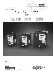
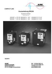
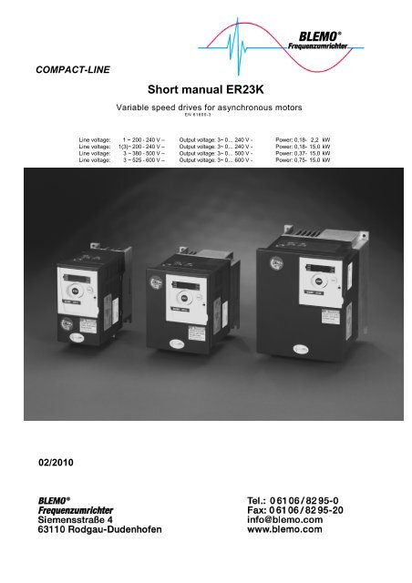
COMPACT-LINE<br />
02/2010<br />
<strong>Short</strong> <strong>manual</strong> <strong>ER23K</strong><br />
Variable speed drives for asynchronous motors<br />
EN 61800-3<br />
Line voltage: 1 ~ 200 - 240 V – Output voltage: 3~ 0 ... 240 V - Power: 0,18- 2,2 kW<br />
Line voltage: 1(3)~ 200 - 240 V – Output voltage: 3~ 0 ... 240 V - Power: 0,18- 15,0 kW<br />
Line voltage: 3 ~ 380 - 500 V – Output voltage: 3~ 0 ... 500 V - Power: 0,37- 15,0 kW<br />
Line voltage: 3 ~ 525 - 600 V – Output voltage: 3~ 0 ... 600 V - Power: 0,75- 15,0 kW
Contents<br />
Important Information 4<br />
Before you begin 5<br />
Steps for setting up (also refer to Quick Start) 7<br />
Mounting 8<br />
Wiring 10<br />
Power terminals 13<br />
Control terminals 16<br />
Electromagnetic compatibility (EMC) 19<br />
Check list 21<br />
Factory Configuration 22<br />
Programming 24<br />
Migration ER22 - <strong>ER23K</strong> 40<br />
Diagnostic and troubleshooting 41<br />
Wiring/Evaluation of PTC 45<br />
02/2010 3
Important Information<br />
NOTICE<br />
Read these instructions carefully, and look at the equipment to become familiar with the device before trying to<br />
install, operate, or maintain it. The following special messages may appear throughout this documentation or on<br />
the equipment to warn of potential hazards or to call attention to information that clarifies or simplifies a<br />
procedure.<br />
The addition of this symbol to a Danger or Warning safety label indicates that an electrical hazard exists,<br />
which will result in personal injury if the instructions are not followed.<br />
This is the safety alert symbol. It is used to alert you to potential personal injury hazards. Obey all safety<br />
messages that follow this symbol to avoid possible injury or death.<br />
PLEASE NOTE<br />
The word "drive" as used in this <strong>manual</strong> refers to the controller portion of the adjustable speed drive as defined<br />
by NEC.<br />
Electrical equipment should be installed, operated, serviced, and maintained only by qualified personnel. No<br />
responsibility is assumed by BLEMO for any consequences arising out of the use of this product.<br />
© 2009 BLEMO. All Rights Reserved.<br />
DANGER<br />
DANGER indicates an imminently hazardous situation, which, if not avoided, will result in death or<br />
serious injury.<br />
WARNING<br />
WARNING indicates a potentially hazardous situation, which, if not avoided, can result in death, serious<br />
injury or equipment damage.<br />
CAUTION<br />
CAUTION indicates a potentially hazardous situation, which, if not avoided, can result in injury or<br />
equipment damage.<br />
CAUTION<br />
CAUTION, used without the safety alert symbol, indicates a potentially hazardous situation which, if not<br />
avoided, can result in equipment damage.<br />
4 02/2010
Before you begin<br />
Read and understand these instructions before performing any procedure with this drive.<br />
DANGER<br />
HAZARD OF ELECTRIC SHOCK, EXPLOSION, OR ARC FLASH<br />
• Read and understand this <strong>manual</strong> before installing or operating the <strong>ER23K</strong> drive. Installation,<br />
adjustment, repair, and maintenance must be performed by qualified personnel.<br />
• The user is responsible for compliance with all international and national electrical code requirements<br />
with respect to grounding of all equipment.<br />
• Many parts of this drive, including the printed circuit boards, operate at the line voltage. DO NOT<br />
TOUCH. Use only electrically insulated tools.<br />
• DO NOT touch unshielded components or terminal strip screw connections with voltage present.<br />
• DO NOT short across terminals PA/+ and PC/– or across the DC bus capacitors.<br />
• Before servicing the drive:<br />
- Disconnect all power, including external control power that may be present.<br />
- Place a “DO NOT TURN ON” label on all power disconnects.<br />
- Lock all power disconnects in the open position.<br />
- WAIT 15 MINUTES to allow the DC bus capacitors to discharge. Then follow the “Bus Voltage<br />
Measurement Procedure” in the installation <strong>manual</strong> to verify that the DC voltage is less than 42 V.<br />
The drive LEDs are not indicators of the absence of DC bus voltage.<br />
• Install and close all covers before applying power or starting and stopping the drive.<br />
Failure to follow these instructions will result in death or serious injury.<br />
DANGER<br />
UNINTENDED EQUIPMENT OPERATION<br />
• Read and understand this <strong>manual</strong> before installing or operating the <strong>ER23K</strong> drive.<br />
• Any changes made to the parameter settings must be performed by qualified personnel.<br />
Failure to follow these instructions will result in death or serious injury.<br />
WARNING<br />
DAMAGED DRIVE EQUIPMENT<br />
Do not operate or install any drive or drive accessory that appears damaged.<br />
Failure to follow these instructions can result in death, serious injury, or equipment damage.<br />
02/2010 5
WARNING<br />
LOSS OF CONTROL<br />
• The designer of any control scheme must consider the potential failure modes of control paths and, for<br />
certain critical control functions, provide a means to achieve a safe state during and after a path failure.<br />
Examples of critical control functions are emergency stop and overtravel stop.<br />
• Separate or redundant control paths must be provided for critical control functions.<br />
• System control paths may include communication links. Consideration must be given to the implications<br />
of unanticipated transmission delays or failures of the link. a<br />
Failure to follow these instructions can result in death, serious injury, or equipment damage.<br />
a.<br />
For additional information, refer to NEMA ICS 1.1 (latest edition), “Safety Guidelines for the Application,<br />
Installation, and Maintenance of Solid State Control”<br />
and to NEMA ICS 7.1 (latest edition), “Safety Standards for Construction and Guide for Selection, Installation<br />
and Operation of Adjustable-Speed Drive Systems.”<br />
6 02/2010
Steps for setting up (also refer to Quick Start)<br />
1. Receive and inspect the drive<br />
• Check that the catalog number printed on the label is the same as that on the purchase<br />
order.<br />
• Remove the Altivar from its packaging and check that it has not been damaged in<br />
transit.<br />
Steps 2 to 4 must<br />
be performed with<br />
the power off.<br />
2. Check the line voltage<br />
• Check that the voltage range of the drive is compatible with the line voltage<br />
(see installation <strong>manual</strong>).<br />
3. Mount the drive<br />
• Mount the drive in accordance with the instructions in this document,<br />
page 8.<br />
• Install any options required (see option documentation).<br />
4. Wire the drive page 10<br />
• Connect the motor, ensuring that its connections correspond<br />
to the voltage.<br />
• Connect the line supply, after making sure that the power is<br />
off.<br />
• Connect the control part.<br />
5. Configure the drive (see programming<br />
<strong>manual</strong>)<br />
• Apply input power to the drive, but do not give a run<br />
command.<br />
• Set the motor parameters in [MOTOR CONTROL]<br />
(drC-) menu if the factory configuration of the drive is not<br />
suitable and especialy if the motor power doesn't<br />
correspond to the drive power. See page 32.<br />
• Set the parameters ACC, dEC, LSP, HSP and ItH in the<br />
[SETTINGS] (SEt-) menu page 29<br />
• Perform an auto-tuning.<br />
6. Start<br />
• Before start, check that there is no risk for person<br />
and material.<br />
• If possible, start without load and with low speed.<br />
02/2010 7
Mounting<br />
Mounting and temperature conditions<br />
Install the unit vertically, at ± 10°.<br />
Do not place it close to heating elements.<br />
Leave sufficient free space so that the air required for cooling purposes can<br />
circulate from the bottom to the top of the unit.<br />
≥ 50 mm<br />
≥ 50 mm<br />
Removing the vent cover<br />
Free space in front of unit: 10 mm (0.39 in.) minimum.<br />
When IP20 protection is adequate, we recommend that the vent cover on the top<br />
of the drive be removed, as shown below.<br />
Example ER23-1.1/3K<br />
8 02/2010
Mounting types<br />
3 types of mounting are possible:<br />
Type A<br />
mounting:<br />
Type B<br />
mounting:<br />
Type C<br />
mounting:<br />
Free space < 50 mm (2 in.) on each side, with vent cover fitted. Mounting type A is suitable<br />
for drive operation at surrounding air temperature less or equal to 50°C (122°F).<br />
u 50 mm<br />
2 in.<br />
Drives mounted side-by-side, vent cover should be removed (the degree of protection<br />
becomes IP20).<br />
Free space < 50 mm (2 in.) on each side. Vent cover should be removed for operation at<br />
surrounding air temperature above 50°C (122°F). The degree of protection becomes IP20.<br />
u 50 mm<br />
2 in.<br />
u 50 mm<br />
2 in.<br />
u 50 mm<br />
2 in.<br />
Note: For switching frequencies above 4 kHz and derating conditions, refer to the Installation <strong>manual</strong> for<br />
guidelines.<br />
02/2010 9
Wiring<br />
Power and circuit protection<br />
The drive must be grounded to conform with the regulations concerning high leakage currents (over 3.5 mA).<br />
Where local and national codes require upstream protection by means of a residual current device, use a type A<br />
device for single-phase drives and a type B device for three-phase drives as defined in the IEC Standard 60755.<br />
Choose a suitable model integrating:<br />
• High frequency current filtering,<br />
• A time delay that helps to prevent tripping caused by the load from stray capacitance on power-up.<br />
The time delay is not possible for 30 mA devices; in this case, choose devices with immunity against nuisance<br />
tripping.<br />
If the installation includes several drives, provide one "residual current device" per drive.<br />
Keep the power cables separate from circuits in the installation with low-level signals (detectors, PLCs,<br />
measuring apparatus, video, telephone).<br />
If you are using cables longer than 50 m (164 ft) between the drive and the motor, add output filters.<br />
Control<br />
Keep the control circuits away from the power cables. For control and speed reference circuits, we recommend<br />
using shielded twisted cables with a pitch of between 25 and 50 mm (1 and 2 in.), connecting the shielding to<br />
ground at each end.<br />
Equipment Grounding<br />
Ground the drive according to local and national code requirements. A minimum wire size of 10 mm² (6 AWG)<br />
may be required to meet standards limiting leakage current.<br />
DANGER<br />
HAZARD OF ELECTRIC SHOCK, EXPLOSION, OR ARC FLASH<br />
• The drive panel must be properly grounded before power is applied.<br />
• Use the provided ground connecting point as shown in the figure below.<br />
Failure to follow these instructions will result in death or serious injury.<br />
• Ensure that the resistance of the ground is one ohm or less.<br />
• When grounding several drives, you must connect each one<br />
directly, as shown in the figure to the left.<br />
• Do not loop the ground cables or connect them in series.<br />
10 02/2010
General wiring diagram<br />
WARNING<br />
RISK OF DRIVE DESTRUCTION<br />
• The drive will be damaged if input line voltage is applied to the output terminals (U/T1,V/T2,<br />
W/T3).<br />
• Check the power connections before energizing the drive.<br />
• If replacing another drive, verify that all wiring connections to the <strong>ER23K</strong> drive comply with wiring<br />
instructions in this <strong>manual</strong>.<br />
Failure to follow these instructions can result in death, serious injury, or equipment damage.<br />
WARNING<br />
INADEQUATE OVERCURRENT PROTECTION<br />
• Overcurrent protective devices must be properly coordinated.<br />
• The Canadian Electrical Code and the National Electrical Code require branch circuit protection. Use<br />
the fuses recommended in the installation <strong>manual</strong>.<br />
• Do not connect the drive to a power feeder whose short-circuit capacity exceeds the drive short-circuit<br />
current rating listed in the installation <strong>manual</strong>.<br />
Failure to follow these instructions can result in death, serious injury, or equipment damage.<br />
U1<br />
R / L1<br />
R / L1<br />
U / T1<br />
(1)<br />
V1<br />
S / L2<br />
S / L2<br />
V / T2<br />
W1<br />
M<br />
3 a<br />
T / L3<br />
R1A<br />
W / T3<br />
(1)<br />
ER23-...K<br />
Single phase supply<br />
ER23-.../3K/4K/6K<br />
3-phase supply<br />
R1C<br />
(2)<br />
P0<br />
R1B<br />
(3)<br />
PA / +<br />
R2A<br />
PB<br />
Braking<br />
resistor<br />
(if used)<br />
R2C<br />
PC / -<br />
CLI<br />
LI1<br />
+10<br />
LI2<br />
AI1<br />
LI3<br />
COM<br />
Reference<br />
potentiometer<br />
LI4<br />
LI5<br />
AI3<br />
X - Y mA<br />
0 + 10 V<br />
LI6<br />
AI2<br />
24V<br />
AOV<br />
AOC<br />
Use of the<br />
analog output<br />
as a logic output<br />
(1) Line choke, if used (single phase or 3-phase)<br />
(2) Relay contacts for remote signalling of drive status<br />
(3) If a braking resistor is connected, set [Dec ramp adapt.] (brA) parameter to yes (refer to the progamming<br />
<strong>manual</strong>).<br />
Note: Use interference suppressors on all inductive circuits near the drive or coupled to the same circuit<br />
(relays, contactors, solenoid valves, etc).<br />
02/2010 11<br />
COM<br />
A0C<br />
24 V relay<br />
or<br />
24V PLC input<br />
or<br />
LED
Logic input switch<br />
This switch assigns the logic input common link to 0V, 24 V or "floating" (1).<br />
Using volt-free contacts<br />
Switch in «Source» position<br />
(factory setting)<br />
SOURCE<br />
Switch in «Sink» position<br />
DANGER<br />
UNINTENDED EQUIPMENT OPERATION<br />
• Prevent accidental grounding of logic inputs configured for sink logic. Accidental grounding can result in<br />
unintended activation of drive functions.<br />
• Protect the signal conductors against damage that could result in unintentional conductor grounding.<br />
• Follow NFPA 79 and EN 60204 guidelines for proper control circuit grounding practices.<br />
Failure to follow these instructions will result in death or serious injury.<br />
(1) To locate the switch on the terminal board, see «Access to the control terminals» page 16.<br />
SINK<br />
Using PLC transistor output<br />
Switch in CLI position<br />
12 02/2010<br />
CLI
Power terminals<br />
Access to the power terminals<br />
DANGER<br />
HAZARD OF ELECTRIC SHOCK, EXPLOSION, OR ARC FLASH.<br />
Replace the cover plate on the terminals and close the door before applying power.<br />
Failure to follow these instructions will result in death or serious injury.<br />
02/2010 13
Functions of the power terminals<br />
Terminal Function For <strong>ER23K</strong><br />
Ground terminal All ratings<br />
R/L1 - S/L2 Power supply ER23-...K<br />
R/L1 - S/L2 - T/L3 ER23-.../3K<br />
ER23-.../4K<br />
ER23-.../6K<br />
PO DC bus + polarity All ratings<br />
PA/+ Output to braking resistor (+ polarity) All ratings<br />
PB Output to braking resistor All ratings<br />
PC/- DC bus - polarity All ratings<br />
U/T1 - V/T2 - W/T3 Outputs to the motor All ratings<br />
Characteristics of the power terminals<br />
ER23- Applicable wire<br />
size (1)<br />
mm 2 (AWG)<br />
Recommended<br />
wire size (2)<br />
mm 2 (AWG)<br />
(1) The value in bold corresponds to the minimum wire gauge to permit secureness.<br />
(2) 75°C (167 °F) copper cable (minimum wire size f or rated use).<br />
(3) Recommended value.<br />
Tightening<br />
torque (3)<br />
N·m (lb.in)<br />
0..../3K, 0....K 2.5 (14) 2,5 (14) 0.8 (7.1)<br />
1.1/3K, 1.5/3K, 0.../4K, 1.1/4K, 1.5/4K, 0.75/6K,<br />
1.5/6K<br />
2.5 to 6 (14 to 10) 2,5 (14) 0.8 (7.1)<br />
1.1K, 1.5K, 2.2/3K 2.5 to 6 (12 to 10) 3.5 (12) 1.2 (10.7)<br />
3.0/3K, 4.0/3K 2.5 to 6 (14 to 10) 6 (10) 1.2 (10.7)<br />
2.2/4K, 3.0/4K, 2.2/6K, 4.0/6K 2.5 to 6 (14 to 10) 2,5 (14) 1.2 (10.7)<br />
4.0/4K, 2.2K 4 to 6 (12 to 10) 4 (12) 1.2 (10.7)<br />
5.5/3K 10 to 16 (8 to 6) 10 (8) 2.5 (22.3)<br />
7.5/3K 10 to 16 (8 to 6) 16 (6) 2.5 (22.3)<br />
7.5/4K 10 to 16 (8 to 6) 16 (8) 2.5 (22.3)<br />
5.5/4K, 5.5/6K, 7.5/6K 6 to 10 (10 to 6) 6 (10) 2.5 (22.3)<br />
11.0/3K, 15.0/3K 20 to 25 (4 to 3) 20 (4) 4.5 (40.1)<br />
15.0/4K 16 to 25 (6 to 3) 16 (6) 4.5 (40.1)<br />
11.0/4K, 11.0/6K, 15.0/6K 10 to 25 (8 to 3) 10 (8) 4.5 (40.1)<br />
14 02/2010
Arrangement of the power terminals<br />
ER23-0.../3K<br />
R/L1 S/L2 T/L3<br />
P0 PA/+ PB PC/- U/T1 V/T2 W/T3<br />
ER23-1.1/3K to 4.0/3K, 0.../4K, 1.1/4K to 4.0/4K, 1.5/<br />
6K to 4.0/6K, 0.75/6K<br />
R/L1 S/L2 T/L3<br />
P0 PA/+ PB PC/- U/T1 V/T2 W/T3<br />
ER23-5.5/3K, 7.5/3K, 5.5/4K, 7.5/4K, 5.5/6K, 7.5/6K<br />
R/L1 S/L2 T/L3 P0 PA/+ PB PC/- U/T1 V/T2 W/T3<br />
ER23-11.0/3K, 15.0/3K, 11.0/4K, 15.0/4K, 11.0/6K, 15.0/6K<br />
R/L1 S/L2 T/L3 P0 PA/+ PB PC/- U/T1 V/T2 W/T3<br />
ER23-0...K<br />
R/L1 S/L2<br />
P0 PA/+ PB PC/- U/T1 V/T2 W/T3<br />
ER23-1.1K, 1.5K, 2.2K<br />
R/L1 S/L2<br />
P0 PA/+ PB PC/- U/T1 V/T2 W/T3<br />
02/2010 15
Control terminals<br />
Access to the control terminals<br />
Logic input<br />
configuration<br />
switch<br />
RJ45<br />
connector<br />
Source<br />
CLI<br />
SINK<br />
COM<br />
AI1<br />
10V<br />
AI2<br />
AI3<br />
COM<br />
AOV<br />
AOC<br />
LI4<br />
LI5<br />
LI6<br />
CLI<br />
24V<br />
LI1<br />
DANGER<br />
UNINTENDED EQUIPMENT OPERATION<br />
• Do not plug or unplug the terminal board while drive is powered.<br />
• Check the tightening of the fixing screw after any manipulation on the terminal board.<br />
Failure to follow these instructions will result in death or serious injury.<br />
DANGER<br />
HAZARD OF ELECTRIC SHOCK, EXPLOSION, OR ARC FLASH<br />
Do not touch the terminal board before :<br />
- removing power on the drive,<br />
- removing any voltage on input and output terminals.<br />
Failure to follow these instructions will result in death or serious injury.<br />
RJ45<br />
R1A<br />
R1B<br />
R1C<br />
R2A<br />
16 02/2010<br />
R2C<br />
LI2<br />
LI3<br />
Control terminals
Arrangement of the control terminals<br />
<strong>ER23K</strong> Control terminals Applicable wire size (1)<br />
mm² (AWG)<br />
R1A, R1B, R1C, R2A, R2C 0.75 to 2.5 (18 to 14)<br />
Other terminals 0.14 to 2.5 (26 to 16)<br />
Tightening torque (2)<br />
N·m (lb.in)<br />
0.5 to 0.6 (4.4 to 5.3)<br />
(1) The value in bold corresponds to the minimum wire gauge to permit secureness.<br />
(2) Recommended to maximum value.<br />
Characteristics and functions of the control terminals<br />
Terminal Function Electrical characteristics<br />
R1A<br />
R1B<br />
R1C<br />
R2A<br />
R2C<br />
Common point C/O contact<br />
(R1C) of programmable relay<br />
R1<br />
N/O contact of programmable<br />
relay R2<br />
• Minimum switching capacity: 10 mA for 5 VDC<br />
• Maximum switching capacity on resistive load (cos ϕ = 1 and<br />
L/R= 0 ms):<br />
5 A for 250 VAC and 30 VDC<br />
• Maximum switching capacity on inductive load (cos ϕ = 0.4 and<br />
L/R = 7 ms):<br />
1.5 A for 250 VAC and 30 VDC<br />
• Sampling time 8 ms<br />
• Service life: 100,000 operations at maximum switching power<br />
1,000,000 operations at minimum switching power<br />
COM Analog I/O common 0 V<br />
AI1 Analog input voltage Analog input 0 + 10 V (maximum safe voltage 30 V)<br />
• Impedance 30 kΩ<br />
• Resolution 0.01 V, 10-bit converter<br />
• Precision ± 4.3%, linearity ± 0.2%, of maximum value<br />
• Sampling time 8 ms<br />
• Operation with shielded cable 100 m maximum<br />
10 V Power supply for reference<br />
potentiometer<br />
+10 V (+ 8% - 0%), 10 mA max, protected against short-circuits and<br />
overloads<br />
AI2 Analog input voltage Bipolar analog input 0 ± 10 V (maximum safe voltage ± 30 V)<br />
The + or - polarity of the voltage on AI2 affects the direction of<br />
the setpoint and therefore the direction of operation.<br />
• Impedance 30 kΩ<br />
• Resolution 0.01 V, 10-bit + sign converter<br />
• Precision ± 4.3%, linearity ± 0.2%, of maximum value<br />
• Sampling time 8 ms<br />
• Operation with shielded cable 100 m maximum.<br />
AI3 Analog input current Analog input X - Y mA. X and Y can be programmed from 0 to<br />
20 mA<br />
• Impedance 250 Ω<br />
• Resolution 0.02 mA, 10-bit converter<br />
• Precision ± 4.3%, linearity ± 0.2%, of maximum value<br />
• Sampling time 8 ms<br />
COM Analog I/O common 0 V<br />
02/2010 17
AOV<br />
AOC<br />
Analog output voltage AOV<br />
or<br />
Analog output current AOC<br />
or<br />
Logic output voltage AOC<br />
AOV or AOC can be assigned<br />
(either, but not both)<br />
Analog output 0 to 10 V, minimum load impedance 470 Ω<br />
or<br />
Analog output X - Y mA. X and Y can be programmed from 0 to<br />
20 mA,<br />
Maximum load impedance 800 Ω<br />
• Resolution 8 bits (1)<br />
• Precision ± 1% (1)<br />
• Linearity ± 0.2% (1)<br />
• Sampling time 8 ms<br />
This analog output can be configured as a 24 V logic output on<br />
AOC, minimum load impedance 1.2 kΩ<br />
(1) Characteristics of digital/analog converter.<br />
24 V Logic input power supply + 24 V protected against short-circuits and overloads, minimum<br />
19 V, maximum 30 V<br />
Maximum customer current available 100 mA<br />
LI1<br />
LI2<br />
LI3<br />
LI4<br />
LI5<br />
LI6<br />
Logic inputs Programmable logic inputs<br />
• + 24 V power supply (maximum 30 V)<br />
• Impedance 3.5 kΩ<br />
• State 0 if < 5 V, state 1 if > 11 V (voltage difference between LI-<br />
and CLI)<br />
• Sampling time 4 ms<br />
CLI Logic input common See page 12.<br />
RJ45 Communication port Connection for SoMove software, Modbus and CANopen network,<br />
remote display, loader tools<br />
18 02/2010
Electromagnetic compatibility (EMC)<br />
Principle<br />
• Grounds between the drive, motor and cable shielding must have "high frequency" equipotentiality.<br />
• Use shielded cables with shielding connected to ground at both ends of the motor cable 6 page 20, braking<br />
resistor (if used) 8 page 20, and control-signalling cables 7 page 20. Metal ducting or conduit can be used for<br />
part of the shielding length provided that there is no break in continuity.<br />
• Ensure maximum separation between the power supply cable (line supply) and the motor cable.<br />
Installation diagram (examples)<br />
Installation depends on the drive size. The table below gives the size according to the reference.<br />
Size 1 Size 2 Size 3 Size 4 Size 5 Size 6 Size 7<br />
0.18/3K,<br />
0.37/3K<br />
0.55/3K,<br />
0.75/3K<br />
Size 8 Size 9<br />
5.5/3K,<br />
7.5/3K,<br />
5.5/4K,<br />
7.5/4K,<br />
5.5/6K,<br />
7.5/6K<br />
11.0/3K,<br />
15.0/3K,<br />
11.0/4K,<br />
15.0/4K,<br />
11.0/6K,<br />
15.0/6K<br />
0.18K,<br />
0.37K<br />
0.55K,<br />
0.75K<br />
1.1/3K,<br />
1.5/3K<br />
The corresponding installation diagrams are given on the following page.<br />
1.1K,<br />
1.5K,<br />
2.2/3K,<br />
0.37/4K,<br />
0.55/4K,<br />
0.75/4K,<br />
1.1/4K,<br />
1.5/4K,<br />
0.75/6K,<br />
1.5/6K<br />
2.2K,<br />
3.0/3K,<br />
4.0/3K,<br />
2.2/4K,<br />
3.0/4K,<br />
4.0/4K,<br />
2.2/6K,<br />
4.0/6K<br />
02/2010 19
Sizes 1 to 4 Size 5 to 7 Size 8 Size 9<br />
1 EMC plate supplied with the drive, to be installed as indicated on the diagram<br />
2 <strong>ER23K</strong><br />
3 Non-shielded power supply wires or cable<br />
4 Non-shielded wires for relay contacts<br />
5 Attach and ground the shielding of cables 6, 7 and 8 as close as possible to the drive:<br />
- Strip the shielding.<br />
- Use stainless steel cable clamps of an appropriate size on the parts from which the shielding has been<br />
stripped, to attach them to the plate 1.<br />
The shielding must be clamped tightly to the metal plate to improve electrical contact.<br />
6 Shielded cable for motor connection with shielding connected to ground at both ends.<br />
The shielding must be continuous and intermediate terminals must be in EMC shielded metal boxes.<br />
For 0.18 to 1.5 kW drives, if the switching frequency is higher than 12 kHz, use cables with low linear<br />
capacitance: maximum 130 pF (picoFarads) per meter.<br />
7 Shielded cable for connecting the control/signalling wiring.<br />
For applications requiring several conductors, use cables with a small cross-section (0.5 mm 2 , 20 AWG).<br />
The shielding must be connected to ground at both ends. The shielding must be continuous and intermediate<br />
terminals must be in EMC shielded metal boxes.<br />
8 Shielded cable for connecting braking resistor (if used).<br />
The shielding must be continuous and intermediate terminals must be in EMC shielded metal boxes.<br />
Note:<br />
• If using an additional input filter, it should be mounted under the drive and connected directly to the line supply<br />
via an unshielded cable. Link 3 on the drive is then via the filter output cable.<br />
• The HF equipotential ground connection between the drive, motor and cable shielding does not remove the<br />
need to connect the PE ground conductors (green-yellow) to the appropriate terminals on each unit.<br />
Internal EMC filter on ER23-... and ER23-.../4K<br />
ER23-...K and <strong>ER23K</strong>-...4K drives have a built-in EMC filter. As a result they exhibit leakage current to ground.<br />
If the leakage current creates compatibility problems with your installation (residual current device or other), then<br />
you can reduce the leakage current by opening the IT jumper, see <strong>ER23K</strong> Installation <strong>manual</strong>. In this<br />
configuration EMC compliance is not guaranteed.<br />
20 02/2010
Check list<br />
Read carefully the safety information in programming, installation, simplified <strong>manual</strong>s and the catalogue. Before<br />
starting up the drive, please check the following points regarding mechanical and electrical installations, then<br />
use and run the drive.<br />
For complete documentation, refer to www.blemo.com.<br />
1. Mechanical installation<br />
• For drive mounting types and recommendations on the ambient temperature, please see the Mounting<br />
instructions on page 8 and in the installation <strong>manual</strong>.<br />
• Mount the drive vertically as specified, see the Mounting instructions on page 8 or in the installation <strong>manual</strong>.<br />
• The use of the drive must be in agreement with the environments defined by the standard 60721-3-3.<br />
• Mount the options required for your application.<br />
2. Electrical installation<br />
• Connect the drive to the ground, see Equipment Grounding on page 10 and in the installation <strong>manual</strong>.<br />
• Ensure that the input power voltage corresponds to the drive nominal voltage and connect the line supply as<br />
shown on the drawing on page 11 and in the installation <strong>manual</strong>.<br />
• Ensure to use appropriate input power fuses and circuit breaker. See Installation <strong>manual</strong>.<br />
• Wire the control terminals as required, see Control terminals on page 16 and in the installation <strong>manual</strong>.<br />
Separate the power cable and the control cable according to EMC compatibility rules.<br />
• The range ER23-...K and ER23-.../4K integrates EMC filter. The leakage current can be reduced using the IT<br />
jumper as explained in the paragraph Internal EMC filter on ER23-...K and ER23-.../4K on page 20 and in the<br />
installation <strong>manual</strong>.<br />
• Ensure that motor connections correspond to the voltage (star, delta).<br />
3. Use and run the drive<br />
• Start the drive and you will see [Standard mot. freq] (bFr) page 26 at the first power on. Check that the<br />
frequency defined by the frequency bFr (the factory setting is 50 Hz) is in accordance with the frequency of<br />
the motor.<br />
• On first power-up parameters [Ref.1 channel] (Fr1) page 26 and [2/3 wire control] (tCC) page 27 appear after<br />
bFr. These parameters should be set if you want to control the drive locally, see page «How to control the<br />
drive locally» page 39.<br />
• On subsequent power-up, rdY will be displayed on the HMI.<br />
• The [Restore config.] (FCS) function, page 36 permits you to reset the drive with factory settings.<br />
02/2010 21
Factory Configuration<br />
Drive factory setting<br />
The <strong>ER23K</strong> is factory-set for the most common operating conditions:<br />
• Display: Drive ready (rdY) with motor stopped, and motor frequency with motor running,<br />
• Logic inputs LI5 and LI6, analog input AI3, analog output AOC and relay R2 are not assigned,<br />
• Stop mode in the event of detected fault: freewheel.<br />
Code Description Value Page<br />
bFr [Standard mot. freq] 50 Hz 26<br />
tCC [2/3 wire control] 2-wire transition detection control 27<br />
UFt [U/F mot 1 selected]<br />
SVC (Sensorless flux vector control for constant torque<br />
applications)<br />
34<br />
ACC<<br />
DEC<br />
[Acceleration] [Deceleration] 3.00 seconds 29<br />
LSP [Low speed] 0 Hz 29<br />
HSP [High speed] 50 Hz 29<br />
ItH [Mot. therm. current] nominal motor current (value depending on drive rating) 29<br />
SdC1 [Auto DC inj. level 1] 0.7 x nominal drive current, for 0.5 seconds 30<br />
SFr [Switching freq.] 4 kHz 31<br />
rrS [Reverse assign.] Logic input 2 (LI2) 37<br />
PS2 [2 preset speeds] Logic input 3 (LI3) 30<br />
PS4 [4 preset speeds] Logic input 4 (LI4) 30<br />
Fr1 [Ref.1 channel] Analog input 1 (AI1) 26<br />
SA2 [Summing ref. 2] Analog input 2 (AI2) (1)<br />
r1 [R1 Assignment]<br />
Detected fault(FLt): the contact opens in the event of a<br />
detected fault (or drive off)<br />
(1)<br />
brA [Dec ramp adapt.]<br />
Automatic adaptation of the deceleration ramp in the event of<br />
overvoltage on braking<br />
(1)<br />
Atr [Automatic restart] No automatic restarting after a detected fault (1)<br />
Stt [Type of stop] Normal stop mode on deceleration ramp (rMP) (1)<br />
(1) See programming <strong>manual</strong> for more details.<br />
Check that the above values are compatible with the application. In this case, the drive can be used without<br />
changing the settings.<br />
22 02/2010
Factory Configuration (continued)<br />
ER23-...K<br />
Single phase supply<br />
ER23-/3K/4K/6K<br />
3-phase supply<br />
(1) Line choke, if used (single phase or 3-phase)<br />
(2) Relay contacts for remote signalling of drive status<br />
U1<br />
R / L1<br />
R / L1<br />
U / T1<br />
(1)<br />
V1<br />
S / L2<br />
S / L2<br />
V / T2<br />
W1<br />
M<br />
3 a<br />
T / L3<br />
R1A<br />
W / T3<br />
(1)<br />
R1C<br />
(2)<br />
P0<br />
R1B<br />
PA / +<br />
R2A<br />
02/2010 23<br />
PB<br />
R2C<br />
PC / -<br />
CLI<br />
Forward<br />
Reverse<br />
2 preset speeds<br />
4 preset speeds<br />
LI1<br />
+10<br />
LI2<br />
AI1<br />
Speed<br />
reference<br />
LI3<br />
COM<br />
LI4<br />
LI5<br />
AI3<br />
LI6<br />
Summing<br />
reference<br />
AI2<br />
24V<br />
AOV<br />
AOC<br />
COM
Programming<br />
HMI description<br />
Functions of the display and keys<br />
• Four 7-segment displays<br />
• REF LED, illuminated when<br />
rEF- menu is active<br />
• Charge LED<br />
• MON LED, illuminated when<br />
SUP- menu is active<br />
• CONF LED, illuminated when<br />
SEt, drC, I-O, CtL, FUn, FLt<br />
or COM menu is active<br />
• MODE button: When rEF-<br />
displayed, switches to SEt-<br />
menu. Otherwise, switches to<br />
rEF- menu. See page 28<br />
• RUN button: Controls motor switch-on in<br />
forward mode if parameter tCC in the I-<br />
O- menu is set to LOC page 27<br />
• 2 CANopen status LEDs<br />
• Exits a menu or parameter, or<br />
clears the displayed value to<br />
return to the previous stored<br />
value<br />
• Jog dial - Acts as a<br />
potentiometer in local mode.<br />
For navigation when turned<br />
clockwise + or<br />
counterclockwise - and<br />
selection / validation when<br />
pushed.<br />
It acts as reference<br />
potentiometer, if<br />
parameter Fr1 in the<br />
CtL- menu is set to AIU1<br />
STOP/RESET button<br />
• Used to reset faults to zero<br />
• It can be used to control motor stopping<br />
- If tCC (I-O- menu) is not set to LOC, it is a freewheel<br />
stop.<br />
- If tCC (I-O- menu) is set to LOC, stopping is on a<br />
ramp, but if injection braking is in progress, a<br />
freewheel stop takes place.<br />
Normal display, with no detected faults, and the motor not running:<br />
• : Display of the parameter selected in the [MONITORING] (SUP-) menu (default selection: motor<br />
frequency).<br />
• In current limiting mode or saturation of speed or current loop, the display flashes.<br />
• InIt: Initialization sequence<br />
• rdY: Drive ready<br />
• dCb: DC injection braking in progress<br />
• nSt: Freewheel stop<br />
• FSt: Fast stop<br />
• tUn: Auto-tuning in progress<br />
24 02/2010
Menus structure<br />
Refer to the programming <strong>manual</strong> for comprehensive menu description.<br />
Power-up Parameter selection<br />
These 3 parameters<br />
are only visible at first<br />
power up of the drive.<br />
Settings can be<br />
changed subsequently<br />
in menu:<br />
drC- for bFr<br />
CtL- for Fr1<br />
I-O- for tCC.<br />
[SPEED REFERENCE]<br />
(rEF-)<br />
[SETTINGS] (SEt-)<br />
[MOTOR CONTROL]<br />
(drC-)<br />
[INPUTS / OUTPUTS CFG]<br />
(I-O-)<br />
[COMMAND] (CtL-)<br />
[APPLICATION FUNCT.]<br />
(FUn-)<br />
[FAULT MANAGEMENT]<br />
(FLt-)<br />
[COMMUNICATION]<br />
(COM-)<br />
[MONITORING] (SUP-)<br />
See<br />
programming<br />
<strong>manual</strong><br />
1 flash<br />
(save)<br />
A dash appears after menu codes to differentiate them from parameter codes. Example: [SETTINGS] (SEt-)<br />
menu, ACC parameter.<br />
02/2010 25
Configuration of the bFr, Fr1 and tCC parameters<br />
bFr, Fr1 and tCC parameters can only be modified in stop mode with the drive locked.<br />
Code Name/Description Factory<br />
settings<br />
bFr [Standard mot. freq] [50Hz IEC] (50)<br />
50<br />
60<br />
This parameter is only visible the first time the drive is switched on.<br />
It can be modified subsequently in the [MOTOR CONTROL] (drC-) menu if required.<br />
• [50Hz IEC] (50) 50 Hz: IEC<br />
• [60Hz NEMA] (60) 60 Hz: NEMA<br />
This parameter modifies the presets of the following parameters: HSP page 29, Ftd page 30,<br />
FrS page 32 and tFr page 34.<br />
Fr1 [Ref.1 channel] [AI1] (AI1)<br />
AI1<br />
AI2<br />
AI3<br />
AIU1<br />
UPdt<br />
UPdH<br />
LCC<br />
Ndb<br />
nEt<br />
This parameter is only visible the first time the drive is switched on.<br />
It can be modified subsequently in the [COMMAND] (CtL-) menu if required.<br />
• [AI1] (AI1) Analog input AI1<br />
• [AI2] (AI2) Analog input AI2<br />
• [AI3] (AI3) Analog input AI3<br />
• [Network AI] (AIV1) Jog dial. In keypad control mode the jog dial acts as a potentiometer.<br />
If LAC = L2 or L3, the following additional assignments are possible:<br />
• [+/-Speed] (UPdt) + speed/- speed via LI1<br />
• [+/-spd HMI] (UPdH) + speed/- speed via the drive jog dial or the remote keypad. For<br />
operation, display the frequency rFr.<br />
If LAC = L3, the following additional assignments are possible:<br />
• [HMI] (LCC) Reference via the remote keypad display, [HMI Frequency ref.] (LFr) parameter<br />
in the [SETTINGS] (SEt-) menu, see programming <strong>manual</strong>.<br />
• [Modbus] (Mdb) Reference via Modbus.<br />
• [Network] (nEt) Reference via communication protocol other than Modbus.<br />
26 02/2010
Code Name/Description Factory<br />
settings<br />
tCC<br />
3C<br />
LOC<br />
[2/3 wire control] [2 wire] (2C)<br />
This parameter is only visible the first time the drive is switched on.<br />
It can be modified subsequently in the [INPUTS / OUTPUTS CFG] (I-O-) menu if required.<br />
2C • [2 wire] (2C) 2-wire control: The open or closed state of the input controls running or<br />
stopping.<br />
Wiring example:<br />
2 s LI1: forward<br />
LIx: reverse<br />
24 V LI1 LIx<br />
2 s<br />
• [3 wire] (3C) 3-wire control (pulse control): A "forward" or "reverse" pulse is sufficient to<br />
control starting, a "stop" pulse is sufficient to control stopping. Refer to the programming<br />
<strong>manual</strong>.<br />
Wiring example:<br />
LI1: stop<br />
LI2: forward<br />
LIx: reverse<br />
24 V LI1 LI2 LIx<br />
• [Local] (LOC) Local control (drive or remote keypad RUN/STOP/RESET).<br />
DANGER<br />
UNINTENDED EQUIPMENT OPERATION<br />
When [2/3 wire control] (tCC) assignment is modified, the following parameters [Reverse<br />
assign.] (rrS), [2 wire type] (tCt) and all functions affecting logic inputs will return to their<br />
factory setting value.<br />
Check that this change is compatible with the wiring diagram used.<br />
Failure to follow these instructions will result in death or serious injury.<br />
To change the assignment of this parameter press the “ENT” key for 2 s.<br />
02/2010 27
[SPEED REFERENCE] (rEF-)<br />
[SPEED REFERENCE] (rEF-) menu displays LFr, AIU1 or FrH depending on reference channel active. Refer<br />
to the programming <strong>manual</strong> for further details.<br />
When local control is enabled, the jog dial of the HMI acts as a potentiometer to change the reference value up<br />
and down within the limits preset by other parameters [Low speed] (LSP) and [High speed] (HSP).<br />
If local command mode is disabled, using [Cmd channel 1] (Cd1), only reference values and units are displayed.<br />
The value will be "read only" and cannot be modified by the jog dial (the reference is no longer given by the jog<br />
dial but from an AI or other source).<br />
Actual reference displayed depends on choice made by [Ref. 1 channel] (Fr1).<br />
Code Name/Description Adjustment<br />
range<br />
LFr [HMI Frequency ref.] 0 to 500 Hz<br />
This parameter only appears if the function has been enabled.<br />
Enables modification of the speed reference with remote keypad.<br />
It is not necessary to press ENT key to validate modification of the reference.<br />
AIU1 [Image input AIV1] 0 to 100%<br />
Enables modification of the speed reference with jog dial.<br />
FrH [Frequency ref.] LSP to HSP<br />
Hz<br />
Frequency reference before ramp (absolute value).<br />
28 02/2010
[SETTINGS] (SEt-)<br />
The adjustment parameters can be modified with the drive running or stopped.<br />
Important: It is recommended to make changes with the drive stopped. Test the changes made for proper<br />
operation before placing back into service.<br />
Code Name/Description Adjustment<br />
range<br />
ACC<br />
dEC<br />
[Acceleration]<br />
[Deceleration]<br />
according to<br />
the value of<br />
parameter Inr<br />
Defined for accelerating and decelerating between 0 and the nominal frequency<br />
[Rated motor freq.] (FrS) parameter in the [MOTOR CONTROL] (drC-) menu).<br />
Check that the value of dEC is not too low according to the load to be stopped.<br />
Factory<br />
settings<br />
LSP [Low speed] 0 to HSP 0 Hz<br />
Motor frequency at minimum reference.<br />
HSP [High speed] LSP to tFr bFR<br />
Motor frequency at maximum reference: Check that this setting is suitable for the motor and<br />
the application.<br />
ItH [Mot. therm. current] 0 to 1.5 In (1) According to<br />
drive rating<br />
Set ItH to the nominal current on the motor rating plate.<br />
Refer to the programming <strong>manual</strong> if you wish to suppress thermal protection.<br />
UFr [IR compensation] 0 to 100% 20%<br />
Used to optimize torque at very low speed (increase UFr if the torque is insufficient).<br />
Check that the value of UFr is not too high when the motor is warm (risk of instability).<br />
Note: Modifying UFt (page 34) will cause UFr to return to the factory setting (20%).<br />
FLG [FreqLoopGain] 1 to 100% 20%<br />
Parameter can only be accessed if UFt (page 34) = n or nLd.<br />
The FLG parameter adjusts the following of the speed ramp on the basis of the inertia of the<br />
machine being driven.<br />
Value too low: longer response time.<br />
Value too high: overspeed, instability.<br />
StA [Fr.Loop.Stab] 1 to 100% 20%<br />
Parameter can only be accessed if UFt (page 34) = n or nLd.<br />
Value too low: Overspeed, instability<br />
Value too high: Longer response time<br />
Used to adapt the return to steady state after a speed transient (acceleration or deceleration),<br />
according to the dynamics of the machine.<br />
Gradually increase the stability to avoid any overspeed.<br />
(1) In corresponds to the nominal drive current indicated in the catalogue and on the drive rating plate.<br />
02/2010 29<br />
3 s<br />
3 s
Code Name/Description Adjustment<br />
range<br />
Factory<br />
settings<br />
SLP [Slip compensation] 0 to 150% 100%<br />
Parameter can only be accessed if UFt (page 34) = n or nLd.<br />
Used to adjust the slip compensation value used by the motor at nominal speed.<br />
The speeds given on motor rating plates are not necessarily optimal.<br />
• If slip setting < actual slip: The motor is not rotating at the correct speed in steady state.<br />
• If slip setting > actual slip: The motor is overcompensated and the speed is unstable.<br />
tdC1 [Auto DC inj. time 1] 0.1 to 30 s 0.5 s<br />
SdC1 [Auto DC inj. level 1] 0 to 1.2 In (1) 0.7 In (1)<br />
Important: Check that the motor will withstand this current without overheating.<br />
tdC2 [Auto DC inj. time 2] 0 to 30 s 0 s<br />
SdC2 [Auto DC inj. level 2] 0 to 1.2 In (1) 0.5 In (1)<br />
JPF [Skip frequency] 0 to 500 0 Hz<br />
Prevents prolonged operation at a frequency range of ± 1 Hz around JPF. This function<br />
prevents a critical speed which leads to resonance. Setting the parameter to 0 disables the<br />
function.<br />
JF2 [Skip frequency 2] 0 to 500 0 Hz<br />
Prevents prolonged operation at a frequency range of ± 1 Hz around JF2. This function<br />
prevents a critical speed which leads to resonance. Setting the parameter to 0 disables the<br />
function.<br />
SP2 [2 preset speeds] 0.0 to 500.0 Hz 10 Hz<br />
SP3 [4 preset speeds] 0.0 to 500.0 Hz 15 Hz<br />
SP4 [8 preset speeds] 0.0 to 500.0 Hz 20 Hz<br />
CLI [Current Limitation] 0.25 to 1.5 In (1) 1.5 In (1)<br />
Used to limit the torque and temperature rise of the motor.<br />
tLS [Low speed time out] 0.0 to 999.9 s 0.0 s<br />
Following operation at LSP for a defined period, a motor stop is requested automatically. The<br />
motor restarts if the frequency reference is greater than LSP and if a run command is still<br />
present. Attention: Value 0 corresponds to an unlimited period.<br />
Ftd [Freq. threshold] 0 to 500 Hz bFr<br />
(Refer to the programming <strong>manual</strong>).<br />
(1) In corresponds to the nominal drive current indicated in the catalogue and on the drive rating plate.<br />
30 02/2010
Code Name/Description Adjustment<br />
range<br />
Factory<br />
settings<br />
ttd [Motor therm. level] 0 to 118% 100%<br />
(Refer to the programming <strong>manual</strong>).<br />
Ctd [Current threshold] 0 to 1,5 In (1) In<br />
(Refer to the programming <strong>manual</strong>).<br />
SdS [Scale factor display] 0,1 to 200 30<br />
(Refer to the programming <strong>manual</strong>).<br />
SFr [Switching freq.] 2.0 to 16 kHz 4 kHz<br />
The frequency can be adjusted to reduce the noise generated by the motor.<br />
If the frequency has been set to a value higher than 4 kHz, in the event of excessive<br />
temperature rise, the drive will automatically reduce the switching frequency and increase it<br />
again once the temperature has returned to normal.<br />
This parameter can also be accessed in the [MOTOR CONTROL] (drC-) menu page 34.<br />
(1) In corresponds to the nominal drive current indicated in the catalogue and on the drive rating plate.<br />
02/2010 31
[MOTOR CONTROL] (drC-)<br />
With the exception of tUn, which can power up the motor, parameters can only be modified when the drive is<br />
stopped and there is no run command present.Drive performance can be optimized by:<br />
• entering the values given on the motor rating plate in the drive menu,<br />
• performing an auto-tune operation (on a standard asynchronous motor).<br />
Code Name/Description Adjustment<br />
range<br />
Factory<br />
settings<br />
bFr [Standard mot. freq] - 50 Hz<br />
See page 26.<br />
UnS [Rated motor volt.] According to<br />
drive rating<br />
According to<br />
drive rating<br />
Rated motor voltage given on the nameplate. If the line voltage is less than the rated motor<br />
voltage, UnS should be set to the value of the line voltage applied to the drive terminals.<br />
FrS [Rated motor freq.] 10 to 500 Hz 50 Hz<br />
Rated motor frequency given on the nameplate. The factory setting is 50 Hz, or 60 Hz if bFr is<br />
set to 60 Hz.<br />
nCr [Rated mot. current] 0.25 to 1.5 In (1) According to<br />
drive rating<br />
Rated motor current given on the nameplate.<br />
nSP [Rated motor speed] 0 to 32760 RPM According to<br />
drive rating<br />
Rating plate value. 0 to 9999 RPM then 10.00 to 32.76 KRPM.<br />
If the nominal speed is not given on the rating plate, refer to the programming <strong>manual</strong>.<br />
COS [Motor 1 Cosinus Phi] 0.5 to 1 According to<br />
drive rating<br />
Motor cos phi given on the motor nameplate.<br />
rSC [Cold stator resist.] - [No] (nO)<br />
Leave at [No] (nO)or see programming <strong>manual</strong>.<br />
(1) In corresponds to the nominal drive current indicated in the catalogue and on the drive rating plate.<br />
32 02/2010
Code Name/Description Factory<br />
settings<br />
tUn [Auto Tuning] [No] (nO)<br />
nO<br />
YES<br />
dOnE<br />
rUn<br />
POn<br />
LI1<br />
to<br />
LI6<br />
DANGER<br />
HAZARD OF ELECTRIC SHOCK OR ARC FLASH<br />
• During auto-tuning, the motor operates at rated current.<br />
• Do not service the motor during auto-tuning.<br />
Failure to follow these instructions will result in death or serious injury.<br />
DANGER<br />
UNINTENDED EQUIPMENT OPERATION<br />
• The following parameters, must be correctly configured before starting auto-tuning:<br />
UnS, FrS, nCr, nSP and nPr or COS.<br />
• If one or more of these parameters is modified after auto-tuning has been performed,<br />
tUn will return to nO and the procedure must be repeated.<br />
Failure to follow these instructions will result in death or serious injury.<br />
• [No] (nO) Auto-tuning not performed.<br />
• [Yes] (YES) Auto-tuning is performed as soon as possible, then the parameter automatically<br />
switches to dOnE or nO in the event of a fault (the tnF fault is displayed).<br />
• [Done] (dOnE) Use of the values given the last time auto-tuning was performed.<br />
• [Drv running] (rUn) Auto-tuning is performed every time a run command is sent.<br />
• [Power on] (POn) Auto-tuning is performed on every power-up.<br />
• [LI1] (LI1) Auto-tuning is performed on the transition from 0 V 1 of a logic input assigned to<br />
this function.<br />
• [LI6] (LI6)<br />
Attention:<br />
Auto-tuning is only performed if no command has been activated. If a "freewheel stop" or "fast<br />
stop" function is assigned to a logic input, this input must be set to 1 (active at 0).<br />
Auto-tuning may last for 1 to 2 seconds. Do not interrupt; wait for the display to change to dOnE<br />
or nO.<br />
Important:<br />
During auto-tuning the motor operates at nominal current.<br />
02/2010 33
Code Name/Description Adjustment<br />
range<br />
tUS [Auto tuning state]<br />
(information only, cannot be modified)<br />
tAb<br />
PEnd<br />
PrOG<br />
FAIL<br />
dOnE<br />
(1) Parameter can also be accessed in the [SETTINGS] (SEt-) menu.<br />
Factory<br />
settings<br />
- [Not done]<br />
(tAb)<br />
• [Not done] (tAb) The default stator resistance value is used to control the motor.<br />
• [Pending] (PEnd) Auto-tuning has been requested but not yet performed.<br />
• [In Progress] (PrOG) Auto-tuning in progress.<br />
• [Failed] (FAIL) Auto-tuning was not successful.<br />
• [Done] (DonE) The stator resistance measured by the auto-tuning function is used to control<br />
the motor.<br />
UFt [U/F mot 1 selected] - [SVC] (n)<br />
L<br />
P<br />
n<br />
nLd<br />
• [Cst. torque] (L) Constant torque for motors connected in parallel or special motors.<br />
• [Var. torque] (P) Variable torque: Pump and fan applications.<br />
• [SVC] (n) Sensorless flux vector control for constant torque applications.<br />
• [Energy sav.] (nLd) Energy saving, for variable torque applications not requiring high dynamics<br />
(behaves in a similar way to the P ratio at no-load and the n ratio on load).<br />
nrd [Noise reduction] - [Yes] (YES)<br />
YES<br />
nO<br />
• [Yes] (YES) Frequency with random modulation.<br />
• [No] (nO) Fixed frequency.<br />
Random frequency modulation reduces any resonance which may occur at a fixed frequency.<br />
SFr [Switching freq.](1) 2.0 to 16 kHz 4 kHz<br />
See page 31.<br />
SrF [Speed loop filter] 10 to 500 Hz 60 Hz<br />
YES<br />
nO<br />
• [Yes] (YES) The speed loop filter is suppressed (in position control applications, this reduces<br />
the response time and the reference may be exceeded).<br />
• [No] (nO) The speed loop filter is active (prevents the reference being exceeded).<br />
��<br />
��<br />
��<br />
��<br />
��<br />
��<br />
�<br />
���<br />
� ��� ��� ��� ��� ��� �<br />
��<br />
��<br />
��<br />
��<br />
��<br />
��<br />
�<br />
���<br />
� ��� ��� ��� ��� ��� �<br />
�������� ���������<br />
tFr [Max frequency] (tFr) 10 to 500 Hz 60 Hz<br />
The factory setting is 60 Hz, or 72 Hz if [Standard mot. freq] (bFr) is set to 60 Hz.<br />
34 02/2010
Code Name/Description Factory<br />
settings<br />
SCS [Saving config.] (1) [No] (nO)<br />
nO<br />
StrI<br />
2 s<br />
• [No] (nO) Function inactive.<br />
• [Config 1] (Str1) Saves the current configuration (but not the result of auto-tuning) to<br />
EEPROM. SCS automatically switches to nO as soon as the save has been performed. This<br />
function is used to keep another configuration in reserve, in addition to the current<br />
configuration.<br />
The drive is factory set with the current configuration and the backup configuration both<br />
initialized to the factory configuration.<br />
If the remote keypad display is connected to the drive, up to four additional settings are<br />
available: FIL1, FIL2, FIL3, and FIL4. Use these selections to save up to four configurations<br />
in the remote keypad display’s EEPROM memory.<br />
SCS automatically switches to nO as soon as the save is performed.<br />
CFG [Macro configuration] [Factory set.]<br />
(Std)<br />
2 s<br />
StS<br />
Std<br />
Choice of source configuration.<br />
• [Start/Stop] (StS) Start/stop configuration.<br />
Identical to the factory configuration apart from the I/O assignments:<br />
Logic inputs:<br />
- LI1, LI2 (2 directions of operation): 2-wire transition detection control,<br />
- LI1 = forward, LI2 = reverse<br />
- LI3 to LI6: Inactive (not assigned)<br />
Analog inputs:<br />
- AI1: Speed reference 0-10 V<br />
- AI2, AI3: Inactive (not assigned)<br />
- Relay R1: The contact opens in the event of a detected fault (or drive off)<br />
- Relay R2: Inactive (not assigned)<br />
Analog output AOC: 0-20 mA inactive (not assigned)<br />
• [Factory set.] (Std) Factory configuration (see page 22).<br />
(1) SCS, CFG and FCS can be accessed from several configuration menus, but they apply to all menus and<br />
parameters.<br />
2 s<br />
DANGER<br />
UNINTENDED EQUIPMENT OPERATION<br />
Check that the selected macro configuration is compatible with the wiring diagram used.<br />
Failure to follow these instructions will result in death or serious injury.<br />
To change the assignment of this parameter press the “ENT” key for 2 s.<br />
02/2010 35
Code Name/Description Factory<br />
settings<br />
FCS [Restore config.] (1) [No] (nO)<br />
2 s<br />
nO<br />
rECI<br />
InI<br />
DANGER<br />
UNINTENDED EQUIPMENT OPERATION<br />
Check that the modification of the current configuration is compatible with the wiring diagram<br />
used.<br />
Failure to follow these instructions will result in death or serious injury.<br />
• [No] (nO) Function inactive.<br />
• [Internal] (rEC1) The current configuration becomes identical to the backup configuration<br />
previously saved by SCS = StrI.<br />
rECI is only visible if the backup has been carried out. FCS automatically switches to nO as<br />
soon as this action has been performed.<br />
• [Config. CFG] (InI) The current configuration is replaced by the configuration selected by<br />
parameter CFG (2).<br />
FCS automatically changes to nO as soon as this action has been performed.<br />
If the remote keypad display is connected to the drive, up to four additional selections are<br />
available corresponding to backup files loaded in the remote keypad display's EEPROM<br />
memory: FIL1, FIL2, FIL3, and FIL4. These selections replace the current configuration with<br />
the corresponding backup configuration in the remote keypad display. FCS automatically<br />
changes to nO as soon as this action is performed.<br />
Note: If nAd briefly appears on the display once the parameter has switched to nO, the<br />
configuration transfer is not possible and has not been performed (because the drive ratings are<br />
different, for example). If ntr briefly appears on the display once the parameter has switched to<br />
nO, a configuration transfer error has occurred and the factory settings must be restored using<br />
InI. In both cases, check the configuration to be transferred before trying again.<br />
(1) SCS, CFG and FCS can be accessed from several configuration menus, but they apply to all menus and<br />
parameters.<br />
(2) The following parameters are not modified by this function; they retain their configuration:<br />
- bFr (Standard motor frequency) page 26.<br />
- LCC (Control via remote display terminal) in the [COMMAND] (CtL-) menu. Refer to the programming<br />
<strong>manual</strong>.<br />
- COd (Terminal locking code) page 39.<br />
- The [COMMUNICATION] (COM-) menu parameters. Refer to the programming <strong>manual</strong>.<br />
- The [MONITORING] (SUP-) menu. Refer to the programming <strong>manual</strong>.<br />
2 s<br />
To change the assignment of this parameter press the “ENT” key for 2 s.<br />
36 02/2010
[INPUTS / OUTPUTS CFG] (I-O-)<br />
Parameters can only be modified when the drive is stopped and no run command is present.<br />
Code Name/Description Factory settings<br />
tCC [2/3 wire control] [2 wire] (2C)<br />
See page 27.<br />
tCt [2 wire type] (parameter only accessible if tCC = 2C) [Transition] (trn)<br />
LEL<br />
trn<br />
PFO<br />
• [Level] (LEL) State 0 or 1 is taken into account for run or stop.<br />
• [Transition] (trn) A change of state (transition or edge) is necessary to initiate operation, in<br />
order to reduce accidental restarts after an interruption of the power supply.<br />
• [Fwd priority] (PFO) State 0 or 1 is taken into account for run or stop, but the "forward" input<br />
takes priority over the "reverse" input.<br />
rrS [Reverse assign.] [LI2] (LI2)<br />
CrL3<br />
CrH3<br />
AO1t<br />
dO<br />
r1<br />
r2<br />
SCS<br />
CFG<br />
FCS<br />
nO<br />
LI1<br />
LI2<br />
LI3<br />
LI4<br />
LI5<br />
LI6<br />
If rrS = nO, reverse operation is active, by means of negative voltage on AI2 for example.<br />
• [No] (nO) Not assigned<br />
• [LI1] (LI1) Logic input LI1<br />
• [LI2] (LI2) Logic input LI2, can be accessed if tCC = 2C<br />
• [LI3] (LI3) Logic input LI3<br />
• [LI4] (LI4) Logic input LI4<br />
• [LI5] (LI5) Logic input LI5<br />
• [LI6] (LI6) Logic input LI6<br />
See the programming <strong>manual</strong>.<br />
DANGER<br />
UNINTENDED EQUIPMENT OPERATION<br />
Check that the modification of the 2 wire type control is compatible with the wiring<br />
diagram used.<br />
Failure to follow these instructions will result in death or serious injury.<br />
Identical to [MOTOR CONTROL] (drC-) menu, page 35.<br />
02/2010 37
[MONITORING] (SUP-)<br />
Parameters can be accessed with the drive running or stopped.<br />
Some functions have numerous parameters. In order to clarify programming and avoid having to scroll through<br />
lists of parameters, these functions have been grouped in sub-menus.<br />
Like menus, sub-menus are identified by a dash after their code: LIF-, for example.<br />
When the drive is running, the value displayed is that of one of the monitoring parameters. By default, the value<br />
displayed is the output frequency applied to the motor (rFr parameter). Displayed values are given as an<br />
indication. These values are not as accurate as those measured using a meter.<br />
2 s<br />
While the value of the required new monitoring parameter is being displayed, the "ENT" key must<br />
be pressed and held down a second time (for 2 seconds) to confirm the change of monitoring<br />
parameter and to store it. From then on the value of this parameter will be displayed during operation<br />
(even after the drive has been switched off).<br />
If the new choice is not confirmed by pressing the "ENT" key a second time, the drive will return to the previous<br />
parameter after it has been switched off.<br />
Note: Following a power off or loss of line supply, the drive status parameter is displayed (rdY for example). The<br />
selected parameter is displayed following a run command.<br />
Code Name/Description Variation range<br />
LFr [HMI Frequency ref.] 0 to 500 Hz<br />
This parameter only appears if the function has been enabled. Displays the speed reference<br />
coming from the remote keypad.<br />
rPI [Internal PID ref.] 0 to 100%<br />
This parameter only appears if PIF is not equal to n0.<br />
FrH [Frequency ref.] (absolute value) 0 to 500 Hz<br />
rFr [Output frequency] - 500 to + 500 Hz<br />
This parameter is also used for the +/- speed function using the display terminal or keypad.<br />
It displays and validates operation. In the event of a loss of line supply, rFr is not stored and<br />
the +/- speed function must be re-validated in the [MONITORING] (SUP-) menu.<br />
SPd [Motor speed]<br />
LCr [Motor current]<br />
OPr [Motor power]<br />
100% = Nominal motor power<br />
ULn [Mains voltage](gives the line voltage via the DC bus, motor running or stopped)<br />
tHr [Motor thermal state]<br />
100% = Nominal thermal state<br />
118% = "OLF" threshold (motor overload)<br />
38 02/2010
Code Name/Description Variation range<br />
tHd [Drv. thermal state]<br />
100% = Nominal thermal state<br />
118% = "OHF" threshold (motor overload)<br />
LFt [Last fault occurred]<br />
See Diagnostic and troubleshooting, page 41.<br />
Otr [Motor torque]<br />
100% = nominal motor torque<br />
rtH [Run time] 0 to 65530 hours<br />
Total time the motor has been powered up:<br />
0 to 9999 (hours), then 10.00 to 65.53 (kilo-hours).<br />
Can be reset to zero by the rPr parameter in the [FAULT MANAGEMENT] (FLt-) menu<br />
(Refer to the programming <strong>manual</strong>).<br />
COd [PIN code 1]<br />
tUS [Auto tuning state]<br />
See page 34.<br />
UdP [Drv.Soft.Ver]<br />
Indicates the <strong>ER23K</strong> software version. E.g.: 1102 = V1.1 IE02.<br />
LIA- [LOGIC INPUT CONF.]<br />
AIA- [ANALOG INPUTS IMAGE]<br />
Important: Refer to the programming <strong>manual</strong> for comprehensive parameter<br />
and value description.<br />
How to control the drive locally<br />
In factory setting "RUN" and jog dial are inactive. To control the drive locally, adjust the following parameters:<br />
• set [Ref.1 channel] Fr1 page 26 to AIU1 (Integrated display with jog dial),<br />
• set [2/3 wire control] tCC page 27 to LOC (local control).<br />
02/2010 39
Migration ER22K - <strong>ER23K</strong><br />
The <strong>ER23K</strong> is compatible with the ER22K latest version.<br />
Nevertheless some difference can exist between both drives. You just have to copy the old paramater in the<br />
next drive for the compatibility.<br />
Configuration transfer (using remote display or loader tool)<br />
A new parameter has been added [Select ER22 conf.] (ArE) at the end of [APPLICATION FUNCT.] (FUn-)<br />
menu. It enables, during a transfer between ER22K and <strong>ER23K</strong>, to specify the ER22 type (ER22 or ER22P).<br />
Values of [Select ER22 conf.] (ArE) parameter:<br />
• nO, factory setting, transfer between two <strong>ER23K</strong>,<br />
• 31A, transfer from ER22P to <strong>ER23K</strong>,<br />
• 31E, transfer from ER22K to <strong>ER23K</strong>.<br />
After transfer is completed, switch of and on the drive in order to initialize the configuration (parameter ArE<br />
returns to factory setting).<br />
Dimensions<br />
The only difference concerns depth. All <strong>ER23K</strong> products are 2 mm deeper.<br />
Replacing ER22P<br />
Switchover from HMI version « Europe » <strong>ER23K</strong> to ER22P<br />
To substitute easily ER22P by <strong>ER23K</strong>, a fast and simple operation will be performed by the customer to switch<br />
<strong>ER23K</strong> from “Europe” version to “Asia” version.<br />
At first power-up the 2 parameters below appear after bFr. These parameters should be set as follows:<br />
[Ref.1 channel] Fr1 page 26 set to AIU1<br />
[2/3 wire control] tCC page 27 set to LOC<br />
On subsequent power-up switchover to HMI version is still possible using the following parameters:<br />
[Ref.1 channel] Fr1 in [COMMAND] (CtL-) menu<br />
[2/3 wire control] tCC in [INPUTS / OUTPUTS CFG] (I-O-) menu<br />
Factory settings<br />
Apart control using a potentiometer factory settings between ER22P and <strong>ER23K</strong> only differ as described in the<br />
table below.<br />
Parameter ATV31ppppppA <strong>ER23K</strong><br />
[2/3 wire control] tCC Local control LOC 2C<br />
[Ref.1 channel] Fr1 Analog input AI1 AIPV AI1<br />
[Cmd channel] 1 Cd1 Local control LOC tEr<br />
[Reverse assign.] rrS nO (if tCC = LOC)) LI2<br />
[Forced local Ref.] FLOC Jog Dial AIP AIU1<br />
Important: For ER22P logic input switch was set to «Sink» position, <strong>ER23K</strong> factory setting is «Source». See<br />
page 12.<br />
40 02/2010
Diagnostic and troubleshooting<br />
Assistance with maintenance, fault display<br />
If a problem arises during setup or operation, ensure that the recommendations relating to the environment,<br />
mounting and connections have been observed.<br />
The first fault detected is stored and displayed, flashing, on the screen: the drive locks and the programmable<br />
relay (R1A -R1C or R2A - R2C) contact opens.<br />
Drive does not start, no fault displayed<br />
• If there is no display, check the power supply to the drive, the wiring of inputs AI1 and AI2 and the RJ45<br />
connection.<br />
• Other cases: refer to the programming <strong>manual</strong>.<br />
Fault detection codes which cannot be reset automatically<br />
The cause of the fault must be removed before resetting by cycling power to the drive.<br />
Code Name Possible causes Remedy<br />
bLF<br />
CrF<br />
[NETWORK<br />
FAULT]<br />
[PRECHARGE<br />
FAULT]<br />
• Brake release current not<br />
reached<br />
• Brake engage frequency bEn =<br />
nO (not adjusted) when brake<br />
logic bLC is assigned.<br />
• Load relay control fault or<br />
charging resistor damaged<br />
• Check the drive/motor connection.<br />
• Check the motor windings.<br />
• Check the Ibr setting in the FUn- menu<br />
• Carry out the recommended adjustment of<br />
bEn<br />
• Replace the drive.<br />
EEF [EEPROM FAULT] • Internal memory fault • Check the environment (electromagnetic<br />
compatibility).<br />
• Replace the drive.<br />
IF1<br />
IF2<br />
IF3<br />
IF4<br />
[INTERNAL<br />
FAULT]<br />
[INTERNAL<br />
FAULT]<br />
[INTERNAL<br />
FAULT]<br />
[INTERNAL<br />
FAULT]<br />
• Unknown range • Replace the drive.<br />
• Restart drive.<br />
• MMI card not recognized<br />
• MMI card incompatible<br />
• Display missing<br />
• EEPROM problem<br />
• Industrial EEPROM fault<br />
OCF [OVERCURRENT] • Incorrect parameters in the<br />
[SETTINGS] (SEt-) and<br />
[MOTOR CONTROL] (drC-)<br />
menus<br />
• Inertia or load too high<br />
• Mechanical locking<br />
• Contact local BLEMO representative.<br />
• Check parameters in [SETTINGS] (SEt-)<br />
and [MOTOR CONTROL] (drC-) menus<br />
• Check the size of the motor/drive/load.<br />
• Check the state of the mechanism.<br />
02/2010 41
Fault detection codes which cannot be reset automatically (continued)<br />
Code Name Possible causes Remedy<br />
SCF<br />
[MOTOR SHORT<br />
CIRCUIT]<br />
• <strong>Short</strong>-circuit or grounding at the<br />
drive output<br />
• Significant ground leakage<br />
current at the drive output if<br />
several motors are connected<br />
in parallel<br />
SOF [OVERSPEED] • Speed instability<br />
• Spinning load too important<br />
tnF<br />
[AUTO-TUNING<br />
FAULT]<br />
• Check the cables connecting the drive to<br />
the motor, and the motor insulation.<br />
• Reduce the switching frequency.<br />
• Connect chokes in series with the motor.<br />
• Check the motor, gain and stability<br />
parameters.<br />
• Add a braking resistor.<br />
• Check the size of the motor/drive/load.<br />
• Special motor or motor whose • Use the L or the P ratio (UFt page 34).<br />
power is not suitable for the drive • Check the presence of the motor during<br />
• Motor not connected to the auto-tuning.<br />
drive<br />
• If a downstream contactor is being used,<br />
close it during auto-tuning.<br />
Faults which can be reset with the automatic restart function, after the cause<br />
has disappeared<br />
These faults can also be reset by switching the drive off and on again or via a logic input.<br />
Code Name Possible causes Remedy<br />
CnF [NETWORK FAULT] • Communication fault on<br />
communication card<br />
COF [CANopen FAULT] • CANopen bus communication<br />
interrupted<br />
• Check the environment<br />
(electromagnetic compatibility).<br />
• Check the wiring.<br />
• Check the time-out.<br />
• Replace the option card.<br />
• Check the communication bus.<br />
• Refer to the product-specific<br />
documentation.<br />
EPF [EXTERNAL FAULT] • According to user • According to user<br />
ILF<br />
[INTERNAL LINK<br />
FAULT]<br />
• Communication fault between<br />
communication card and drive<br />
LFF [LOSS OF 4-20 mA] • Loss of the 4-20 mA reference<br />
on input AI3<br />
ObF [OVERBRAKING] • Braking too sudden<br />
• Driving load<br />
• Check the environment<br />
(electromagnetic compatibility).<br />
• Check the connections.<br />
• Replace the option card.<br />
• Check the connection on input AI3.<br />
• Increase the deceleration time.<br />
• Install a braking resistor if necessary.<br />
• See the brA function (refer to the<br />
programming <strong>manual</strong>).<br />
42 02/2010
Faults which can be reset with the automatic restart function, after the cause<br />
has disappeared (continued)<br />
Code Name Possible causes Remedy<br />
OHF<br />
OLF<br />
OPF<br />
OSF<br />
PHF<br />
[DRIVE<br />
OVERHEAT]<br />
[MOTOR<br />
OVERLOAD]<br />
[MOTOR PHASE<br />
LOSS]<br />
[MAINS<br />
OVERVOLTAGE]<br />
[INPUT PHASE<br />
LOSS]<br />
• Drive temperature too high • Check the motor load, the drive ventilation<br />
and the environment. Wait for the drive to<br />
cool down before restarting.<br />
• Triggered by excessive motor<br />
current<br />
• Incorrect value for parameter<br />
rSC<br />
• Loss of phase at drive output<br />
• Downstream contactor open<br />
• Motor not connected or motor<br />
power too low<br />
• Instantaneous instability in the<br />
motor current<br />
• Line voltage too high<br />
• Disturbed line supply<br />
• Failure of one phase<br />
• 3-phase <strong>ER23K</strong> used on a<br />
single phase line supply<br />
• Unbalanced load<br />
This only operates with the drive<br />
on load.<br />
SLF [MODBUS FAULT] • Modbus bus communication<br />
interrupted<br />
• Confirmation of remote<br />
terminal LCC = YES and<br />
terminal disconnected<br />
• Check the ItH setting (motor thermal<br />
protection) (page 29), check the motor<br />
load. Wait for the drive to cool down<br />
before restarting.<br />
• Re-measure rSC (page 32).<br />
• Check the connections from the drive to<br />
the motor.<br />
• If a downstream contactor is being used,<br />
set OPL to OAC (refer to the programming<br />
<strong>manual</strong>, [FAULT MANAGEMENT] (FLt-)<br />
menu).<br />
• Test on a low power motor or without a<br />
motor: set OPL to nO (refer to the<br />
programming <strong>manual</strong>, [FAULT<br />
MANAGEMENT] (FLt-) menu).<br />
• Check and optimise the UFr (page 29),<br />
UnS and nCr (page 32) parameters and<br />
perform auto-tuning with tUn (page 33).<br />
• Check the line voltage.<br />
• Check the connection and the fuses.<br />
• Use a 3-phase line supply.<br />
• Disable the fault by setting IPL = nO (refer<br />
to the programming <strong>manual</strong>).<br />
• Check the communication bus.<br />
• Refer to the product-specific<br />
documentation.<br />
• Check the display terminal connection.<br />
02/2010 43
Fault detection codes which can be reset as soon as their cause disappears<br />
Code Name Possible causes Remedy<br />
CFF<br />
CFI<br />
USF<br />
[INCORRECT<br />
CONFIG.] (CFF)<br />
[INVALID CONFIG]<br />
(CFI)<br />
[UNDERVOLTAGE]<br />
(USF)<br />
• The current configuration is<br />
incompatible.<br />
• Return to factory settings or call up the<br />
backup configuration, if it is valid. See<br />
parameter FCS in the [MOTOR<br />
CONTROL] (drC-) menu, page 36.<br />
• Invalid configuration (the • Check the configuration loaded<br />
configuration loaded in the drive previously.<br />
via the serial link is incompatible). • Load a compatible configuration.<br />
• Line supply too low<br />
• Transient voltage dip<br />
• Damaged load resistor<br />
• Check the input voltage and the<br />
voltage parameter UnS.<br />
• Replace the drive.<br />
44 02/2010
esistance<br />
(Ohm)<br />
Wiring/Evaluation of PTC<br />
Attention:<br />
look at ER23<br />
<strong>manual</strong><br />
page 88<br />
ER 23<br />
LI6 = ETF *)<br />
COM<br />
*) Attention:<br />
LI6 is shown as an example.<br />
You can use all logical inputs for „Externel Fault“ /<br />
look at <strong>manual</strong> page 88).<br />
We recommend for LI5 or LI6 because of their default<br />
values without other functions.<br />
- Releasing at about 3 kΩ, possibility of reset by logical input (LI1...LI6 to rSt) at lower values (2,9 kΩ)<br />
Please check the motor after releasing „external fault“!<br />
- No realize PTC short circuit<br />
- No use ex-protected motors!<br />
- PTC has to stand 24 V and about 8 mA.<br />
release<br />
area<br />
reset<br />
area<br />
release area<br />
in case of<br />
short circuit<br />
33
BLEMO ® Frequenzumrichter<br />
Siemensstraße 4<br />
63110 Rodgau – Dudenhofen<br />
Tel.: 06106 / 82 95-0<br />
Fax: 06106 / 82 95-20<br />
Internet: http://www.blemo.com<br />
E-Mail: info@blemo.com