
Create successful ePaper yourself
Turn your PDF publications into a flip-book with our unique Google optimized e-Paper software.
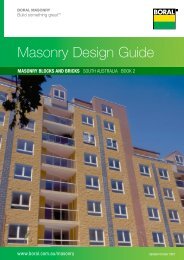
BORAL MASONRY<br />
Build something great <br />
<strong>Masonry</strong> <strong>Design</strong> <strong>Guide</strong><br />
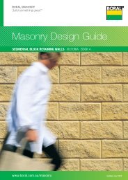
SEGMENTAL BLOCK RETAINING WALLS QUEENSLAND BOOK 4<br />
www.boral.com.au/masonry Updated July 2008
Queensland Book 4 A<br />
A Introduction<br />
Contents . . . . . . . . . . . . . . . . . . . . . . . . . . . . . . . . . . . . . . . . A2<br />
Fast Find Product and Application <strong>Guide</strong> . . . . . . . . . . . . . . . A3<br />
B Planning and <strong>Design</strong><br />
C Gardenwall ®<br />
Gardenwall Product Information . . . . . . . . . . . . . . . . . . . . . . C2<br />
Selection and Construction <strong>Guide</strong>lines . . . . . . . . . . . . . . . . . C3<br />
D Heathstone ®<br />
Heathstone Product Information . . . . . . . . . . . . . . . . . . . . . . D2<br />
Gravel-Fill Construction <strong>Guide</strong>lines . . . . . . . . . . . . . . . . . . . . D3<br />
Curved Wall Construction . . . . . . . . . . . . . . . . . . . . . . . . . . . D4<br />
Step Construction . . . . . . . . . . . . . . . . . . . . . . . . . . . . . . . . . D5<br />
E Keystone ® and Pyrmont ®<br />
Keystone Product Information . . . . . . . . . . . . . . . . . . . . . . . E4<br />
Pyrmont Product Information . . . . . . . . . . . . . . . . . . . . . . . . E5<br />
Gravel-Fill Wall Selection and Construction <strong>Guide</strong>lines . . . . . E6<br />
Typical Installation Details . . . . . . . . . . . . . . . . . . . . . . . . . . . E8<br />
F Custom Engineered Walls<br />
Engineered Retaining Walls . . . . . . . . . . . . . . . . . . . . . . . . . F2<br />
Keysteel Product Information . . . . . . . . . . . . . . . . . . . . . . . . F4<br />
Typical Soil-Anchor Application . . . . . . . . . . . . . . . . . . . . . . . F6<br />
Typical Rock-Anchor Application . . . . . . . . . . . . . . . . . . . . . . F7<br />
Typical Seawall Application . . . . . . . . . . . . . . . . . . . . . . . . . . F8<br />
PAGE<br />
An Introduction to<br />
Segmental Block Retaining Walls . . . . . . . . . . . . . . . . . . . . . B2<br />
Products @ a Glance . . . . . . . . . . . . . . . . . . . . . . . . . . . . . . . A4<br />
About This <strong>Guide</strong> . . . . . . . . . . . . . . . . . . . . . . . . . . . . . . . . . . A6<br />
Site Investigation — Preliminary <strong>Design</strong> . . . . . . . . . . . . . . . . B6<br />
Curved Walls . . . . . . . . . . . . . . . . . . . . . . . . . . . . . . . . . . . . . C4<br />
Step Tread and Cap Unit Installation . . . . . . . . . . . . . . . . . . . D5<br />
Corner Construction . . . . . . . . . . . . . . . . . . . . . . . . . . . . . . . D6<br />
No-Fines Concrete Wall Construction . . . . . . . . . . . . . . . . . . D7<br />
No-Fines Concrete Wall<br />
Construction <strong>Guide</strong>lines . . . . . . . . . . . . . . . . . . . . . . . . . . . E11<br />
Geogrid Soil-Reinforced<br />
Wall Construction <strong>Guide</strong>lines . . . . . . . . . . . . . . . . . . . . . . . E13<br />
Typical Specification for<br />
Keystone/Pyrmont Retaining Walls . . . . . . . . . . . . . . . . . . . E15<br />
Typical Terraced Wall Application . . . . . . . . . . . . . . . . . . . . . F9<br />
Typical Fencing Application . . . . . . . . . . . . . . . . . . . . . . . . . F10<br />
Typical Railing and Barrier Application. . . . . . . . . . . . . . . . . F11<br />
The information presented herein is supplied in good faith and to the best of our knowledge was accurate at the time of preparation. No responsibility can be accepted by<br />
<strong>Boral</strong> or its staff for any errors or omissions. Users are advised to make their own determination as to the suitability of this information in relation to their particular purpose<br />
and specific circumstances. Since the information contained in this document may be applied under conditions beyond our control, no responsibility can be accepted by us<br />
for any loss or damage caused by any person acting or refraining from action as a result of this information.<br />
A2 July 2008 | BORAL MASONRY DESIGN GUIDE<br />
PAGE
The quickest way to find a <strong>Boral</strong> <strong>Masonry</strong> Segmental Block Retaining Wall Solution.<br />
Simply follow the FAST FIND guide on the right hand side of the table.<br />
BORAL<br />
MASONRY<br />
SEGMENTAL<br />
BLOCK<br />
RETAINING<br />
WALLS PRODUCT<br />
Surcharge<br />
Loading<br />
Nil<br />
� 5kPa<br />
� 5kPa<br />
or<br />
� 1:4<br />
Sloped<br />
Backfill<br />
� 25kPa<br />
> 25kPa<br />
Wall Height<br />
(mm)<br />
� 1000<br />
� 1600<br />
� 3000<br />
> 3000<br />
> 6000<br />
Wall<br />
Type<br />
Vertical<br />
Set Back<br />
Vertical<br />
Set Back<br />
Property<br />
Boundary<br />
Not<br />
Boundary<br />
Vertical<br />
Set Back<br />
Vertical<br />
Set Back<br />
For technical support and sales office details please refer to the outside back cover<br />
BORAL MASONRY DESIGN GUIDE | July 2008<br />
Gardenwall<br />
Heathstone<br />
Pyrmont<br />
Keystone<br />
Keysteel<br />
D E E ✱<br />
C E ✱<br />
D ✤ E ✤ E ✤ ✱<br />
E ✤ ✱<br />
Queensland Book 4 A<br />
Core Filled Block<br />
Max. wall heights disclaimer:<br />
The gravity wall heights are maximum heights calculated in accordance with CMAA MA-53 Appendix D guidelines and a qualified engineer should confirm the suitability of the product<br />
for each intended application. As such, due consideration must be given to but not limited to:<br />
Cohesion,<br />
Dry backfill: no ingress of any water into the soil behind the retaining wall,<br />
All retaining walls are designed for zero surcharge.<br />
These walls are intended for structure Classification A walls only as defined in AS4678 Earth Retaining Structures as being where failure would result in minimal damage and loss of access.<br />
✱<br />
E ★ E ★ ✱<br />
E ★<br />
E★ E★ F<br />
F<br />
1<br />
2<br />
✤<br />
★<br />
✱<br />
Fast Find<br />
a <strong>Boral</strong><br />
Solution<br />
Select your application<br />
criteria from the left<br />
hand columns<br />
Go straight to the book<br />
section indicated by the<br />
letter at the intersection of<br />
application rows and<br />
product columns (e.g.<br />
Section E in this example)<br />
Requires ‘No-fines Concrete<br />
Backfill ’ or ‘Geogrid’ systems<br />
Requiring ‘Geogrid’ systems<br />
Please refer to Book 1, <strong>Boral</strong><br />
<strong>Masonry</strong> <strong>Design</strong> <strong>Guide</strong> and Book 2,<br />
<strong>Boral</strong> <strong>Masonry</strong> Blocks & Bricks <strong>Guide</strong><br />
A3
Queensland Que Quee<br />
een enssla<br />
lan ndd<br />
BBoo<br />
Book ook ok 4<br />
A<br />
Landscape<br />
Retaining Wall Systems<br />
for low-height domestic and commercial<br />
garden beds and retaining wall applications<br />
• Gardenwall ®<br />
<strong>Boral</strong> Gardenwall is ideal for gravity wall installations<br />
of less than 1000mm wall height. The blocks are laid<br />
with a slight set-back, and are located by a lug along<br />
the back edge. Gardenwall can also be used curved<br />
wall applications.<br />
Heathstone ® and Heathstone ® Grand<br />
<strong>Boral</strong> Heathstone retaining wall systems combine<br />
the attractive impression of natural hewn stone,<br />
the elegance of a vertical wall and the simplicity of<br />
mortarless installation. Various installation formats<br />
cater for walls up to 0.97m height. Heathstone Grand<br />
double-length blocks are particularly effective in larger<br />
installations.<br />
A4 July 2008 | BORAL MASONRY DESIGN GUIDE
Engineered<br />
Retaining Wall Systems<br />
for domestic and commercial landscaping, roadside<br />
and custom engineered retaining wall applications<br />
Keystone ®<br />
<strong>Boral</strong> Keystone walls have been proven time-andtime-again,<br />
by engineers, architects, councils, road<br />
authorities and landscapers throughout Australia.<br />
Keystone walls can cater for a wide range of<br />
applications from low height gravity walls to geogrid<br />
soil reinforced applications up to 12m wall height.<br />
Keystone walls can be constructed as near vertical<br />
with curves as tight as 1m radius, or set-back.<br />
Blocks are available in a wide selection of colours<br />
and in two splitface formats:- standard (curved) and<br />
flushface (straight).<br />
BORAL MASONRY DESIGN GUIDE | July 2008<br />
Queensland Que Qu Q eeens<br />
nsla slan and nd d Book BBoo<br />
Book<br />
k 4<br />
A<br />
Pyrmont ®<br />
<strong>Boral</strong> Pyrmont retaining walls are a modern-day link<br />
to our pioneer heritage. Pyrmont combines modern<br />
engineering versatility with the elegance of a vertical<br />
wall and the style of hand-finished natural stone.<br />
Pyrmont gravity or soil reinforced retaining wall<br />
systems can be engineered for applications up to 6m<br />
height and can accommodate gentle curves and step<br />
installations.<br />
Keysteel Custom Engineered Retaining<br />
Wall Systems<br />
<strong>Boral</strong> Keysteel is a high performance engineered<br />
retaining wall system for applications requiring wall<br />
heights in excess of 6m and/or where critical surcharge<br />
loadings are present. <strong>Boral</strong> Keysteel is an internationally<br />
proven system that integrates the superior strength<br />
and durability of Keysteel blocks with steel-ladder soilreinforcement<br />
to provide engineered solutions for the<br />
most demanding retaining structures.<br />
A5
Queensland Book 4 A<br />
<strong>Boral</strong> <strong>Masonry</strong> Product Range<br />
<strong>Boral</strong> <strong>Masonry</strong> offers a comprehensive range of proven products<br />
and systems including Segmental Block Retaining Wall<br />
Systems, Segmental Paving Products, <strong>Masonry</strong> Blocks, <strong>Masonry</strong><br />
Bricks, <strong>Masonry</strong> Fire and Acoustic Wall Systems.<br />
What’s in this <strong>Guide</strong><br />
The <strong>Boral</strong> <strong>Masonry</strong> Segmental Block Retaining Walls <strong>Guide</strong>,<br />
(this book), details a comprehensive selection of retaining wall<br />
options ranging from low height gravity landscaping walls to<br />
critically loaded reinforced-soil retaining structures.<br />
This guide has been prepared as a comprehensive <strong>Boral</strong><br />
Product Reference <strong>Guide</strong>. It does not attempt to cover all<br />
the requirements of the Codes and Standards which apply<br />
to retaining wall construction. All structural detailing should<br />
be checked and approved by a structural engineer before<br />
construction. <strong>Boral</strong> reserves the right to change the contents<br />
of this guide without notice.<br />
A <strong>Guide</strong>d Tour of a Typical Product Information Page<br />
Product pages are laid out in a consistent manner to assist with easy selection and specification<br />
of <strong>Boral</strong> <strong>Masonry</strong> products.<br />
Product Icons with<br />
dimensions for<br />
products available<br />
in your region/<br />
state<br />
Colour and<br />
Availability<br />
information<br />
for products<br />
distributed in<br />
your region/<br />
state<br />
Lifting<br />
Bars<br />
315<br />
315<br />
200<br />
200<br />
Pyrmont ® Pyrmont ®<br />
Keystone ® & Pyrmont ®<br />
A6 July 2008 | BORAL MASONRY DESIGN GUIDE<br />
BOOK<br />
4<br />
PAGE<br />
v1QLD Draft 02/02/05<br />
E5<br />
Vertical Retaining Wall System<br />
455<br />
455<br />
INTRODUCTION<br />
DESIGN CONSIDERATIONS<br />
Standard Unit<br />
Standard Unit<br />
<strong>Boral</strong> Pyrmont retaining retaining wall systems wall Suitable Suitable for curved for wall curved wall<br />
systems integrate integrate the engineering the engineering capabilities installations with with a suggested a suggested<br />
355<br />
355<br />
355<br />
355<br />
capabilities of the Keystone of the system Keystone with system the minimum minimum convex convex curve curve radius radius of<br />
with versatility the versatility and pleasing and aesthetics pleasing of of 5m (resulting in a 5mm lip).<br />
455<br />
455<br />
Premium<br />
Premium<br />
Cap<br />
Cap<br />
Rockfaced<br />
Rockfaced<br />
65<br />
65<br />
65<br />
65<br />
355<br />
355<br />
Premium<br />
Premium<br />
Corner<br />
Corner<br />
Cap<br />
Cap<br />
Rockfaced<br />
Rockfaced<br />
200<br />
200<br />
aesthetics a vertical wall. of a The vertical Pyrmont wall. unit The is a COLOURS<br />
COLOURS<br />
Pyrmont split-face block unit is with a split-face four chamfered block Please refer to colour swatch<br />
Please refer to colour swatch<br />
with edges, emulating four chamfered the care, skill edges, and information for an indication of<br />
information for an indication of<br />
emulating determination the of stone care, masons skill from and current colours.<br />
current colours.<br />
determination Australia’s early of stone settler masons period. from<br />
To reduce the possibility of staining<br />
Australia s early settler period. To reduce the possibility of staining<br />
<strong>Boral</strong> Pyrmont retaining wall system and to enable easier cleaning, a<br />
and to enable easier cleaning, a<br />
<strong>Boral</strong> is also Pyrmont suitable for retaining constructing wall system steps, masonry sealer can be applied to all<br />
masonry sealer can be applied to all<br />
is planter also suitable boxes, for gently constructing curved steps, walls visible surfaces after installation.<br />
visible surfaces after installation.<br />
planter and crisp boxes, 90° corners. gently curved walls<br />
and crisp 90¡ corners.<br />
227<br />
227 455 455<br />
455 455<br />
90¡<br />
90°<br />
Corner<br />
Corner<br />
Unit<br />
Unit<br />
Right<br />
Right<br />
or<br />
Left<br />
Left<br />
Hand<br />
Hand<br />
227<br />
227<br />
Keygrid Geogrid Geogrid Soil Soil Reinforcement<br />
Reinforcement<br />
Availability & and Colours Colours<br />
•<br />
No<br />
No<br />
minimum<br />
minimum<br />
order<br />
order<br />
quantities<br />
quantities<br />
apply.<br />
apply.<br />
•<br />
Lead<br />
Lead<br />
time<br />
time<br />
0-4<br />
0-4<br />
weeks.<br />
weeks.<br />
•<br />
Colour<br />
Colour<br />
swatch<br />
swatch<br />
is<br />
is<br />
a<br />
a<br />
guide<br />
guide<br />
only.<br />
only.<br />
Contact<br />
Contact<br />
your<br />
your<br />
nearest<br />
nearest<br />
<strong>Boral</strong><br />
<strong>Boral</strong><br />
<strong>Masonry</strong><br />
<strong>Masonry</strong><br />
sales<br />
sales<br />
office<br />
office<br />
for<br />
for<br />
a<br />
a<br />
sample.<br />
sample.<br />
Hawkesbury Yellow Yellow<br />
Pins<br />
BORAL MASONRY DESIGN GUIDE | July 2008<br />
Please note that this guide is based on products available at the<br />
time of publication from the <strong>Boral</strong> <strong>Masonry</strong> Queensland sales<br />
region. Different products and specifications may apply to <strong>Boral</strong><br />
products sourced from other regions.<br />
Specifications<br />
Specifications<br />
Additional Assistance and Information<br />
• Contact Details: Please refer to the outside back cover of<br />
this publication for <strong>Boral</strong> <strong>Masonry</strong> contact details.<br />
• Colour and Texture Variation: The supply of raw<br />
materials can vary over time. In addition, variation can<br />
occur between product types and production batches. Also<br />
please recognise that the printed colours in this brochure<br />
are only a guide. Please, always ask to see a sample of your<br />
colour/texture choice before specifying or ordering.<br />
• Terms and Conditions of Sale: For a full set of Terms<br />
and Conditions of Sale please contact your nearest <strong>Boral</strong><br />
<strong>Masonry</strong> sales office.<br />
Queensland Book 4 E<br />
Description HxLxDmm Wt kg N°/m2<br />
Standard Unit<br />
Description<br />
Premium Cap (Rockfaced 1 side)<br />
Standard Unit<br />
Premium Corner Cap<br />
Premium Cap (Rockfaced 1 side)<br />
(Rockfaced 2 sides)<br />
200x455x315 38.5 11<br />
HxLxDmm Wt kg N…/m2<br />
65x455x355 21.5 2.2/lin mtr<br />
200x455x315 38.5 11<br />
65x355x355 18.8 1/90° corner<br />
65x455x355 21.5 2.2/lin mtr<br />
Premium Corner Cap 65x355x355 18.8 1/90¡ corner<br />
90° Corner Unit (Right or Left Hand) 200x455x227 28.8 5/vertical metre<br />
(Rockfaced 2 sides)<br />
Pins 2 pins per full unit<br />
90¡ Corner Unit (Right or Left Hand) 200x455x227 28.8 5/vertical metre<br />
(high strength pultruded fibreglass)<br />
Pins<br />
Lifting Bars<br />
2 pins per full unit<br />
(Pyrmont units should be lifted by<br />
(high strength pultruded fibreglass)<br />
two people using the Keystone lifting bars)<br />
Lifting Bars (Pyrmont units should be lifted by<br />
two people using the Keystone lifting bars)<br />
E5<br />
Product Range, Book and<br />
Page Identification<br />
Product Name and other<br />
identifying features<br />
Product information<br />
relating to features,<br />
applications, and<br />
accessories<br />
Product Specifications
BORAL MASONRY<br />
Build something great <br />
<strong>Masonry</strong> <strong>Design</strong> <strong>Guide</strong><br />
SEGMENTAL BLOCK RETAINING WALLS QUEENSLAND BOOK 4<br />
B PLANNING AND DESIGN<br />
44B
Queensland Book 4 B<br />
An Introduction to Segmental<br />
Block Retaining Walls<br />
Background<br />
For many years cantilever retaining walls have been constructed<br />
with reinforced concrete masonry stems (steel reinforcement<br />
grouted into hollow concrete block work) and reinforced<br />
concrete footings. (Refer to Fig B1).<br />
Segmental block gravity retaining structures, consisting<br />
of dry-stacked concrete units which resist overturning by<br />
virtue of their own weight and setback, were introduced into<br />
Australia in the early 1990’s, and rapidly became popular. This<br />
system provides an attractive and cost effective solution, but<br />
its stability is limited by the geometry of the units and wall<br />
heights. (Refer to Fig B2).<br />
In order to achieve greater heights, reinforced-soil walls (such<br />
as <strong>Boral</strong> Keystone) were introduced. These walls typically<br />
consist of geosynthetic materials, which are placed in<br />
horizontal layers in the compacted backfill and mechanically<br />
connected to the blocks. Such systems can be constructed<br />
several metres high, and accommodate significant loads.<br />
A further development of this system is the <strong>Boral</strong> Keysteel<br />
system which utilises steel-ladder reinforcement. Here the<br />
steel-ladder reinforcement is placed in horizontal layers in<br />
the compacted backfill and mechanically connected to the<br />
blocks. These systems are individually engineer designed,<br />
and are suitable for walls in excess of 6m high and for critical<br />
surcharge loadings. (Refer to Fig B3).<br />
B2<br />
Steel reinforced<br />
and concrete<br />
grout filled<br />
hollow concrete<br />
block wall<br />
Fig B1 — Typical Reinforced Concrete <strong>Masonry</strong><br />
Cantilever Retaining Wall<br />
Reinforced<br />
concrete<br />
footings<br />
Segmental block gravity<br />
retaining structure, drystacked<br />
against a soil<br />
slope<br />
Fig B2 — Typical Segmental Block<br />
Gravity Retaining Wall<br />
Fig B3 — Typical Reinforced-Soil<br />
Segmental Block Retaining Wall<br />
Segmental<br />
concrete<br />
gravity<br />
retaining<br />
structure, with<br />
reinforced soil<br />
July 2008 | BORAL MASONRY DESIGN GUIDE
Behaviour of Segmental Block<br />
Reinforced-Soil Retaining Walls<br />
If unrestrained, a soil embankment will slump to its angle<br />
of repose. Some soils, such as clays, have cohesion that enables<br />
vertical and near-vertical faces to remain partially intact, but<br />
even these may slump under the softening influence of ground<br />
water. When an earth retaining structure is constructed, it<br />
restricts this slumping. The soil exerts an active pressure on<br />
the structure, which deflects a little and is then restrained<br />
by the friction and adhesion between the base and soil<br />
beneath, passive soil pressures in front of the structure and<br />
bearing capacity of the soil beneath the toe of the structure.<br />
If water is trapped behind the retaining structure, it exerts<br />
an additional hydraulic pressure. This ground water also reduces<br />
the adhesion and bearing resistance.<br />
If massive rock formations are present immediately behind the<br />
structure, these will restrict the volume of soil which can be<br />
mobilised and thus reduce the pressure.<br />
Reinforced-soil systems consist of a series of horizontal<br />
geogrids that have been positioned and pulled tight within<br />
a compacted soil mass, thus strengthening it and restricting its<br />
slump. The geogrids are strategically placed to intersect potential<br />
failure planes that are inclined from near the base of the wall,<br />
up at an angle (depending on the soil properties), to the top of<br />
the fill. The function of the geogrids is to ‘strengthen’ the soil<br />
mass and they are ‘anchored’ by compacted backfill beyond the<br />
potential failure planes.<br />
Local collapse and erosion of the front face is eliminated by<br />
fixing concrete segmental facing units to the exposed ends<br />
of the geogrids. However, the segmental concrete facing is<br />
not designed to ‘retain’ the strengthened soil mass, which<br />
should be able to stand independently of the facing except<br />
for local effects. The connection spacing (and the geogrid<br />
spacing) must account for the local stability of the facing,<br />
including bulging and rotation above the top geogrid. The<br />
top capping course is normally bonded to the course below<br />
using a concrete to concrete adhesive.<br />
A surface sealing layer and surface drainage system minimise<br />
the quantity of rainwater entering the soil mass. A sub-surface<br />
drainage system behind the segmental concrete facing and<br />
(sometimes) beneath the wall reduce pore water pressures and<br />
thus reduce the tendency for local or global slip.<br />
Thus, the essential features of a properly designed and constructed<br />
segmental block reinforced soil retaining wall are:<br />
• Geogrids with adequate length and strength;<br />
BORAL MASONRY DESIGN GUIDE | July 2008<br />
Queensland Book 4 B<br />
• Adequate connection to the facing to provide local<br />
stability;<br />
• A drainage system that will relieve hydro static pressures<br />
for the life of the structure.<br />
Importance of a Geotechnical Report<br />
The design of a reinforced soil retaining wall includes two<br />
essential parts:<br />
• Analysis of the proposed reinforced soil structure and<br />
the adjacent ground for global slip, settlement, drainage<br />
and similar global considerations; and<br />
• Analysis and design of the reinforced soil structure itself.<br />
These analyses must be based on an accurate and complete<br />
knowledge of the soil properties, slope stability, potential slip<br />
problems and ground water.<br />
Except in the case of simple structures, a geotechnical report<br />
by a qualified and experienced geotechnical engineer should<br />
be obtained.<br />
Such a report must address the following considerations, as well<br />
as any other pertinent points not listed.<br />
• Soil properties;<br />
• Extent and quality of any rock, including floaters and<br />
bedrock;<br />
• Global slip and other stability problems;<br />
• Bedding plane slope, particularly if they slope towards<br />
the cut;<br />
• Effect of prolonged wet weather and the consequence of<br />
the excavation remaining open for extended periods;<br />
• Effect of ground water;<br />
• Steep back slopes and the effect of terracing;<br />
• Effect of any structures founded within zone of influence.<br />
Safety and Protection of Existing<br />
Structures<br />
Whenever soil is excavated or embankments are constructed,<br />
there is a danger of collapse. This may occur through<br />
movement of the soil and any associated structures by:<br />
• Rotation around an external failure plane that encompasses<br />
the structure;<br />
• Slipping down an inclined plane;<br />
• Sliding forward, or<br />
• Local bearing failure or settlement.<br />
B3
Queensland Book 4 B<br />
These problems may be exacerbated by the intrusion of surface<br />
water or disruption of the water table, which increase pore water<br />
pressures and thus diminish the soil’s ability to stand without<br />
collapse.<br />
The safety of workers and protection of existing structures<br />
during construction must be of prime concern and should<br />
be considered by both designers and installers. All excavations<br />
should be carried out in a safe manner and in accordance with<br />
the relevant regulations, to prevent collapse that may endanger<br />
life or property. Adjacent structures must be founded either<br />
beyond or below the zone of influence of the excavation. Where<br />
there is risk of global slip, for example around a slip plane<br />
encompassing the proposed retaining wall or other structures,<br />
or where there is risk of inundation by ground water or surface<br />
water, construction should not proceed until the advice of a<br />
qualified and experienced Geotechnical Engineer has been<br />
obtained and remedial action has been carried out.<br />
Global slip failure<br />
Soil retaining structures must be checked for global slip failure<br />
around all potential slip surfaces or circles.<br />
<strong>Design</strong>ers often reduce the heights of retaining walls by splitting<br />
a single wall into two (or more) walls, thus terracing the site.<br />
Whilst this may assist in the design of the individual walls, it will<br />
not necessarily reduce the tendency for global slip failure around<br />
surfaces encompassing all or some of the retaining walls.<br />
Analysis for global slip is not included in this guide, but it is<br />
recommended that designers carry out a separate check using<br />
commercially available software.<br />
Differential Settlement<br />
The Concrete <strong>Masonry</strong> Association of Australia (CMAA)<br />
recommends that for dry stacked mortarless retaining walls<br />
employing masonry units (i.e. units with an area less<br />
than 0.2m2) on an aggregate levelling pad, the differential<br />
settlement should be limited to 1% of the length. Whilst it<br />
is permissible for the retaining wall to undergo differential<br />
settlement up to 1% of the length, it may be preferable<br />
to limit settlement to a lower figure giving consideration<br />
to aesthetics (i.e. keeping the bedding planes level), in<br />
addition to the structural considerations.<br />
Techniques to reduce or control the effects of differential<br />
settlement include:<br />
B4<br />
• Articulation of the wall (in discontinuing the normal<br />
stretcher bond) at convenient intervals along the length,<br />
or<br />
• Excavating, replacing and compacting areas of soft soil,<br />
• Limiting the stepping of the foundation and bottom course<br />
to a maximum 200mm.<br />
Unit Cracking/Gapping — Settlement<br />
Keystone modular retaining wall structures can tolerate a certain<br />
amount of settlement due to the flexible nature of the system<br />
and small individual unit size.<br />
Observation of a number of completed structures that have<br />
undergone settlement indicates that the wall’s tolerance for<br />
settlement without cracking is inversely proportional to the wall<br />
height. Lower height walls (H5m). This increased<br />
flexibility is due to lower confining forces and load transfer taking<br />
place on each block, which permits small individual movements<br />
to occur, accommodating the settlement experienced without<br />
facial distress. Taller walls place the lower wall units under<br />
considerable confining pressure, restricting unit movement and<br />
permitting shear and flexural stresses to build up to the point<br />
where a block cracks as a means of stress relief.<br />
Low wall settlement problems are typically observed in residential<br />
projects where soils adjacent to houses are uncompacted and<br />
the walls settle differentially over a short distance. Usually<br />
gapping or offset joints are visually noted and the settlement<br />
is obvious.<br />
Gapping and offset joints<br />
Fig B4 — Typical Low Wall<br />
Settlement<br />
Downward<br />
movement<br />
July 2008 | BORAL MASONRY DESIGN GUIDE
Tall wall settlement is not as obvious but occasional facial<br />
cracks can be observed in areas of flexural stress concentration,<br />
typically in small groupings in the bottom 1/3 of the wall.<br />
Settlement induced cracks are usually not structurally<br />
significant and are just a means of facial stress relief for the<br />
unreinforced dry-stack facing system. However, cracked units<br />
can be a symptom of other types of problems, so a review by<br />
an engineer is always recommended.<br />
High confining<br />
pressure<br />
Flexural stress<br />
Facial cracks<br />
Importance of Drainage<br />
Downward<br />
movement<br />
Fig B5 — Typical Tall Wall<br />
Settlement<br />
This guide assumes that a properly functioning drainage system<br />
is effective in removing hydraulic pressure. If this is not the<br />
case, the designer will be required to design for an appropriate<br />
hydraulic load.<br />
Based on an effective drainage system, it is common to use<br />
drained soil properties. For other situations, the designer<br />
must determine whether drained or undrained properties are<br />
appropriate. In particular, seawalls that may be subject to rapid<br />
drawdown (not covered in this guide) require design using<br />
undrained soil properties.<br />
BORAL MASONRY DESIGN GUIDE | July 2008<br />
Queensland Book 4 B<br />
B5
Queensland Que Quee<br />
een enssla<br />
lan ndd<br />
BBoo<br />
Book ook ok 4<br />
B<br />
Site Investigation: Preliminary <strong>Design</strong><br />
Client: __________________________________________________________________________<br />
Project: _________________________________________________________________________<br />
Location: ________________________________________________________________________<br />
Use for which retaining wall is intended: _____________________________________________<br />
Proximity of other structures to the face of the retaining wall:<br />
B6<br />
Date: _______________________<br />
Report prepared by: _______________________<br />
Structure or load Distance (m)<br />
Distance of live loads from top of wall (Dqi) _______________________<br />
Distance of dead loads from top of wall (Dqd) _______________________<br />
Distance of point loads from top of wall (Di) _______________________<br />
Distance of other structures from base of wall (Ds) _______________________<br />
Structure classification: _________________________________________________<br />
For guidance refer AS4678, Table 1.1<br />
Structure Classification Examples<br />
2. Where failure would result in significant damage or risk to life<br />
3. Where failure would result in moderate damage and loss of services<br />
4. Where failure would result in minimal damage and loss of access<br />
Required design life: _____________________________________________________<br />
For guidance refer AS4678, Table 3.1<br />
Type of Structure <strong>Design</strong> life (years) Type of Structure <strong>Design</strong> life (years)<br />
Temporary site works 5 Residential dwellings 60<br />
Mine structures 10 Minor public works 90<br />
Industrial structures 30 Major public works 120<br />
River and marine structures 60<br />
Wall geometry:<br />
Wall height above GL (H’)<br />
Embedment depth (Hemb)<br />
___________ m<br />
H/20 or 200mm ___________ m<br />
Wall slope (v) ___________ °<br />
Angle of backfill slope (b) ___________ °<br />
Height of backfill (h)<br />
Foundation material:<br />
Allowable bearing pressure<br />
___________ m<br />
Under reinforced soil block ___________ kPa<br />
Water profile:<br />
Water table depth within wall fill ___________ m<br />
Retained soil data:<br />
Soil density (g r ) ___________ kN/m 3<br />
Internal friction angle (fr ) peak ___________ °<br />
Cohesion (C* i ) ___________ kPa<br />
Loading data:<br />
Dead load surcharge (qd ) ___________ kPa<br />
Live load surcharge (ql ) ___________ kPa<br />
Horizontal line load (F) ___________ kN/m<br />
Vertical line load (P) ___________ m<br />
Width of bearing (b) ___________ m<br />
July 2008 | BORAL MASONRY DESIGN GUIDE
BORAL MASONRY<br />
Build something great <br />
<strong>Masonry</strong> <strong>Design</strong> <strong>Guide</strong><br />
SEGMENTAL BLOCK RETAINING WALLS QUEENSLAND BOOK 4<br />
C GARDENWALL ®<br />
44C
Queensland Book 4 C<br />
C2<br />
295<br />
Availability and Colours<br />
• No minimum order quantities apply.<br />
• Lead time 0-2 weeks.<br />
• Colour swatches are a guide only. Contact your<br />
nearest <strong>Boral</strong> <strong>Masonry</strong> sales office for a sample.<br />
Kota Green<br />
Paperbark<br />
203<br />
125<br />
Standard Unit<br />
295<br />
Light Sands Terrain<br />
Specifications<br />
203<br />
Portstone<br />
125<br />
Soft Split Unit<br />
Charcoal<br />
Terracotta Sunset<br />
Gardenwall ®<br />
Retaining Wall System<br />
INTRODUCTION<br />
<strong>Boral</strong> Gardenwall is ideal for low<br />
landscaping walls and edgings<br />
in garden and communal areas.<br />
Gardenwall’s rockface texture, multifaceted<br />
face and setback construction<br />
produces an aesthetically pleasing<br />
feature for landscaped areas.<br />
Gardenwall is often used for garden<br />
edges and raised beds, terraces and<br />
to create decorative features such as<br />
around pools.<br />
DESIGN CONSIDERATIONS<br />
Depending on the foundation<br />
and retained soil characteristics,<br />
Gardenwall is effective as a gravity<br />
retaining wall structure up to<br />
1000mm (maximum 8 courses).<br />
Never install where loads (e.g.<br />
buildings, driveways) will be located<br />
within 1000mm of the wall. For<br />
engineered walls (to AS4678) higher<br />
than 1000mm, or where a surcharge<br />
is present, <strong>Boral</strong> Keystone or<br />
Pyrmont walls should be considered.<br />
ADVANTAGES<br />
• Gardenwall does not require<br />
concrete foundations.<br />
• Easy installation of straight walls<br />
and curved walls.<br />
• Durable, low maintenance, longterm<br />
landscaping.<br />
• Solid units — eliminates the need<br />
for capping and corner units.<br />
COLOURS<br />
Gardenwall is offered in a range<br />
of colours to suit traditional and<br />
contemporary settings. Please refer<br />
to colour swatch information for an<br />
indication of current colours.<br />
To reduce the possibility of staining<br />
and to enable easier cleaning, a<br />
masonry sealer can be applied to all<br />
visible surfaces after installation.<br />
Product Description Finish HxLxDmm Approx Wt kg No. per m2<br />
Standard Unit Rockfaced 125x295x203 13.2 26.9<br />
Soft Split Rockfaced 125x295x203 14.95 26.9<br />
July 2008 | BORAL MASONRY DESIGN GUIDE
Selection and Construction <strong>Guide</strong>lines<br />
IMPORTANT: Please consult with the regulating council for<br />
local design requirements prior to the design and construction<br />
of a retaining wall. Councils in general require that retaining<br />
walls be designed and certified by a suitably qualified engineer<br />
where the wall is over 0.5m in height and/or where there is<br />
surcharge loading such as a roadway, house, or other structure<br />
near the wall.<br />
• <strong>Boral</strong> Gardenwall is only suitable for walls up to 1000mm<br />
in height and where no loads or surcharge exists within<br />
1000mm behind the wall.<br />
Installation<br />
• Remove the retaining lug on the base of the unit on those<br />
Gardenwall blocks being used in the base course only (this<br />
makes levelling the first course much easier). To remove<br />
the lip, place at an angle on the ground and strike the lug<br />
firmly with a hammer. (Safety glasses should be worn).<br />
• As a safety precaution to avoid lifting or movement of the<br />
top units, it is recommended that the top course units<br />
are secured using a construction adhesive. This is also<br />
recommended in areas of possible vandalism.<br />
• Standard units can also be used to construct convex<br />
curves.<br />
No loads to be located within 1000mm behind wall<br />
Backfill should be no higher than the top of the wall<br />
Native soi l<br />
BORAL MASONRY DESIGN GUIDE | July 2008<br />
350mm<br />
min.<br />
Dish drain to direct surface<br />
run-off (if required )<br />
Filter fabric to keep dirt<br />
out of drainage layer<br />
1<br />
5<br />
10 0mm min .<br />
Queensland Book 4 C<br />
Retaining Soil Type<br />
Wall Height<br />
H (mm)<br />
POOR Clay, Silt, Fine sand 750<br />
AVERAGE Coarse sand 875<br />
GOOD Gravel, Stone 1000<br />
Gardenw all Uni t<br />
Backfill placed and<br />
compacted in 250mm laye rs<br />
300mm width of 12-20mm<br />
free draining granular<br />
material eg. blue metal<br />
Drainage pipe<br />
First cou rse to be buried below<br />
final ground level (to engineer's<br />
specification - 10 0mm min. )<br />
Compacted road base levelling<br />
pad on undisturbed inor ganic soil<br />
Fig C1 — Typical Gravity Wall Construction Detail — Gardenwall<br />
Note: Refer to max. wall heights disclaimer on page A3 of this guide.<br />
The gravity wall heights are maximum heights calculated in accordance with CMAA MA-53 Appendix D guidelines and a qualified engineer should confirm<br />
the suitability of the product for each intended application.<br />
H<br />
C3
Queensland Book 4 C<br />
Curved Walls<br />
C4<br />
Minimum Radius = 666mm for top course<br />
For base course radius add 43mm<br />
for each course below<br />
Fig C2 — Construction of Curved Walls<br />
• When designing Gardenwall for convex curves to the<br />
maximum height of 8 courses, it is necessary to begin<br />
with a minimum radius of 1000mm. It may also be<br />
necessary to remove the outer portions of the retaining<br />
lug from each unit to maintain a consistent setback. It is<br />
important that the entire lug is not removed.<br />
• When building curves, some blocks may also require<br />
trimming of the length to maintain a half bond pattern.<br />
July 2008 | BORAL MASONRY DESIGN GUIDE
BORAL MASONRY<br />
Build something great <br />
<strong>Masonry</strong> <strong>Design</strong> <strong>Guide</strong><br />
SEGMENTAL BLOCK RETAINING WALLS QUEENSLAND BOOK 4<br />
D HEATHSTONE ®<br />
44D
Queensland Book 4 D<br />
Grand Unit<br />
D2<br />
280<br />
440<br />
440<br />
162<br />
220<br />
Standard Unit<br />
Classic Unicap<br />
280<br />
280<br />
162<br />
65<br />
380<br />
Availability and Colours<br />
• No minimum order quantities apply.<br />
• Lead time 0-2 weeks.<br />
Portstone<br />
300<br />
Rockface<br />
Corner Cap<br />
270<br />
300<br />
50<br />
162<br />
Standard Corner Unit<br />
Single Sided<br />
Rockface Cap<br />
Light Sands<br />
600<br />
Colour swatches are a guide only. Contact your nearest<br />
<strong>Boral</strong> <strong>Masonry</strong> sales office for a sample.<br />
300<br />
Heathstone ®<br />
Retaining Wall System<br />
INTRODUCTION<br />
<strong>Boral</strong> Heathstone is ideal for low,<br />
vertical landscaping walls in garden<br />
and communal areas. The rockface<br />
texture and bevelled edges add<br />
a formal and elegant element to a<br />
landscaped area. Heathstone is<br />
often used to separate and highlight<br />
entertaining areas, BBQ areas, paths,<br />
garden beds, hedges, or to create and<br />
differentiate levels. Heathstone is<br />
also suitable for constructing steps,<br />
planter boxes and for curved walls.<br />
DESIGN CONSIDERATIONS<br />
Depending on the foundation<br />
and retained soil characteristics,<br />
Heathstone is effective as a gravity<br />
structure up to 972mm, or up to<br />
1600mm when installed with nofines<br />
concrete backfill. Heathstone<br />
should not be used where the base soil<br />
or backfill is not firm, or is of expansive<br />
clay. Never install where loads (e.g.<br />
buildings, driveways) will be located<br />
within 1000mm of the wall. For walls<br />
higher than this, or where a surcharge<br />
is present, <strong>Boral</strong> Keystone or Pyrmont<br />
walls should be considered.<br />
Specifications<br />
The range of Heathstone components<br />
is designed to optimise space, and<br />
includes a ready-to-install corner<br />
unit and a series of caps to<br />
accommodate single or double sided<br />
applications.<br />
COLOURS<br />
Heathstone is offered in colours<br />
which emulate natural hewn stone,<br />
and which contrast beautifully with<br />
soil, mulch, shrubbery and grassed<br />
areas. Please refer to colour swatch<br />
information for an indication of<br />
current colours.<br />
To reduce the possibility of staining<br />
and to enable easier cleaning, a<br />
masonry sealer can be applied to all<br />
visible surfaces after installation.<br />
Product Description Finish HxLxDmm Approx Wt kg No. per m2<br />
Standard Unit Rockfaced 162x220x280 12.1 28.1 units/m2<br />
Standard Corner Unit Rockfaced x 2 Faces 162x380x280 26.3 1/course/corner<br />
Classic Cap Rockfaced x 1 Face 65x440x280 2.2/linear metre<br />
Grand Unit Rockfaced 162x440x280 26.5 14.05 units/m2<br />
Single Sided Rockface Cap Rockfaced 50x600x300 20.4 1.6/linear metre<br />
Double Sided Rockface Cap Rockfaced x 2 Long Edges 50x600x300 20.3 1.6/linear metre<br />
Rockface Corner Cap Rockfaced x 2 Adjacent Edges 50x300x300 10.5 1/corner<br />
Note: Refer to max. wall heights disclaimer on page A3 of this guide.<br />
50<br />
Double Sided Rockface Cap<br />
600<br />
300<br />
50<br />
July 2008 | BORAL MASONRY DESIGN GUIDE
Heathstone ® Gravel-Fill Construction<br />
IMPORTANT: Please consult with<br />
the regulating council for local design<br />
requirements prior to the design and<br />
construction of a retaining wall. Councils<br />
in general require that retaining walls<br />
be designed and certified by a suitably<br />
qualified engineer where the wall is over<br />
0.5m in height and/or where there is<br />
surcharge loading such as a roadway,<br />
house, or other structure near the wall.<br />
150mm min. of 12-20mmØ<br />
free draining granular<br />
material eg. blue metal<br />
No loads to be located<br />
within 1.0m of the wall<br />
Native soil<br />
Compacted<br />
roadbase<br />
BORAL MASONRY DESIGN GUIDE | July 2008<br />
350mm<br />
min.<br />
Dish drain to direct surface water<br />
or filter fabric to stop silt filling<br />
drainage layer<br />
Voids in and around Heathstone<br />
blocks to be filled (if required)<br />
with 12-20mmØ free draining<br />
granular material eg. blue metal<br />
Backfill (eg. excavated soil)<br />
to be placed and<br />
compacted as each course<br />
of blocks is laid<br />
Agricultural drainage line 100mmØ<br />
100mm min.<br />
Blocks to be embedded<br />
a minimum of 100mm<br />
Fig D1 — Typical Construction Detail — Heathstone Gravel-Fill<br />
Table D1 - Maximum Wall Height — Heathstone Gravel-Fill<br />
Queensland Book 4 D<br />
Refer to Heathstone<br />
Gravel-Fill Selection<br />
Table for maximum<br />
number of courses<br />
Maximum Courses Maximum Courses<br />
For walls without gravel fills For walls with gravel fills<br />
to all voids and cores to all voids and cores<br />
Poor soils — including sands, gravelly<br />
clays, sandy clays and silt clays 2 (324mm) 4 (648mm)<br />
Average soils — including well graded<br />
sands and gravelly sands 3 (486mm) 5 (810mm)<br />
Good soils — including gravels, sandy<br />
gravels and crushed sandstone 4 (648mm) 5 (810mm)<br />
NOTES: Backfill retained by a retaining wall should be no higher than the top of the retaining wall.<br />
For engineered retaining walls to AS4678, refer to the Heathstone No-Fines Concrete Wall <strong>Guide</strong>lines.<br />
Refer to max. wall heights disclaimer on page A3 of this guide.<br />
The gravity wall heights are maximum heights calculated in accordance with CMAA MA-53 Appendix D guidelines and a qualified engineer<br />
should confirm the suitability of the product for each intended application.<br />
D3
Queensland Book 4 D<br />
Curved Wall Construction<br />
using the Unicap<br />
Curves as small as 1015mm in radius can be constructed with<br />
Heathstone Standard Units.<br />
NOTE: Unicap radius is 735mm to the inside face and 1015mm<br />
to the outside face.<br />
D4<br />
735mm to face of<br />
Heathstone in<br />
concave curve<br />
1015mm to the face<br />
of Heathstone<br />
in convex curve<br />
350<br />
35 35<br />
280<br />
Bolster back<br />
of blocks to<br />
form convex<br />
curves<br />
Fig D3 — Forming Convex Curve<br />
Classic<br />
Unicap<br />
Fig D2(a) — Heathstone Curved Cap Radius to suit Unicaps<br />
(Not suitable for Grand Units)<br />
Convex (External) Curves - Applies to Double Sided<br />
Rockface Caps Only.<br />
• For convex curves, the tails of the blocks must be<br />
trimmed to suit the desired radius. Use a hammer and<br />
bolster on the back, top and bottom of the tail. Use light<br />
hammer blows first to trace the area to be removed, then<br />
a heavier blow on top. Repeat the tracing and final blow<br />
if necessary.<br />
NOTE: Unicaps will need<br />
to be trimmed to suit<br />
the curve<br />
Concave (Internal) Curves - Applies to both Unicaps<br />
or Double Sided Rockface Caps.<br />
• For concave curves use Standard Units spaced evenly to<br />
a scribed arc in conjunction with Double Sided Rockface<br />
Curved Caps butted together to form a 1500mm radius<br />
wall face.<br />
Heathstone<br />
Standard Unit<br />
Concave Curve Radius<br />
Fig D4 — Forming Concave Curve<br />
NOTE: Premium Curved<br />
Caps have an inside<br />
radius of 1500mm<br />
July 2008 | BORAL MASONRY DESIGN GUIDE
Step Construction<br />
Applies to Double Sided Rockface Caps<br />
and Classic Unicap.<br />
45<br />
162<br />
Remove locating<br />
lugs before laying<br />
255<br />
1:10<br />
Cement : Sand<br />
BORAL MASONRY DESIGN GUIDE | July 2008<br />
25<br />
Heathstone<br />
Units<br />
Double Sided<br />
Rockface Cap<br />
Fix cap units with<br />
construction adhesive<br />
Native soil<br />
Fig D5 — Construction of Heathstone Steps<br />
Queensland Book 4 D<br />
Step Treads and Cap Unit Installation<br />
• To allow for installation of the Double-sided Rockface Cap<br />
units and step treads, it is necessary to bolster locating<br />
lugs from the blocks.<br />
• Push the Heathstone split-face into sand for support. Trace<br />
along the back of the lug with a bolster and hammer,<br />
increasing the force of hammer blows until the lug<br />
splits off. All blows must be from the back of the block,<br />
with the bolster blade nearly parallel to the top of the<br />
Heathstone unit. Refer to the illustration. Any remaining<br />
high spots should be removed with a scutch hammer or<br />
an old screwdriver and hammer. (Safety glasses must be<br />
worn).<br />
Fig D6 — Bolstering Lug from Heathstone Units<br />
D5
Queensland Book 4 D<br />
Corner Construction<br />
Constructing Internal and External Corners<br />
• Corners are constructed using Corner Units and Standard<br />
Units or Grand Units.<br />
• Lay the Corner Units’ largest splitface in alternate<br />
directions in adjacent courses (see illustrations).<br />
D6<br />
Corner Unit<br />
Corner Unit<br />
Fig D7 — Heathstone Standard External Corner (270°)<br />
110mm<br />
Standard Unit<br />
Corner Unit<br />
Corner Unit<br />
Fig D8 — Heathstone Standard Internal Corner (90°)<br />
• Continue this step until the desired height of the wall<br />
is achieved.<br />
• Use a construction adhesive to secure corner blocks<br />
and caps.<br />
Grand Unit<br />
160mm<br />
160mm<br />
Bolster lug<br />
to fit next<br />
course<br />
Cut from<br />
Standard<br />
Corner unit<br />
onsite<br />
Grand Unit<br />
Fig D9 — Heathstone Grand External Corner (270°)<br />
Grand Unit<br />
Bolster lug to<br />
fit next course<br />
Grand Unit<br />
NOTE: Internal 90º corners using Grand<br />
Units do not require corner units<br />
220mm<br />
Bolster lug to<br />
fit next course<br />
Fig D10 — Heathstone Grand Internal Corner (90°)<br />
July 2008 | BORAL MASONRY DESIGN GUIDE
Heathstone ® No-Fines Concrete Wall Construction<br />
No-Fines Concrete shall consist of cement, water and coarse<br />
aggregate. Cement will comply with the definitions for cement<br />
per AS3972-1991 — ‘Portland and Blended Cements’. The<br />
quantity of cement is specified as 210kg/m3 with a total<br />
water/cement ratio of between 0.45 and 0.55.<br />
The particle size distribution of the aggregate shall comply with<br />
the limitations for the nominal single sized 20mm aggregate<br />
specified in AS2758.1.<br />
NOTES:<br />
• Table D2 is based on AS4678 : 2002, Earth Retaining<br />
Structures. The code assumes a surcharge of 5kPa is<br />
applied to all retaining wall structures.<br />
No loads above 5KPa to be<br />
located within 1.0m of the wall<br />
Retained soil<br />
25MPa concrete<br />
footing on 150kPa<br />
allowable bearing<br />
capacity material<br />
f Denotes the internal angle of friction of the retained material<br />
BORAL MASONRY DESIGN GUIDE | July 2008<br />
T<br />
600mm min.<br />
Blocks to be embedded to<br />
engineer‘s detail (1 course min.)<br />
Queensland Book 4 D<br />
• Global stability and all design considerations should be<br />
checked by an engineer in poor clay conditions.<br />
• <strong>Design</strong> assumes a dry excavation (i.e. water table is<br />
below bottom of footing level). If ground water exists in<br />
the excavation the wall is to be re-designed by a suitably<br />
qualified engineer.<br />
• These tables are supplied free of charge and do not form<br />
any part of any contract with the user.<br />
• 15MPa No-Fines concrete with a 6:1 ratio (Gravel :<br />
Cement).<br />
• Remove tail fins to allow “no fines” to connect block fill to<br />
back fill.<br />
Cap unit<br />
Filter fabric or dish drain<br />
15MPa ‘No Fines’ concrete.<br />
All voids within and around<br />
units to be completely filled.<br />
Sub-soil drain connected<br />
to stormwater system<br />
or flood pit. Place loose<br />
aggregate around subsoil<br />
drain before pouring<br />
no-fines concrete.<br />
Pour no-fines concrete<br />
directly onto prepared<br />
foundation material<br />
150mm min.<br />
Fig D11 — Typical Construction Detail — Heathstone No-Fines Concrete Wall<br />
Table D2 — Heathstone Maximum Wall Heights — No-Fines Concrete Construction<br />
H<br />
(Refer to Heathstone<br />
No-Fines Concrete<br />
Selection Table)<br />
Wall Height Retained Soil Retained Soil Retained Soil<br />
‘H’ (mm) CLAY f = 26° (POOR) SAND f = 30° (AVERAGE) GRAVEL f = 34° (GOOD)<br />
‘T’ (mm) ‘T’ (mm) ‘T’ (mm)<br />
972 670 570 570<br />
1296 730 770 670<br />
1620 1170 970 770<br />
D7
Queensland Book 4 D<br />
• The density of this product will vary with the density<br />
of the aggregate used. The density range may be from<br />
1650kg/m3 to 2100kg/m3.<br />
• The void ratio of the mix is expected to be between 20%<br />
and 30% and should be free draining.<br />
• The compressive strength should generally exceed<br />
10MPa for design purposes.<br />
• This product has no slump and exerts similar pressures on<br />
the soil and formwork, as does loosely poured aggregate.<br />
No-Fines Construction Steps<br />
Special purpose construction such as waterside walls, post<br />
fixing, earthquake zones, and terraces will require additional<br />
engineer’s design.<br />
STEP 1:<br />
Excavation/Preparation of Levelling Pad<br />
Excavate a trench 600mm wide and sufficiently deep to allow a<br />
150mm levelling base plus 1 course below ground.<br />
D8<br />
STEP 2:<br />
Installing the First Course<br />
Lay the first course of Heathstone units side by side over the<br />
prepared base. Bolster off the tails so that ‘No-Fines’ concrete<br />
connects backfill to core-fill areas.<br />
STEP 3:<br />
No-Fines Concrete Backfill<br />
Backfill the first 2½ courses of the wall with ‘No Fines’ concrete.<br />
All voids inside and between the units must also be filled. The<br />
vertical height of any pour of ‘No Fines’ concrete is limited to<br />
400mm. For walls greater in height, each pour must be allowed<br />
to harden prior to pouring the next lift. Alternatively the wall may<br />
be propped to support the lateral load from the wet concrete.<br />
STEP 4:<br />
Installing Capping Units<br />
Install capping units and fix with construction adhesive.<br />
July 2008 | BORAL MASONRY DESIGN GUIDE
BORAL MASONRY<br />
Build something great <br />
<strong>Masonry</strong> <strong>Design</strong> <strong>Guide</strong><br />
SEGMENTAL BLOCK RETAINING WALLS QUEENSLAND BOOK 4<br />
E KEYSTONE ® AND PYRMONT ®<br />
44E
Queensland Book 4 E<br />
Keystone ® and Pyrmont Retaining Wall Systems<br />
The Keystone Retaining Wall System is a world-wide<br />
success story, and since its introduction by <strong>Boral</strong> into<br />
Australia in 1992, hundreds of thousands of square<br />
metres have been installed along our highways, roads<br />
and transport corridors, and around our sports facilities,<br />
buildings, foreshores and open spaces.<br />
<strong>Boral</strong> Keystone retaining wall systems combine proven<br />
engineering capabilities with design versatility, cost<br />
effectiveness, lasting durability and an attractive dynamic<br />
appearance to provide total solutions for retained earth<br />
structures.<br />
Keystone ®<br />
<strong>Boral</strong> Keystone systems provide infinite flexibility<br />
for design variation and individuality. The range of<br />
components and installation methods cater for straight,<br />
curved and terraced walls, level or stepped foundations<br />
and capping, and a near vertical or set-back face. Then<br />
there is a choice of standard or flushface, and a selection<br />
of popular standard colours or custom colours can be<br />
ordered for larger projects.<br />
Pyrmont ®<br />
<strong>Boral</strong> Pyrmont retaining wall system retains all of the<br />
engineering characteristics of the Keystone system<br />
and combines them with a more traditional appeal of a<br />
bevelled-edge splitface block, and vertical construction to<br />
emulate walls built during Australia’s pioneering era.<br />
The range of components and installation methods<br />
cater for straight and gently curved walls as well as<br />
crisp 90º corners, while the rock-faced caps provide a<br />
finishing touch that completes the transformation into a<br />
masterpiece from the colonial era.<br />
E2 July 2008 | BORAL MASONRY DESIGN GUIDE
Proven Engineering<br />
Various installation methods cater for simple gravity walls<br />
through to geogrid soil-reinforced retaining structures.<br />
<strong>Boral</strong> Keystone and Pyrmont systems can also cater<br />
for critical surcharge loads, enabling the construction<br />
of buildings or roadways close to the wall to optimise<br />
land usage.<br />
For high performance retaining walls, please refer to the<br />
section on <strong>Boral</strong> Keysteel Custom Engineered Retaining<br />
Wall Systems later in this guide.<br />
Durability<br />
<strong>Boral</strong> Keystone and Pyrmont systems combine the<br />
durability of concrete units and interlocking fibreglass pins<br />
to produce maintenance free walls with life expectancies<br />
of up to 120 years.<br />
BORAL MASONRY DESIGN GUIDE | July 2008<br />
Queensland Book 4 E<br />
Ease of Construction<br />
<strong>Boral</strong> Keystone and Pyrmont systems are designed to reduce<br />
construction time and cater for all locations. The modular<br />
blocks can be moved and installed without the need for<br />
heavy lifting machinery, and the dry stacked, mortarless<br />
installation provides less complex, more rapid construction.<br />
E3
Queensland Book 4 E<br />
455<br />
Standard Cap<br />
Lifting Bars<br />
455<br />
Standard Unit<br />
315<br />
275<br />
200<br />
100<br />
484<br />
Flushface Cap<br />
Pins<br />
485<br />
Flushface Unit<br />
Keygrid Geogrid Soil Reinforcement<br />
315<br />
275<br />
Availability and Colours<br />
• No minimum order quantities apply.<br />
• Lead time 0-4 weeks.<br />
• Colour swatches are a guide only. Contact your nearest<br />
<strong>Boral</strong> <strong>Masonry</strong> sales office for a sample.<br />
Charcoal Parchment<br />
Terrain<br />
Sunset<br />
200<br />
100<br />
Keystone ®<br />
Retaining Wall Systems<br />
INTRODUCTION<br />
<strong>Boral</strong> Keystone is an advanced, highly<br />
versatile and thoroughly proven high<br />
performance segmental block retaining<br />
wall system which can be used as a<br />
gravity structure or it can incorporate<br />
geogrid soil-reinforcement to cater for<br />
greater heights and surcharge loading<br />
situations.<br />
DESIGN CONSIDERATIONS<br />
• Suitable for straight and curved<br />
wall installations with a minimum<br />
convex curve radius of 1800mm<br />
without trimming the tail width,<br />
or 970mm radius by trimming<br />
the tail to 300mm width.<br />
Specifications<br />
• Can be installed as near vertical, or<br />
for straight walls without curves<br />
or corners it can be installed with<br />
a 1-in-8 setback.<br />
COLOURS<br />
Keystone is offered in a range<br />
of colours to suit decorative and<br />
engineering applications. Please<br />
refer to colour swatch information for<br />
an indication of current colours.<br />
To reduce the possibility of staining<br />
and to enable easier cleaning, a<br />
masonry sealer can be applied to all<br />
visible surfaces after installation.<br />
Description HxLxDmm Wt kg N°/m2<br />
Standard Unit 200x455x315 32 11<br />
Standard Cap 100x455x275 20 2.2/lin mtr<br />
Flushface Unit 200x485x315 39 10.3<br />
Flushface Cap 100x484x275 21 2.2/lin mtr<br />
Pins 2 pins per full unit<br />
Lifting Bars<br />
(high strength pultruded fibreglass)<br />
(Keystone units should be lifted by<br />
two people using the Keystone lifting bars)<br />
E4 July 2008 | BORAL MASONRY DESIGN GUIDE
Standard Unit<br />
Premium Cap<br />
Rockfaced<br />
455<br />
227<br />
455 455<br />
227<br />
90° Corner Unit<br />
Right or Left Hand<br />
Lifting Bars<br />
455<br />
315<br />
200<br />
355<br />
65<br />
200<br />
355<br />
355<br />
Premium Corner Cap<br />
Rockfaced<br />
Availability and Colours<br />
• No minimum order quantities apply.<br />
• Lead time 0-4 weeks.<br />
• Colour swatch is a guide only. Contact your nearest <strong>Boral</strong><br />
<strong>Masonry</strong> sales office for a sample.<br />
Hawkesbury Yellow<br />
Pins<br />
Keygrid Geogrid Soil Reinforcement<br />
BORAL MASONRY DESIGN GUIDE | July 2008<br />
65<br />
INTRODUCTION<br />
<strong>Boral</strong> Pyrmont retaining wall systems<br />
integrate the engineering capabilities<br />
of the Keystone system with the<br />
versatility and pleasing aesthetics of<br />
a vertical wall. The Pyrmont unit is a<br />
split-face block with four chamfered<br />
edges, emulating the care, skill and<br />
determination of stone masons from<br />
Australia’s early settler period.<br />
<strong>Boral</strong> Pyrmont retaining wall system<br />
is also suitable for constructing steps,<br />
planter boxes, gently curved walls<br />
and crisp 90° corners.<br />
Specifications<br />
Queensland Book 4 E<br />
Pyrmont ®<br />
Vertical Retaining Wall System<br />
DESIGN CONSIDERATIONS<br />
Suitable for curved wall<br />
installations with a suggested<br />
minimum convex curve radius<br />
of 5m (resulting in a 5mm lip).<br />
COLOURS<br />
Please refer to colour swatch<br />
information for an indication of<br />
current colours.<br />
To reduce the possibility of staining<br />
and to enable easier cleaning, a<br />
masonry sealer can be applied to all<br />
visible surfaces after installation.<br />
Description HxLxDmm Wt kg N°/m2<br />
Standard Unit 200x455x315 38.5 11<br />
Premium Cap (Rockfaced 1 side) 65x455x355 21.5 2.2/lin mtr<br />
Premium Corner Cap<br />
(Rockfaced 2 sides)<br />
65x355x355 18.8 1/90° corner<br />
90° Corner Unit (Right or Left Hand) 200x455x227 28.8 5/vertical metre<br />
Pins 2 pins per full unit<br />
(high strength pultruded fibreglass)<br />
Lifting Bars (Pyrmont units should be lifted by<br />
two people using the Keystone lifting bars)<br />
E5
Queensland Book 4 E<br />
Gravel-Fill Wall Selection<br />
For low, non-critical walls, (i.e.. walls covered in the adjacent<br />
table) the Keystone and Pyrmont Retaining Wall Systems are<br />
effective as a gravity wall structure, utilising their weight and<br />
interaction of the units to resist earth pressures.<br />
Retained Soil Descriptions<br />
Poor Soils Include fine sands, gravelly<br />
clays, sandy clays, silty sands.<br />
Angle of internal friction � 25°<br />
Average Soils Include well graded sands,<br />
gravelly sands.<br />
Angle of internal friction � 30°<br />
Good Soils Include gravels, sandy gravels,<br />
crushed sandstone<br />
Angle of internal friction � 35°<br />
NOTES: Pyrmont walls can only be constructed in near vertical<br />
format, and must be selected on the basis of data in the near<br />
vertical column from Table E1.<br />
Table E1: Refer to max. wall heights disclaimer on page A3 of<br />
this guide. The gravity wall heights are maximum heights<br />
calculated in accordance with CMAA MA-53 Appendix D<br />
guidelines and a qualified engineer should confirm the<br />
suitability of the product for each intended application.<br />
Gravel-Fill Wall Construction <strong>Guide</strong>lines<br />
IMPORTANT: Please consult with the regulating council for<br />
local design requirements prior to the design and construction of a<br />
retaining wall. Councils in general require that retaining walls be<br />
designed and certified by a suitably qualified engineer where the<br />
wall is over 0.5m in height and/or where there is surcharge loading<br />
such as a roadway, house, or other structure near the wall.<br />
Refer to Keystone and Pyrmont ‘No-Fines Concrete’ <strong>Guide</strong>lines<br />
for engineered retaining walls to AS4678.<br />
• Two sets of pin holes are provided in Keystone units.<br />
• For near vertical construction, install pins in the front<br />
holes.<br />
• For 1 in 8 setback construction, install pins in the back<br />
holes.<br />
Fig E1 — Installation of Pins<br />
Surcharge Loading<br />
Wall Height (mm)<br />
Backfill<br />
Near 1 in 8<br />
Type<br />
Vertical Setback<br />
SETBACK Poor 800 900<br />
Average 900 1000<br />
Good 1000 1200<br />
Poor 600 900<br />
Average 700 900<br />
Good 800 1100<br />
Poor 400 500<br />
Average 500 600<br />
Good 600 800<br />
• Near vertical installation must be used when designing<br />
walls with curves or corners.<br />
E6 July 2008 | BORAL MASONRY DESIGN GUIDE<br />
No Surcharge Loading<br />
15° Sloped Backfill<br />
Driveway/Carpark Loading (5kPa)<br />
Table E1 — Maximum Wall Height for Gravel-Fill Walls
• For curved installations, leave a small gap between units<br />
for convex curves. Concave curves will require a small<br />
overlap of adjacent units. Refer to curve installation<br />
details on Page E9 of this guide.<br />
• If backfill is required behind the drainage zone, place<br />
and compact existing site soils in 200mm maximum lifts.<br />
Heavy clays and organic soils are not recommended due<br />
to water holding problems.<br />
Compacted backfill<br />
soil (if required)<br />
Drainage pipe<br />
Free draining<br />
granular material<br />
Compacted footing<br />
Backfill<br />
BORAL MASONRY DESIGN GUIDE | July 2008<br />
Native soil<br />
Fig E2 — Typical Installation Detail — Keystone Gravity Wall<br />
Granular material<br />
for drainage<br />
300mm<br />
600mm min.<br />
Queensland Book 4 E<br />
• Provide a filter fabric between the drainage layer and the<br />
backfill if the type of backfill is likely to wash into the<br />
drainage layer and clog it.<br />
• Use only walk-behind compaction equipment within<br />
1000mm of the wall face to prevent movement of the<br />
Keystone units.<br />
• In areas of possible vandalism, it is recommended that<br />
capping units be secured using a masonry adhesive.<br />
Cap Unit<br />
150mm min<br />
Keystone or Pyrmont<br />
units<br />
Optional 1:8 wall setback<br />
with Keystone units<br />
12-20mm free draining<br />
granular material, fill all<br />
voids in and around units<br />
Drainage pipe (if required)<br />
First course to be buried below<br />
final ground level (to engineer's<br />
specification - 100mm min.)<br />
Compacted roadbase,<br />
crushed stone or gravel<br />
levelling pad<br />
Fig E3 — Typical Construction Detail — Keystone Gravity Wall<br />
H<br />
E7
Queensland Book 4 E<br />
Typical Installation Details<br />
Omit one<br />
pin only<br />
FIRST COURSE SECOND COURSE<br />
Align centre of unit<br />
with face of<br />
adjoining wall<br />
No pin in<br />
overlapping<br />
unit<br />
Align face of unit with the<br />
centre line of adjacent unit<br />
No pin in<br />
overlapping<br />
unit<br />
Fig E4 — 90° Internal Corner — Standard Keystone Units<br />
FIRST COURSE SECOND COURSE<br />
Cut to suit on site<br />
Omit one<br />
pin only<br />
Cut to suit on site<br />
Fig E5 — 90° Internal Corner — Flushface Keystone/Pyrmont Units<br />
Align face of unit with the<br />
centre line of adjacent unit<br />
E8 July 2008 | BORAL MASONRY DESIGN GUIDE
222mm<br />
455mm<br />
455mm<br />
450mm<br />
3 unit 90 corner : r = 900mm<br />
4 unit 90 corner : r = 1250mm<br />
5 unit 90 corner : r = 1540mm<br />
6 unit 90 corner : r = 1830mm<br />
7 unit 90 corner : r = 2120mm<br />
455mm<br />
BORAL MASONRY DESIGN GUIDE | July 2008<br />
Pyrmont<br />
corner unit<br />
455mm<br />
Use front pin holes for curves.<br />
Maintain a small overlap<br />
between units.<br />
Fig E7 — Concave Curve<br />
Queensland Book 4 E<br />
Pyrmont<br />
corner unit<br />
FIRST COURSE SECOND COURSE<br />
Bolster<br />
backs as<br />
required<br />
Fig E6 — 90° External Corner<br />
Pyrmont Units Only<br />
Radius ‘r’<br />
Fig E8 — Convex Curve<br />
Use front pin holes for curves. Maintain a<br />
small gap between units.<br />
E9
Queensland Book 4 E<br />
Drill and<br />
install fixing<br />
pin<br />
Bolster backs as<br />
required<br />
225˚ corner unit – to be cut<br />
and bolstered from<br />
Keystone/Pyrmont Unit<br />
Next course is a mirror image.<br />
Fig E9 — 225° External Corner<br />
Flushface Keystone/Pyrmont Units<br />
160mm riser<br />
40mm<br />
10mm<br />
100mm<br />
10mm<br />
Tread approx. 290mm<br />
for 40mm pavers (30˚)<br />
290mm Treads<br />
Fig E10(b) — Plan view of step through Keystone<br />
Fig E11 — Keystone section through steps<br />
Keystone unit<br />
Keystone cap unit<br />
Fig E10(a) — Stepped Capping Units<br />
Compacted bedding sand<br />
40mm <strong>Boral</strong> Pavers<br />
10mm mortar joint<br />
Keystone Flushface Caps<br />
Sand : cement = 6 : 1<br />
Bedding sand –<br />
compact before laying treads<br />
E10 July 2008 | BORAL MASONRY DESIGN GUIDE
‘No-Fines Concrete’ Wall Construction <strong>Guide</strong>lines<br />
The ‘No-Fines Concrete’ backfill system increases the mass of<br />
Keystone/Pyrmont allowing the maximum heights in Table E1<br />
to be exceeded without using geogrids.<br />
This is ideal for boundary walls where the geogrids would<br />
otherwise cross the boundary line.<br />
No-Fines Concrete shall consist of cement, water and coarse<br />
aggregate. Cement will comply with the definitions for cement per<br />
AS3972 : 1991 — ‘Portland and Blended Cements’. The quantity<br />
of cement is specified as 210kg/m3 with a total water/cement<br />
ratio of between 0.45 and 0.55.<br />
Retained soil<br />
25MPa concrete<br />
footing on 150kPa<br />
allowable bearing<br />
capacity material<br />
(see note below<br />
Table E2)<br />
BORAL MASONRY DESIGN GUIDE | July 2008<br />
T<br />
600mm min.<br />
Cap unit<br />
Filter Fabric<br />
15MPa ‘No-Fines’ concrete.<br />
All voids within and around<br />
units to be completely filled.<br />
Keystone or Pyrmont unit<br />
Sub-soil drain<br />
connected to<br />
stormwater system<br />
or flood pit<br />
Pour no-fines concrete<br />
directly onto prepared<br />
foundation material<br />
150mm min<br />
Blocks embedded to<br />
engineer's detail<br />
(100mm min)<br />
Fig E12 — Typical Construction Detail — Keystone No-Fines Concrete Mass Gravity Wall<br />
Queensland Book 4 E<br />
The particle size distribution of the aggregate shall comply with<br />
the limitations for the nominal single sized 20mm aggregate<br />
specified in AS2758.1.<br />
NOTES:<br />
• 15MPa No-Fines concrete with a 6:1 ratio (Gravel: Cement).<br />
• The density of this product will vary with the density of<br />
the aggregate used. The density range may be from<br />
1650kg/m3 to 2100kg/m3. Table based on density of<br />
2100 Kg/m3.<br />
• The void ratio of the mix is expected to be between 20%<br />
and 30% and should be free draining.<br />
Table E2 — Maximum Wall Heights for No-Fines Concrete Wall Construction<br />
Wall Height Retained Soil Retained Soil Retained Soil<br />
CLAY f = 26° (POOR) SAND f = 30° (AVERAGE) GRAVEL f = 34° (GOOD)<br />
‘H’ (mm) ‘T’ (mm) ‘T’ (mm) ‘T’ (mm)<br />
1000 550 500 450<br />
1400 750 700 650<br />
1800 NA 1000 850<br />
2200 NA 1250 1000<br />
2600 NA 1350 1200<br />
f Denotes the internal angle of friction of the retained material<br />
Non-shaded Area = Compacted Roadbase Footing Shaded Area = Concrete Footing as per Fig E12<br />
If material below no fines concrete is of poor quality, then the material must be replaced with a 150mm thick layer of crushed sandstone.<br />
H<br />
E11
Queensland Book 4 E<br />
• The compressive strength should generally exceed<br />
15MPa for design purposes.<br />
• This product has no slump and exerts similar pressures<br />
on the soil and formwork, as does loosely poured<br />
aggregate.<br />
Table E2 is prepared as per AS4678 : 2002, and is based<br />
on a 5kPa surcharge loading at the top of the wall. This<br />
table is supplied as a guide, and does not form any part<br />
of any contract with the user.<br />
• The maximum slope of the backfill behind the wall is to<br />
be 5% (1 vertical to 20 horizontal).<br />
• The vertical height of any pour of ‘No Fines’ concrete is<br />
limited to 600mm. Each pour must be allowed to harden<br />
prior to pouring the next lift. Alternatively the wall may<br />
be propped to support the lateral load from the wet<br />
concrete.<br />
• For higher walls or walls with a greater surcharge loading,<br />
Geogrid soil reinforced construction is required.<br />
• For walls founded on clay with a height greater than 2.0m,<br />
Geogrid reinforcement is required.<br />
• Global stability considerations should be checked by an<br />
engineer in poor clay conditions.<br />
• <strong>Design</strong> assumes a dry excavation (i.e. water table is below<br />
bottom of footing level). If ground water appears in the<br />
excavation, the wall is to be re-designed by a suitably<br />
qualified engineer.<br />
Construction Steps<br />
Special purpose construction such as waterside walls, post<br />
fixing, earthquake zones, and terraces will require additional<br />
engineer’s design.<br />
STEP 1:<br />
Excavation/Preparation of Levelling Pad<br />
For walls less than 900mm high, excavate a trench 600mm<br />
wide and sufficiently deep to allow a levelling base of 150mm<br />
+25mm height for each course. Spread coarse sand or<br />
12-20mm gravel for the levelling base and compact.<br />
For higher walls or in poor foundation material, a footing as<br />
shown in Fig E12 may be necessary. Refer to Table E2.<br />
STEP 2:<br />
Installing the First Course<br />
Lay the first course of units side to side over the prepared<br />
base, with the 12mm pinholes on top and kidney holes on<br />
the underside. Maintain the required distance between pinhole<br />
centres of adjacent units. In straight walls, units will touch.<br />
In concave or convex curves, the units will overlap or require<br />
spacing respectively. Refer to Figs E7 and E8 for curve installation<br />
details.<br />
STEP 3:<br />
Installing the Pins<br />
Place the high strength fibreglass connecting pins into each<br />
unit. Use the front holes for a near vertical setback (corners<br />
and curved walls). Use the rear holes for a 1 in 8 setback<br />
(i.e. for every course the wall will set back 25mm for straight<br />
walls only).<br />
STEP 4:<br />
Additional Courses<br />
Sweep the top of the previous course of units clean of any loose<br />
gravel. Place the next course of units so that the kidney holes<br />
fit over the pins of the two units below. Pull the unit towards<br />
the face of the wall until it locks with the pins on both sides.<br />
Repeat steps 3 and 4.<br />
STEP 5:<br />
No-Fines Concrete Backfill<br />
Backfill the wall with ‘No Fines’ concrete. All voids inside and<br />
between the units must also be filled. The vertical height of any<br />
pour of ‘No Fines’ concrete is limited to 600mm. Each pour must<br />
be allowed to harden prior to pouring the next lift. Alternatively<br />
the wall may be propped.<br />
STEP 6:<br />
Installing Capping Units<br />
Lay capping units, backfill and compact to required grade. In<br />
areas accessible to public vandalism, it is recommended that<br />
the capping units be secured using masonry construction<br />
adhesive or epoxy cement.<br />
E12 July 2008 | BORAL MASONRY DESIGN GUIDE
Geogrid Soil-Reinforced Wall Construction <strong>Guide</strong>lines<br />
For taller, more critical walls, the combination of Keystone<br />
units with geogrid soil reinforcement allows walls to be built to<br />
heights of 12m and greater, without costly structural footings.<br />
When placed between layers of compacted soil, geogrids create<br />
a reinforced soil mass, which essentially acts as a larger gravity<br />
wall structure.<br />
Geogrids can be used with most existing site-soils and are not<br />
affected by water, micro organisms, alkali or acidic soils. Consult<br />
your engineer for design requirements of Keystone walls using<br />
geogrid soil reinforcement.<br />
NOTES:<br />
• Table E3 is prepared as per AS4678 : 2002. Suitability of<br />
BORAL MASONRY DESIGN GUIDE | July 2008<br />
Queensland Book 4 E<br />
the information contained in the table must be referred to a<br />
qualified professional engineer. These tables are supplied as a<br />
guide, and do not form any part of any contract with the user.<br />
• Table E3 is based on foundation material with minimum<br />
200kPa bearing capacity.<br />
• Where site conditions and loadings vary from those in the<br />
table, professional engineering advice should be obtained.<br />
• The minimum embedment of wall below ground level is<br />
assumed to be H/20, or 100mm, whichever is greater.<br />
• The length of the 15° backfill slope is assumed to be equal<br />
to the height of wall, H.<br />
Table E3 — Maximum Wall Heights for Geogrid Soil-Reinforced Walls<br />
Surcharge Wall Geogrid Geogrid Height Above Geogrid Length<br />
Height Layers Levelling Pad L (m)<br />
H (m) Layers Soil Type (phi)<br />
1 2 3 4 5 6 7 25 30 35<br />
10 Degree 1.1 2 0.2 0.8 — — — — — 1.5 1.5 1.5<br />
3xT 1.5 3 0.2 0.8 1.2 — — — — 1.9 1.5 1.5<br />
1.9 3 0.4 1.0 1.6 - — — — 2.1 1.8 1.6<br />
2.3 4 0.2 0.8 1.4 2.0 - — — 3.4 2.1 1.8<br />
2.7 5 0.4 0.8 1.2 1.8 2.4 - — 3.9 2.4 2.1<br />
3.1 6 0.2 0.6 1.0 1.6 2.2 2.8 - 4.8 2.8 2.4<br />
5kPa 1.1 2 0.2 0.8 — — — — — 1.5 1.5 1.5<br />
Driveway 1.5 3 0.2 0.6 1.2 — — — — 1.9 1.5 1.5<br />
3xT 1.9 3 0.4 1.0 1.6 — — — — 2.2 1.8 1.6<br />
2.3 4 0.2 0.8 1.4 2.0 — — — 2.5 2.0 1.8<br />
2.7 5 0.2 0.4 1.2 1.8 2.4 — — 2.8 2.3 2.1<br />
3.1 6 0.2 0.6 1.0 1.6 2.2 2.8 — 3.2 2.6 2.4<br />
*Geogrid with Tul=55kN/m *Geogrid lengths for 5kPa driveway are based on the load being applied a minimum of 800mm from the face of the retaining wall.<br />
E13
Queensland Book 4 E<br />
Geogrid sections are<br />
located over pins at the<br />
front, pulled taught and<br />
staked at the back<br />
Compacted<br />
backfill soil<br />
Drainage pipe<br />
Free draining<br />
granular material<br />
Compacted<br />
roadbase footing<br />
Reinforced Soil Zone<br />
Native soil<br />
L<br />
Native soil<br />
Fig E13 — Typical Installation Detail — Keystone/Pyrmont Geogrid Reinforced-Soil Wall<br />
Granular<br />
material<br />
300mm<br />
600mm min.<br />
Cap Unit<br />
150mm min.<br />
Keystone or Pyrmont unit<br />
12-20mm free draining<br />
granular material, fill all<br />
Compacted backfill material<br />
Geogrid soil reinforcement<br />
to engineer's specification<br />
Drainage pipe (as required)<br />
First course to be embedded<br />
below final ground level to<br />
engineer's detail (100mm min.)<br />
Compacted roadbase or<br />
concrete footing<br />
Fig E14 — Typical Construction Detail — Keystone/Pyrmont Geogrid Reinforced-Soil Wall<br />
E14 July 2008 | BORAL MASONRY DESIGN GUIDE<br />
H
Typical Specification for<br />
Keystone or Pyrmont<br />
Retaining Walls<br />
1. Scope of Work<br />
1.1 Extent<br />
This specification covers the works for construction of segmental,<br />
reinforced-soil retaining structures. The works include footing<br />
excavation, foundation preparation, drainage, backfill and<br />
compaction and related items necessary to complete the work<br />
indicated on drawings and as further specified.<br />
All retaining wall construction is to be carried out in accordance<br />
with the levels, distances and details as shown on the drawings<br />
and in accordance with this specification.<br />
The Keystone reinforced retaining wall system shall also<br />
be constructed in accordance with the manufacturers<br />
installation guidelines by a suitably qualified and experienced<br />
contractor.<br />
1.2 Responsibilities<br />
The Contractor shall be responsible for carrying out the<br />
installation of all retaining walls in accordance with this<br />
specification and the associated contract documents.<br />
2. Standard Specification<br />
Wherever reference is made to Standards Association<br />
of Australia (SAA) the requirements of the editions and<br />
amendments, shall apply to the relevant materials or operations<br />
and be deemed to be incorporated in this specification.<br />
In the case of a conflict between the referenced standard<br />
specification and code and this specification, the more stringent<br />
provisions shall apply.<br />
The following is a summary of standard specifications applicable<br />
to this subsection of the work:<br />
AS1012 Methods of Testing Concrete<br />
AS4456 Concrete <strong>Masonry</strong> Units<br />
AS3600 Concrete Structures<br />
AS4456.4 <strong>Masonry</strong> Units — Compressive Strength<br />
AS4678 Earth Retaining Structures<br />
AS1289 Methods of Testing Soils<br />
Materials or operations not covered by the above standard<br />
codes shall conform to the appropriate Australian Standard.<br />
BORAL MASONRY DESIGN GUIDE | July 2008<br />
3. General Requirements<br />
Queensland Book 4 E<br />
3.1 General<br />
Terms used in this specification shall have the meanings<br />
assigned to them as follows:<br />
‘Approved’ shall mean approved in writing by the Engineer.<br />
‘Or equal approved’ shall mean equivalent in performance,<br />
quality and price to that specified and approved by the<br />
Engineer.<br />
Where limits to the properties of soils are defined elsewhere<br />
herein these properties shall be determined by the methods<br />
laid down in AS1289.<br />
The term ‘construction area’ in this Part shall be defined as an<br />
area to be excavated or an area to be cleared and filled.<br />
3.2 Regulations<br />
The Contractor shall comply with all relevant Acts, Regulations<br />
and By-Laws in respect of all work specified herein, including<br />
temporary timbering, strutting, guard rails and all safety<br />
measures to be adopted.<br />
3.3 Certification<br />
The Contractor’s Geotechnical Engineer shall certify that the<br />
bearing capacity of the foundation is as per the foundation<br />
requirements specified on the drawings. The Geotechnical<br />
Engineer shall also inspect and certify that the Reinforced<br />
Soil Block material is as specified on drawings with regard<br />
to friction angle, and bulk density.<br />
4. Materials<br />
4.1 <strong>Masonry</strong> Units<br />
The retaining wall units shall be manufactured in accordance<br />
with AS4456 Concrete <strong>Masonry</strong> Units. Block types and sizes<br />
for Keystone retaining walls shall be as shown on the drawings<br />
or specified herein.<br />
4.1.1 Tolerance<br />
Permissible tolerance in the manufacture of retaining wall units<br />
shall comply with AS4456.3 - 1997. In the case of Keystone units,<br />
the tolerance of ± 2mm shall not apply to profiled or textured<br />
faces. Non conforming concave distortions shall be rejected.<br />
E15
Queensland Book 4 E<br />
4.1.2 Strength<br />
Retaining wall units shall be manufactured with a minimum<br />
compressive strength of 10MPa. A minimum of ten (10) samples<br />
must be tested to obtain a mean compressive strength, tested<br />
to failure as per AS4456.4 — 1997 under normal compressive<br />
and laboratory conditions.<br />
4.1.3 Colour<br />
The colour and texture of masonry units shall be as specified<br />
and shall remain consistent with the ‘sample range’ approved<br />
by the project Superintendent.<br />
4.1.4 Handling/Storage/Delivery<br />
Keystone units shall be delivered on pallets to minimise<br />
damage during transportation. The Contractor shall store<br />
and handle units so as to prevent units from damage, which<br />
may affect the aesthetic quality or structural integrity of the<br />
finished wall.<br />
4.2 Connecting Pins<br />
High strength pultruded fibreglass pins shall be used to<br />
interlock and align all Keystone units in a running bond pattern.<br />
Pins shall also provide an integral connection between the<br />
Keystone units and the geogrid.<br />
4.3 Geogrids<br />
The reinforcing elements for the reinforced soil structure shall<br />
be as shown on the drawings.<br />
If required, each consignment of geogrids delivered to site shall<br />
be accompanied by a Quality Control Tensile Test Certificate<br />
from the manufacturer.<br />
4.4 Approved Reinforced Soil Block Backfill<br />
Material for backfilling between geogrids for the Keystone<br />
retaining wall shall be ‘Approved Backfill’ defined as sand,<br />
crushed sandstone or broken rock obtained from excavations<br />
or approved borrow areas. Such material shall be<br />
• Free of rock fragments greater than 75mm in size.<br />
• Free of clay lumps retained on a 75mm sieve.<br />
• Free of organic matter.<br />
• Within the following grading requirements;<br />
Sieve Size % Passing by Weight<br />
75mm 100<br />
26.5mm 50 - 100<br />
4.75mm 25 - 75<br />
0.425mm 10 - 50<br />
0.075mm 0 - 20<br />
• Non-plastic in that the fraction passing 0.425mm has a<br />
Plasticity Index of not greater than 15.<br />
• Capable of being brought to a moisture content suitable<br />
for compaction as specified elsewhere herein, under the<br />
weather conditions prevailing on site.<br />
The ‘Approved Backfill’ shall be stockpiled on site, and<br />
inspected and approved by the Geotechnical Engineer that the<br />
material satisfies the specification above the design friction<br />
angle and dry density values as specified on drawings. Testing<br />
for dry density and friction angle shall be in accordance with<br />
section 6 herein.<br />
4.5 Drainage<br />
All retaining walls are to contain drainage systems that<br />
prevent the build up of hydrostatic pressure behind walls. This<br />
is to include a 12-20mm free draining clean hard aggregate,<br />
used to fill all voids within the retaining wall units and to extend<br />
300mm behind the units.<br />
Drainage is to be installed as per the drawings and as per the<br />
manufacturers recommendations.<br />
4.6 Concrete Works<br />
All concrete for use in footings for retaining walls shall have a<br />
compressive strength after 28 days of 25MPa unless specified<br />
otherwise.<br />
The supply, placement, finishing and curing of reinforcement<br />
and insitu concrete shall comply in every respect with<br />
AS3600.<br />
4.7 Hold and Witness Points<br />
The following shall be deemed a Hold Point:<br />
• Submission of test results and samples of all retaining<br />
wall components.<br />
The following shall be deemed a Witness Point:<br />
• On-site slump and strength testing of concrete.<br />
E16 July 2008 | BORAL MASONRY DESIGN GUIDE
5. Construction of Keystone/Pyrmont<br />
Retaining Walls<br />
5.1 Foundations<br />
Excavation is to be to the lines and grades shown on the<br />
drawings. The reinforced soil block foundation size shall be<br />
constructed as per drawings unless alterations are made by<br />
the Geotechnical Engineer, who may require tests on the<br />
sub-grade material, to be carried out by a registered N.A.T.A.<br />
Testing Laboratory.<br />
The reinforced soil block foundation subgrade shall be proof<br />
rolled with a heavy steel drum roller (minimum applied<br />
intensity of 4t/m width of drum with at least 8 passes)<br />
without vibration. Any material which is soft, visibly deformed,<br />
unstable or deemed unsuitable by the Contractor’s geotechnical<br />
consultant shall be excavated and replaced with approved<br />
fill and compacted to achieve dry densities of between 98%<br />
and 103% of Standard Maximum Dry Density at moisture<br />
content of ±2% of Standard Optimum Moisture Content.<br />
The foundation shall be inspected and approved by the<br />
Geotechnical Engineer, who shall verify that the foundation<br />
bearing capacity exceeds the required bearing capacity as<br />
specified on drawings. The approval of the reinforced soil block<br />
foundation shall be deemed a HOLD POINT.<br />
Detailed excavation for the mass concrete footing shall proceed<br />
following acceptance of the foundation. The footing subgrade<br />
shall be inspected by the Contractor’s Geotechnical Engineer<br />
and any areas deemed soft, unstable or unsuitable by the<br />
Geotechnical Engineer shall be excavated and replaced as<br />
described above.<br />
The footing shall be constructed as shown on the drawings.<br />
It could be shown as compacted roadbase or concrete. For<br />
concrete, the footing shall be poured to the correct level<br />
using formwork edge boards, or other methods which ensure<br />
the correct level of the footing. The concrete footing shall<br />
be screeded flat. The level of the footing or first course of<br />
blocks shall be verified by survey methods, and approved by<br />
the Contractors QA representative. This shall be deemed a<br />
WITNESS POINT.<br />
5.2 Unit Installation<br />
Foundations and all courses are laid level. Batters are achieved<br />
by inserting the fibreglass connecting pins into the appropriate<br />
holes. The Keystone retaining walls shall be constructed with<br />
batters as shown on the drawings.<br />
First course of units shall be placed side by side on the base<br />
levelling pad. Units shall be levelled side to side and front<br />
to back and checked for alignment. The accurate placement<br />
BORAL MASONRY DESIGN GUIDE | July 2008<br />
Queensland Book 4 E<br />
of the first course is most important, to ensure acceptable<br />
horizontal and vertical tolerances. Two fibreglass connecting<br />
pins shall be inserted into the appropriate holes to interlock<br />
and align units.<br />
The front set of pin holes shall be used for near vertical<br />
setback.<br />
The rear pair of holes shall be used for 25mm (1:8) setback.<br />
All voids in units and between units shall be filled with<br />
drainage fill as specified in section 4.5. Drainage fill shall<br />
extend to 300mm behind units.<br />
Units shall be placed in a running bond pattern. Top of units<br />
shall be swept clean of excess material. Kidney holes of units<br />
above shall be positioned over pins in units below. Units shall<br />
be pulled toward the face of the wall to interlock the pins<br />
with units on either side. Levels and alignment of each course<br />
shall be checked. Each course shall be filled, backfilled and<br />
compacted prior to placement of the next course. The Keystone<br />
wall shall be surveyed for vertical level tolerance every 3<br />
courses. This shall be deemed a HOLD POINT.<br />
5.3 Drainage Installation<br />
The drainage measures shall be installed as shown on drawings.<br />
100mm diameter agricultural pipe shall be used for subsoil<br />
drainage behind the first course of Keystone units. The subsoil<br />
drain shall be placed with a minimum 1% fall as shown on<br />
drawings.<br />
‘T’ piece connection fittings shall be used at all outflow points<br />
to connect the subsoil drainage to a 100mm diameter pipe<br />
stub which extends 300mm past the face of the Keystone wall.<br />
The pipe stub material shall be UPVC or HDPE and shall be<br />
approved by the project Superintendent.<br />
The outflow points shall be at a maximum of 60m centres.<br />
The locations of the outflow points shall be determined by the<br />
Superintendent. The outflow pipe stub shall be supported on<br />
the concrete footing, and shall pass between two Keystone<br />
units with 60mm of the facing removed by sawcutting. The<br />
gap above the pipe in the first course shall be neatly patched<br />
with cement mortar.<br />
The drainage measures shall be inspected by the QA<br />
representative after the installation of the first and second<br />
course is complete. Inspection and approval of the drainage<br />
installation shall be deemed a HOLD POINT.<br />
E17
Queensland Book 4 E<br />
5.4 Placement of Geogrid<br />
The Geogrid shall be placed between Keystone units as<br />
specified on the drawings. Geogrids shall be cut to the required<br />
length. Geogrids may be longer than required, but shall not be<br />
shorter than the specified length shown on the drawings.<br />
The Geogrids shall be placed with the roll direction perpendicular<br />
to the face of the Keystone wall. Correct orientation of the<br />
geogrids shall be verified by the Contractor.<br />
After compaction, the layer of select backfill below each geogrid,<br />
shall be raked to a depth of 25mm to ensure good interlock<br />
between the geogrid and the select backfill. The Geogrid shall<br />
be laid horizontally on compacted backfill and connected to the<br />
Keystone units by hooking geogrid over the fibreglass pins. The<br />
geogrid shall be pulled taut against pins to eliminate slack from<br />
connections and loose folds. The back edge shall be staked or<br />
secured prior to backfilling to maintain tension in the geogrid.<br />
Each block shall be checked for level accuracy, as out of position<br />
transverse bars will lead to sloping blocks. If the course above a<br />
layer of geogrid is found to be not level, then the blocks shall be<br />
removed, and the geogrid repositioned to ensure levelness.<br />
For a straight length of wall, the geogrids shall be laid side<br />
by side without joints or overlaps. Where the wall is convex,<br />
the geogrids shall not be cut, but shall be overlapped with<br />
a minimum of 75mm of compacted fill between them. For a<br />
concave wall the position of the layers of grid shall be alternated<br />
between consecutive geogrid layers to cover the triangular gaps<br />
between strips of geogrid. Refer to Fig 5.4.<br />
Geogrid<br />
Wall Face<br />
Fig 5.4 — Typical Geogrid Layout<br />
The QA Representative shall inspect and keep records of the<br />
position of grid and the type of grid placed for each layer of<br />
geogrid. The number of courses between each successive layer<br />
of geogrid shall be noted. The QA Representative shall also<br />
check this. This shall be deemed a WITNESS POINT.<br />
5.5 Placement of Reinforced Soil Backfill<br />
Prior to placement of ‘Approved Backfill’ in the reinforced soil<br />
block, the Geotechnical Engineer shall approve the material and<br />
confirm that the friction angle and dry density of the material<br />
is in accordance with the drawings for that particular section<br />
of the project. This shall be deemed a HOLD POINT.<br />
All backfill imported or otherwise shall be as specified on the<br />
drawings. Backfill shall be spread in a maximum of 200mm<br />
layers, in such a manner that minimises the voids directly<br />
underneath the geogrid. Fill should be deposited using suitable<br />
plant which causes fill to cascade onto geogrids. Placement of<br />
fill on top of the geogrids shall start from the wall face and<br />
work back from the wall face in order to minimise slack or loss<br />
of pretension from the grid. Care should be taken to not mix<br />
the reinforced soil block backfill material with the drainage<br />
material. If backfill material mixes with the drainage material,<br />
then the drainage material is to be removed and replaced with<br />
clean material.<br />
Compaction shall be to 98% of Standard Maximum Dry<br />
Density. Compaction shall start at the wall face and work<br />
back from the wall face. Compaction testing shall be in<br />
accordance with section 6 specified herein. Compaction testing<br />
shall be deemed a WITNESS POINT.<br />
Tracked construction equipment shall not be operated directly<br />
on the geogrid. A minimum thickness of 150mm of backfill<br />
material shall be placed prior to the operation of tracked<br />
construction equipment. Rubber tyred equipment may pass<br />
over the geogrids at very slow speeds. Sudden braking or<br />
sharp turning shall be avoided to prevent displacement of<br />
geogrids.<br />
Construction plant and all other vehicles having a mass<br />
exceeding 1000kg shall be kept at least 1m from the back of<br />
the Keystone units. Compaction of the 1m zone behind the<br />
Keystone units shall be restricted to:<br />
• Vibrating rollers with a mass < 1000kg<br />
• Vibrating plate compacters with a mass < 1000kg<br />
• Vibro tampers having a mass < 75kg<br />
E18 July 2008 | BORAL MASONRY DESIGN GUIDE
Surface drainage during and after construction of the wall shall<br />
be provided to minimise water infiltration in the reinforced<br />
soil zone.<br />
5.6 Hold and Witness Points<br />
The following shall be deemed a HOLD POINT:<br />
• Approval of foundation material by the Geotechnical<br />
Engineer.<br />
• Inspection and approval of ‘Approved Backfill’ for use in<br />
reinforced soil block by the Geotechnical Engineer.<br />
• Survey of the Keystone Wall every 3 courses.<br />
• Inspection and approval of the drainage installation by<br />
the QA Representative.<br />
The following shall be deemed a WITNESS POINT:<br />
• Survey verification that the first course is installed at the<br />
correct level, and inspection and approval of footing by<br />
the QA Representative.<br />
• Inspection of level and type of geogrid at each layer by the<br />
QA Representative.<br />
• Compaction Testing by the Geotechnical Engineer.<br />
6. Material Testing<br />
6.1 Testing of ‘Approved Backfill’<br />
Each source of ‘Approved Backfill’ shall be pretreated by 5<br />
cycles of repeated compaction, and then tested for dry density<br />
and friction angle. Material for use as ‘approved backfill’<br />
shall be inspected and approved for use by the Geotechnical<br />
Engineer. A stockpile at least equivalent to 5 days reinforced<br />
soil wall construction shall be maintained on site at all times.<br />
This will allow time for friction angle testing of the approved<br />
backfill should visual inspection of the material when it is<br />
received on site indicate that testing is required.<br />
Not withstanding the above the following minimum testing<br />
shall be carried out:<br />
• Dry Density shall be tested at a frequency of 1 test per<br />
400m 3 of approved backfill.<br />
• Friction angle shall be tested at a frequency of 1 test per<br />
2000m 3 of approved backfill.<br />
If the dry density results are not within ±5% of the specified<br />
design value, then the Engineer shall be notified, and the<br />
material not approved for use until the design has been<br />
verified.<br />
BORAL MASONRY DESIGN GUIDE | July 2008<br />
Queensland Book 4 E<br />
6.2 Testing for Compaction<br />
Compaction will be checked by standard maximum dry density<br />
test and field density test for materials other than sand or by<br />
the density index and field density tests for sands as specified<br />
on drawings and herein.<br />
Tests will be carried out in groups of at least three, and<br />
compaction of the layer concerned will be considered to be<br />
satisfactory if no single result falls outside the specified<br />
density range. Should the results not reach this standard the<br />
Sub-Contractor shall again roll the area, if necessary after<br />
scarifying, adding water, blading to reduce the moisture content<br />
and/or removing and replacing excessively moist fill as may<br />
be required.<br />
Should the Geotechnical Engineer consider that the depth<br />
of insufficiently compacted material is greater than can be<br />
effectively compacted from the surface, material shall be<br />
removed to a depth at which compaction is satisfactory and<br />
replaced and compacted in 200mm maximum layers.<br />
The standard maximum dry density referred to herein for<br />
materials other than sand shall be maximum standard dry<br />
density as determined in accordance with AS1289 - Test<br />
numbers 5.1.1.<br />
The modified maximum dry density referred to herein for<br />
materials other than sand shall be the maximum modified dry<br />
density as determined in accordance with AS1289 - Test 5.2.1.<br />
The field density referred to herein for all materials shall be the<br />
dry density of the material in place as determined in accordance<br />
with AS1289 - Test 5.3.1.<br />
The percentage of the standard maximum dry density (Dry<br />
Density Ratio) elsewhere herein for materials other than sand<br />
shall be calculated from the formula given in AS1289.5.4.1.<br />
The maximum and minimum densities of cohesionless materials<br />
shall be determined in accordance with AS1289 - Test E5.1.<br />
The Density Index specified elsewhere herein for sands shall<br />
be calculated from the formula given in AS1289.E6.1.<br />
6.3 Frequency of Testing<br />
The following testing frequencies relate to acceptance on a<br />
‘not-one-to-fail’ basis. The testing should be carried out in<br />
essentially randomly chosen locations and at the frequencies<br />
as given below. However, it may be appropriate to undertake<br />
testing in specific locations, based on visual appearance or<br />
past experience.<br />
Where a test or group of tests is carried out on an area which<br />
has been subjected to essentially the same preparation and<br />
compaction procedures, the whole of this area is considered<br />
E19
Queensland Book 4 E<br />
to be represented by this test or group of tests. The uniform<br />
area is generally known as a work lot. On this basis, if one<br />
or more tests indicate compliance with the specification has<br />
not been achieved, the whole of the area which has been<br />
submitted for testing is deemed not to comply, unless it can<br />
be demonstrated that the area in which the non-complying<br />
test result(s) can reasonably be separated from the whole. It<br />
should not be assumed a test result applies only to the area<br />
immediately surrounding it.<br />
Required frequency of testing, is not less than 1 test per layer of<br />
200 mm thickness per material type per 400m3 which is 1 test<br />
per layer per 100 linear metres of wall construction. If different<br />
sources of ‘approved backfill’ are used within the 100 linear<br />
metre work lot, then 1 test per type of material is required. If<br />
the work is staged in sections of less than 100 linear metres,<br />
then 1 test per section is required.<br />
The testing frequency may be re-assessed to the approval of<br />
the Engineer, if a high degree of uniformity becomes evident<br />
during construction.<br />
E20 July 2008 | BORAL MASONRY DESIGN GUIDE
BORAL MASONRY<br />
Build something great <br />
<strong>Masonry</strong> <strong>Design</strong> <strong>Guide</strong><br />
SEGMENTAL BLOCK RETAINING WALLS QUEENSLAND BOOK 4<br />
F CUSTOM ENGINEERED WALLS<br />
44F
Queensland Book 4 F<br />
Engineered<br />
Retaining Wall Systems<br />
for domestic and commercial landscaping, roadside<br />
and custom engineered retaining wall applications<br />
<strong>Boral</strong> Keystone, Pyrmont and Keysteel Retaining Wall<br />
Systems provide a proven and versatile platform for the<br />
development of custom engineered high performance<br />
retained earth structures.<br />
<strong>Boral</strong> has developed alliances with a number of suitably<br />
experienced engineering companies that can provide<br />
professional assistance with the custom design and<br />
installation of Keystone, Pyrmont and Keysteel retaining<br />
structures.<br />
Please contact <strong>Boral</strong> <strong>Masonry</strong> in your region for assistance<br />
with your high performance, engineered retaining wall<br />
projects.<br />
F2 July 2008 | BORAL MASONRY DESIGN GUIDE
Keysteel Custom Engineered<br />
Retaining Wall Systems<br />
Gravity Retaining Walls<br />
Mass Gravity Retaining Walls<br />
Geogrid Reinforced-Soil Retaining Walls<br />
Steel-Ladder Reinforced-Soil Retaining Structures<br />
Bridge Abutments<br />
Stream or Drainage Channels<br />
Erosion Prevention<br />
Tunnel Access Walls<br />
Wing Walls<br />
Embankment Stabilisation<br />
Terraced Walls<br />
Seawall Applications<br />
Soil-Anchor and Rock-Anchor Walls<br />
Fencing, Railings and Barriers<br />
BORAL MASONRY DESIGN GUIDE | July 2008<br />
Queensland Book 4 F<br />
Keysteel Custom Engineered Retaining<br />
Wall Systems<br />
<strong>Boral</strong> Keysteel is a high performance engineered<br />
retaining wall system for applications requiring wall<br />
heights in excess of 6m and/or where critical surcharge<br />
loadings are present. <strong>Boral</strong> Keysteel is an internationally<br />
proven system that integrates the superior strength<br />
and durability of Keysteel blocks with steel-ladder soilreinforcement<br />
to provide engineered solutions for the<br />
most demanding retaining structures.<br />
F3
Queensland Book 4 F<br />
455<br />
Standard Unit<br />
455<br />
Standard Cap<br />
315<br />
275<br />
200<br />
100<br />
Steel Pins<br />
(hot-dip galvanised)<br />
484<br />
Flushface Cap<br />
Lifting Bars<br />
484<br />
Flushface Unit<br />
Keygrid Geogrid Soil Reinforcement<br />
315<br />
275<br />
100<br />
Availability and Colours<br />
• All Keysteel products are made-to-order.<br />
• Lead times apply Please consult with the <strong>Boral</strong> <strong>Masonry</strong><br />
sales office in your region.<br />
Natural<br />
Charcoal<br />
Parchment<br />
Terracotta<br />
200<br />
Keysteel ®<br />
High Performance Engineered<br />
Retaining Wall Systems<br />
INTRODUCTION<br />
<strong>Boral</strong> Keysteel is an internationally<br />
proven, high performance retaining<br />
wall system that integrates the<br />
superior strength of Keysteel blocks<br />
with steel-ladder soil-reinforcement,<br />
and is ideally suited to retaining<br />
structures in excess of 6m high and<br />
for critical surcharge loadings.<br />
DESIGN CONSIDERATIONS<br />
<strong>Boral</strong> Keysteel installations are<br />
individually engineered to match<br />
the application criteria.<br />
<strong>Boral</strong> has developed alliances with<br />
a number of suitably experienced<br />
engineering companies which can<br />
provide professional assistance<br />
with the design and installation of<br />
Keysteel retaining structures.<br />
Specifications<br />
Please contact <strong>Boral</strong> <strong>Masonry</strong><br />
Technical Services in your region for<br />
assistance with Keysteel projects.<br />
COLOURS<br />
<strong>Boral</strong> Keysteel is made-to-order in the<br />
same range of colours as Keystone,<br />
allowing integration of the two<br />
products within the one project. Please<br />
refer to colour swatch information for<br />
an indication of current colours.<br />
Description HxLxDmm Wt kg N°/m2<br />
Standard Unit 200x455x315 36 11<br />
Standard Cap 100x455x275 20 2.2/lin mtr<br />
Flushface Unit 200x484x315 39 11<br />
Flushface Cap 100x484x275 21 2.2/lin mtr<br />
Pins (steel) 2 pins per full unit<br />
hot-dip galvanised steel<br />
Lifting Bars (Keysteel units should be lifted by<br />
two people using the Keysteel lifting bars)<br />
F4 July 2008 | BORAL MASONRY DESIGN GUIDE
Typical Keysteel ® Application Layout<br />
Wall face<br />
Keystone unit<br />
Fig F1 — Typical Construction Detail — Keysteel wall<br />
Soil<br />
reinforcement<br />
ladder<br />
Keysteel unit<br />
Keysteel unit<br />
Fig F2 — Typical Curved Wall Detail — Keysteel<br />
BORAL MASONRY DESIGN GUIDE | July 2008<br />
Pylon<br />
Queensland Book 4 F<br />
Cut ladder around pylon Where piles prevent installation of<br />
ladders refer to engineers detail.<br />
Keysteel unit Soil reinforcing<br />
ladder<br />
Fig F3 — Typical Straight Wall Detail — Keysteel<br />
F5
Queensland Book 4 F<br />
Typical Soil-Anchor Application<br />
Granular backfill<br />
Stiff firm soil<br />
5˚<br />
Soil failure plane<br />
Soil anchors to site<br />
specific design<br />
Geogrid (if<br />
required)<br />
Stiff firm soil<br />
TYPICAL PLAN VIEW<br />
Galvanised<br />
steel pipe<br />
Galvanised pipe<br />
Soil anchors<br />
1200mm cts nominal<br />
Keystone unit<br />
Top of wall stepped (optional)<br />
Galvanised pipe,<br />
loop connector and<br />
soil anchors<br />
(staggered installation)<br />
Footing step<br />
Finished grade<br />
TYPICAL WALL ELEVATION<br />
(optional) Threaded pipe<br />
coupling<br />
300mm<br />
nominal<br />
TYPICAL SIDE ELEVATION<br />
1<br />
8<br />
Cap unit<br />
See connection detail<br />
Keystone units<br />
Drainage pipe<br />
Leveling pad to<br />
engineer's detail<br />
Finished grade<br />
Fig F4 — Typical Soil-Anchor Detail<br />
Soil anchor to<br />
design details<br />
TYPICAL CONNECTION DETAIL<br />
Galvanised pipe<br />
loop connector<br />
Keystone unit<br />
Geogrid<br />
Galvanised steel pipe<br />
Loop connector<br />
Granular fill<br />
F6 July 2008 | BORAL MASONRY DESIGN GUIDE
Typical Rock-Anchor Application Layout<br />
Reinforcing bar to<br />
project specifications<br />
Drainage net<br />
to design details<br />
Temporary concrete and<br />
mesh facing support<br />
system with drainage to<br />
design details<br />
Rock anchor<br />
system<br />
to design<br />
details<br />
Geogrid to project<br />
specifications<br />
Expansion joint material<br />
to design details<br />
Finished grade<br />
300mm<br />
nominal<br />
TYPICAL WALL ELEVATION Footing step<br />
1500mm<br />
typical<br />
Granular material<br />
wrapped in geotextile<br />
BORAL MASONRY DESIGN GUIDE | July 2008<br />
1<br />
8<br />
TYPICAL SIDE ELEVATION<br />
Drainage net<br />
TYPICAL PLAN VIEW<br />
Reinforcing bar<br />
to design details<br />
Rock anchors<br />
Concrete backfill<br />
Queensland Book 4 F<br />
Temporary face<br />
support and drainage<br />
system<br />
Keystone unit<br />
Top of wall stepped (optional)<br />
Geogrid Soil Anchor to<br />
design details<br />
Keystone cap<br />
See anchorage detail<br />
Keystone unit<br />
Horizontal reinforcing<br />
bar to design details<br />
Vertical reinforcing bar<br />
to design details<br />
Concrete backfill to<br />
design detail<br />
Geogrid at 600mm<br />
vertical centres extended<br />
to wall face between<br />
reinforcing bar<br />
Drainage pipe<br />
Levelling pad<br />
Finished grade<br />
Fig F5 — Typical Rock-Anchor Detail<br />
Rock anchor<br />
to design detail<br />
Steel plate and securing<br />
nuts to design detail<br />
TYPICAL ANCHORAGE DETAIL<br />
Keystone unit<br />
Geogrid<br />
Reinforcing bar<br />
to design detail<br />
Thread bar to<br />
design details<br />
Concrete<br />
backfill<br />
F7
Queensland Book 4 F<br />
Typical Seawall Application Layout<br />
Engineering<br />
All water application projects should be designed by a suitably<br />
qualified engineer. The Keystone Retaining Wall System has<br />
been used in numerous international projects where the<br />
blocks are subjected to high velocity flood water, wave action<br />
and tidal action.<br />
Spacing of Geogrid<br />
As with all geogrid soil reinforced Keystone walls, the spacing<br />
of the geogrid should not exceed 600mm, to prevent bulging<br />
between the grid layers.<br />
Suitability of Keystone Blocks in a Seawall<br />
Application<br />
It is recommended that if the Keystone units are submerged<br />
in salt water, then marine grade Keystone units should be<br />
used. Minimum order quantities apply to these units.<br />
NOTE: Product colours will be different due to the use of<br />
marine grade cement.<br />
Impermeable soil layer<br />
Native soil<br />
Free draining granular<br />
material (less than 10%<br />
passing the #200 sieve,<br />
no organic material)<br />
Geogrid as per<br />
design<br />
Compacted<br />
aggregate or<br />
crushed rock<br />
300mm<br />
Undermining of Foundation Wall<br />
Greater embedment of units, concrete footings (piered or<br />
otherwise), Keystone units keyed to a concrete foundation are<br />
all means of preventing undermining of the wall foundation.<br />
Rip-Rap in front of the wall will also help to prevent erosion.<br />
Loss of Material through Wall Face<br />
Filter fabric used behind the 300mm drainage layer will prevent<br />
loss of retained soils during fluctuation in water level.<br />
Differential Water Pressures<br />
Fluctuations in water levels and rapid draw down may induce<br />
differential water pressures across the face of the wall and need<br />
to be addressed.<br />
Test Reports<br />
Tests have been carried out on the high velocity flow effects,<br />
wave action and sudden draw down and Manning’s ‘n’<br />
determination. These test results are available on request.<br />
600mm min.<br />
Filter Fabric<br />
Keystone<br />
Cap Unit<br />
10-20mm crushed rock,<br />
fill cores and voids of<br />
Keystone units<br />
Keystone<br />
block<br />
Nonwoven<br />
filter fabric<br />
Fig F6 — Typical Construction Detail — Keystone Seawall Application<br />
Water level<br />
150mm min.<br />
Typical<br />
1900mm<br />
150 - 200mm<br />
rip-rap<br />
F8 July 2008 | BORAL MASONRY DESIGN GUIDE
Typical Terraced Wall Application Layout<br />
When terracing walls, they are effectively being split into<br />
sections. This is done for a number of reasons. For example, to<br />
level off a sloping front or backyard, to increase the aesthetic<br />
appeal of the garden and in some instances to reduce the single<br />
wall heights where by they still act as gravity walls and thus<br />
minimise the need for geogrid. In such instances, however,<br />
the upper terrace wall can put pressure on the lower terrace if<br />
the walls are too close together. Multiple terrace walls in close<br />
proximity to each other, can have structural stability issues<br />
related to the lower walls not having the capacity to carry the<br />
loads developed by the upper walls.<br />
Question:<br />
How far apart do the terrace walls have to be to perform as<br />
individual gravity walls?<br />
Answer:<br />
As a rule of thumb, the minimum distance between the wall<br />
terraces must be at least 1.5 times the height of the lower wall.<br />
H 2<br />
BORAL MASONRY DESIGN GUIDE | July 2008<br />
Keystone or Pyrmont wall<br />
Example:<br />
L = 1.5 x (H1)<br />
L = minimum distance between terraces<br />
Fig F7 — Typical Construction Detail — Terraced Wall Application<br />
Queensland Book 4 F<br />
If the lower gravity wall is 1.2m tall, then the minimum<br />
recommended spacing between terraces is 1.8m. This rule<br />
also applies to walls with more than two terraces. The<br />
distance between any two terraces must be at least twice<br />
the height of the lower adjacent terrace wall for multiple<br />
terraces.<br />
NOTE: This simple rule of thumb does not address global<br />
stability issues where walls are built on steep slopes or over<br />
poor soils of low friction strength. If these conditions exist,<br />
then contact your engineer.<br />
Question:<br />
What if there isn’t enough room to space the terraces<br />
according to this rule (1.5 x H1 minimum)?<br />
Answer:<br />
The wall can still be built, but the effect of the upper terrace<br />
on the lower terrace and overall stability must be taken<br />
into account when designing the walls. When the terraces<br />
are close together, the design analysis may model the<br />
structure as a single taller wall to account for the added load<br />
from the upper terrace wall on the lower walls.<br />
H 1<br />
Cap unit<br />
Keystone or<br />
Pyrmont wall<br />
F9
Queensland Book 4 F<br />
Typical Fencing Application Layout<br />
Fences can be incorporated into the Keystone Retaining Wall<br />
System by placing fence posts into the Keystone cores or<br />
behind the wall.<br />
NOTE: The following recommendations are suitable for fences<br />
with no wind loadings.<br />
Fence posts should be embedded through a minimum of three<br />
courses (600mm minimum) and then core filled with concrete.<br />
Only those units with the fence posts need to be core filled with<br />
concrete, the remaining filled with drainage material.<br />
1824mm max.<br />
Fig F8 — Typical Fencing Detail<br />
Fence posts positioned behind the wall should be embedded<br />
700mm minimum and encased in concrete.<br />
When constructing a soil reinforced wall, the Geogrid may<br />
be cut to allow for placement of fence posts as per the Geogrid<br />
manufacturer specifications.<br />
It is important that these walls be designed to accommodate any<br />
additional wind loads from fencing (eg. extra embedment).<br />
900mm<br />
700mm<br />
F10 July 2008 | BORAL MASONRY DESIGN GUIDE
Typical Railing and Barrier Application Layout<br />
Railing, guard rail, and traffic barrier requirements for retaining<br />
walls are not clearly defined in design codes nor are they<br />
properly addressed in many site plans. Many times railings<br />
and barriers are added as an afterthought which can become<br />
a costly and logistical issue when no provisions are made in<br />
the original retaining wall layout and site design. Guard’s<br />
and barriers require a common sense approach by the site<br />
designer considering the proximity of a wall structure to<br />
people and traffic. Sufficient space must be reserved for such<br />
installations.<br />
150mm<br />
1000mm min.<br />
Load<br />
BORAL MASONRY DESIGN GUIDE | July 2008<br />
Queensland Book 4 F<br />
It is important that these walls be designed to accommodate<br />
any additional loading these guards and barriers may impose<br />
on the Keystone wall.<br />
Load Load<br />
Typical<br />
900mm<br />
Additional Geogrid<br />
layer turned upwards<br />
and wrapped around<br />
void former at 400mm<br />
below ground level<br />
900mm min.<br />
Railing – offset Railing – offset<br />
Load<br />
Typical<br />
800mm<br />
Guardrail Traffic Barrier<br />
Fig F9 — Railing and Barrier Details<br />
Typical<br />
900mm<br />
F11
Customer Support New South Wales<br />
Other Regional Sales Offices<br />
NSW Clunies Ross Street, Prospect, 2148 T: (02) 9840 2333<br />
F: (02) 9840 2344<br />
231 Wisemans Ferry Road Somersby 2250 T: (02) 4340 1008<br />
F: (02) 4340 1308<br />
ACT 16 Whyalla Street, Fyshwick, 2609 T: (02) 6239 1029<br />
F: (02) 6280 6262<br />
Victoria Level 1 Port IT, 63-85 Turner Street, Port Melbourne, 3207 T: (03) 9363 1944<br />
F: (03) 9363 6008<br />
South Australia Main North Road, Pooraka, 5095 T: (08) 8262 3529<br />
F: (08) 8260 3011<br />
eBC 03812 July 2008<br />
1. Stock colours Colours other than stock colours are made to order. Not all colours displayed in this brochure are available in all states.<br />
(Contact your nearest <strong>Boral</strong> <strong>Masonry</strong> offi ce for your area’s stock colours.)<br />
A surcharge applies to orders less than the set minimum quantity.<br />
2. Brochure colours The printed colours in this <strong>Masonry</strong> <strong>Design</strong> <strong>Guide</strong> are only a guide. Please ask to see a sample of your colour/texture<br />
before specifying or ordering.<br />
3. Colour and texture variation The supply of raw materials can vary over time. In addition, variation can occur between product types and<br />
production batches.<br />
4. We reserve the right to change the details in this publication without notice.<br />
5. For a full set of Terms and Conditions of Sale please contact your nearest <strong>Boral</strong> <strong>Masonry</strong> sales offi ce.<br />
6. Important notice Please consult with your local council for design regulations prior to the construction of your wall. Councils in general<br />
require those walls over 0.5m in height and/or where there is loading such as a car or house near the wall be designed and certifi ed by a<br />
suitably qualifi ed engineer.<br />
Technical Enquires<br />
Specifier Line 1300 360 255<br />
Internet www.boral.com.au/masonry<br />
Orders, Product Samples and Sales Enquires<br />
Queensland 62 Industrial Ave, Wacol, 4076 T: (07) 3271 9292<br />
F: (07) 3271 1581<br />
North Queensland:<br />
Cairns 8 Palmer Street, Portsmith, 4870 T: (07) 4035 1888<br />
F: (07) 4035 1208<br />
Townsville 360 Bayswater Road, Garbutt, 4814 T: (07) 4725 6285<br />
F: (07) 4725 6043<br />
Mackay David Muir Street, Slade Point, 4740 T: (07) 4955 1155<br />
F: (07) 4955 4130<br />
® Heathstone and Pyrmont are registered trademarks of <strong>Boral</strong> <strong>Masonry</strong> Limited.<br />
® Keystone and Gardenwall are each registered trademarks of Keystone Retaining Wall Systems, Inc.<br />
under licence by <strong>Boral</strong> <strong>Masonry</strong> Limited. ABN 13 000 223 718<br />
© <strong>Boral</strong> <strong>Masonry</strong> — all rights reserved 2004.