Commercial Kitchen Ventilation
Commercial Kitchen Ventilation
Commercial Kitchen Ventilation
Create successful ePaper yourself
Turn your PDF publications into a flip-book with our unique Google optimized e-Paper software.
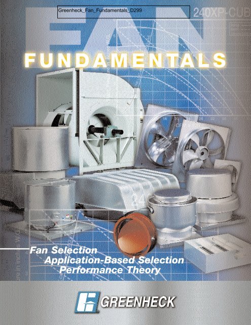
Fan Selection<br />
Application-Based Selection<br />
Performance Theory
SELECTING THE RIGHT FAN FOR THE JOB<br />
This book is designed to help you select the fan that will best<br />
fit the application for which it is intended. With the large<br />
number of different fan types and sizes available it's<br />
necessary to know which fan model does the best job in<br />
certain applications and then to be able to select the most<br />
economical fan size for the job.<br />
With that in mind, this guide is constructed in three sections.<br />
Section One describes how to select a fan using catalog<br />
performance tables with a given air volume and static<br />
pressure. This section also interprets Greenheck model<br />
numbers and illustrates the relationship between fan speed<br />
and airflow.<br />
Section Two covers the basics of fan selection—determining<br />
the proper fan model, air volume, static pressure and<br />
loudness appropriate for a given application. This is<br />
important when your customer does not know the amount of<br />
air to be moved or the resistance to airflow that will be<br />
encountered. This section also illustrates proper fan<br />
installation and proper wheel rotation.<br />
Section Three goes beyond fan selection with information<br />
of a more comprehensive and technical nature about air<br />
movement and air systems.
TABLE OF CONTENTS<br />
SECTION 1<br />
INTRODUCTION TO FAN SELECTION<br />
Terms .............................................................. 4<br />
Model Designation .......................................... 4<br />
Reading Performance Charts .......................... 5<br />
Matching a Specification ............................... 7<br />
Cross Reference Chart .................................. 8<br />
SECTION 2<br />
FAN SELECTION BASED ON FAN APPLICATION<br />
Fan Model ....................................................... 9<br />
Determining cfm ............................................ 16<br />
Determining Static Pressure ........................... 17<br />
Sound Levels .................................................. 19<br />
Motor Horsepower ......................................... 19<br />
Installation ...................................................... 20<br />
Wheel Rotation ............................................... 20<br />
SECTION 3<br />
FAN PERFORMANCE<br />
Fan Dynamics ................................................. 21<br />
System Dynamics .......................................... 21<br />
Combining Fan and System Dynamics .......... 22<br />
Adjusting Fan Performance ............................ 23<br />
Fan Laws ........................................................ 24
This is the first and most basic of this manual’s three<br />
sections, all of which are designed to enable you to<br />
select the right fan for the job. Look at this first section<br />
as a “user’s manual” for Greenheck literature. It will<br />
answer the following questions (and more): What is a<br />
SONE? How are model numbers and performance<br />
tables used to select a fan? How are direct drive and<br />
Terms<br />
Model Designation<br />
For Greenheck belt drive models, the model<br />
designation tells the model type, size and the motor hp.<br />
EXAMPLE: GB-90-4<br />
Model is GB hp is 1/4<br />
Nominal Wheel Dia. 9"<br />
For direct drive units, the model designation tells the<br />
model type, the size and the motor/fan rpm.<br />
EXAMPLE: G-120-B<br />
4<br />
INTRODUCTION TO FAN SELECTION<br />
Model is G rpm is 1140<br />
Nominal Wheel Dia. 12"<br />
belt driven fans different? What types of motors and<br />
accessories are used with these fans? Are there<br />
Greenheck fans that will match the size and<br />
performance of fans from other manufacturers? The<br />
goal is to understand and use the Greenheck literature<br />
as an important tool in filling a customer’s fan order.<br />
cfm - Cubic Feet Per Minute. A measure of airflow<br />
Ps - Static Pressure. Resistance to airflow measured in inches of water gauge.<br />
sone - A measure of loudness. One sone can be approximated as the loudness of a quiet<br />
refrigerator at a distance of 5 feet. Sones follow a linear scale, that is, 10 sones are<br />
twice as loud as 5 sones.<br />
Bhp- Brake Horsepower. A measure of power consumption. Used to determine the proper<br />
motor horsepower and wiring.<br />
hp- Horsepower. Used to indicate a fan’s motor size.<br />
rpm - Revolutions Per Minute. Measure of fan speed.<br />
TS - Tip Speed. The speed of the tip of a fan wheel or prop measured in feet per minute.<br />
AMCA - Air Movement and Control Association. A nationally recognized association which<br />
establishes standards for fan testing and performance ratings. AMCA also licenses air<br />
volume and sound certified ratings.<br />
The table below lists model designation suffixes for<br />
motor horsepower and fan rpm.<br />
Belt Drive Direct Drive<br />
Suffix Motor hp Suffix Fan rpm<br />
4 1/4 A 1725<br />
3 1/3 B 1140<br />
5 1/2 C 860<br />
7 3/4 D 1550<br />
10 1 G 1300<br />
15 1 1/2 E 1050<br />
20 2<br />
30 3<br />
50 5<br />
75 7 1/2
The most important part of selecting a fan is the ability<br />
to read the performance charts. Most of the<br />
performance charts in the catalog are similar and are<br />
read in the same manner. Models RSF and BCF are<br />
Assume that a job requires a belt drive roof exhauster<br />
to move 1000 cfm against 0.25" Ps. Refer to the<br />
performance model at the bottom of this page. Start at<br />
the top of the chart with the 0.25" Ps column. (All<br />
numbers in this column correspond to .25" Ps.) Now<br />
follow the column downward until a value is found that<br />
slightly exceeds 1000 cfm. In this case, 1012 cfm is the<br />
first box that meets the requirements.<br />
Note: Notice that each performance box is divided into<br />
3 smaller boxes. The numbers refer to cfm, Sones and<br />
Bhp.<br />
Example:<br />
cfm<br />
Sones Bhp<br />
At this performance point, the sone value is 11.1 and<br />
the fan Bhp required is 0.16. Now by following the row<br />
to the left, we can determine fan rpm and fan model. In<br />
this case, the fan rpm is 1510 and the model is GB-90-<br />
4 which has a 1/4 hp motor.<br />
Notice that the GB-90-4 is not the only model to<br />
choose from. If we follow the 0.250" Ps column down<br />
further, we find a performance point at 1010 cfm. At<br />
Table 2<br />
MODEL<br />
(rpm RANGE)<br />
GB-90-4<br />
(1290-1710)<br />
GB-100-4-2A<br />
(1020-1400)<br />
GB-100-4-3A<br />
(1260-1635)<br />
GB-100<br />
hp<br />
1/4<br />
1/4<br />
1/4<br />
1/3<br />
rpm TS<br />
1360 3983<br />
1510 4422<br />
1710 5008<br />
1070 3116<br />
1355 3946<br />
1260 3669<br />
1635 4761<br />
1800 5242<br />
Reading Performance Charts<br />
1012<br />
11.1 0.16<br />
Belt Drive Selection<br />
exceptions to this rule. The selection procedure for<br />
these models is handled separately. Direct drive and<br />
belt drive fans are also addressed separately.<br />
this point, the sone value is 7.9 and the Bhp is 0.14.<br />
Following across to the left we find the rpm to be 1355.<br />
The model is GB-100-4-2A, which also has a 1/4 hp<br />
motor.<br />
Both the GB-90-4 and the GB-100-4-2A will perform<br />
the air movement task equally as well. However, the<br />
sound generated by the fan may have to be<br />
considered. Compare the sone values: 7.9 sones for<br />
the GB-100 and 11.1 for the GB-90. The GB-100 is<br />
about 30% quieter. Where a low sound fan is required,<br />
the GB-100 would be a better selection. If loudness is<br />
not a factor, the GB-90 would be a better selection<br />
because it is less expensive.<br />
Another possibility for this particular selection is a GB-<br />
100-4-3A. Even though there is no performance box<br />
showing close to 1000 cfm, there are two performance<br />
boxes that bracket 1000 cfm. At 921 cfm the fan will be<br />
running at 1260 rpm. At 1269 cfm the fan will be<br />
running at 1635 rpm. Therefore, there is an rpm for this<br />
model that will correspond to 1000 cfm (obviously<br />
somewhere within the 1260-1635 rpm range). As with<br />
all Greenheck belt drive fans, intermediate cfm values<br />
are easily achieved by adjusting the motor pulley (see<br />
illustration on next page).<br />
STATIC PRESSURE / CAPACITY<br />
0.000 0.125 0.250 0.375 0.500 0.625 0.750 0.875 1.000<br />
Sone Bhp Sone Bhp Sone Bhp Sone Bhp Sone Bhp Sone Bhp Sone Bhp Sone Bhp Sone Bhp<br />
1030 957 884 807 725 632<br />
10.1 0.11 9.9 0.12 9.6 0.12 9.3 0.12 8.8 0.13 8.5 0.13<br />
1144 1078 1012 946 875 800 720 607<br />
11.4 0.15 11.2 0.16 11.1 0.16 10.7 0.17 10.4 0.17 10.0 0.17 9.8 0.17 9.5 0.17<br />
1295 1237 1179 1121 1061 999 934 866 785<br />
13.4 0.22 13.3 0.23 13.2 0.23 13.0 0.24 12.7 0.24 12.4 0.25 12.1 0.25 11.8 0.25 11.6 0.25<br />
906 818 731 607<br />
6.0 0.060 5.4 0.065 5.0 0.070 4.3 0.070<br />
1148 1077 1010 943 856 739<br />
8.5 0.12 8.1 0.13 7.9 0.14 7.8 0.14 7.2 0.14 6.8 0.14<br />
1067 991 921 840 735 385<br />
7.6 0.099 7.1 0.104 6.8 0.112 6.5 0.115 5.9 0.115 4.4 0.083<br />
1385 1325 1269 1214 1161 1094 1019 928 792<br />
11.1 0.22 10.8 0.22 10.4 0.23 10.2 0.24 9.8 0.25 9.3 0.25 8.9 0.25 8.4 0.25 7.8 0.24<br />
1525 1471 1418 1367 1320 1270 1208 1141 1064<br />
13.2 0.29 12.8 0.30 12.5 0.30 12.3 0.31 12.2 0.33 11.3 0.33 10.8 0.33 10.6 0.33 10.1 0.33<br />
5
One advantage of choosing the GB-100-4-3A over the<br />
GB-100-4-2A is that it is capable of running at higher<br />
rpm’s, which enables the fan to move more air if<br />
necessary.<br />
Motor pulleys are adjusted by loosening the set screw<br />
and turning the top half of the pulley (see illustrations at<br />
right). This causes the pulley diameter to change, which<br />
results in changing the fan rpm.<br />
Direct Drive Selection<br />
Selection of direct drive fans (those with the motor<br />
shaft connected to the fan wheel or propeller) is nearly<br />
the same as belt drive selection. However, there are<br />
two differences worth noting. Where belt drive fan<br />
speed can be altered by adjusting the motor pulley,<br />
direct drive fans (since they have no pulleys) must use<br />
a different method.<br />
1. To adjust a direct drive fan's speed (also motor<br />
speed) or to provide a means of meeting an exact<br />
performance requirement, a speed control can be<br />
furnished (except on 1725 rpm motors). Speed controls<br />
vary the voltage supplied to the fan and slows it down;<br />
a principle similar to the way dimmer light switches<br />
work.<br />
Motor Information (Belt Drive Only)<br />
When specifying a belt drive fan, the model<br />
designation does not completely describe the unit.<br />
Additional information about the motor is necessary.<br />
These items are listed below:<br />
Motor Enclosure<br />
This will be either “Open” (open, drip proof), “TE”<br />
(totally enclosed) or “EXP” (explosion resistant). Open<br />
is the most common and will be supplied unless<br />
otherwise specified.<br />
Model Common Accessories<br />
G & GB<br />
CUBE<br />
SB<br />
Roof Curb<br />
Backdraft Damper<br />
Roof Curb<br />
Grease Container<br />
Wall Mount Housing or<br />
Wall Mount Collar<br />
2. Models C, CW and SQ have sizes 60-95 that are<br />
provided with 3 speed motors. The three speeds are<br />
1550 rpm (D), 1300 rpm (G) and 1050 rpm (E). Changing<br />
a motor lead is all that is necessary to change speeds.<br />
When selecting a model with 3 speed motors, it is<br />
recommended that the G speed be chosen whenever<br />
possible. This is the middle speed, which gives the<br />
greatest flexibility in air volume because airflow can be<br />
increased or decreased simply by changing a motor<br />
lead.<br />
Typical Motor Tag<br />
Electrical Instructions<br />
Suffix Letter Motor Speed Wiring Connections<br />
D 1550 rpm White to L1 Black to L2<br />
G 1300 rpm White to L1 Blue to L2<br />
E 1050 rpm White to L1 Red to L2<br />
Speeds<br />
Motors are available in either single speed or two<br />
speed. Single speed motors are 1725 rpm. Two speed<br />
motors will be 1725/1140 rpm. Single speed will be<br />
supplied unless otherwise specified.<br />
Electrical Characteristics<br />
Voltage and phase. Voltage can be 115, 208, 230 or<br />
460. Phase is either single or 3 phase. A 115 volt,<br />
single phase motor is shown as 115/1. Typically,<br />
motors of 1/2 hp and less are single phase. Motors of<br />
3/4 hp and greater are 3 phase.<br />
Accessories<br />
Most fans are ordered with accessories. Here are some common accessories for selected models:<br />
6<br />
Model Common Accessories<br />
SP & CSP<br />
SQ & BSQ<br />
Opening the pulley decreases fan rpm.<br />
Closing the pulley increases fan rpm.<br />
Speed Control<br />
Discharge Vents<br />
Backdraft Damper<br />
Vibration Isolators<br />
Belt
Matching a Specification<br />
There will be times when a Greenheck model will have<br />
to be matched to a competing manufacturer’s unit. To<br />
aid in these circumstances, we have provided a cross<br />
reference chart which includes our nine most common<br />
competitors. If the manufacturer you need is not on this<br />
chart, contact Greenheck for assistance.<br />
To use the cross reference chart, on next page, start<br />
with the manufacturer at the top. Then follow down<br />
until the model in question is found. Follow across to<br />
Model RSF and BCF Selection<br />
The RSF and BCF selection charts are different from all<br />
other selection charts. For these models, the cfm<br />
values are at the left side of the chart in a single column<br />
and the rpms are in the performance boxes. It is just the<br />
opposite for other models. The reason for this is that<br />
the RSF and BCF models are forward curved, and the<br />
fan industry historically catalogs forward curved fans in<br />
this fashion.<br />
Sample problem:<br />
Choose the fan size and appropriate motor horsepower<br />
to move 980 cfm against 0.625" Ps.<br />
Solution: (Refer to table below)<br />
The first row in the chart corresponds to 980 cfm.<br />
Follow across to the right to the 0.625" Ps column. The<br />
performance box reveals that size 90 will meet this<br />
performance at 893 rpm and will require 0.20 Bhp.<br />
Motor hp selection for forward curved fans is more<br />
MODEL<br />
RSF-90<br />
RSF-100<br />
cfm OV<br />
980 1065<br />
1200 1304<br />
1420 1543<br />
1640 1783<br />
1860 2022<br />
2080 2261<br />
1240 1097<br />
1780 1575<br />
2140 1894<br />
rpm<br />
Bhp<br />
rpm<br />
Bhp<br />
rpm<br />
Bhp<br />
rpm<br />
Bhp<br />
rpm<br />
Bhp<br />
rpm<br />
Bhp<br />
rpm<br />
Bhp<br />
rpm<br />
Bhp<br />
rpm<br />
Bhp<br />
the left to determine which Greenheck model is<br />
equivalent. Once this is determined, refer to the<br />
Greenheck catalog to find the best size to meet the<br />
specified performance.<br />
Hint: Typically, when matching a Greenheck fan to a<br />
competitive model, the size should also be matched. If<br />
you are unsure of the size of the competitive unit,<br />
compare fan rpm. Fans of equal size should move<br />
approximately the same amount of air.<br />
complicated. The Bhp is only 0.20, which suggests that<br />
a 1/4 hp motor is adequate. However, forward curved<br />
fans draw more horsepower at low Ps than at high Ps.<br />
Assume this fan was running at about 893 rpm, but<br />
instead of 0.625" Ps, it was operating at only 0.25" Ps.<br />
The new performance box in the 0.25" Ps column<br />
reveals 894 rpm at 0.45 Bhp. The airflow would then be<br />
1860 cfm.<br />
Notice that as the Ps was reduced from 0.625" to 0.25",<br />
the Bhp increased from 0.20 to 0.45. This would burn<br />
out the 1/4 hp motor quickly. With this in mind, it is<br />
good practice to size RSF and BCF motors at least one<br />
size larger than necessary based on the Bhp value in<br />
the performance box, especially if the estimated Ps is<br />
questionable.<br />
For this case, an RSF-90-3 (1/3 hp motor) would be a<br />
good selection if we had confidence in the estimated<br />
Ps. Otherwise, use an RSF-90-5 (1/2 hp motor).<br />
RSF-90-4 (1/4 hp motor) is not recommended for this<br />
job.<br />
STATIC PRESSURE / CAPACITY<br />
0.125 0.250 0.375 0.500 0.625 0.750 1.000 1.250 1.500 1.750<br />
521 630 725 812 893 967<br />
0.08 0.11 0.13 0.16 0.20 0.23<br />
593 685 771 849 925 994 1125<br />
0.13 0.16 0.19 0.23 0.26 0.30 0.38<br />
668 747 825 898 966 1031 1153 1267 1371<br />
0.19 0.23 0.27 0.31 0.35 0.39 0.48 0.57 0.67<br />
746 819 887 953 1016 1077 1191 1298<br />
0.28 0.33 0.37 0.42 0.46 0.51 0.61 0.71<br />
828 894 954 1014 1073 1128 1236<br />
0.40 0.45 0.50 0.55 0.60 0.65 0.76<br />
910 970 1027 1080 1134<br />
0.54 0.60 0.66 0.71 0.77<br />
476 572 656 733 807 876<br />
0.10 0.13 0.16 0.19 0.23 0.27<br />
605 679 748 813 873 931 1040 1143 1240<br />
0.24 0.29 0.33 0.38 0.42 0.47 0.56 0.66 0.77<br />
699 763 823 880 935 989 1086 1181 1269 1354<br />
0.40 0.45 0.50 0.56 0.61 0.67 0.78 0.89 1.00 1.12<br />
7
Cross Reference Chart<br />
Greenheck Cook Penn Acme Jenn Carnes ILG (COOLAIR) Chelsea Dayton<br />
G ACE-D Domex DX PRN CRD VEDK CRF RDD 3C(401, 424,425)<br />
CE, CX, CH C-D, CVD, TCD XQ, XR, AT, AW VEDB, VEDC 3C506<br />
GB ACE-B Domex DXB PN,PNN NBCR VEBK CRB RDB 7H8 (14-57), 7C8(58,60-62)<br />
CDE, CBX C-B, TCB, UCB KB,JB,MB, BCR VEBC LSB 7C4(82,84,86,98)<br />
AB, LB<br />
CUE ACRU-D Fumex FX PDU N/A VUDK CUD N/A 3C(367,766-770)<br />
4C(398-400,836,837)<br />
CUBE ACRU-B,VCR Fumex FXB PNU NBTD VUBK, VRBK UBC,CUB CUBA 7H(894-928); 3C5(01-03)<br />
UCBE,UCBH URB, R-B,BTD FMXB PUB, PU, PUH NBRTD VUBB, URBA CVB 3C549<br />
CW ACW-D Fumex WFX PDU-W CWD VWDK CWD WDC 4C(398-400,836,837)<br />
SW, GW CW Domex WX, PW VWDB CWF 3C367,4C(553-719)<br />
WA, WB 5C5(14-15)<br />
CWB ACW-B Fumex WFXB PNU-W NBTD VWBK CWB WBC 7H(894-923)<br />
GWB CWB, TWB Domex WCB,WLB PWB NBRTD(UL 762) VWBB<br />
SP Gemini GC Zephyr V J, EC, L VCDB QA, CCV CF 4C(714,833)<br />
Z, (RA,TD) 2D0(64,65,67,68,70-76,82)<br />
CSP Gemini Inline Zephyr V N/A VCDB CCH DCF 4C756,3C505<br />
GN Z, (TDA)<br />
BCF DBX,TDB ZC, ZCC DM N/A VDBA N/A BCF,TCF N/A<br />
SQ SQI-D, SQN-D Centrex SX XD ISD VIDK SQRD,SQLD N/A N/A<br />
DSQ,SQD CV-D ILD VIDB, AMDA CLD<br />
BSQ SQI-D,SQN-B Centrex XB ILB VIBK SQLB,SQMB SBCL N/A<br />
SX-BC VIBA<br />
SE SWD P FQ GDW LYDA,LZDA CDC,UD WFA 4C3(61-64),4C0(07,09,10)<br />
SDE SD HDW,FDW LWDA PV BBX<br />
SBE/SBS XLW,XMW BBK,BFL DC TBW LWBA,LMBA CBL,CBH FHA,IND 7CC(73-99),7CF(01-45)<br />
SPFE/SPFS SWB,SPB TYPE T PF 7CC(01-72)<br />
SBE/SBS-3 HWB BF DCH LBW LABA,LCBA CBHX N/A 7CC(73-99), 7CF(01-45)<br />
SPNE/SPNS XLWH,XMWH LBWA 7CC(01-72)<br />
SBCE/SBCS AWB BC,BAT DCK, K HBW LRBA,LNBA CBC IND 7CK(38-52)<br />
RBE/RBS HSE/HSS AC EC/EC-S HBR LTBA,LGBA PB N/A 7CF(46-99), 7CH(03-17)<br />
RPE,RPS 7CH(18-89)<br />
RBU LSU HF,HZ UBG,UB N/A LUBA JB RUBA 7C8(63-87,97), 7C9(03-08)<br />
PBU,PBU AVB, VB<br />
RSF ASP Muffan MU AFS BCFS VSBB M-PBS BAS 7C1(58-61,64-69,76-81),<br />
CFS PLS VSBA 7C2 (06,08,13,18,20,23,25,55)<br />
7C3(48,50,54,56,58,61,65-68)<br />
7C3(70-78,92-95)<br />
FHI/FHR VR/VI GRV-1 EV/IV RVA/RVG GI/GE TEV/TIV RR-L N/A<br />
GRS PR, TR DR LQV GRV GS,GSAA ARVE RDV N/A<br />
SWB CPV,CPS Dynamo D,QX QBR<br />
GWB<br />
JVS VBBA BCL UXB 7H1(23-95)<br />
Competitor Model Number Deciphering Hints<br />
8<br />
Cook-<br />
Direct Drive<br />
120 W 10 D Direct Drive<br />
rpm x 100<br />
Model ACW<br />
Wheel Size<br />
Letter Designations<br />
C=ACE (G,GB)<br />
R=ACRU (CUBE)<br />
W=ACW (CW,CWB)<br />
V=VCR (CUBE)<br />
Belt Drive<br />
150 V 6 B Belt Drive<br />
3/4 hp<br />
Model VCR<br />
Wheel Size = 15"<br />
Horsepower Designations<br />
2=1/6 hp<br />
3=1/4<br />
4=1/3<br />
5=1/2<br />
6=3/4<br />
7=1<br />
8=1 1/2<br />
9=2<br />
10=3<br />
11=5<br />
12=7 1 /2<br />
Acme -<br />
Direct Drive<br />
PW 135 A 8 860 rpm<br />
1/20 hp<br />
Wheel Size =13.5"<br />
Model PW<br />
Direct Drive rpm Designation<br />
8 = 860 rpm<br />
6 = 1160 rpm<br />
4 = 1725 rpm<br />
Belt Drive<br />
PNN 163 G<br />
1/2 hp<br />
Wheel Size = 16.3"<br />
Model PNN<br />
Horsepower Designation<br />
A=1/20 hp<br />
B=1/12<br />
C=1/8<br />
D=1/6<br />
E=1/4<br />
F=1/3<br />
G=1/2<br />
H=3/4<br />
J= 1<br />
K=1 1/2<br />
L=2<br />
M=3<br />
N=5<br />
P=7 1/2<br />
R=10
FAN SELECTION BASED ON FAN APPLICATION<br />
Basic Overview<br />
Ventilating a building simply replaces stale or foul air<br />
with clean, fresh air. Although the ventilation process is<br />
required for many different applications, the airflow<br />
fundamentals never change:<br />
Undesired air out, fresh air in<br />
The key variables that do change depending on<br />
applications are the fan model and the air volume flow<br />
rate (cfm). Other considerations include the resistance<br />
to airflow (static pressure or Ps) and sound produced<br />
by the fan (Sones).<br />
Occasionally, a customer will require a fan to perform a<br />
particular function, yet does not know which model to<br />
use or even what cfm is necessary. In this case, some<br />
fan specification work must be done.<br />
Fan Model<br />
Fans all perform the basic function of moving air from<br />
one space to another. But the great diversity of fan<br />
applications creates the need for manufacturers to<br />
develop many different models. Each model has<br />
benefits for certain applications, providing the most<br />
economical means of performing the air movement<br />
function. The trick for most users is sorting through all<br />
of the models available to find one that is suitable for<br />
their needs. Here are some guidelines.<br />
Direct Drive vs Belt Drive<br />
Direct drive fans are economical for low volume (2000<br />
cfm or less) and low static pressure (0.50" or less). They<br />
require little maintenance and most direct drive motors<br />
can be used with a speed control to adjust the cfm.<br />
Belt drive fans are better suited for air volumes above<br />
2000 cfm or static pressures above 0.50". Adjustable<br />
pulleys allow fan speed and cfm to be adjusted by<br />
about 25%. High temperature fans (above 120°F) are<br />
almost always belt driven.<br />
Fan specification is usually not a precise science and<br />
can be done confidently when the fan application is<br />
understood.<br />
Based on the application, four parameters need to be<br />
determined. They are:<br />
1. Fan Model<br />
2. cfm<br />
3. Static Pressure (Ps)<br />
4. Loudness limit (Sones)<br />
The information that follows will help walk you through<br />
this type of problem and enable you to select the right<br />
fan for the job.<br />
Propeller vs. Centrifugal Wheel<br />
Propeller fans provide an economical method to move<br />
large air volumes (5,000+ cfm) at low static pressures<br />
(0.50" or less). Motors are typically mounted in the<br />
airstream which limits applications to relatively clean<br />
air at maximum temperatures of 110°F.<br />
Centrifugal fans are more efficient at higher static<br />
pressures and are quieter than propeller fans. Many<br />
centrifugal fan models are designed with motors<br />
mounted out of the airstream to ventilate contaminated<br />
and high temperature air.<br />
Fan Location<br />
Fan models are designed to be mounted in three<br />
common locations: on a roof, in a wall, or in a duct.<br />
Whatever the location, the basic fan components do<br />
not change. Only the fan housing changes to make<br />
installation as easy as possible.<br />
Determining the best location for a fan depends on the<br />
airflow pattern desired and the physical characteristics<br />
of the building. By surveying the building structure and<br />
visualizing how the air should flow, the place to locate<br />
the fan usually becomes evident.<br />
Examples of fans installed in common applications are<br />
illustrated on the following 6 pages. Even if you come<br />
across an application that is not shown in this manual,<br />
the concepts remain the same.<br />
9
Recommended Exhaust Fans<br />
<strong>Commercial</strong> <strong>Kitchen</strong> <strong>Ventilation</strong><br />
Model CUBE Model CWB Model SWB<br />
Belt Drive Upblast Roof Exhaust Belt Drive Sidewall Exhaust Belt Drive Utility Blower<br />
600-30,000 cfm 300-12,500 cfm 1,000-30,000 cfm<br />
Up to 5.0" wg Up to 2.5" wg Up to 4.0" wg<br />
The above models are designed for exhausting dirty or grease laden air up and away from the roof line or away<br />
from the wall in commercial restaurant applications. All three models are UL 762 listed for restaurant applications<br />
and for operation with air temperatures up to 300°F.<br />
Recommended Supply Fans<br />
Model RSF<br />
Filtered Roof Supply<br />
900-14,300 cfm<br />
Up to 1.5" wg<br />
Model KSU<br />
Tempered Roof Supply<br />
1,000-7,400 cfm<br />
Up to 2.0" wg<br />
Model BSQ<br />
Belt Drive Inline Fan<br />
300-26,600 cfm<br />
Up to 3.5" wg<br />
The above models are designed to provide efficient economical make-up air to replenish the air exhausted<br />
through the kitchen hood. Provisions for make-up air must be considered for proper kitchen ventilation.<br />
10
<strong>Commercial</strong> <strong>Kitchen</strong> <strong>Ventilation</strong><br />
Fan Sizing<br />
Sidewall Exhaust<br />
Fan<br />
Model GWB<br />
This drawing shows a commercial kitchen with a typical<br />
kitchen ventilation system consisting of a roof mounted<br />
CUBE upblast exhaust fan and a Model RSF supply fan.<br />
Exhaust fan variations include the model CWB sidewall<br />
exhaust fan (also shown) when penetrating the roof is not<br />
practical. The Model SWB utility blower is recommended<br />
when higher static pressure capability is Exhaust required Only to pull<br />
Hood<br />
exhaust through long duct runs (typically Model 3 GHW stories or<br />
more).<br />
Model RSF<br />
Supply Fan<br />
Outside Supply Air<br />
Replacing Exhausted Air<br />
Exhaust<br />
When not specified by local codes, the following guidelines may be used<br />
to determine the minimum kitchen hood exhaust cfm. Some local codes<br />
require 100 cfm/Ft. 2 of hood area for wall style hoods.<br />
Supply<br />
Recommended supply airflow is 90% of<br />
exhaust cfm. The remaining 10% of<br />
supply air will be drawn from areas<br />
adjacent to the kitchen, which helps<br />
prevent undesirable kitchen odors from<br />
drifting into areas such as the dining<br />
room.<br />
NFPA Considerations<br />
The National Fire Protection Association specifies<br />
minimum distance criteria for restaurant exhaust and<br />
supply fans as shown below:<br />
Arrangement A<br />
1. Roof deck to top of exhaust fan windband - 40" min.<br />
2. Roof deck to top of curb - 18" min.<br />
3. Supply fan intake - 10' min. from all exhaust fans.<br />
(Optional) Arrangement F<br />
For applications where the 10' horizontal distance<br />
cannot be met, vertical separation between exhaust and<br />
supply must be at least 3 feet.<br />
Upblast Exhaust Fan<br />
Model CUBE<br />
Vented Curb<br />
Model GPFV<br />
Model GHW<br />
Exhaust Hood<br />
Cooking<br />
Equipment<br />
Sidewall Exhaust<br />
Fan Option<br />
Model CWB<br />
Type of Cooking Equipment cfm/Ft. 2 of Hood<br />
Light Duty Oven, Range, Kettle 50<br />
Medium Duty Fryer, Griddle 75<br />
Heavy Duty Charbroiler, Electric Broiler 100<br />
Static pressure typically ranges from .625" to 1.0" for 1 story buildings.<br />
40" Min.<br />
18" Min.<br />
KSU Arrangement A<br />
10'-0" Min.<br />
KSU Arrangement F (optional)<br />
37"<br />
12"<br />
11
12<br />
General <strong>Commercial</strong> <strong>Ventilation</strong><br />
G<br />
Direct Drive Roof Exhaust<br />
80-4300 cfm<br />
Up to .75" wg<br />
GB<br />
Belt Drive Roof Exhaust<br />
200-37,000 cfm<br />
Up to 2.5" wg<br />
CW<br />
Direct Drive Wall Exhaust<br />
80-3,300 cfm<br />
Up to .625" wg<br />
CWB<br />
Belt Drive Wall Exhaust<br />
300-12,500 cfm<br />
Up to 2.5" wg<br />
The above models are designed for exhausting relatively clean air at temperatures up to 130°F. Motors<br />
are out of the airstream. Direct drive sizes 60-95 are equipped with 3-speed motors for maximum airflow<br />
flexibility. All direct drive units except 1725 rpm (A speed) can be used with a speed control.<br />
SP<br />
Ceiling Exhaust<br />
50-1,600 cfm<br />
Up to 0.75" wg<br />
CSP<br />
Inline Cabinet Fan<br />
100-3,800 cfm<br />
Up to 1.0" wg<br />
Models SP and CSP are designed for exhausting relatively<br />
clean air at temperatures up to 110°F. Motors are in the<br />
airstream. All models are direct drive and can be used with<br />
a speed control.<br />
BSQ<br />
Belt Drive Inline Fan<br />
300-26,600 cfm<br />
Up to 3.0" wg<br />
SQ<br />
Direct Drive Inline Fan<br />
200-5,000 cfm<br />
Up to 1.0" wg<br />
Models SQ and BSQ are versatile<br />
fans that can be used for exhaust<br />
or supply and can be mounted in<br />
any position. Two removable side<br />
panels provide access for service.
Typical <strong>Commercial</strong> <strong>Ventilation</strong> Installations<br />
Sound Critical Room<br />
(Office, Conference<br />
Room, etc.)<br />
Model G or GB*<br />
Roof Exhauster<br />
Office Office<br />
This drawing demonstrates how to ventilate<br />
more than one area with a single fan.<br />
Model GRS<br />
Domed Gravity Hood<br />
Model CSP, SQ or BSQ*<br />
Inline Cabinet Fan<br />
Insulated Ductwork<br />
Hall<br />
For ultra-quiet applications, insulate ductwork<br />
and mount fan over a less sound critical area.<br />
*Illustrations show fan types typically used in these<br />
applications. The specific fan model required depends on<br />
the conditions of each individual application.<br />
Exhaust through wall or roof<br />
Greenheck Accessory<br />
Hooded Wall Vent<br />
Multi-story building<br />
prevents roof penetration<br />
Ceiling/Floor<br />
Model CW or CWB*<br />
Sidewall Exhaust Fan<br />
Engine Room,<br />
Laundry Room, etc.<br />
Greenheck<br />
Accessory Roof Vent<br />
Model SP<br />
Ceiling Exhaust Fan<br />
Rest Room<br />
Typical restroom exhaust system.<br />
Exhausting through an outside wall is<br />
often the best solution when<br />
penetrating the roof is not practical.<br />
13
RBU<br />
Model SB<br />
Belt Drive<br />
Propeller Sidewall<br />
2,000-85,000 cfm<br />
Model RBU<br />
Belt Drive<br />
Propeller Upblast<br />
4,000-62,000 cfm<br />
Model RB<br />
RBS-Supply<br />
RBE-Exhaust<br />
RBF-Filtered<br />
Belt Drive Propeller Roof<br />
2,000-82,000 cfm<br />
General Industrial <strong>Ventilation</strong><br />
Outside air<br />
drawn in by<br />
fan<br />
Model RBU<br />
roof upblast fan<br />
Model RBS<br />
roof supply<br />
fan<br />
Intake<br />
Louvers<br />
Outside air<br />
replacing air being<br />
exhausted<br />
Loading<br />
dock Doors<br />
Outside air<br />
entering<br />
through door<br />
opening<br />
Loading<br />
dock Doors<br />
Typical Applications<br />
Propeller fans are ideal for ventilating high air volumes at low static pressures (0.50" or less). Industrial<br />
applications often include factories and warehouses. A variety of fan models offer flexibility for roof or wall mount<br />
as well as exhaust or supply. However, because the motors are mounted in the airstream, these models are not<br />
recommended for temperatures above 110°F.<br />
14<br />
RBUMO<br />
Internal air<br />
exiting<br />
through door<br />
opening
Model SWB<br />
Belt Drive Utility Blower<br />
1,000-30,000 cfm<br />
Temperatures up to 300°F<br />
Up to 4.0" wg<br />
Model BSQ<br />
Belt Drive Inline Fan<br />
300-26,600 cfm<br />
Temperatures up to 180°F<br />
Up to 3.5" wg<br />
High Static Pressure <strong>Ventilation</strong><br />
Model SWB<br />
utility blower<br />
Contaminated Air<br />
Office Space<br />
Work<br />
Station<br />
Exhausting Foul Air<br />
Discharge Air<br />
Duct System<br />
Work<br />
Station<br />
Supplying Fresh Air<br />
Work<br />
Station<br />
Duct System<br />
Work<br />
Station<br />
Work<br />
Station<br />
Intake Louvers<br />
Outside air<br />
replacing air<br />
being<br />
exhausted<br />
Model BSQ<br />
square inline fan<br />
built into duct system<br />
Typical Applications<br />
Models SWB and BSQ are general, all-purpose fans that are capable of moving high air volumes<br />
against high static pressures (up to 4.0" wg). High static pressures are generated by long or complex<br />
duct systems, especially when capture hoods are present. Both models can be used for either exhaust<br />
or supply. Model SWB is designed to be mounted indoors or outdoors, while model BSQ can be used<br />
indoors only.<br />
Weatherhood<br />
Outside Air<br />
Stale air exiting<br />
through exhaust<br />
louver<br />
15
Determining cfm<br />
After the model is known, the cfm must be determined.<br />
Consult local code requirements or the table below for<br />
suggested air changes for proper ventilation.<br />
The ranges specified will adequately ventilate the<br />
corresponding areas in most cases. However, extreme<br />
conditions may require “Minutes per Change” outside<br />
of the specified range. To determine the actual number<br />
needed within a range, consider the geographic<br />
location and average duty level of the area. For hot<br />
Area Min./Chg. Area Min./Chg. Area Min./Chg.<br />
Assembly Hall 3-10 Dance Hall 3-7 Machine Shop 3-6<br />
Attic 2-4 Dining Room 4-8 Mill 3-8<br />
Auditorium 3-10 Dry Cleaner 2-5 Office 2-8<br />
Bakery 2-3 Engine Room 1-3 Packing House 2-5<br />
Bar 2-4 Factory 2-7 Projection Room 1-2<br />
Barn 12-18 Foundry 1-5 Recreation Room 2-8<br />
Boiler Room 1-3 Garage 2-10 Residence 2-6<br />
Bowling Alley 3-7 Generator Room 2-5 Restaurant 5-10<br />
Cafeteria 3-5 Gymnasium 3-8 Rest Room 5-7<br />
Church 4-10 <strong>Kitchen</strong> 1-5 Store 3-7<br />
Classroom 4-6 Laboratory 2-5 Transfer Room 1-5<br />
Club Room 3-7 Laundry 2-4 Warehouse 3-10<br />
Sample problem:<br />
A building requires an exhaust fan to ventilate a general<br />
office (see diagram below) which measures 30' x 40' x<br />
8'. The office is often crowded.<br />
Solution:<br />
The total room volume is 30' x 40' x 8' = 9600 cubic<br />
feet. From the chart, the range for general offices is 2-8<br />
minutes per change. Since the office has heavier than<br />
normal usage, 4 minutes per change is recommended.<br />
Therefore, the required exhaust is:<br />
16<br />
Exhaust fan to be sized<br />
8'<br />
40'<br />
climates and heavier than normal area usage, select a<br />
lower number in the range to change the air more<br />
quickly. For moderate climates with lighter usages,<br />
select a higher number in the range.<br />
To determine the cfm required to adequately ventilate<br />
an area, divide the room volume by the appropriate<br />
“Minutes per Change” value.<br />
Suggested Air Changes for Proper <strong>Ventilation</strong><br />
Room Volume<br />
cfm = Room Volume = L x W x H (of room)<br />
Min./Chg.<br />
9600 ft3 = 2400 cfm<br />
4 min.<br />
Since the air to be exhausted is relatively clean, this is<br />
an ideal application for a model GB fan.<br />
Note: In this example, make-up air was provided<br />
through a set of louvers at the wall farthest from the<br />
exhaust fan. If there were no provisions for make-up air<br />
in this room, a supply fan would also have to be sized.<br />
The supply cfm should equal the exhaust cfm. Supply<br />
fan location should be as far as possible from the<br />
exhaust fan.<br />
30'<br />
Louvers to supply<br />
Makeup air
Determining Static Pressure<br />
The pressures generated by fans in ductwork are very small.<br />
Yet, accurately estimating the static pressure is critical to<br />
proper fan selection.<br />
Fan static pressure is measured in inches of water gauge.<br />
One pound per square inch is equivalent to 27.7" of water<br />
gauge. Static pressures in fan systems are typically less<br />
than 2" of water gauge, or 0.072 Psi. The drawing to the<br />
right illustrates how static pressures are measured in<br />
ductwork with a manometer.<br />
A pressure differential between the duct and the atmosphere<br />
will cause the water level in the manometer legs to rest at<br />
different levels. This difference is the static pressure<br />
measured in inches of water gauge.<br />
In the case of the exhaust fan at right, the air is being drawn<br />
upward through the ductwork because the fan is producing<br />
a low pressure region at the top of the duct. This is the same<br />
principle that enables beverages to be sipped through a straw.<br />
The amount of static pressure that the fan must overcome depends on the air velocity in the ductwork, the number<br />
of duct turns (and other resistive elements), and the duct length. For properly designed systems with sufficient<br />
make-up air, the guide lines in the table below can be used for estimating static pressure:<br />
STATIC PRESSURE GUIDELINES<br />
Non-Ducted: 0.05" to 0.20"<br />
Ducted: 0.2" to 0.40" per<br />
100 feet of duct (assuming duct<br />
air velocity falls within 1000-1800<br />
feet per minute)<br />
Fittings: 0.08" per fitting<br />
(elbow, register, grill, damper, etc.)<br />
<strong>Kitchen</strong> Hood Exh.: 0.625" to 1.50"<br />
Important: Static pressure requirements are significantly affected<br />
by the amount of make-up air supplied to an area. Insufficient<br />
make-up air will increase static pressure and reduce the amount<br />
of air that will be exhausted. Remember, for each cubic foot of air<br />
exhausted, one cubic foot of air must be supplied.<br />
To calculate the system losses, one must know the<br />
ductwork system configuration (see Ductwork figure).<br />
This duct is sized for air velocities of 1400 feet per<br />
minute. Referring to the static pressure chart, that will<br />
result in about 0.3" per 100 feet. Since we have 10 feet<br />
of total ductwork, our pressure drop due to the duct is:<br />
.3" x 10ft. = .03"<br />
100 ft.<br />
There is also a 0.08" pressure drop for each resistive<br />
element or fitting. For this example, there are 5 fittings:<br />
Duct<br />
4'<br />
Exhaust Fan<br />
Airflow<br />
Airflow out of<br />
restaurant<br />
Ductwork<br />
Grill<br />
6'<br />
1.0"<br />
Damper<br />
Atmospheric<br />
Pressure<br />
Manometer<br />
Water<br />
Airflow to<br />
exhaust fan<br />
one grill, two duct turns, one damper and louvers in<br />
the wall of the office. The total pressure drop for<br />
fittings is:<br />
5 x 0.08" = 0.4"<br />
Therefore, the total pressure drop is:<br />
0.03" + 0.40 " = 0.43"<br />
For convenience in using selection charts, round this<br />
value up to the nearest 1/8", which would be 0.50" Ps.<br />
17
Preliminary Selections<br />
At this point we know the model, cfm and Ps. With this<br />
information we can refer to the GB performance charts<br />
to determine the sizes available to move 2400 cfm<br />
against 0.50" Ps.<br />
In our case, all of the criteria can be met by more than<br />
one size of a particular model. When this occurs,<br />
choose the size that provides the greatest airflow range<br />
about the desired cfm. For example, many direct drive<br />
fans have three speeds. If possible, choose a size that<br />
uses the middle rpm. This will allow some final system<br />
adjustment if the actual cfm the job requires is<br />
somewhat higher or lower once the fan is installed. Belt<br />
driven fans have adjustable motor pulleys which allow<br />
the fan speed to be varied. With belt drive units, avoid<br />
Stability Considerations<br />
Whenever there is more than one size to choose from,<br />
it is not recommended to select from the performance<br />
box in the far right column for any given rpm unless the<br />
Ps is known to be accurate. For example, the GB- 200<br />
selection (see table below) of 2493 cfm at 0.50" Ps is<br />
the far right selection at 700 rpm3 .<br />
18<br />
MODEL<br />
(rpm RANGE)<br />
GB-140-5<br />
(1125-1360)<br />
GB-140<br />
GB-160-4<br />
(634-865)<br />
GB-160-5<br />
(852-1100)<br />
GB-180-3<br />
(618-810)<br />
GB-180-5<br />
(700-940)<br />
GB-180-7<br />
(764-1055)<br />
GB-180<br />
GB-200-5<br />
(512-770)<br />
hp<br />
1/2<br />
3/4<br />
1/4<br />
1/2<br />
1/3<br />
1/2<br />
3/4<br />
1<br />
1 1 /2<br />
2<br />
1/2<br />
rpm TS<br />
1360 5207<br />
1545 5915<br />
785 3416<br />
865 3764<br />
985 4287<br />
1100 4787<br />
770 3729<br />
810 3923<br />
900 4359<br />
940 4553<br />
1000 4843<br />
1055 5109<br />
1185 5739<br />
1335 6465<br />
1460 7071<br />
700 3917<br />
770 4308<br />
selecting near the maximum rpm of a size to allow for<br />
final adjustments if necessary.<br />
There are four GB sizes to choose from in the QD<br />
catalog. These sizes along with their performance data<br />
are in the table below.<br />
Model and Performance Box Data<br />
Size cfm Sones Bhp<br />
rpm<br />
GB-140 2556 16.8 .76 1545<br />
GB-160 2614 13.5 .53 1100<br />
GB-180 2375 8.6 .35 810<br />
GB-200 2493 7.8 .40 700<br />
The next box to the right (0.625" Ps) is empty because<br />
the performance at that point is unstable. This means<br />
that 2494 cfm at 0.50" is marginally stable.<br />
For more information on fan stability, contact<br />
Greenheck.<br />
STATIC PRESSURE / CAPACITY<br />
0.000 0.125 0.250 0.375 0.500 0.625 0.750 0.875 1.000<br />
Sone Bhp Sone Bhp Sone Bhp Sone Bhp Sone Bhp Sone Bhp Sone Bhp Sone Bhp Sone Bhp<br />
2522 2433 2346 2258 2166 2062 1942 1792 1602<br />
14.6 0.48 14.3 0.50 13.9 0.51 13.5 0.52 13.1 0.52 12.7 0.52 12.2 0.53 11.6 0.52 11.0 0.51<br />
2866 2787 2709 2634 2556 2475 2384 2286 2176<br />
17.6 0.71 18.0 0.72 17.4 0.74 17.1 0.75 16.8 0.76 15.9 0.77 14.9 0.77 14.8 0.77 14.7 0.78<br />
2318 2104 1875 1587<br />
8.9 0.18 8.5 0.19 8.3 0.19 7.8 0.19<br />
2555 2359 2162 1932 1624<br />
10.6 0.24 10.1 0.25 9.7 0.26 9.4 0.26 8.8 0.25<br />
2909 2737 2567 2382 2176 1914 1550<br />
13.4 0.35 12.7 0.36 12.3 0.37 11.9 0.38 11.5 0.38 10.9 0.37 10.2 0.35<br />
3249 3094 2943 2786 2614 2428 2197 1899<br />
15.3 0.48 14.7 0.50 14.1 0.52 13.8 0.53 13.5 0.53 13.0 0.53 12.5 0.52 12.0 0.50<br />
2994 2833 2651 2427 2139 1700<br />
8.1 0.25 9.2 0.26 9.1 0.29 8.5 0.30 7.8 0.30 7.4 0.28<br />
3150 2997 2832 2624 2375 2053<br />
10.6 0.29 10.3 0.31 10.0 0.33 9.3 0.35 8.6 0.35 8.2 0.34<br />
3500 3364 3219 3052 2858 2624 2347 1821<br />
12.7 0.40 12.4 0.42 12.1 0.44 11.3 0.46 10.5 0.48 10.2 0.48 9.8 0.47 9.2 0.43<br />
3655 3527 3388 3234 3052 2844 2601 2272<br />
13.6 0.46 13.4 0.47 13.1 0.49 12.3 0.52 11.4 0.54 11.0 0.55 10.6 0.54 10.1 0.52<br />
3888 3768 3638 3504 3339 3164 2952 2712 2387<br />
15.2 0.55 14.7 0.57 13.7 0.58 13.3 0.62 13.0 0.64 12.4 0.66 11.9 0.66 11.6 0.65 11.1 0.63<br />
4102 3989 3866 3741 3596 3432 3251 3050 2811<br />
16.2 0.65 15.7 0.67 14.9 0.68 14.4 0.72 14.0 0.74 13.5 0.76 12.9 0.77 12.7 0.77 12.4 0.77<br />
4607 4507 4400 4290 4179 4045 3900 3753 3575<br />
19.0 0.91 18.4 0.94 17.8 0.96 17.4 0.98 17.1 1.03 16.7 1.05 16.2 1.07 15.8 1.10 15.4 1.10<br />
5191 5102 5010 4912 4814 4715 4599 4474 4343<br />
22.0 1.31 22.0 1.33 21.0 1.36 21.0 1.37 21.0 1.41 20.0 1.47 19.9 1.49 19.5 1.51 19.2 1.54<br />
5677 5595 5514 5424 5335 5245 5155 5049 4938<br />
26.0 1.71 25.0 1.74 24.0 1.77 24.0 1.79 24.0 1.81 24.0 1.86 23.0 1.93 23.0 1.95 23.0 1.97<br />
3873 3591 3307 2973 2493<br />
10.3 0.39 9.6 0.40 9.2 0.41 8.6 0.41 7.8 0.40<br />
4260 4013 3744 3477 3140 2643<br />
12.1 0.52 11.0 0.53 10.7 0.55 10.2 0.55 9.8 0.55 9.3 0.52
Sound Levels<br />
In many cases, the sound generated by a fan must be<br />
considered. For the fan industry, a common unit for<br />
expressing sound pressure level is the sone. In<br />
practical terms, the loudness of one sone is equivalent<br />
to the sound of a quiet refrigerator heard from five feet<br />
away in an acoustically average room.<br />
Sones are a linear measurement of sound pressure<br />
levels. For example, a sound level of 10 sones is twice<br />
as loud as 5 sones.<br />
Refer to the Suggested Limits for Room Loudness chart<br />
to determine the acceptable sone range for the<br />
application. As a general guideline, choose a fan that<br />
has a sone value within the range specified.<br />
Note: Rooms with a hard construction (concrete block,<br />
tile floors, etc.) reflect sound. For these rooms, select<br />
fans on the lower end of the range. Rooms with soft<br />
construction or those with carpeting and drapes, etc.,<br />
absorb sound. For these rooms, fans near the higher<br />
end of the range may be selected.<br />
Our example describes an exhaust fan for an office.<br />
Referring to the “Suggested limits for Room Loudness”<br />
chart, offices should have a loudness range from 4 to<br />
12 sones. Of our remaining three selections, only the<br />
GB-180 has a sone value of less than 12. Therefore, the<br />
GB-180 is the best selection for this application.<br />
Motor Horsepower<br />
The motor horsepower for direct drive fans is always<br />
sized by Greenheck and does not require further<br />
consideration. For belt drive models, the catalog<br />
identifies which horsepower is recommended.<br />
However, there are times when it is wise to bump the<br />
horsepower one size. For example, the hp<br />
recommended for the GB-180 at 810 rpm is 1/3 hp.<br />
Although a 1/3 hp motor is recommended, it is not<br />
necessarily a good motor selection for this application.<br />
Our static pressure of 0.5" was only an estimate. It may<br />
actually turn out to be .625".<br />
Suggested Limits for Room Loudness<br />
Sones DBA<br />
1.3-4 32-48 Private homes (rural and suburban)<br />
1.7-5 36-51 Conference rooms<br />
2-6 38-54 Hotel rooms, libraries,<br />
movie theatres, executive offices<br />
2.5-8 41-58 Schools and classrooms,<br />
hospital wards, and operating rooms<br />
3-9 44-60 Court rooms, museums,<br />
apartments, private homes urban)<br />
4-12 48-64 Restaurants, lobbies,<br />
general open offices, banks<br />
5-15 51-67 Corridors and halls, cocktail lounges,<br />
washrooms and toilets<br />
7-21 56-72 Hotel kitchens and<br />
laundries, supermarkets<br />
12-36 64-80 Light machinery, assembly lines<br />
15-50 67-84 Machine shops<br />
25-60 74-87 Heavy machinery<br />
From AMCA Publication 302 (Application of Sone Ratings<br />
for Non Ducted Air Moving Devices with Room-Sone-dBA<br />
correlations).<br />
If this is the case, we will need a 1/2 hp motor because<br />
our fan will have to run at almost 900 rpm (refer to<br />
performance box - 2624 cfm at 0.625"Ps). Therefore,<br />
choosing a 1/2 hp motor in this case is exercising good<br />
judgement.<br />
The complete model designation for this application is<br />
GB-180-5.<br />
Note: The GB-180-5 has an rpm range of 700-940<br />
(refer to model column in catalog). This means<br />
that if the static pressure is less than estimated,<br />
say 0.25" Ps, the fan can be slowed down to<br />
accommodate this condition.<br />
19
Installation<br />
To ensure proper fan performance as cataloged,<br />
caution must be exercised in fan placement and<br />
connection to the ventilation system. Obstructions,<br />
transitions, poorly designed elbows, improperly<br />
GOOD POOR POOR<br />
Wheel Rotation<br />
A common problem is wheel rotation in the wrong<br />
direction. For centrifugal fans, incorrect wheel rotation<br />
will provide some airflow. However, the airflow will be<br />
far below the cataloged value. Rotation should be<br />
checked while the fan is coasting to a stop. Proper<br />
rotation for the most common wheels are shown<br />
below.<br />
20<br />
Uniform Flow Improperly sized or<br />
obstructed damper<br />
Backward<br />
Inclined<br />
Rotation<br />
Airfoil<br />
selected dampers, etc., can cause reduced<br />
performance, excessive noise, and increased<br />
mechanical stressing. For the fan to perform as<br />
published, the system must provide uniform and stable<br />
airflow into the fan.<br />
When connecting a 3 phase motor, there is a 50%<br />
chance that the fan will run backwards. Changing any<br />
two supply power connections will reverse the<br />
direction of rotation.<br />
Rotation<br />
Forward<br />
Curved<br />
Elbow too close<br />
to fan inlet<br />
Rotation
The first two sections of this guide contain information<br />
needed to select the right fan for the particular<br />
application. The information in this section is useful<br />
once the fan has been selected and installed on the job.<br />
Fan Dynamics<br />
A fan is simply an air pump. The rate at which a fan can<br />
“pump” air depends on the pressure the fan must<br />
overcome. This principle also relates to water pumps.<br />
A water pump is able to deliver more water through a 2"<br />
diameter hose than a 1" diameter hose because the 1"<br />
hose creates more resistance to flow.<br />
For a fan, every flow rate (cfm-Cubic Feet per Minute)<br />
corresponds to a specific resistance to flow (Ps-static<br />
pressure). The series of cfm, Ps points for a fan at a<br />
constant rpm is called a fan curve. A fan curve at 700<br />
rpm is shown below.<br />
Static<br />
Pressure<br />
0.7<br />
0.6<br />
0.5<br />
0.4<br />
0.3<br />
0.2<br />
0.1<br />
700 RPM<br />
0.0 0 2 4 6 8 10 12 14 16 18<br />
CFM x 100<br />
System Dynamics<br />
For a given flow rate (cfm), an air distribution system<br />
produces a resistance to airflow (Ps). This resistance is<br />
the sum of all static pressure losses as the air flows<br />
through the system. Resistance producing elements<br />
include ductwork, dampers, grills, coils, etc.<br />
A fan is simply the device that creates the pressure<br />
differential to move air through the system.<br />
The greater the pressure differential created by the fan,<br />
the greater the volume of air moved through the<br />
system. Again, this is the same principle that relates to<br />
water pumps. The main difference in our case is that<br />
the fan is pumping air.<br />
FAN PERFORMANCE<br />
The fan curves and system resistance curves below will<br />
help to solve fan performance problems that may be<br />
encountered in a variety of applications.<br />
At 0.25" Ps, this fan will deliver 1000 cfm. If the<br />
pressure increases, cfm decreases. If the pressure<br />
decreases, cfm will increase.<br />
At 700 rpm, the operating point will slide along the fan<br />
curve as static pressure changes, but it will never lie off<br />
the curve. In order for a fan to perform at a point off the<br />
curve, the rpm must be changed.<br />
The figure below illustrates how rpm affects the fan<br />
curve. Notice that the general shape of the curves are<br />
the same. Changing rpm simply moves the curve<br />
outward or inward.<br />
Fan Curve Varying Fan Curve<br />
Static<br />
Pressure<br />
0.7<br />
0.6<br />
0.5<br />
0.4<br />
0.3<br />
0.2<br />
0.1<br />
750 RPM<br />
700 RPM<br />
650 RPM<br />
0.0 0 2 4 6 8 10 12 14 16 18<br />
CFM x 100<br />
Tests have established a relationship between cfm and<br />
Ps. This relationship is parabolic and takes the form of<br />
the following equation:<br />
Ps = K x (cfm) 2<br />
Where K is the constant that reflects the “steepness” of<br />
the parabola. This equation literally states that Ps<br />
varies as the square of the cfm.<br />
For example, whenever the cfm doubles, the Ps will<br />
increase 4 times. The figures on the next page<br />
graphically illustrate this concept.<br />
21
Static<br />
Pressure<br />
1.4<br />
1.2<br />
1.0<br />
0.8<br />
0.6<br />
0.4<br />
0.2<br />
A<br />
B<br />
0.0 0 5 10 15 20 25 30 35 40 45<br />
CFM x 100<br />
Sample problem:<br />
If a system is designed to move 1000 cfm at a<br />
resistance of 0.25" Ps, what static pressure would the<br />
fan have to overcome to produce 2000 cfm of airflow?<br />
Solution:<br />
Since static pressure varies as the square of cfm, we<br />
can solve for the new Ps (Ps2) with the following<br />
equation:<br />
Ps2 = Ps1 x (<br />
cfm2)<br />
2<br />
= 0.25" x ( 2000cfm<br />
) 2<br />
= 1.0"<br />
cfm1<br />
1000 cfm<br />
Referring to the figure above, this results in sliding up<br />
the system resistance curve from Point A to Point B.<br />
For this system, it is impossible to move 2000 cfm at<br />
only 0.25" Ps. For any given system, every cfm requires<br />
a unique Ps. This series of cfm/Ps points forms a<br />
system resistance curve such as the one above. Once<br />
the system resistance curve is defined, changing the<br />
fan rpm will change the cfm and Ps simultaneously,<br />
which results in sliding along the system resistance<br />
curve.<br />
Combining Fan and System Dynamics<br />
The previous two sections introduced fan curves and<br />
system resistance curves. This section will show how<br />
these relate to each other to provide an understanding<br />
of the way the fan-system operates as a complete<br />
entity.<br />
22<br />
System Resistance Curve Varying System Resistance Curve<br />
Static<br />
Pressure<br />
1.4<br />
1.2<br />
1.0<br />
0.8<br />
0.6<br />
0.4<br />
0.2<br />
Increasing resistance to flow<br />
Curve B<br />
Curve A<br />
0.0 0 2 4 6 8 10 12 14 16 18<br />
CFM x 100<br />
Note: Physically changing the system will alter the<br />
system resistance. For example, closing a<br />
damper from 100% open to only 50% open will<br />
add resistance and increase the “steepness” of<br />
the system resistance curve. The same effect<br />
occurs as filters become dirty. The figure above<br />
illustrates this point.<br />
Curve A defines a system that requires 0.5" Ps to move<br />
1000 cfm. Curve B requires 0.75" Ps to move the same<br />
amount of air. This is typical of how a system reacts to<br />
increased resistance.<br />
In this section, there are three key points to emphasize:<br />
1. As airflow through a system changes, so does the<br />
static pressure.<br />
2. For a steady-state system, operating points must<br />
lie on the curve defining that system’s cfm/Ps<br />
characteristics.<br />
3. As the system’s resistive elements change, the<br />
steepness of the system resistance curve changes.<br />
Remember that a fan curve is the series of points at<br />
which the fan can operate at a constant rpm. Likewise,<br />
a system resistance curve is the series of points at<br />
which the system can operate. The operating point<br />
(cfm, Ps) for the fan-system combination is where these<br />
these two curves intersect.
The operating point of the fan and the system is<br />
the point where these two curves intersect. This<br />
intersection will determine the cfm and Ps<br />
delivered.<br />
Adjusting Fan Performance<br />
There is a direct relationship between cfm and rpm<br />
within a system. Doubling the fan rpm will double the<br />
cfm delivered.<br />
Sample problem:<br />
The figure on page 21 showed a fan curve at 700 rpm<br />
which had an operating point of 1000 cfm at 0.25" Ps.<br />
What rpm is required to move 2000 cfm through the<br />
same system?<br />
Solution:<br />
Within a system, cfm is directly related to rpm.<br />
Therefore, the new rpm (rpm 2 ) can be determined from<br />
the following equation:<br />
rpm2 = rpm1 X( cfm2) cfm1 =700 rpm x ( 2000 cfm ) = 1400 rpm<br />
1000 cfm<br />
Referring to figure at right, this results in sliding up the<br />
system resistance curve from 700 rpm to 1400 rpm.<br />
Notice that as we doubled our airflow from 1000 cfm to<br />
2000 cfm, the Ps went up from 0.25" to 1.0". It must be<br />
kept in mind that we are not changing the system, only<br />
increasing fan speed. Therefore, we must remain on the<br />
system resistance curve. Within a system, Ps varies as<br />
the square of cfm. Since cfm and rpm are directly<br />
proportional, an equation relating Ps and rpm can be<br />
derived as follows:<br />
Ps2 = Ps1 X( rpm 2) 2<br />
rpm 1<br />
Static<br />
Pressure<br />
Static<br />
Pressure<br />
0.7<br />
0.6<br />
0.5<br />
0.4<br />
0.3<br />
0.2<br />
0.1<br />
0.0 0 2 4 6 8 10 12 14 16 18<br />
CFM x 100<br />
3.5<br />
3.0<br />
2.5<br />
2.0<br />
1.5<br />
For our example,<br />
Operating Point<br />
Fan Performance Curve<br />
System Resistance Curve<br />
Varying Operating Points<br />
1400 RPM<br />
Ps 2 = 0.25" X( 1400 rpm ) 2<br />
= 1.0"<br />
700 rpm<br />
Operating Point<br />
1.0<br />
Operating<br />
Point<br />
700 RPM<br />
at 1400 RPM<br />
0.5<br />
Operating<br />
Point<br />
at 700 RPM<br />
0.0<br />
0 5 10 15 20 25 30 35 40 45<br />
CFM x 100<br />
This verifies the operating point on the 1400 rpm curve<br />
(2000 cfm at 1.0" Ps). With this example, it should be<br />
clear how cfm, rpm and Ps tie together in a steadystate<br />
system.<br />
23
Fan Laws<br />
In a steady-state system, as the fan rpm changes, cfm, Ps<br />
and BHp (horsepower) also change. The equations below,<br />
known better as fan laws, show the relationship between<br />
these performance parameters.<br />
cfm New = rpm New x cfmOld<br />
rpm Old<br />
2<br />
PsNew =( rpmNew) x PsOld<br />
rpmOld<br />
BhpNew =(<br />
rpm New) 3<br />
x BhpOld<br />
rpmOld<br />
The first two equations have already been covered in the fan<br />
and system dynamics section. Refer to the examples in those<br />
sections on how to apply these equations.<br />
The third equation relates horsepower to rpm. The change in<br />
horsepower can be determined when the rpm is increased by<br />
25%. This is shown below:<br />
BhpNew = (1.25) 3 x BhpOld = 1.95 x BhpOld<br />
NOTE: a 25% increase in rpm results in a 95% increase in<br />
horsepower. Considering this, initial fan selections should be<br />
sized with motor horsepowers greater than necessary if any<br />
increase in fan rpm is likely in the future.<br />
24<br />
GREENHECK<br />
P.O. BOX 410 SCHOFIELD, WISCONSIN 54476-0410<br />
®<br />
PH. 715-359-6171<br />
www.greenheck.com<br />
Fan Fund<br />
Rev<br />
February 1999


