2006 Ford LCF Low Cab Forward - Ford Fleet
2006 Ford LCF Low Cab Forward - Ford Fleet
2006 Ford LCF Low Cab Forward - Ford Fleet

You also want an ePaper? Increase the reach of your titles
YUMPU automatically turns print PDFs into web optimized ePapers that Google loves.
F<br />
C<br />
L<br />
d<br />
r<br />
o<br />
F<br />
w<br />
e<br />
N<br />
e<br />
h<br />
T<br />
D<br />
R<br />
A<br />
W<br />
R<br />
O<br />
F<br />
B<br />
A<br />
C<br />
W<br />
O<br />
L<br />
s<br />
r<br />
e<br />
d<br />
l<br />
i<br />
u<br />
B<br />
y<br />
d<br />
o<br />
B<br />
k<br />
o<br />
o<br />
B<br />
t<br />
u<br />
o<br />
y<br />
a<br />
L<br />
2<br />
0<br />
0<br />
6<br />
2<br />
0<br />
0<br />
6<br />
5<br />
0<br />
0<br />
2<br />
,<br />
e<br />
n<br />
u<br />
J
The specifications and designs described<br />
herein are believed to be correct as of the<br />
time that this book was approved for<br />
printing, but accuracy cannot be<br />
guaranteed. They are intended only to<br />
provide basic data regarding such matters<br />
as dimensions and weight ratings of <strong>Ford</strong>built<br />
chassis. The information contained in<br />
this book is general and nothing contained<br />
herein is to be regarded as providing<br />
specific or comprehensive instructions for<br />
the completion of a particular vehicle or as<br />
authorization by <strong>Ford</strong> of the specific<br />
modifications, alteration or designs of<br />
individual vehicles.<br />
Representations regarding the compliance<br />
of any <strong>Ford</strong>-manufactured incomplete<br />
vehicle to any rule, regulation or standard<br />
issued pursuant to the National Traffic and<br />
Motor Vehicle Safety Act or the Canadian<br />
Motor Vehicle Safety Act are set forth only<br />
in the incomplete vehicle manual which<br />
accompanies each incomplete vehicle.<br />
<strong>Ford</strong> reserves the right to discontinue<br />
models or change specifications or<br />
designs at any time without notice and<br />
without incurring any obligation.<br />
IMPORTANT NOTICE<br />
Regulations such as those issued by the<br />
Federal Highway Administration (FHWA)<br />
or issued pursuant to the Occupational<br />
Safety and Health Act (OSHA), and/or<br />
state, provincial, and local laws and<br />
regulations may require installation of<br />
additional equipment for the particular use<br />
intended for the vehicle. It is the<br />
responsibility of the subsequent stage<br />
manufacturer or completed vehicle alterer<br />
and the vehicle purchaser to ascertain<br />
how the vehicle will ultimately be used, if<br />
FHA, OSHA or state provincial or local<br />
regulations apply and how the vehicle as<br />
completed will comply with those<br />
requirements.<br />
Nothing contained herein is to be<br />
construed as a representation that such<br />
equipment required for the particular use<br />
intended has been installed on the<br />
completed or incomplete vehicle.<br />
For the most recent information and updates to this publication refer to<br />
www.fleet.ford.com/truckbbas.<br />
© 2005 <strong>Ford</strong> Motor Company<br />
FORD TRUCK BODY BUILDERS<br />
LAYOUT PUBLICATION<br />
To obtain a free copy of this publication on<br />
CD-ROM or to receive an order form for<br />
additional CD-ROM’s please visit our<br />
website at www.fleet.ford.com/truckbbas/.<br />
Under Publications select Body Builders<br />
Order Forms. All dealer requests can be<br />
handled online. All other U.S. orders<br />
should be faxed to (734) 713-2971.<br />
Canadian orders should be faxed to (905)<br />
670-0844.<br />
FORD SERVICE PUBLICATIONS<br />
Many <strong>Ford</strong> Service Publications pertain to<br />
a specific Model Year and vehicle types.<br />
The following publications are a few of<br />
many manuals which are available from<br />
Helm Incorporated; call 1-800-782-4356<br />
or contact Helm, Inc. at their website:<br />
www.helminc.com<br />
<strong>Ford</strong> Truck Shop Manuals<br />
<strong>Ford</strong> Towing Manuals<br />
<strong>Ford</strong> Wiring Diagrams<br />
<strong>Ford</strong> Truck Shop Manuals and Wiring<br />
Diagrams on CD-ROM<br />
REFERENCE INFORMATION<br />
FORD TRUCK BODY BUILDER<br />
ADVISORY SERVICE<br />
The <strong>Ford</strong> Truck Body Builder Advisory<br />
Service assistance may be consulted<br />
regarding information contained in this<br />
manual. For assistance:<br />
Call (877) 840-4338<br />
Fax (313) 594-2633<br />
E-Mail bbasqa@ford.com or at the<br />
BBAS website - www.fleet.ford.com/<br />
truckbbas/<br />
Include your name, company and<br />
telephone number with all inquiries. If<br />
requesting written materials, include your<br />
mailing address.
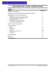
VEHICLE<br />
Engineering Data ................................................................................................................. 1<br />
Top of <strong>Cab</strong>............................................................................................................................ 2<br />
Side View – <strong>Cab</strong> Tilt............................................................................................................. 3<br />
Rear View of Vehicle ............................................................................................................4<br />
Top View of Vehicle .............................................................................................................. 5<br />
ENGINE<br />
Engine Ports......................................................................................................................... 6<br />
Front Engine Accessory Drive.............................................................................................. 7<br />
Engine Location ................................................................................................................... 8<br />
COMPONENTS<br />
Battery Box.......................................................................................................................... 9<br />
Exhaust ................................................................................................................................ 10<br />
Fuel Tank – Between the Rails (BTR) .................................................................................. 11<br />
Fuel Tank – Left Hand Frame-Mounted................................................................................ 12<br />
Fuel Tanks – Dual Frame-Mounted ...................................................................................... 13<br />
Horizontal Fuel Conditioning Module (HFCM)...................................................................... 14<br />
Hydraulic Control Unit ..........................................................................................................15<br />
Parking Brake ....................................................................................................................... 16<br />
INDEX <strong>2006</strong><br />
MODEL YEAR<br />
FRAME<br />
Page Page<br />
Frame Rail Specifications..................................................................................................... 17<br />
Frame – Drilling Restrictions ................................................................................................ 18<br />
Frame Crossmember ........................................................................................................... 19-21<br />
Frame Crossmember Location – Frame Ladder .................................................................. 22<br />
Front Bumper & Tow Hooks ................................................................................................. 23<br />
Front Suspension ................................................................................................................ 24<br />
Rear Spring Suspension – Installed Position ....................................................................... 25<br />
Rear Spring Suspension – Hole Pattern .............................................................................. 26<br />
POWER TAKE-OFF<br />
Power Take Off..................................................................................................................... 27<br />
Required PTO Wiring for Automatic Transmission ............................................................... 28<br />
PTO Wiring for Automatic Transmission............................................................................... 29<br />
APPLICATION INFORMATION<br />
Ground Clearance................................................................................................................ 30<br />
Overhang Limits for Pivoting Bodies and Concentrated AF Loadings ................................. 31
<strong>LCF</strong> CHASSIS SPECIFICATIONS<br />
MODEL <strong>LCF</strong>-45 <strong>LCF</strong>-55<br />
COMPONENTS<br />
GVWR (lbs.) Standard 16,000 19,500<br />
GVWR (lbs.) Optional 15,000 17,950<br />
Max. GCWR (lbs.) 22,500 26,000<br />
Max. Payload (lbs.) 9,720 13,220<br />
WB/AF (in.) 113/47.5, 113/63, 137/47.5, 137/63, 113/47.5, 113/63, 137/47.5, 137/63,<br />
149/47.5, 149/75, 167/75 149/47.5, 149/75, 167/75, 185/96<br />
Front Axle Capacity (lbs.)<br />
Standard 6,000 7,000<br />
Optional None 6000<br />
Front Axle Track (in.) 73.4 73.4<br />
Front Spring Capacity (lbs.)<br />
Standard 6,000 Taper Leaf 7,000 Taper Leaf<br />
` Optional None 6,000 Taper Leaf<br />
Rear Axle Capacity (lbs.) 11,000 13,500<br />
Rear Suspension Capacity (lbs.) 11,000 Single variable-rate 13,500 Single variable-rate<br />
with 1,500 lbs. rubber auxiliary with 1,500 lbs. rubber auxiliary<br />
Stabilizer Bar Front and Rear Front and Rear<br />
Steering Ross TAS37 Ross TAS37<br />
Turning Radius (ft.) 16.5 16.5<br />
Engine 4.5L V6 Power Stroke Diesel 4.5L V6 Power Stroke Diesel<br />
Horsepower/Torque 200 hp/ 440 lb-ft 200 hp/ 440 lb-ft<br />
Air Cleaner Single Element with Filter Minder Indicator Single Element with Filter Minder Indicator<br />
Transmission, Automatic OD 5-Speed TorqShift with Tow/Haul Feature 5-Speed TorqShift with Tow/Haul Feature<br />
Standard Less PTO provision Less PTO provision<br />
Optional With PTO provision With PTO provision<br />
Alternator, Visteon, Pad Mounted 12-volt, 135-amp 12-volt, 135-amp<br />
Battery, Motorcraft, Group 31 Two, 12-volt, 1800 CCA Two, 12-volt, 1800 CCA<br />
Brakes, Hydraulic Four Wheel Disc, Front and Rear Four Wheel Disc, Front and Rear<br />
Split System, 3 Channel ABS Split System, 3 Channel ABS<br />
Frame (psi) 50,000 50,000<br />
RBM (in-lb) 461,000 461,000<br />
Fuel Tank<br />
Standard Single 40 Gal. Between the Frame Rails Single 40 Gal. Between the Frame Rails<br />
Behind the Rear Axle Behind the Rear Axle<br />
Optional Single 35 Gal. LH Frame Mounted Single 35 Gal. LH Frame Mounted<br />
Dual 35 Gal. LH&RH Frame Mounted Dual 35 Gal. LH&RH Frame Mounted<br />
70 Gal. Total Capacity with Duals 70 Gal. Total Capacity with Duals<br />
Wheels<br />
Standard Six, 19.5 x 6.0 hub piloted, ten lug Six, 19.5 x 6.0 hub piloted, ten lug<br />
Steel, Painted White Steel, Painted White<br />
Optional Polished Aluminum (Incl. wheel ornamentation) Polished Aluminum (Incl. wheel ornamentation)<br />
Tires<br />
Standard Goodyear 225/70R19.5 G647RSS Goodyear 225/70R19.5 G647RSS<br />
Optional Michelin 225/70R19.5 XZE Michelin 225/70R19.5 XZE<br />
Body Paint Colors Bright Red (E4), True Blue (L2), Black (UA), Bright Red (E4), True Blue (L2), Black (UA),<br />
Oxford White (YZ), Winter White (W1), Oxford White (YZ), Winter White (W1),<br />
Holly Green (GV), Omaha Orange (NJ), Holly Green (GV), Omaha Orange (NJ),<br />
Bold Yellow (SY), School Bus Yellow (NY) Bold Yellow (SY), School Bus Yellow (NY)<br />
IV
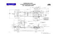
Page 1<br />
<strong>LCF</strong><br />
Wheelbase<br />
(in.)<br />
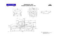
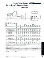
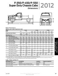
ENGINEERING DATA<br />
Chassis Weight (lbs)** Dimensions (in.) Turning Radius<br />
Front Rear Total<br />
Effective<br />
CA<br />
Useable<br />
CF AF OAL To Curb w/Bumper Clearance<br />
*113 3915 2383 6298 84 131.5 47.5 204.7 16 ft. 7in. 18 ft. 4in.<br />
113 3901 2428 6329 84 147.0 63.0 220.2 16 ft. 7in. 18 ft. 4in.<br />
137 3950 2415 6365 108 155.5 47.5 228.7 19 ft. 3in. 21 ft. 0in.<br />
137 3937 2458 6395 108 171.0 63.0 244.2 19 ft. 3in. 21 ft. 0in.<br />
149 3972 2437 6409 120 167.5 47.5 240.7 20 ft. 8in. 22 ft. 5in.<br />
149 3932 2551 6483 120 195.0 75.0 268.2 20 ft. 8in. 22 ft. 5in.<br />
167 3956 2563 6519 138 213.0 75.0 286.2 22 ft. 5in. 24 ft. 2in.<br />
185 3963 2653 6616 156 252.0 96.0 325.2 24 ft. 6in. 26 ft. 3in.<br />
NOTES: Chart data based on vehicle with standard equipment. Artwork may show some optional equipment.<br />
* Dimension data is based on the 113" wheelbase with 47.5" after frame unless otherwise noted.<br />
** Weight includes standard chassis, standard tires, oil and water, but less fuel.<br />
2 = Frame Height at centerline of front axle with standard tires: unloaded - 28.3"<br />
3 = Frame Height at centerline of rear axle with standard suspension and tires: unloaded - 30.0"<br />
Note: Due to internal spring friction and manufacturing tolerances, these values may vary up to 0.5 inches.<br />
To achieve these normal values directly after loading or unloading a vehicle, it may be necessary to drive the vehicle for a short period.<br />
<strong>2006</strong><br />
MODEL YEAR<br />
NOTE — [ ] DIMENSIONS ARE INCHES.
Page 2<br />
<strong>LCF</strong><br />
TOP OF CAB <strong>2006</strong><br />
MODEL YEAR<br />
NOTE — [ ] DIMENSIONS ARE INCHES.
Page 3<br />
<strong>LCF</strong><br />
SIDE VIEW — CAB TILT <strong>2006</strong><br />
MODEL YEAR<br />
NOTE — [ ] DIMENSIONS ARE INCHES.
Page 4<br />
<strong>LCF</strong><br />
REAR VIEW OF VEHICLE<br />
<strong>2006</strong><br />
MODEL YEAR<br />
NOTE — [ ] DIMENSIONS ARE INCHES.
Page 5<br />
<strong>LCF</strong><br />
TOP VIEW OF VEHICLE<br />
<strong>2006</strong><br />
MODEL YEAR
Page 6<br />
<strong>LCF</strong><br />
ENGINE PORTS <strong>2006</strong><br />
MODEL YEAR
Page 7<br />
<strong>LCF</strong><br />
FRONT ENGINE ACCESSORY DRIVE <strong>2006</strong><br />
MODEL YEAR<br />
4.5L V6 DIESEL
Page 8<br />
<strong>LCF</strong><br />
ENGINE LOCATION<br />
<strong>2006</strong><br />
MODEL YEAR<br />
NOTE — [ ] DIMENSIONS ARE INCHES.
Page 9<br />
<strong>LCF</strong><br />
BATTERY BOX<br />
<strong>2006</strong><br />
MODEL YEAR<br />
NOTE — [ ] DIMENSIONS ARE INCHES.
Page 10<br />
<strong>LCF</strong><br />
EXHAUST <strong>2006</strong><br />
MODEL YEAR<br />
NOTE — [ ] DIMENSIONS ARE INCHES.
Page 11<br />
<strong>LCF</strong><br />
FUEL TANK — BETWEEN THE RAILS (BTR)<br />
<strong>2006</strong><br />
MODEL YEAR
Page 12<br />
<strong>LCF</strong><br />
FUEL TANK — LEFT HAND FRAME-MOUNTED<br />
<strong>2006</strong><br />
MODEL YEAR<br />
NOTE — [ ] DIMENSIONS ARE INCHES.
Page 13<br />
<strong>LCF</strong><br />
FUEL TANKS — DUAL FRAME-MOUNTED<br />
<strong>2006</strong><br />
MODEL YEAR<br />
NOTE — [ ] DIMENSIONS ARE INCHES.
Page 14<br />
<strong>LCF</strong><br />
HORIZONTAL FUEL CONDITIONING MODULE (HFCM)<br />
<strong>2006</strong><br />
MODEL YEAR<br />
NOTE — [ ] DIMENSIONS ARE INCHES.
Page 15<br />
<strong>LCF</strong><br />
HYDRAULIC CONTROL UNIT <strong>2006</strong><br />
MODEL YEAR
Page 16<br />
<strong>LCF</strong><br />
PARKING BRAKE <strong>2006</strong><br />
MODEL YEAR<br />
NOTE — WITH HYDRAULIC BRAKES, THE PARK NOTE<br />
NOTE — BRAKE ASSEMBLIES ARE ATTACHED TO THE<br />
NOTE — REAR AXLE INSIDE (BEHIND) THE ROTOR.<br />
NOTE — THEY ARE MECHANICALLY ACTUATED NOTE<br />
NOTE — THROUGH THE USE OF A FIVE-SECTION<br />
NOTE — CABLE. DUE TO THE CONSTRUCTION OF<br />
NOTE — THE CABLES, IT IS NOT POSSIBLE TO ALTER<br />
NOTE — THE LENGTH.
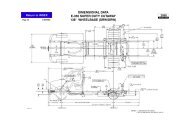
Page 17<br />
<strong>LCF</strong><br />
All Frame Rail<br />
Codes<br />
Side Rail<br />
FRAME RAIL SPECIFICATIONS<br />
DIMENSIONS (inches) YIELD<br />
STRENGTH<br />
NOMINAL<br />
(psi)<br />
NOTE:<br />
# B = High Strength <strong>Low</strong> Alloy Steel<br />
1 = Section Modulus:<br />
Maximum Tolerance: All frame dimensions are at maximum tolerance; used by some competitors as advertised values.<br />
Nominal: Calculated using design dimensions - indicates the design load capacity of the frame.<br />
3 = Rail depth given is for base rail . . . kick-up in AF section is 6.37".<br />
MATERIAL # SECTION MODULUS 1<br />
(inches 3 )<br />
<strong>2006</strong><br />
MODEL YEAR<br />
RESISTING BENDING<br />
MOMENT (in.-lbs.)<br />
Depth Width Thickness Maximun Nominal Maximun Design<br />
Straight Channel Side Rail - Kick-up at Rear Suspension Rearward<br />
9.0 3.0 0.25 50,000 B 10.67 9.23 533,500 461,500
Page 18<br />
<strong>LCF</strong><br />
FRAME — DRILLING RESTRICTIONS<br />
<strong>2006</strong><br />
MODEL YEAR<br />
NOTE — [ ] DIMENSIONS ARE INCHES.
Page 19<br />
<strong>LCF</strong><br />
FRAME CROSSMEMBER <strong>2006</strong><br />
MODEL YEAR<br />
REAR OF ENGINE TRANSMISSION SUPPORT<br />
NOTE — [ ] DIMENSIONS ARE INCHES.
Page 20<br />
<strong>LCF</strong><br />
REAR SUSPENSION/BETWEEN THE RAILS FUEL TANK<br />
FRAME CROSSMEMBER <strong>2006</strong><br />
MODEL YEAR<br />
AFT FRAME<br />
NOTE — [ ] DIMENSIONS ARE INCHES.
Page 21<br />
<strong>LCF</strong><br />
INTERMEDIATE<br />
FRAME CROSSMEMBER<br />
DOUBLE FOR REAR SUSPENSION<br />
<strong>2006</strong><br />
MODEL YEAR<br />
NOTE — [ ] DIMENSIONS ARE INCHES.
Page 22<br />
<strong>LCF</strong><br />
FRAME CROSSMEMBER LOCATION — FRAME LADDER <strong>2006</strong><br />
MODEL YEAR
Page 23<br />
<strong>LCF</strong><br />
FRONT BUMPER & TOW HOOKS<br />
<strong>2006</strong><br />
MODEL YEAR<br />
NOTE — [ ] DIMENSIONS ARE INCHES.
Page 24<br />
<strong>LCF</strong><br />
FRONT SUSPENSION <strong>2006</strong><br />
MODEL YEAR<br />
NOTE — [ ] DIMENSIONS ARE INCHES.
Page 25<br />
<strong>LCF</strong><br />
REAR SPRING SUSPENSION — INSTALLED POSITION<br />
<strong>2006</strong><br />
MODEL YEAR<br />
NOTE — [ ] DIMENSIONS ARE INCHES.
Page 26<br />
<strong>LCF</strong><br />
REAR SPRING SUSPENSION — HOLE PATTERN<br />
<strong>2006</strong><br />
MODEL YEAR<br />
NOTE — [ ] DIMENSIONS ARE INCHES.
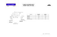
Page 27<br />
<strong>LCF</strong><br />
POWER TAKE OFF<br />
<strong>2006</strong><br />
MODEL YEAR<br />
NOTE — [ ] DIMENSIONS ARE INCHES.
Page 28<br />
<strong>LCF</strong><br />
REQUIRED PTO WIRING FOR AUTOMATIC TRANSMISSION<br />
CAUTION: Installing a transmission-mounted PTO without the required PTO wiring may result in transmission<br />
failure.<br />
To minimize the risk of transmission damage, PTO controls must be integrated into the vehicle wiring.<br />
PTO Request - Applying vehicle battery voltage to the “PTO Request” wire will (1) place the transmission in PTO mode and<br />
(2) elevate idle engine idle speed when certain conditions (described below) are met. This wire MUST be part of the PTO<br />
control system; failing to do so may result in under capacity PTO clutch wear, resulting in rapid contamination of<br />
transmission fluid and internal transmission damage.<br />
Remote PTO Enable - One of the two available remote PTO engine wires MUST also be part of the PTO control system.<br />
The wire must be connected to the PTO Request circuit.<br />
PTO Enable - An output wire is available that indicates when the elevated idle is active. The “PTO Enable” output may be<br />
used at the body builder’s discretion; for example, to restrict PTO operation to stationary only.<br />
PTO Engaged - An input wire is available to control the PTO lamp in the instrument cluster. Applying vehicle battery voltage<br />
to the “PTO Engaged” wire will illuminate the PTO lamp.<br />
“PTO Request”, “PTO Enable”, “PTO Engaged”, and the remote engine PTO signals are blunt cut wires supplied with the<br />
vehicle and are located behind the cab on the left frame rail near the transmission. All other PTO components are to be<br />
supplied by the body builder.<br />
Elevated Idle Operation - When (1) the “PTO Request” input transistions from open circuit to vehicle battery voltage and<br />
(2) the conditions in Table 1 are met, the engine will ramp to 1200 RPM and the “PTO Enable” output will be activated.<br />
While in this mode, normal engine speed hand controls are available; however, the engine will maintain an engine speed<br />
between 1200 and 2400 RPM. The engine will remain in this mode until either (1) the “PTO Request” input is open circuit or<br />
(2) one or more of the conditions in Table 1 are no longer met.<br />
NOTE: A “change-of-state” at the “PTO Request” input is required to re-invoke the elevated idle mode. The operator must<br />
turn off voltage to the “PTO Request” input, and back on again.<br />
Engine Programming - The engine programmable parameter “PTO-CONTROL” must be set to either “1: REMOTE<br />
OPERATION ONLY” or “3: REMOTE AND IN-CAB OPERATION” for PTO installations. This parameter is set to “3:<br />
REMOTE AND IN-CAB OPERATION” from the factory.<br />
<strong>2006</strong><br />
MODEL YEAR
Page 29<br />
<strong>LCF</strong><br />
PTO WIRING FOR AUTOMATIC TRANSMISSION<br />
CF series - PTO Wiring<br />
Circuit Intent Wire Name Description<br />
Input (VPWR) PTO Request Blunt cut wire Circuit No. 2335 Wire Color: Purple/Light Green<br />
Applying vehicle battery voltage to this wire will request the transmission<br />
enter PTO mode and will elevate engine speed if conditions are met.<br />
Output PTO Enable Blunt cut wire. Circuit No.2334 Wire Color: Brown/Yellow<br />
A low-side driver, changing from “open-circuit” to “ground” indicating<br />
elevated idle (PTO) is active.<br />
Intended for turning on a relay coil.<br />
Maximum current is 1 amp.<br />
Input (VPWR) PTO Engaged Blunt cut wire. Circuit No.2336 Wire Color: Red/Orange<br />
Input (VPWR) ECM Remote<br />
Preset PTO<br />
Enable<br />
Input (VPWR) ECM Remote<br />
Variable PTO<br />
Enable<br />
Applying vehicle battery voltage to this wire will activate the PTO lamp in<br />
the instrument cluster, and removing vehicle battery voltage will deactivate<br />
the PTO lamp.<br />
Blunt cut wire. Circuit No.2231 Wire Color: Light Blue/Red<br />
Applying vehicle battery voltage to this wire will enable the Remote Preset<br />
PTO engine operation. This input, or ECM Remote Variable PTO Enable,<br />
is required for PTO.<br />
Blunt cut wire. Circuit No.2232 Wire Color: Red/Light Blue<br />
Applying vehicle battery voltage to this wire will enable the Remote<br />
Variable PTO engine operation. This input, or ECM Remote Preset PTO<br />
Enable, is required for PTO.<br />
Rear Frame Lighting Circuits<br />
Circuit Color Gauge Description<br />
5 Orange-Light Blue<br />
(OR/LB)<br />
9 Light Green-Orange<br />
(LG/OR)<br />
14 Brown<br />
(BR)<br />
511 Light Green<br />
(LG)<br />
18 RH Turn<br />
18 LH Turn<br />
16 Market Lights<br />
16 Stop Lights<br />
<strong>2006</strong><br />
MODEL YEAR
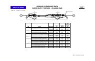
Page 30<br />
<strong>LCF</strong><br />
Wheelbase<br />
(inches)<br />
GROUND CLEARANCE<br />
AF<br />
(inches)<br />
SAE Standard Angles<br />
H106 H147 H107 H107<br />
Bumper<br />
Transmission<br />
Oil Pan<br />
Aft Fuel Tank Frame Rail<br />
113 47.5 20.6º 21.7º 19.9º —<br />
113 63 20.6º 21.7º 19.9º 20.3º<br />
137 47.5 20.6º 19.7º 19.9º 20.3º<br />
137 63 20.6º 19.7º 19.9º 20.3º<br />
149 47.5 20.6º 19º 19.9º 20.3º<br />
149 75 20.6º 19º — 16.9º<br />
167 75 20.6º 18.3º — 16.9º<br />
185 96 20.6º 17.7º — 13.2º<br />
<strong>2006</strong><br />
MODEL YEAR
Page 31<br />
<strong>LCF</strong><br />
Dump, car carriers, and other pivoting bodies impose a great deal of stress on the frame rails around and<br />
aft of the rear suspension area of the frame. In addition, concentrated loads can be applied by the<br />
installation and use of equipment such as lift gates, or the placement of heavy objects on a small section<br />
of the body. The body installer has the responsibility for determining the magnitude of the pivot pin load or<br />
other forces exerted by the body, and for establishing operating guidelines to avoid exceeding the load<br />
limits published in the chart.<br />
The limits shown in this chart are for equal loading on both sidemembers, i.e. the center of gravity of the<br />
raised body is ideally centered and the chassis is on solid, level ground. If the center of gravity is laterally<br />
offset due either to uneven loading, uneven ground, or both, the bending moment on one of the rails<br />
could increase substantially. For this reason the body installer should derate the overhang limits to<br />
account for the lateral shift if either of these factors apply.<br />
These limits apply specifically to concentrated or pivoting loads supported only by the bare chassis, and<br />
do not factor in the load support provided by any part of the installed body structure. Any load exceeding<br />
these limits must be wholly supported by the installed body structure.<br />
Static loading refers to the application of loads without shocks to the chassis or significant dynamic<br />
accelerations applied to the chassis. Dynamic loading refers to all loading conditions during which the<br />
chassis must absorb a shock, stop a load in motion, or support a load during movement of the vehicle.<br />
Examples of dynamic loadings would be dumping materials from a dump body, driving the vehicle over<br />
uneven surfaces with AF loads, or even operating a loaded liftgate.<br />
Because most operations involve dynamic loadings of some kind, the load limits in column “P” should<br />
never be exceeded. The load limits in column “D” should be exceeded only when the excess load is<br />
supported by rail reinforcement or by the body structure.<br />
OVERHANG LIMITS FOR PIVOTING BODIES AND<br />
CONCENTRATED AF LOADINGS<br />
DUMPBODY<br />
PIVOT POINT<br />
L<br />
P (LBS.) D (LBS.) OVERHANG LIMIT, “L” (IN.)<br />
Max. static vertical load (1)<br />
both rails combined<br />
Max. dynamic vertical load (2)<br />
both rails combined<br />
Nominal yield strength - 50,000 PSI<br />
3825 850 96<br />
4950 1100 64<br />
6525 1450 48<br />
9225 2050 32<br />
Maximum (3) 3500 16<br />
Maximum (3) 8900 0<br />
<strong>2006</strong><br />
MODEL YEAR<br />
(1) Maximum static vertical load defined as maximum load which can be applied in steady state condition without exceeding<br />
yield strength of rails.<br />
(2) Maximum dynamic vertical load defined as maximum load which can be applied during equipment operation to provide<br />
adequate margin for shocks and accelerations<br />
(3) Maximum load limited by rear GAWR and vehicle GVWR rather than frame stresses