WKG pipes - Duktus
WKG pipes - Duktus
WKG pipes - Duktus

You also want an ePaper? Increase the reach of your titles
YUMPU automatically turns print PDFs into web optimized ePapers that Google loves.
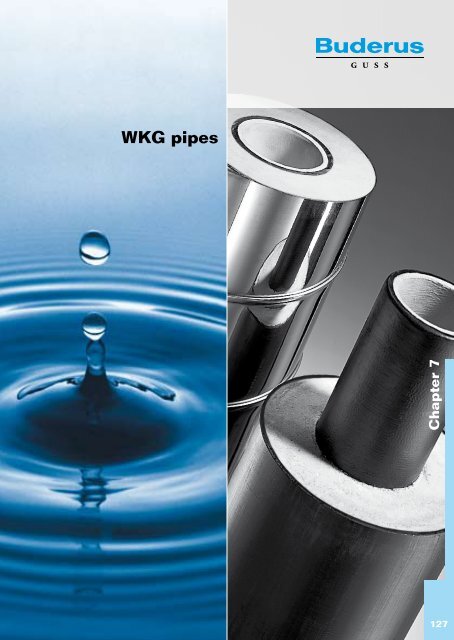
<strong>WKG</strong> <strong>pipes</strong><br />
Chapter 7<br />
127
Information about <strong>WKG</strong> <strong>pipes</strong><br />
Areas of use<br />
Pipelines at risk of frost, e.g.:<br />
� Bridge with pipelines<br />
� Pipelines laid above ground<br />
� Pipelines laid in the ground with minimal depth of covering<br />
� Pipelines at risk of heat loss.<br />
<strong>WKG</strong> pipe system structure<br />
<strong>WKG</strong> pipeline systems consist of <strong>pipes</strong> and socket bends (MMK,<br />
MMQ) made of ductile cast iron acc. to DIN EN 545 (for water) or DIN<br />
EN 598 (for waste water) with TYTON ® push-in socket connections<br />
acc. to DIN 28 603, with optional longitudinal force-locking.<br />
The <strong>pipes</strong> are wrapped in a thermal insulating layer of hard CFC-free<br />
polyurethane (PUR) foam with average overall density of 80 kg/m 3 .<br />
This hard foam is protected from the effects of the weather in one of<br />
two ways: For exposed (FL) pipelines, with a wrap fold sleeve made of<br />
galvanised steel acc. to DIN EN 1506, or optionally stainless steel; and<br />
for pipelines laid in the ground (EL) with minimal covering and thus with<br />
risk of frost, with an outer sleeve made of PE-HD acc. to DIN EN 253.<br />
The gap in the area around the push-in socket connection is filled out<br />
with a ring made of soft polyethylene (WPE) and sealed with a sheet<br />
metal collar (FL system) or a PE shrink strap (EL system).<br />
Chapter 7<br />
129
130<br />
<strong>WKG</strong> <strong>pipes</strong> with TYTON ® -<br />
push-in socket connections<br />
acc. to DIN 28 603 or<br />
restrained BRS ® push-in socket<br />
connections (only up to DN 600)<br />
FL* wrap fold sleeve/EL PE-HD sleeve<br />
DN<br />
length 6m<br />
Dimensions [mm] Weight [kg] ≈ 1)<br />
Ø Da Ø d1 L s D FL <strong>pipes</strong>* EL <strong>pipes</strong><br />
80 180 98 94 41.0 112 108<br />
100 200 118 98 41.0 135 129<br />
125 225 144 101 40.5 168 159<br />
150 250 170 104 40.0 207 195<br />
200 315 222 110 46.5 276 261<br />
250 400 274 115 63.0 369 366<br />
300 450 326 120 62.0 453 456<br />
400 560 429 120 65.5 683 696<br />
500 710 532 130 89.0 966 983<br />
600 800 635 130 82.5 1218 1266<br />
700 900 738 172 81.0 1548 1614<br />
800 1000 842 184 79.0 1896 1974<br />
1) Total weight<br />
Other nominal widths, insulating layers of a different thickness and trace heating on request.<br />
* <strong>WKG</strong>-<strong>pipes</strong> with restrained sockets, type “BRS ® ”: For the intended use in uncovered pipelines,<br />
it is necessary to consult our technical service department for specific advice.
<strong>WKG</strong> <strong>pipes</strong> with restrained BLS ® -<br />
push-in socket connections<br />
FL wrap fold sleeve<br />
EL PE-HD sleeve<br />
DN<br />
������������<br />
length 6m<br />
Dimensions [mm] Weight [kg] ≈ 1)<br />
Ø Da Ø d1 L s D FL <strong>pipes</strong> EL <strong>pipes</strong><br />
80 180 98 207 41.0 121 110<br />
100 225 118 215 53.5 149 140<br />
125 250 144 223 53.0 180 171<br />
150 280 170 230 55.0 212 204<br />
200 355 222 240 66.5 300 288<br />
250 400 274 265 63.0 383 378<br />
300 450 326 270 62.0 476 471<br />
400 560 429 290 65.5 705 715<br />
500 710 532 300 89.0 986 1003<br />
600 800 635 280 82.5 1266 1314<br />
700 900 738 302 81.0 1632 1698<br />
800 1000 842 314 79.0 2004 2082<br />
1) Total weight<br />
Other nominal widths, insulating layers of a different thickness and trace heating on request.<br />
�<br />
� �<br />
�� ��� �<br />
����<br />
Chapter 7<br />
131
132<br />
<strong>WKG</strong> socket bends (MMK) with<br />
TYTON ® push-in socket connections<br />
or<br />
restrained BRS ® push-in socket<br />
connections up to DN 600<br />
FL* wrap fold sleeve/EL PE-HD sleeve<br />
DN Ø Da<br />
MMK<br />
11°<br />
MMK<br />
22°<br />
Lu Dimensions [mm]<br />
MMK<br />
30°<br />
MMK<br />
45°<br />
MMQ<br />
(90°)<br />
80 180 30 40 45 55 100<br />
100 200 35 45 50 65 125<br />
125 225 35 50 55 75 150<br />
150 250 40 55 65 85 175<br />
200 315 45 65 80 110 225<br />
250 400 50 75 95 130 280<br />
300 450 60 90 110 155 330<br />
400 560 70 110 140 200 430<br />
500 710 85 135 170 240 550<br />
600 800 95 155 200 285 645<br />
Other nominal widths, insulating layers of a different thickness and trace heating on request. Other types of<br />
fitting must be insulated on site.<br />
* <strong>WKG</strong>-<strong>pipes</strong> with restrained sockets, type “BRS ® ”: For the intended use in uncovered pipelines,<br />
it is necessary to consult our technical service department for specific advice.
<strong>WKG</strong> socket bends (MMK) with<br />
BLS ® push-in socket connection<br />
FL wrap fold sleeve<br />
EL PE-HD sleeve<br />
DN Ø Da<br />
MMK<br />
11°<br />
MMK<br />
22°<br />
Lu Dimensions [mm]<br />
MMK<br />
30°<br />
MMK<br />
45°<br />
MMQ<br />
(90°)<br />
80 180 30 40 45 55 100<br />
100 225 30 40 50 65 120<br />
125 250 35 50 55 75 145<br />
150 280 35 55 65 85 170<br />
200 355 40 65 80 110 220<br />
250 400 50 75 95 130 270<br />
300 450 55 85 110 150 320<br />
400 560 65 110 140 195 430<br />
500 710 75 130 170 240 –<br />
600 800 85 150 200 285 –<br />
Other nominal widths, insulating layers of a different thickness and trace heating on request. Other types of<br />
fitting must be insulated on site.<br />
Chapter 7<br />
133
134<br />
Example installation of a<br />
bridge pipeline with <strong>WKG</strong> FL system<br />
push-in socket connections<br />
1% incline<br />
<strong>WKG</strong> FL <strong>pipes</strong> and fittings with<br />
restrained BLS ® push-in socket<br />
connections.<br />
One sliding bearing per pipe for support.<br />
Distance to the connection: c. 0.5 metres.<br />
Sliding bearing, e.g. made by Huckenbeck<br />
(supplied by client).<br />
Illustration 1<br />
Manual ventilation<br />
Standard Hawlinger design.<br />
Insulated ventilation can be built<br />
in at a potential high point<br />
(see illustration 1)<br />
Wall duct with<br />
annular gap gasket<br />
Thermally contracting terminal cap<br />
adjoining the crossover to the non<br />
thermally insulated pipeline.<br />
The change in length between the pipeline and bridge can be<br />
compensated by the deflection of the bends.<br />
If you have any questions, please contact our application technicians.
Support for exposed pipelines<br />
Sliding bearings with lift-off guards. For plugging or fixing onto brackets<br />
or fixing onto bridges. Designed for <strong>WKG</strong> <strong>pipes</strong> in line with structural<br />
requirements (e.g. made by Huckenbeck, supplied by the client).<br />
Ring width ‘B’ in mm with a 6 m distance.<br />
DN 80-125 150-200 250-300 400-500 600-700 800<br />
B 100 150 200 300 400 450<br />
Chapter 7<br />
135
136<br />
Down-times for <strong>pipes</strong><br />
with a full charge<br />
(water temperature 8°C)<br />
Exposed pipeline (FL)<br />
Wrap fold sleeve with<br />
TYTON ® push-in socket connection<br />
Medium pipe<br />
DN<br />
Insulation<br />
thickness mm<br />
s D<br />
Outside temperature -20°C Outside temperature -30°C<br />
to 0°C<br />
(h)<br />
to 25% ice<br />
(h)<br />
to 0°C<br />
(h)<br />
to 25% ice<br />
(h)<br />
80 41.0 10 21 7 14<br />
100 41.0 12 28 9 19<br />
125 40.5 16 39 11 26<br />
150 40.0 20 49 14 32<br />
200 46.5 31 80 22 53<br />
250 63.0 51 135 36 90<br />
300 62.0 62 167 44 111<br />
400 65.5 89 241 63 161<br />
500 89.0 150 410 106 273<br />
600 82.5 172 472 120 315<br />
700<br />
800<br />
81.0<br />
79.0<br />
199<br />
224<br />
> 500<br />
140<br />
157<br />
366<br />
415<br />
For other outside temperatures, please contact our application technicians.
Down-times for <strong>pipes</strong><br />
with a full charge<br />
(water temperature 8°C)<br />
Buried <strong>pipes</strong> (EL)<br />
Sleeve made of PE-HD with<br />
TYTON ® push-in socket connection<br />
Medium pipe<br />
DN<br />
Insulation<br />
thickness mm<br />
s D<br />
1.4m max. frost depth<br />
0.3 m covering 0.5 m covering<br />
bis 0°C (h) bis 25% Ice (h) bis 0°C (h) bis 25% Ice (h)<br />
80 41.0 24 68 32 102<br />
100 41.0 31 94 41 142<br />
125 40.5 40 130 53 196<br />
150 40.0 49 169 64 254<br />
200 46.5 76 292 100 440<br />
250 63.0 125<br />
164<br />
300 62.0 151 199<br />
400 65.5 214 282<br />
500 89.0 447<br />
> 500<br />
> 500<br />
600<br />
700<br />
82.5<br />
81.0<br />
> 500<br />
> 500<br />
800 79.0<br />
For other frost depths and top coverings. please contact our application technicians.<br />
Chapter 7<br />
137