Emergency Services - EagleBurgmann
Emergency Services - EagleBurgmann
Emergency Services - EagleBurgmann

Create successful ePaper yourself
Turn your PDF publications into a flip-book with our unique Google optimized e-Paper software.
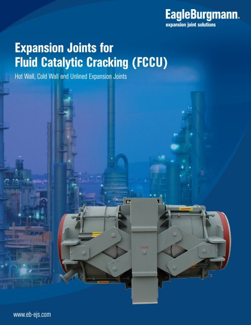
Expansion Joints for<br />
Fluid Catalytic Cracking (FCCU)<br />
Hot Wall, Cold Wall and Unlined Expansion Joints<br />
www.eb-ejs.com<br />
1
2<br />
Advanced Engineering<br />
developed from global experience<br />
With more than 45 years of experience as a solution<br />
provider, <strong>EagleBurgmann</strong> has become a global leader<br />
in developing technology to meet the challenges associated<br />
with controlling thermal expansion of piping and<br />
ducting.<br />
A board range of expertise in applications, equipment<br />
and market sectors contributes to our advanced technologies<br />
that are relevant to the needs of our customers.<br />
Our experience in technology and<br />
product development for many diverse<br />
applications extends benefits that include:<br />
• Value engineering to decrease operational downtime<br />
• Lean manufacturing to reduce costs<br />
• 3D smart design to maximize overall service life<br />
Metal, fabric and rubber expansion joints are our primary<br />
focus – flexible connections, installed in piping<br />
and ducting systems to accommodate expansion, contraction<br />
and in some cases vibration caused by changes<br />
in temperature, pressure and media.<br />
Offering comprehensive service:<br />
• Evaluations & troubleshooting<br />
• Initial dimensional measurements<br />
• Installation & refurbishment<br />
• Supervision & training<br />
• Plant surveys<br />
• <strong>Emergency</strong> services<br />
• Final inspection by experienced service<br />
engineers<br />
Certifications:<br />
• AD 2000-Merkblatt<br />
• ASME, Section VIII, Division 1, U2 unfired pressure<br />
vessel certificate<br />
• Environmental, health & safety certifications ISO<br />
14001:2004 and OHSAS 18001:2007<br />
by Bureau Veritas<br />
• European Pressure Equipment Directive (PED)<br />
97/23/CE<br />
• ISO 3834-2:2006<br />
• ISO 9001:2000 by Bureau Veritas<br />
• ISO 9001:2008 by HSB<br />
• UOP recommended manufacturer<br />
Memberships:<br />
<strong>EagleBurgmann</strong> Expansion Joint Solutions is member<br />
of several associations responsible for establishing<br />
and improving design standards for the expansion joint<br />
industry.<br />
• The European Sealing Association (ESA)<br />
• Euro-Qualiflex is a union<br />
• Expansion Joint Manufacturers<br />
Association (EJMA)<br />
• Fluid Sealing Association (FSA)<br />
Global Manufacturing:<br />
• Europe<br />
• North & South America<br />
• Asia-Pacific<br />
We also have a worldwide sales network supported<br />
by <strong>EagleBurgmann</strong> and Freudenberg offices.<br />
www.eagleburgmann-ej.com
P4. Introduction to Expansion Joints for FCCU<br />
• Critical Application<br />
• The Bellows Membrane<br />
P5. Types of FCCU Expansion Joints<br />
• Hot Wall<br />
• Cold Wall<br />
• Unlined<br />
P7. Design Considerations<br />
• Packed Bellows<br />
• Purged Bellows<br />
• Self-Equalized & Non-Equalized Bellows<br />
P9. Bellows Monitoring<br />
• Multi-ply Bellows<br />
• Normal Two-ply Monitoring<br />
• Redundant Ply<br />
• Active & Passive Monitoring<br />
P5. Exterior Hardware<br />
• Pressure Retaining Covers<br />
• Control Rods<br />
• Sampling Pipes<br />
• Pantographic Linkages<br />
P6. Maintenance & Replacement<br />
• Clamshell Bellows<br />
• KE-CatFlex Cartridge<br />
• Field <strong>Services</strong> & Support<br />
3
4<br />
Introduction to<br />
FCCU Expansion<br />
Joints<br />
• Critical Application<br />
• The Bellows Membrane<br />
Fluid Catalytic Cracking Expansion<br />
Joints<br />
Fluid Catalytic Cracking Units (FCCU)<br />
operate at very high pressures and<br />
temperatures (+1400°F /760°C), consequently<br />
resulting in large thermal<br />
movements that must be absorbed by<br />
the expansion joint. Furthermore, the<br />
introduction of abrasive media (catalyst)<br />
requires additional protection to<br />
avoid gradual deterioration and premature<br />
failure of the expansion joint. The<br />
bellows membrane is the most critical<br />
element of the expansion joint assembly.<br />
Its relatively thin wall construction<br />
is designed for maximum flexibility, but<br />
must be protected against erosive<br />
catalyst and other corrosive media.<br />
Failure of FCCU expansion joints during<br />
operation can be extremely hazardous<br />
to personnel and very expensive to the<br />
refiner.<br />
This technical guide details how Eagle-<br />
Burgmann EJS (EB-EJS) approaches the<br />
design and manufacturing of FCCU<br />
expansion joints, as well as detailing<br />
some of the design elements available<br />
for these units. Since there are no<br />
standard “off the shelf” FCCU joints, all<br />
units are designed specifically for each<br />
application.<br />
Today’s predominant specification for<br />
FCCU joints is the UOP Specification.<br />
This specification provides the basis<br />
for the bellows and related expansion<br />
joint hardware design. In addition to<br />
the UOP specification, EB-EJS has<br />
experience with many other FCC specifications<br />
created by global engineering<br />
companies and refiners such as Shell,<br />
Exxon-Mobil/ KBR, Lummus and more.<br />
Although this technical guide relates<br />
mainly to the UOP specification, we<br />
are experienced with most FCC specifications.<br />
There are various types of expansion<br />
joints used in FCCU applications: Tied<br />
Universals, Hinge, Gimbal and Pressure<br />
Balanced. All of these fall into one of<br />
three major categories: Cold Wall, Hot<br />
Wall, and Unlined FCCU joints that will<br />
be discussed in more detail. The bellows<br />
membrane design for all three categories<br />
is basically the same; although<br />
the bellows membrane can be single<br />
ply, multi-ply, redundant ply or reinforced.<br />
The Bellows Membrane<br />
Today, the material of choice for many<br />
FCCU applications is Inconel 625LCF<br />
(low cycle fatigue). Almost identical to<br />
the original Inconel 625, this special<br />
bellows grade of Inconel 625 is used for<br />
its high strength, excellent fabricability<br />
(including joining), and outstanding<br />
corrosion resistance. Service<br />
temperatures range from cryogenic to<br />
(1800°F/982°C) and this material provides<br />
tighter controls over the carbon,<br />
silicon and nitrogen contents. This produces<br />
a microstructure that enhances<br />
low-cycle fatigue.<br />
Bellows are subject to high bending<br />
stress well into the plastic range to<br />
achieve the movements required by<br />
the thermal expansion of the system.<br />
The finished bellows should be uniform<br />
in shape and pitch with no forming<br />
scratches or heavy tooling marks.<br />
The bellows forming process introduces<br />
work hardening into the bellows<br />
that for the majority of applications is<br />
acceptable. This work hardening increases<br />
the bellow’s ability to withstand<br />
pressure however; it reduces the<br />
cycle life of the bellows. (EJMA cycle<br />
life formula is based on as formed bellows).<br />
If the bellows is annealed after<br />
forming, the reduced pressure capability<br />
needs to be taken into account.<br />
FCCU bellows are often designed to<br />
work at elevated temperatures well<br />
into the creep fatigue range of the<br />
material. To reduce the creep fatigue<br />
effect, some specifications call for the<br />
bellows to be annealed, or solution annealed,<br />
after forming. As most FCCU<br />
bellows are designed to absorb large<br />
movements, beginning with a completely<br />
annealed bellows is usually advantageous.
Types of FCCU<br />
Expansion Joints<br />
• Hot Wall<br />
• Cold Wall<br />
• Unlined<br />
Types of FCCU Expansion Joints<br />
There are three major types of FCCU<br />
expansion joints: hot wall, cold wall,<br />
and unlined.<br />
• Hot Wall<br />
These joints usually have some form<br />
of abrasion resistant lining, comprised<br />
of hexmesh and castable material or<br />
refractory such as Resco AA-22®, a<br />
common abrasion resistant material.<br />
The lining is designed to withstand<br />
the abrasion from the catalyst flowing<br />
through the unit in service. The lining<br />
requires a thermal dry out after<br />
installation.<br />
The lining is not intended to be used<br />
as a thermal barrier; therefore the<br />
shell temperatures of the expansion<br />
joint rise above the allowable temperatures<br />
for normal carbon steels. The<br />
joint shells are normally manufactured<br />
from various Chrome Moly alloys and<br />
stainless steels. Due to their trademark<br />
conical sections near the bellows area,<br />
hot wall expansion joints are easily visible.<br />
The oversize bellows allows for a<br />
smooth flow across the bellows area<br />
using a straight through liner arrangement.<br />
Hexmesh before and after castable material<br />
has been installed.<br />
• Cold Wall<br />
Cold wall joints as their name suggests<br />
are refractory lined to ensure the shell<br />
wall temperatures does not exceed<br />
650°F/343°C.<br />
The lining consists of stainless steel anchors<br />
and a high-density vibrocast refractory<br />
material. Depending on service<br />
condition, the thickness ranges from 4”<br />
to 8” (10 cm to 20 cm). Again, the final<br />
process involves a thermal dry out before<br />
operational service.<br />
The photograph above shows the stainless<br />
steel anchors prior to vibrocasting<br />
the refractory. The internal surface will<br />
be blasted to near white and casting<br />
forms fitted internally to hold the wet<br />
refractory in place until it cures. The finished<br />
unit is shown here. This expansion<br />
joint has been thermally dried and the<br />
lining<br />
process is<br />
now<br />
complete.<br />
After the<br />
unit is<br />
installed<br />
the<br />
remaining<br />
refractory<br />
will be<br />
added onsite.<br />
5
6<br />
• Unlined<br />
Unlined FCCU expansion joints normally<br />
do not carry catalyst in the media,<br />
although the temperatures can be<br />
extremely high. Unlined joints are used<br />
for inlet air, outlet air, and transferring<br />
gases from the reactor, etc. These joints<br />
are still required to accept large movements<br />
and are designed with the same<br />
hardware as lined expansion joints.<br />
Unlined joints are manufactured from<br />
various shell materials dependent upon<br />
the service temperature and media<br />
conditions. Lower temperature and<br />
less severe service applications utilize<br />
the higher-grade carbon steels. In more<br />
severe conditions, stainless steel, and<br />
occasionally, high nickel alloys are used.<br />
The unit shown here is a 66”/167 cm<br />
diameter unlined tied universal incorporating<br />
equalizing hinges for the high<br />
lateral movement. The shell material is<br />
A516-70 fabricated to ASTM specification<br />
672.<br />
36” diameter tied universal elbow expansion joint<br />
for service temperature of 250°F / 121°C<br />
66” diameter unlined tied universal incorporating<br />
equalizing hinges for the high lateral movement.<br />
Hexmesh, S bar and anchors are used to secure the<br />
refractory used on lined expansion joints
Design<br />
Considerations<br />
• Packed & Purged Bellows<br />
• Self Equalized Bellows<br />
• Non-Equalized Bellows<br />
Design Considerations<br />
• Packed and Purged Bellows<br />
When the expansion joint is carrying<br />
catalyst, the fines and dust can collect<br />
under the bellows. The catalyst can<br />
solidify and destroy the bellows membrane<br />
or inhibit the joint movement capability.<br />
The problem exists irrespective<br />
of installation position, however<br />
the more the joint moves towards a<br />
vertical flow up position, the easier it is<br />
for the catalyst to fill the void between<br />
the bellows and liner (bellows annulus).<br />
There have been various methods<br />
used to stop catalyst ingress into the<br />
annulus. The two predominant methods<br />
used today are:<br />
• Packed bellows<br />
• Purged bellows<br />
By far the most common is the packed<br />
bellows.<br />
A packed design incorporates a ceramic<br />
insulation pillow filling the annulus and<br />
a catalyst seal between the liner faces.<br />
The drawing above is a typical liner<br />
seal arrangement. Usually the type and<br />
placement of the seal is indicated on<br />
the individual specification for the expansion<br />
joint.<br />
Packing the annulus of the bellows creates<br />
various design considerations to<br />
be examined carefully. The section of<br />
the drawing above shows that the liner<br />
is connected to the shell wall by a<br />
conical section. The thermal gradient<br />
between the hot liner and cooler shell<br />
would cause severe thermal stress if<br />
the liner were attached with a simple<br />
ring. For this same reason, the downstream<br />
liner is not welded directly to<br />
the shell.<br />
The gap between the shell and liner<br />
end ring allows the end ring to grow<br />
thermally. The growth is absorbed<br />
along the liner seal tube. The opposite<br />
end of the liner seal tube is connected<br />
to the shell with a smaller ring that is<br />
protected from the full media temperature.<br />
It is difficult to see the liner seal after the assembly<br />
of the unit.<br />
Above: Cross section model of an FCCU expansion<br />
joint illustrating the various layers of this complex<br />
unit.<br />
The joint is internally packed with ceramic<br />
insulation to protect the shell<br />
from becoming hot where refractory<br />
cannot be installed due to the liner arrangement.<br />
The surface of the liner has an abrasion<br />
resistant lining. The hexmesh is<br />
transformed into full refractory by suspending<br />
the hexmesh from bars that<br />
are attached to the shell wall. The<br />
seal itself is usually made in two parts,<br />
both stainless steel. The outer cover<br />
is braided hose that is filled with wire<br />
mesh rope. The seal is attached to the<br />
liner with stainless clips that are secured<br />
into the seal itself. Because the<br />
liner gap changes during lateral and<br />
angular movement, the diameter of<br />
the seal has to be calculated in order<br />
to maintain a seal when the liner gap<br />
opens and closes in service.<br />
When a packed design is used, the inner<br />
insulation pillow can reduce the<br />
bellows temperature below the media’s<br />
dew point. If the media contains<br />
chlorides, acids or other elements that<br />
will attack the bellows membrane as<br />
they condense, it is important to maintain<br />
a minimum bellows temperature<br />
during operation. The outer pillow is<br />
used to ensure a minimum bellows<br />
temperature above the media’s dew<br />
point. It is also important to maintain<br />
7
a minimum annulus temperature because<br />
the microscopic particles of the<br />
catalyst that collect in the inner pillow<br />
will cake and solidify if moisture is present<br />
in the bellows annulus. This type of<br />
packing has been very successful and<br />
has proven to be an efficient design in<br />
many applications.<br />
3D cross section model of a purged bellows<br />
8<br />
• Purged bellows<br />
Purged bellows are not as commonly<br />
used today, but they are still installed<br />
successfully on some FCCU units when<br />
required.<br />
The purge is applied to the bellows annulus<br />
in the form of air or steam. The<br />
continuous flow under the bellows<br />
introduces a high-pressure area and a<br />
flow going back into the gas stream.<br />
The purges stop the catalyst from entering<br />
the bellows annulus. Caution<br />
should be taken so that the media used<br />
to purge the bellows is compatible with<br />
the process conditions and does not<br />
cause corrosion problems within the<br />
bellows element.<br />
Typically numerous nozzles are used to<br />
introduce the purge equally around the<br />
annulus. The nozzles are connected to<br />
a circular pipe manifold that surrounds<br />
the bellows on the outside of the joint.<br />
• Self Equalized and Non-Equalized bellows<br />
As previously mentioned, bellows for<br />
FCC units are subject to large movement<br />
deflections in the axial and lateral<br />
planes. Due to these large movements,<br />
the individual convolutions<br />
absorb high deflections. To prevent<br />
the convolutions from contacting each<br />
other, self-equalizing rings are commonly<br />
used. The individual convolution<br />
deflection is determined by the resultant<br />
total deflection for the sum of the<br />
movements divided by the number of<br />
convolutions in the bellows. If a 10<br />
convolution bellows is compressed<br />
2”/5 cm the individual convolution<br />
movement is 0.2”/.51 cm. Theoretically<br />
each convolution will share equally<br />
in the total movement. This is true in<br />
reality if several important conditions<br />
are achieved:<br />
• The convolutions are uniform<br />
• The induced work hardening is<br />
uniform<br />
• The material grain structure is<br />
uniform<br />
When one of the above is not achieved<br />
the result is non-uniform movement<br />
in the individual convolutions. If one<br />
or two of the convolutions in the bellows<br />
are geometrically different to the<br />
rest of the convolutions, this will result<br />
in a non-uniform movement distribution<br />
over the convolutions making up<br />
the bellows. The non-uniform convolutions<br />
will absorb more movement than<br />
others. This may result in the convolutions<br />
touching (bottoming out) and<br />
rubbing in service consequently leading<br />
to premature failure. Increasing the<br />
movement for this bellows to 4”/10<br />
cm will distribute 0.4”/1 cm of movement<br />
to each individual convolution.<br />
This allows for a much smaller error.<br />
Utilizing self-equalizing rings ensures<br />
that non-uniformity does occur even if<br />
the convolutions move slightly<br />
differently. Self-equalizing rings have<br />
no effect on extension movements.<br />
The drawback of using self-equalizing<br />
rings is that the root ring in each convolution<br />
that supports the equalizing<br />
ring reduces the amount of movement<br />
each convolution can absorb as the<br />
bending stress caused by the deflection<br />
is increased.<br />
Equalizing rings will also increase the<br />
cost of the bellows portion of the<br />
expansion joint. Most FCCU applications<br />
do not need self-equalizing rings<br />
should be used only in cases when the<br />
movement conditions cause severe<br />
compression should they be considered.<br />
(Seek the advice of a professional<br />
before specifying equalizing rings.)<br />
Simple equalizing rings<br />
Ring gap closes before convolutions touch<br />
If one con moves before the remaining<br />
convolutions, the equalizing ring stops the<br />
convolution and the movement is forced into<br />
the other convolutions.<br />
<strong>EagleBurgmann</strong> EJS bellows are manufactured<br />
within tolerances that will ensure<br />
the convolutions move uniformly.<br />
Annealing the bellows after forming<br />
will ensure the metallurgical uniformity<br />
of the bellows material. KEB-EJS<br />
would only recommend equalizing<br />
rings in particular situations.
Bellows<br />
Monitoring<br />
• Multi-ply Bellows<br />
• Normal 2-ply Monitoring<br />
• Redundant Ply<br />
• Monitoring Types - Passive &<br />
Active<br />
Bellows Monitoring<br />
The use of multi-ply bellows on FCCU<br />
expansion joints is widespread today.<br />
Various reasons exist for the use of<br />
multi-ply bellows, ranging from redundant<br />
ply design to simple monitoring<br />
for early warning of failure.<br />
• Multi-ply Bellows<br />
Multi-ply bellows in themselves allow<br />
the bellows designer to design for<br />
higher movements combined with high<br />
pressure and still achieve good cycle<br />
life. In laymen’s terms the thicker the<br />
bellows wall thickness the lower the<br />
cycle life for a given movement. By<br />
using two plies of a thinner material<br />
the cycle life will increase for the same<br />
movement without a dramatic drop in<br />
pressure capability. A simple two ply<br />
bellows is designed to use the strength<br />
of both plies to ensure pressure capability.<br />
Redundant ply bellows are designed<br />
so that each ply is strong enough<br />
to withstand the operating conditions<br />
even after one ply fails. These types of<br />
multi-ply designs are usually monitored<br />
to alert the user when one ply fails.<br />
• Normal 2 ply monitoring<br />
Monitoring a normal two-ply design<br />
still offers great advantages for the<br />
operator. A very small leak through<br />
the inner ply will normally not cause a<br />
catastrophic failure. The indicator will<br />
show the leak and the unit can be shut<br />
down for repairs without a total failure<br />
of the unit.<br />
• Redundant Ply<br />
Redundant ply designs offer safety and<br />
outage scheduling benefits. The intent<br />
is to enable the unit to continue to<br />
operate until the next scheduled outage<br />
even after one ply has failed. The<br />
inner ply typically fails before the outer<br />
ply. The operators can see the failure<br />
and plan for changing the unit at the<br />
next scheduled outage.<br />
Monitor Types<br />
Various monitoring devices can be<br />
used from connecting a simple pressure<br />
gauge to electronic sensing devices.<br />
This is a typical monitoring port as it<br />
protrudes through the cover. This unit<br />
was electronically monitored by the<br />
control in the refinery.<br />
Our monitors can provide a visual<br />
indicator that will reveal a ply failure<br />
that connects directly to the port and is<br />
installed before shipment.<br />
• Passive monitor<br />
Passive monitors utilize the line pressure<br />
to indicate an inner ply failure.<br />
When the inner ply fails the line pressure<br />
between the plies will activate the<br />
monitoring device. Passive monitors<br />
will only sense an inner ply failure.<br />
• Active monitor<br />
The active monitor will detect both inner<br />
and outer ply failures. A vacuum<br />
is pulled between the plies before the<br />
monitoring device is installed. If the inner<br />
ply fails, the pressure between the<br />
plies will increase to the line pressure.<br />
If the outer ply fails the vacuum will be<br />
lost.<br />
9
10<br />
Exterior<br />
Hardware<br />
• Pressure Retaining Covers<br />
• Control Rods<br />
• Sampling Pipes<br />
• Pantographic Linkages<br />
• Single Plane Pantographs<br />
• Gimbal Pantographs<br />
• Slotted Hinges<br />
Exterior Hardware<br />
Many different types of hardware are<br />
used to perform various functions on<br />
FCCU joints. This brochure covers the<br />
most widely used hardware.<br />
• Pressure retaining covers<br />
Pressure retaining covers are typically<br />
telescopic and have rings at each end.<br />
The covers are designed to retain the<br />
pressure in case of bellows failure. The<br />
cover can be welded at the end rings<br />
and in the middle to seal the bellows.<br />
Since the bellows will no longer absorb<br />
any thermal movement, care should to<br />
be taken if this is performed.<br />
Pressure retaining covers<br />
• Control Rods<br />
Control rods, as their<br />
name suggests, are used<br />
to control and limit the<br />
movement of the bellows.<br />
By definition, control<br />
rods are not designed<br />
to withstand pressure<br />
thrust.<br />
• Sampling pipes<br />
Pipes which penetrate the shell wall are<br />
used for various reasons and are specified<br />
by the end user. The pipes can<br />
often interfere with other hardware on<br />
the joint. When specifying these pipes,<br />
it is important to be flexible with their<br />
position if possible.<br />
Sampling pipes<br />
Control rods and telescopic covers can be<br />
seen on this FCCU expansion joint in the photograph<br />
above.
• Pantographic linkages<br />
Pantographic linkages are devices that<br />
equalize the amount of axial compression<br />
each bellows absorbs. They ensure<br />
that each bellows takes exactly<br />
half of the axial movement imposed<br />
on the unit.<br />
• Single plane pantographs<br />
Joints that absorb lateral deflection in<br />
only one plane can utilize simple pantographic<br />
linkages.<br />
• Gimbal Pantographs<br />
Joints that need to absorb lateral deflection<br />
in two planes should be fitted<br />
with a gimbal type pantograph. The<br />
center gimbal ring allows the joint to<br />
offset in the opposite plane to the<br />
pantograph without the linkage binding.<br />
This picture shows the pantograph<br />
center pins connected through the<br />
gimbal. The end pins on the gimbal<br />
are hinged to allow lateral movement<br />
in the opposite plane.<br />
FEA Model for<br />
pantogragh<br />
attachment<br />
• Slotted Hinges<br />
The slotted hinges can also be seen in<br />
the photograph above. The main purpose<br />
of the hinges is to fix the center<br />
of rotation for the bellows while at<br />
the same time ensuring each bellows<br />
shares the angulation caused by lateral<br />
deflection equally.<br />
Slotted hinges are also used to take<br />
the dead load of the center spool<br />
off the bellows. This is only effective<br />
when an expansion joint is close to a<br />
horizontal position.<br />
For nearly 30 years, EB-EJS has been<br />
specializing in these expansion joints<br />
as well as other similar complex applications<br />
such as Continuous Catalytic<br />
Regeneration Reforming (CCR Platforming)<br />
, petrochemical/styrene refining,<br />
and turbo expander<br />
piping systems.<br />
Along with CAD and 3D Parametric<br />
Design, EB-EJS also has in-house<br />
finite element analysis and pipe stress<br />
capability. You can reach us 24 hours,<br />
7 days a week for any after hour<br />
emergencies or consultations. Onsite<br />
inspection of your system, including<br />
thermal imagery and bellows condition<br />
analysis are also available upon<br />
request and can be a valuable investment.<br />
EB-EJS specialize in the repair and replacement<br />
of existing FCCU expansion<br />
joints with standard and emergency<br />
deliveries. Contact us at:<br />
+1 (800) 482 2808/+1 (619) 562 6083,<br />
E-mail: sales@keb-ejs.com or your<br />
local representative.<br />
A 3D rendering of a 71”/180cm diameter<br />
regenerated FCCU expansion joint<br />
11
Replacement<br />
Options<br />
• Clamshell Bellows<br />
• KE-CATFLEX ® Cartridge<br />
• Field Service<br />
If you need replacement bellows for<br />
your FCCU expansion joint and completely<br />
removing the unit for a retrofit<br />
is not a viable option, you might consider<br />
installing a clamshell bellows or our<br />
KE-CATFLEX® ® bellows replacement<br />
cartridge for your FCCU. Our clamshell<br />
bellows and bellows cartridges offer a<br />
quicker and more cost-effective solution<br />
to this common dilemma.<br />
With our complete turnkey removal<br />
and replacement service, the clamshell<br />
bellows and the KE-CATFLEX® ® bellows<br />
cartridge are ideal solutions for FCCU<br />
expansion joints that simply need a<br />
bellows replacement. Whether it’s during<br />
a planned turnaround or an emergency<br />
shutdown, <strong>EagleBurgmann</strong> can<br />
provide site supervision or a service<br />
team to support your installation.<br />
KE-CATFLEX<br />
12<br />
® replacement cartridge is an<br />
ideal solution for a quick and cost-effective<br />
repair of your installed FCC expansion joint.<br />
Proper installation of your expansion<br />
joints is key to increasing the service<br />
life and maintaining reliability. Eagle-<br />
Burgmann can help support your next<br />
project. Our field services technicians<br />
have extensive experience having<br />
installed and supervised constructions<br />
all over the world. Helping our customers<br />
reduce costs, decrease down<br />
time and eliminate installation problems,<br />
quickly and safely.<br />
<strong>EagleBurgmann</strong> comprehensive service<br />
includes:<br />
• Evaluations & Troubleshooting<br />
• Initial Dimensional Measurements<br />
• Pipe Stress Analysis<br />
• Installation & Refurbishment<br />
• Supervision & Training<br />
• Onsite Repair – Online and Offline<br />
• <strong>Emergency</strong> <strong>Services</strong><br />
• Final Inspection<br />
• Experience Service Engineers<br />
<strong>EagleBurgmann</strong> Bredan<br />
Metal Expansion Joint Division<br />
Odinsvej 1<br />
DK-6950 Ringkoebing<br />
Tel.: +45 96 74 28 00<br />
Fax: +45 97 32 65 35<br />
E-mail: sales@ke-burgmann.dk<br />
<strong>EagleBurgmann</strong> has extensive experience<br />
having installed and supervised constructions<br />
all over the world.<br />
<strong>Emergency</strong> <strong>Services</strong>:<br />
Fabric expansion joints (US):<br />
Tel. +1 (859) 586 3824 or<br />
+1 (859) 586 3820<br />
Metal expansion joints (US):<br />
Tel. +1 (800) 482 2808<br />
Metal expansion joints<br />
(Outside US):<br />
Tel. +45 96 74 28 00<br />
<strong>EagleBurgmann</strong> EJS<br />
Expansion Joint Solutions<br />
10035 Prospect Ave. Ste. 202<br />
Santee CA USA 92071<br />
Tel.: +(1) 619 562 6083<br />
Fax: +(1) 619 562 0636<br />
E-mail: info@keb-ejs.com<br />
www.eagleburgmann-ej.com<br />
04/01/01.rev02/02.12/US