Estimating errors (digital and analog devices). - JGLG
Estimating errors (digital and analog devices). - JGLG
Estimating errors (digital and analog devices). - JGLG

Create successful ePaper yourself
Turn your PDF publications into a flip-book with our unique Google optimized e-Paper software.
Vers. 1.0 2010/10/14<br />
Experimental Science<br />
P3: Multimeters. Measurement <strong>errors</strong>.<br />
__________________________________________________________________________<br />
1. Purpose<br />
• Measure electric resistance, voltage <strong>and</strong> electric current intensities.<br />
• Estimate <strong>analog</strong>ue <strong>and</strong> <strong>digital</strong> maximum device <strong>errors</strong>.<br />
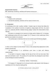
2. Introduction<br />
In what concerns the way they display their result, <strong>devices</strong> can be divided into<br />
<strong>analog</strong>ue <strong>and</strong> <strong>digital</strong>. In an <strong>analog</strong>ue device, the output is a continuous function of the<br />
device’s input (as in a ruler or a mercury thermometer). In the case of a <strong>digital</strong> device the<br />
output takes a numerical form <strong>and</strong> varies discretely (as in a <strong>digital</strong> chronometer or an<br />
electronic scale).<br />
3. Experimental activity<br />
3.1 Material<br />
1 multimeter, 1 voltage supply, several resistances of various nominal values, connecting<br />
wires, crocodiles.<br />
3.2 Procedure<br />
3.2.1 Resistance<br />
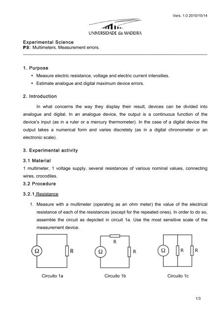
1. Measure with a multimeter (operating as an ohm meter) the value of the electrical<br />
resistance of each of the resistances (except for the repeated ones). In order to do so,<br />
assemble the circuit as depicted in circuit 1a. Use the most sensitive scale of the<br />
measurement device.<br />
Circuito 1a Circuito 1b Circuito 1c<br />
1/3
2. Assess the maximum device error at the used scales.<br />
Vers. 1.0 2010/10/14<br />
3. Compare the measured value with the nominal values (obtained from the provided<br />
colour code table).<br />
4. Repeat the procedure for circuits 1b <strong>and</strong> 1c but using only the repeated resistance<br />
sets.<br />
3.2.2 Voltage <strong>and</strong> current intensity<br />
1. Check if all the voltage supply buttons are at the 0 V <strong>and</strong> 0 A positions.<br />
2. Assemble circuit 2. Use a 1 kΩ resistance.<br />
Circuito 2.<br />
3. Before turning on the voltage supply, ask the teacher to confirm the circuit is properly<br />
assembled.<br />
4. Set the voltage supply to 5 V.<br />
5. Confirm the voltage with a multimeter.<br />
6. In what function setting is the multimeter operating? Are the resistance <strong>and</strong> multimeter<br />
connected in series or in parallel?<br />
7. Calculate the current intensity traversing the resistance.<br />
8. Confirm the obtained value with a multimeter. Do so by turning off the voltage supply<br />
<strong>and</strong> assemble circuit 3.<br />
Circuito 3.<br />
2/3
Vers. 1.0 2010/10/14<br />
9. Before connecting the voltage supply ask the teacher to confirm the circuit is properly<br />
assembled. BEWARE: if the multimeter is still connected in parallel with the voltage<br />
supply when it is turned on its fuse will be burnt.<br />
10. Turn the voltage supply on <strong>and</strong> register your reading.<br />
11. In what function setting is the multimeter operating?<br />
12. Repeat the entire procedure for a different voltage <strong>and</strong> using a different multimeter.<br />
The applied voltage should be such that the current intensity traversing the resistance<br />
should not exceed 25 mA. What it the limit to the voltage you can apply to the<br />
resistance?<br />
13. Compare the measured current intensity with the measured voltage to resistance<br />
ratio.<br />
3/3